


Languages
Pages
Legal


FORM NO. GML-553 REV. 2
Features■ 96% residential gas furnace CSA certified
■ 4 way multi-poise design
■ Two stages of operation to save energy and maintainoptimal comfort level.
■ 7-Segment LED all units
■ Direct Spark Ignition for reliability and longevity
■ Water Management System with patented BlockedDrain Sensor
■ Heat exchanger is removable for improved serviceability.Aluminized steel primary and stainless steel secondaryconstruction provide maximum corrosion resistance andthermal fatigue reliability.
■ Low profile “34 inch” cabinet ideal for space constrainedinstallations.
■ Blower Shelf design – serviceable in all furnace orientations
■ Pre marked hoses – insures proper system drainage
■ Vent with 2" or 3" PVC
■ Replaceable Collector box
■ Hemmed edges on cabinet and doors
■ Quarter turn fasteners for tool less access
■ Integrated control boards feature dip switches for easy system set up
■ Self priming condensate trap
■ Solid bottom included
MAINLINE® ML96TTWO-STAGEMULTI-POSITIONGAS FURNACES
Manufactured for
Mainline®
HVACmainline.com
ML96T96% A.F.U.E.†Input Rates from 40 to 115 kBTU[11.72 to 33.71 kW]
✝A.F.U.E. (Annual Fuel Utilization Efficiency) calculated in accordance withDepartment of Energy test procedures.
Table of ContentsML96T
2 Mainline®
Table of ContentsStandard & Optional Equipment ......................................................................3
Physical Data & Specifications ........................................................................4
Model Number Identification ............................................................................5
Dimensional Data............................................................................................6
Blower Performance Data................................................................................7
Accessories....................................................................................................8
Limited Warranty ............................................................................................9
Standard & Optional EquipmentML96T
Mainline® 3
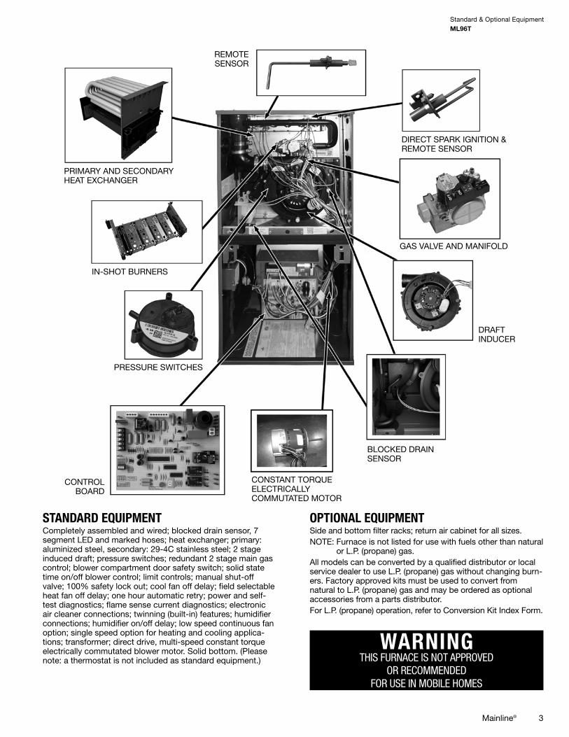
STANDARD EQUIPMENTCompletely assembled and wired; blocked drain sensor, 7segment LED and marked hoses; heat exchanger; primary:aluminized steel, secondary: 29-4C stainless steel; 2 stageinduced draft; pressure switches; redundant 2 stage main gascontrol; blower compartment door safety switch; solid statetime on/off blower control; limit controls; manual shut-offvalve; 100% safety lock out; cool fan off delay; field selectableheat fan off delay; one hour automatic retry; power and self-test diagnostics; flame sense current diagnostics; electronicair cleaner connections; twinning (built-in) features; humidifierconnections; humidifier on/off delay; low speed continuous fanoption; single speed option for heating and cooling applica-tions; transformer; direct drive, multi-speed constant torqueelectrically commutated blower motor. Solid bottom. (Pleasenote: a thermostat is not included as standard equipment.)
OPTIONAL EQUIPMENTSide and bottom filter racks; return air cabinet for all sizes.NOTE: Furnace is not listed for use with fuels other than natural
or L.P. (propane) gas.All models can be converted by a qualified distributor or localservice dealer to use L.P. (propane) gas without changing burn-ers. Factory approved kits must be used to convert from natural to L.P. (propane) gas and may be ordered as optionalaccessories from a parts distributor.For L.P. (propane) operation, refer to Conversion Kit Index Form.
WARNINGTHIS FURNACE IS NOT APPROVED
OR RECOMMENDEDFOR USE IN MOBILE HOMES
PRIMARY AND SECONDARYHEAT EXCHANGER
IN-SHOT BURNERS
PRESSURE SWITCHES
DRAFTINDUCER
CONTROLBOARD
CONSTANT TORQUEELECTRICALLYCOMMUTATED MOTOR
GAS VALVE AND MANIFOLD
DIRECT SPARK IGNITION &REMOTE SENSOR
REMOTESENSOR
BLOCKED DRAINSENSOR

Physical Data & SpecificationsML96T
4 Mainline®
Physical Data and Specifications—Upflow ModelsU.S. and Canadian Models
MODEL NUMBERS ML96TA0402317MSA
ML96TA0602317MSA
ML96TA0702317MSA
ML96TA0852521MSA
ML96TA1002521MSA
ML96TA1152524MSA
HIGH FIRE INPUT BTU/HR [kW] ➀ 42,000 [12.31] 56,000 [16.41] 70,000 [20.50] 84,000 [24.61] 98,000 [28.72] 112,000 [32.82]LOW FIRE INPUT BTU/HR [kW] 29,400 [8.61] 39,200 [11.49] 49,000 [14.36] 58,800 [17.23] 68,600 [20.11] 78,400 [22.97]HEATING CAPACITY BTU/HR [kW] 41,000 [12.02] 55,000 [16.12] 68,000 [19.93] 82,000 [24.03] 95,000 [27.84] 109,000 [31.94]HIGH ALTITUDE OUTPUT 10% DERATE [kW] ➁
36,288 [10.64] 48,384 [14.18] 60,480 [17.72] 72,576 [21.28] 84,672 [24.81] 96,768 [28.36]
BLOWER (D x W)[mm]
11 x 7[279 x 178]
11 x 8[279 x 203]
11 x 8[279 x 203]
11 x 10[279 x 254]
11 x 10[279 x 254]
11 x 11[279 x 279]
MOTOR H.P. [W]–SPEEDSTYPE 1/2 [373]-5-CT 1/2 [373]-5-CT 1/2 [373]-5-CT 1 [746]-5-CT 1 [746]-5-CT 1 [746]-5-CT
MINIMUM CIRCUIT AMPACITY 8 8 8 12 11 11MINIMUM OVERLOADPROTECTION 15 15 15 15 15 15
MAXIMUM OVERLOADPROTECTION 15 15 15 20 15 15
MOTOR FULL LOAD AMPS 6.4 6.4 6.4 10.6 10.6 10.6HEATING SPEED–HIGH FIRE MED MED MED MED-HIGH MED MEDHEATING SPEED–LOW FIRE LOW MED-LOW LOW MED-LOW LOW LOWCOOLING SPEED MED-HIGH MED-HIGH MED-HIGH HIGH HIGH HIGHMINIMUM EXT. STATICPRESSURE (IN. W.C.) [kPa] .18 [.045] .20 [.050] .23 [.057] .28 [.070] .28 [.070] .28 [.070]
MAXIMUM EXT. STATICPRESSURE (IN. W.C.) [kPa] 0.9 [0.22] 0.9 [0.22] 0.9 [0.22] 0.9 [0.22] 0.9 [0.22] 0.9 [0.22]
HEATING CFM @ .2" [.049 kPa]W.C. E.S.P. [L/s] 1117 [527] 1161 [548] 1198 [565] 1715 [809] 1522 [718] 1574 [743]
COOLING CFM @ .7" [.17 kPa]W.C. E.S.P. [L/s] 1102 [520] 1139 [538] 1141 [538] 1745 [814] 1745 [814] 1765 [833]
TEMPERATURE RISE-HIGH FIRERANGE IN DEGREES °F [°C]
20 - 50[11 -28]
30 - 60[17 - 33]
40 - 70[22 - 39]
30 - 60[17 - 33]
40 - 70[22 - 39]
45 - 75[25 - 42]
TEMPERATURE RISE-LOW FIRERANGE IN DEGREES °F [°C]
15 - 45[8 -25]
20 - 50[11 - 28]
30 - 60[17 - 33]
20 - 50[11 - 28]
30 - 60[17 - 33]
35 - 65[19 - 36]
APPROX. SHIPPING WEIGHT(LBS.) [kg] 123.5 [56] 128 [58] 132 [60] 147.5 [67] 152 [69] 165 [75]
AFUE ➂ 96.00% 96.00% 96.00% 96.00% 96.00% 96.00%NOTES: All models are 115V, 60HZ, 1 phase Gas connection size for all models is 1/2" [13 mm] N.P.T. ➀ Installation instructions for high altitude derate. ➁ Canadian installations only. ➂ In accordance with D.O.E. test procedures. *S=Standard ModelsNOTE: Standard model complies with California low nox requirements.
[ ] Designates Metric Conversions

Model Number IdentificationML96T
Mainline® 5
Model Number Identification
ML 96 T A 040 2 3 17 M S A
Mainline
Series96%
Efficient
Motor -ConstantTorque
Design SeriesA = 1st Design
InputBTU/HR
040 = 42,000 [12.31 kW]060 = 56,000 [16.41 kW]070 = 70,000 [20.51 kW]085 = 84,000 [24.62 kW]100 = 98,000 [28.72 kW]115 = 112,000 [32.82 kW]
Stage - Two Airflow3 - Up to 3 Tons5 - Up to 5 Tons
Cabinet Width17 = 17.5"21 = 21.0"24 = 24.5"
Configuration - Multi-Position
S = Standard Revision -Marketing
(A - First TimeRelease)
—
[ ] Designates Metric Conversions

Dimensional DataML96T
6 Mainline®
MODELML96T
LEFTSIDE
MINIMUM CLEARANCE (IN.) [mm]SHIP
WGTS.
FLANGE DIMENSIONSRIGHTSIDE BACK TOP FRONT VENT A B C
040 0 0 0 1 [25] 2 [51] 0 123.5 [56] 171/2 [445] 1617/64 [413] 1613/64 [412]060 0 0 0 1 [25] 2 [51] 0 128 [58] 171/2 [445] 1617/64 [413] 1613/64 [412]070 0 0 0 1 [25] 2 [51] 0 132 [60] 171/2 [445] 1617/64 [413] 1613/64 [412]085 0 0 0 1 [25] 2 [51] 0 147.5 [67] 21 [533] 1949/64 [502] 1945/64 [500]100 0 0 0 1 [25] 2 [51] 0 152 [69] 21 [533] 1949/64 [502] 1945/64 [500]115 0 0 0 1 [25] 2 [51] 0 165 [75] 241/2 [662] 2317/64 [591] 2313/64 [589]
UNIT DIMENSIONS(CLEARANCE TO COMBUSTIBLES)
UNIT DIMENSIONS(CLEARANCE TO COMBUSTIBLES)
*A service clearance of at least 24" is recommended in front of all furnaces [ ] Designates Metric ConversionsSupply and return depicted as upflow configuration.Flange configuration will vary depending on installation orientation.

Blower Performance DataML96T
Mainline® 7
MODELBLOWER
SIZEIN. [mm]
MOTORH.P.[W]
SPEEDTAP
CFM [L/s] AIR DELIVERYEXTERNAL STATIC PRESSURE INCHES WATER COLUMN [kPa]
0.1 [.02] 0.2 [.05] 0.3 [.07] 0.4 [.10] 0.5 [.12] 0.6 [.15] 0.7 [.17] 0.8 [.19] 0.9 [.22]
ML96T402317
11 x 7[279 x 178]
1/2[373]
Low**Med. LoMed.*
Med. HiHigh
8931021115513311423
840976111712911387
788931107512551355
737884103912161320
68383899911761285
61179295711391250
55174591511021215
49167387210651180
43961581910261144
ML96T602317
11 x 8[279 x 203]
1/2[373]
LowMed. Lo**
Med.*Med. Hi
High
9161064119213501397
8691022116113151365
820979112112811333
752937108112491300
685888104112151269
64682099811781236
58677094211391194
53072988510961155
48867384310441109
ML96T702317
11 x 8[279 x 203]
1/2[373]
Low**Med. LoMed.*
Med. HiHigh
9691105123913831482
9161054119813321444
8261010114712991409
798961110112631379
736910106012231343
666840101111821294
61479195111411266
55473588710901226
50768683810341182
ML96T852521
11 x 10[279 x 254]
1[746]
LowMed. Lo**
Med.Med. Hi*
High
12781431160717461955
12301390156517151923
11731343152516791888
11031294148116441853
10451235143315991824
9971177138015501782
9441131132514991745
8971085128414471701
8461039124114051635
ML96T1002521
11 x 10[279 x 254]
1[746]
Low**Med. LoMed.*
Med. HiHigh
12811431156117331956
12321367152216941916
11801316148216541880
11311274143616151845
10811227139415781812
10311181135415351777
9441117130615001745
9031072126514611710
8451019118614111619
ML96T1152524
11 x 11[279 x 279]
1[746]
Low**Med. LoMed.*
Med. HiHigh
13331480162718282030
12731426157417811987
12081373152217281942
11411310147216821898
10741241141716351857
10161190135515781811
9551131130815251765
8981077125014781720
8421024119914201673
** = Factory tap for Low Fire ** = Factory tap for Hi FireNOTE: The Technician/Installer must verify that the furnace is operating within the published rise range before completing the installation
[ ] Designates Metric Conversions.

AccessoriesML96T
8 Mainline®
FILTER RACK FILTER SIZES* INCHES [mm]
MODELRXGF-CB(UPFLOW/
HORIZONTAL)
RXGF-CD(UPFLOW)
RXGF-CC(DOWNFLOW)
ML96TA040 153/4 x 25[400 x 635]
153/4 x 25[400 x 635]
12 x 20[305 x 508]
ML96TA060 153/4 x 25[400 x 635]
153/4 x 25[400 x 635]
12 x 20[305 x 508]
ML96TA070 153/4 x 25[400 x 635]
153/4 x 25[400 x 635]
12 x 20[305 x 508]
ML96TA085 191/4 x 25[489 x 635]
153/4 x 25[400 x 635]
12 x 20[305 x 508]
ML96TA100 191/4 x 25[489 x 635]
153/4 x 25[400 x 635]
12 x 20[305 x 508]
ML96TA115 223/4 x 25[578 x 635]
153/4 x 25[400 x 635]
14 x 20[356 x 508]
FOR HIGH ALTITUDES:NOTE: For Canadian installations only, an optional derate (manifold
gas pressure reduction) method may be used to adjust thefurnace for altitude. See Installation Instructions for moreinformation. This optional method may NOT be used for U.S.installations. See installation instructions as appropriate orificechange is required.
L.P. CONVERSION KIT: RXGJ-FP34
CONDENSATE PUMP KIT: PROSTOCK & 1PCB151TUL
DOWNFLOW/HORIZONTAL CONVERSION KIT: RXGY-CK
DOWNFLOW/HORIZONTAL LEFT ZERO CLEARANCE CONVERSION KIT: RXGY-ZK
COMBUSTIBLE FLOOR BASE: RXGC-B17RXGC-B21RXGC-B24
[ ] Designates Metric Conversions
INDOOR COIL CASINGSMODEL
NUMBER
RXBC-D17A1RXBC-D21A1RXBC-D21B1RXBC-D24A1
VENT TERMINATION KITS: =RXGY-E02: Vertical/Horizontal Concentric Vent Termination Kit 2" Pipe (US Only)
RXGY-E02A: Vertical/Horizontal Concentric Vent Termination Kit 2" Pipe (US & Canadian)
RXGY-E03: Vertical/Horizontal Concentric Vent Termination Kit 3" Pipe (US Only)
RXGY-E03A: Vertical/Horizontal Concentric Vent Termination Kit 3" Pipe (US & Canadian)
RXGY-G02: Direct Vent Furnace Side Wall Vent 2" or 3" (US Only)
RXGY-D05: Combustion Air Drain Kit 2"
RXGY-D06: Combustion Air Drain Kit 3"
NEUTRALIZER KIT: RXGY-A01 (Replacement Cartridge 54-22120-01)FOSSIL FUEL KIT: RXPF-F01, RXPF-F02 (TVA)
EXTERNAL BOTTOM FILTER (UPFLOW/HORIZONTAL) RACK:RXGF-CB
EXTERNAL SIDE (UPFLOW) FILTER RACK: RXGF-CD
EXTERNAL (DOWNFLOW) FILTER RACK: RXGF-CC
*Filter racks are shipped without filters.Filters shipped with furnace may be used or a suitable 1" [25.4 mm] filter.
Limited WarrantyML96T
Mainline® 9
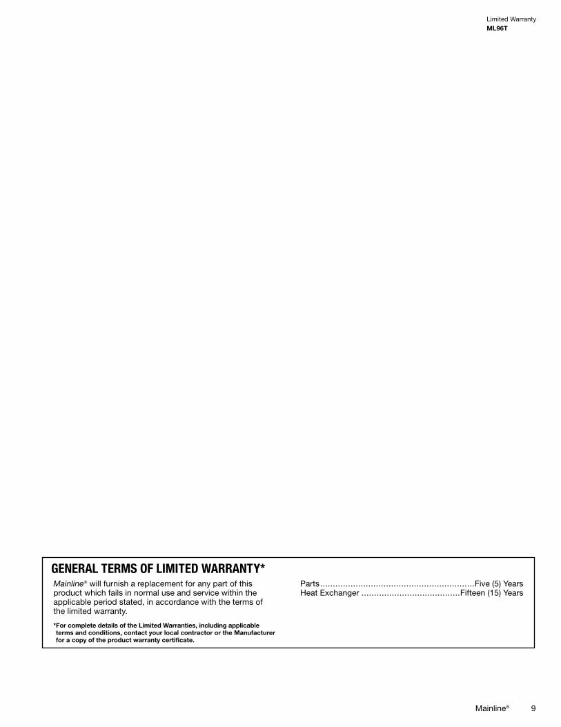
GENERAL TERMS OF LIMITED WARRANTY*Mainline® will furnish a replacement for any part of thisproduct which fails in normal use and service within theapplicable period stated, in accordance with the terms ofthe limited warranty.
*For complete details of the Limited Warranties, including applicableterms and conditions, contact your local contractor or the Manufacturerfor a copy of the product warranty certificate.
Parts.............................................................Five (5) YearsHeat Exchanger .......................................Fifteen (15) Years

NotesML96T
10 Mainline®

NotesML96T
Mainline® 11

Before proceeding with installation, referto installation instructions packagedwith each model, as well as complyingwith all Federal, State, Provincial, andLocal codes, regulations, and practices.
“In keeping with its policy of continuous progress and product improvement, the right is reserved to make changes without notice.”
PRINTED IN U.S.A. 9-17 QG FORM NO. GML-553 REV. 2 Supersedes Form No. ATZ-204
www.MainlineCollection.com
Top Related