


Languages
Pages
Legal


M2: Team Paradigm
:: Final Presentation 2-D Discrete Cosine Transform
Team Paradigm (Group M2):Tommy Taylor Brandon HsiungChangshi XiaoBongkwan Kim
Project Manager: Yaping Zhan
The Future

M2: Team Paradigm
Team Paradigm

M2: Team Paradigm

M2: Team Paradigm
The Future of Technology...

M2: Team Paradigm
Strategic Applications
: High-resolution Digital Television (HDTV)
: MPEG-1 and MPEG-2
: JPEG images

M2: Team Paradigm
:: The Concept
Advertising Profit per Medium
0100000020000003000000400000050000006000000
Ad Source
Do
llar
Fig
ure
Pro
fit
Thinking Outside The Box
We notice an exponential
growth of profit!

M2: Team Paradigm
::What is the Product?: T.A.D.A system (Targeted Advertisement Digital
Ad-board)
: Taxicabs serve as mobile ad unit
: Each cab equipped with a digital ad board
: Ad board contains GPS transmitter, HDTV satellite receiver, solar panel/battery power
Thinking out of the
box
M2: Team Paradigm
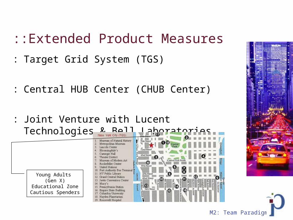
::Extended Product Measures
: Target Grid System (TGS)
: Central HUB Center (CHUB Center)
: Joint Venture with Lucent Technologies & Bell Laboratories
Young Adults (Gen X)
Educational ZoneCautious Spenders

M2: Team Paradigm
::Marketing

M2: Team Paradigm

M2: Team Paradigm
Distribution

M2: Team Paradigm
Risks and Contingencies: Lack of specialization in this area
- Partnership with Lucent Technologies
- Difficulty in entering a new market
:: What are the benefits?
: Expand company’s capabilities
: Gain profit in a new market: Acquire new clients: Advantage over
competitors

M2: Team Paradigm
How does it work?
M2: Team Paradigm
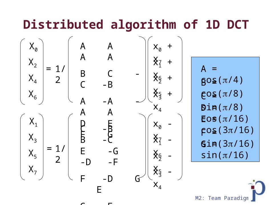
A = cos(/4)
B = cos(/8)
C = sin(/8)D = cos(/16)E = cos(3/16)
F = sin(3/16)G = sin(/16)
A A A A
B C -C -B
A -A -A A
C -B B -C
x0 + x7
x1 + x6
x2 + x5
x3 + x4
X0
X2
X4
X6
= 1/2
D E F G
E -G -D -F
F -D G E
G -F E -D
x0 - x7
x1 - x6
x2 - x5
x3 - x4
X1
X3
X5
X7
= 1/2
Distributed algorithm of 1D DCT

M2: Team Paradigm
In two’s complement representation:
ui = -buiB-1 + j=1, B-1 2-jbui
j
Where, buij is the jth bit, bui
B-1 is the MSB, i.e. the sign bit
Xn = j=1,B-1 2-jDn(bj) – Dn(bB-1), where Dn(bj) = (i=1,3Ci,n buij)
A A A A
B C -C -B
A -A -A A
C -B B -C
b015 b0
14…b00
b115 b1
14…b10
b215 b2
14…b20
b315 b3
14…b30
X0
X2
X4
X6
=
For example, D0(b14) = Ab014+Ab1
14+Ab214+Ab3
14
Distributed algorithm of 1D DCT (cont...)
M2: Team Paradigm
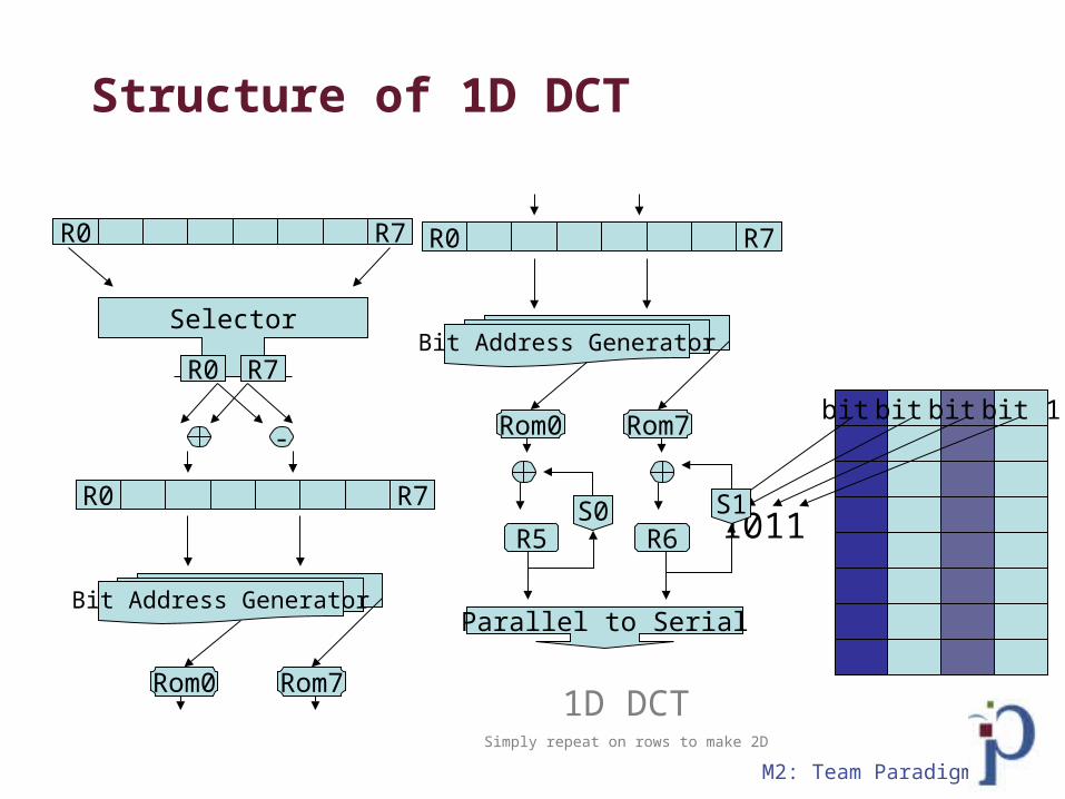
1D DCTSimply repeat on rows to make 2D
-
Selector
R0 R7
R7R0
Bit Address Generator
R0 R7
Rom0 Rom7
bit 1bit 1bit 1bit 1
1011
Structure of 1D DCT
R5 R6S1S0
Parallel to Serial
Bit Address Generator
R0 R7
Rom0 Rom7
M2: Team Paradigm
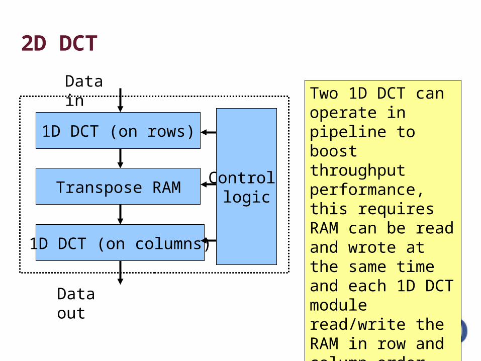
Two 1D DCT can operate in pipeline to boost throughput performance, this requires RAM can be read and wrote at the same time and each 1D DCT module read/write the RAM in row and column order alternatively.
1D DCT (on rows)
1D DCT (on columns)
Transpose RAM
Data in
Data out
Control logic
2D DCT

M2: Team Paradigm
Design Process
M2: Team Paradigm
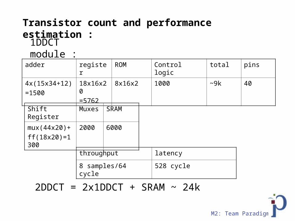
Transistor count and performance estimation :
adder register ROM Control logic total pins
4x(15x34+12)=1500
18x16x20=5762
8x16x2 1000 ~9k 40
1DDCT module :
2DDCT = 2x1DDCT + SRAM ~ 24k
throughput latency
8 samples/64 cycle 528 cycle
Shift Register Muxes SRAM
mux(44x20)+ff(18x20)=1300
2000 6000
M2: Team Paradigm
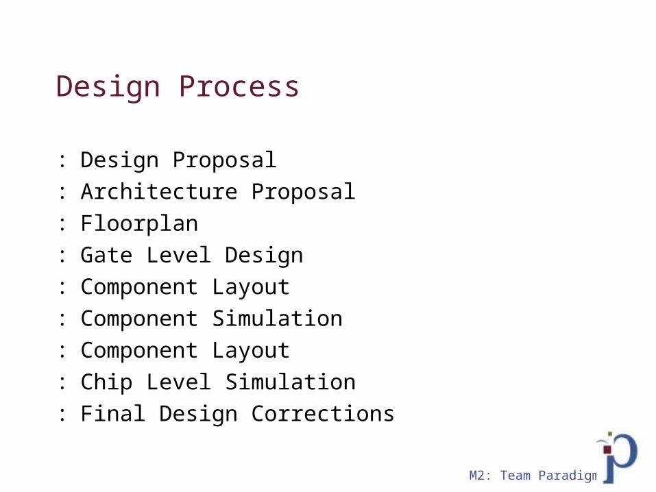
Design Process
: Design Proposal: Architecture Proposal: Floorplan: Gate Level Design: Component Layout: Component Simulation: Component Layout: Chip Level Simulation: Final Design Corrections

M2: Team Paradigm
M2: Team Paradigm
Da Breakdown
: Key to our success was breaking down our components into individual large blocks - 1D DCT- SRAM
: Further we broke down the 1D DCT- easily connected- ease in simulating, lvs'ing,
drc'ing

M2: Team Paradigm
::Mid-Buffer
: Dimensions: - 82.9u X 87.4u
: Metals: - M1, M2, M3
: Directionality:- Left to Right and Down
M2: Team Paradigm
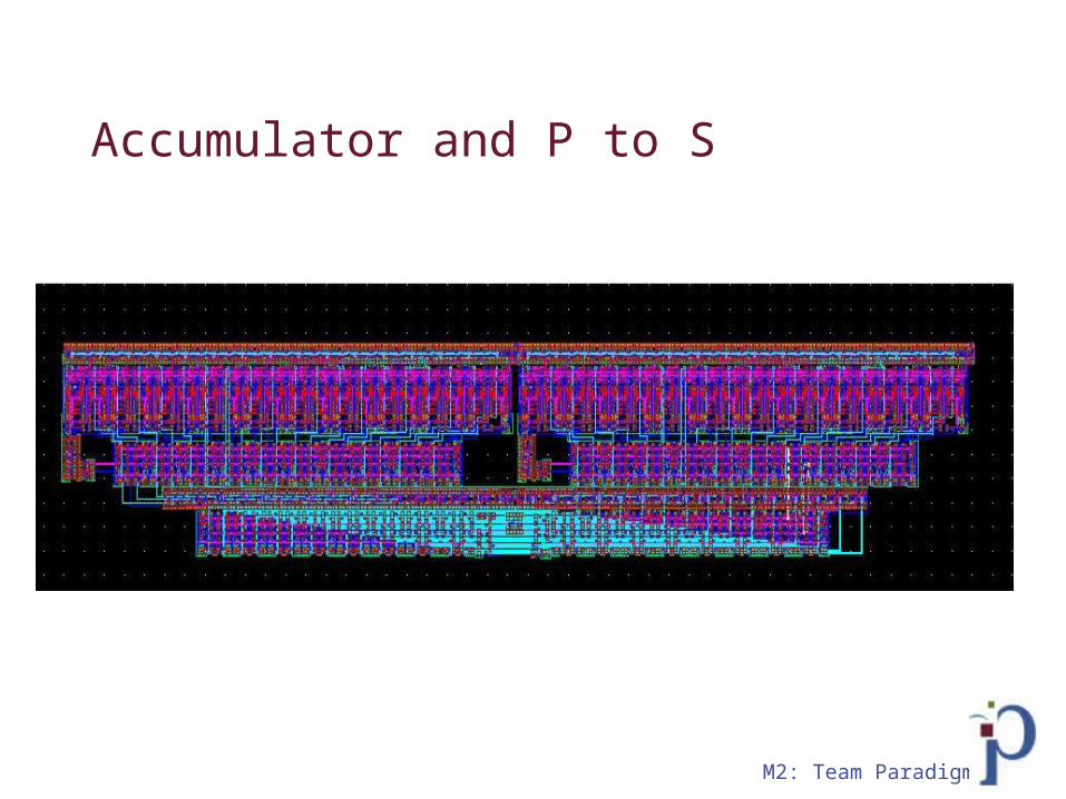
Accumulator and P to S

M2: Team Paradigm
Inbuffer
M2: Team Paradigm
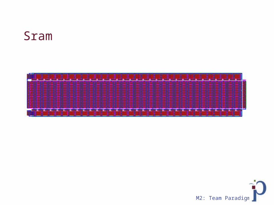
Sram
M2: Team Paradigm
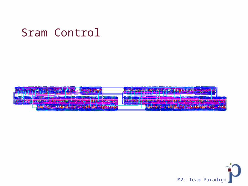
Sram Control

M2: Team Paradigm
Control
M2: Team Paradigm
Floorplan

M2: Team Paradigm
Old floorplan proposal
Sub
Add
Control logic
rom
shift reg
16bi
t 1x8
dem
ux
16bit 4x1 mux
16bit 4x1 mux
reg
reg
reg
reg
reg
reg
reg
reg
16bit 1x4 demux
4bit 16x1 mux A
dd
rom A
dd
4bit 16x1 mux
16bit 1x4 demux
16bit2x1 mux
reg
reg
reg
reg
reg
reg
reg
eg
600u
150u
M2: Team Paradigm
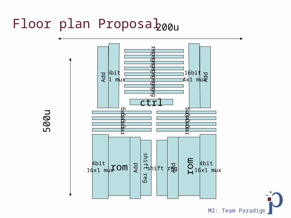
Floor plan Proposal
rom
shift reg
reg
reg
reg
reg
4bit 16x1 mux A
dd
rom
shift regAdd
4bit 16x1 mux
16bit 4x1 mux
reg
reg
reg
reg
Add
regregreg
regregreg
regreg
Add
16bit 4x1 mux
ctrl
500u
200u
M2: Team Paradigm
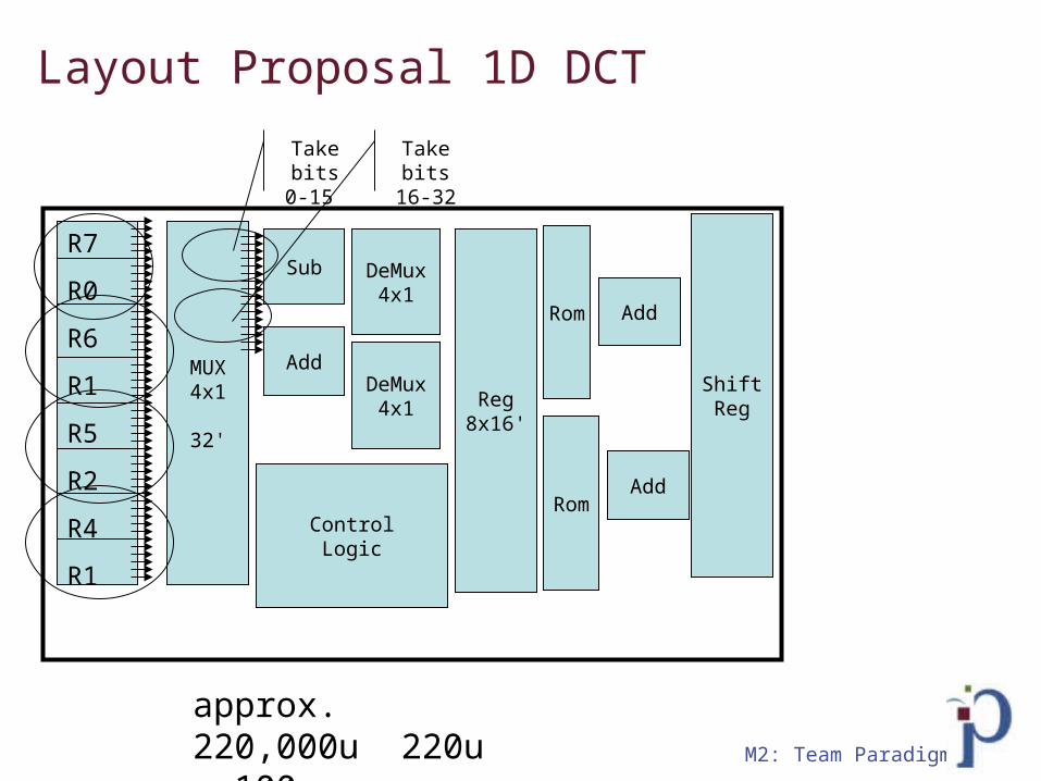
Layout Proposal 1D DCT
MUX4x1
32'
Sub
Add
DeMux4x1
DeMux4x1 Reg
8x16'
R7
R0
R6
R1
R5
R2
R4
R1
Take bits 0-
15
Take bits 16-
32
Add
Add
Rom
Rom
ShiftReg
ControlLogic
approx. 220,000u 220u x 100u

M2: Team Paradigm
2D-DCT – Floorplan (new) 430u by 400u

M2: Team Paradigm
Layout Size Proposal
: Using a reference of an inverter- 7u x 2.5u =14u total area- Contain 2 transistors
: Our design has total of approx 24k- add space for wiring
: Total area estimation of around 400,000u +100,000
: =500,000u

M2: Team Paradigm
Verification
M2: Team Paradigm
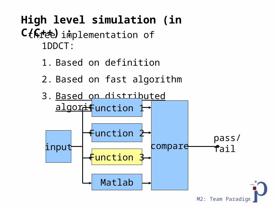
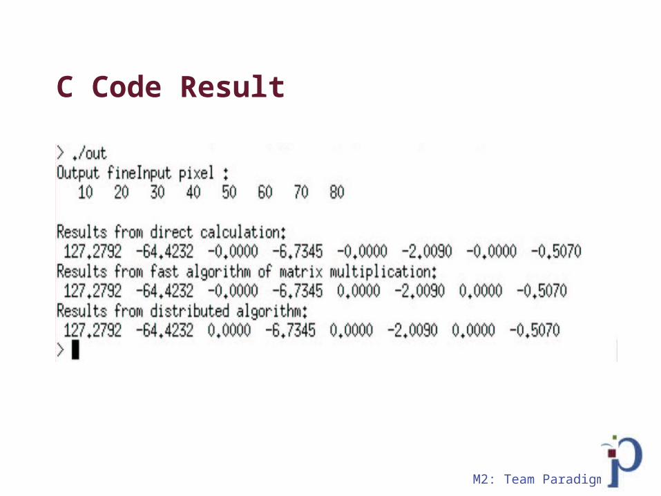
High level simulation (in C/C++) :three implementation of 1DDCT:
1. Based on definition
2. Based on fast algorithm
3. Based on distributed algorithm
input
Function 1
Function 2
Function 3
Matlab
comparepass/fail

M2: Team Paradigm
-
Selector
R0 R7 We begin by inputting eight, sixteen bit values into individual registers
We use a selector to select the registers that will be added and subtracted
The R0 & R7 values are added and subtracted in parallel...So forth for R1 & R6...R2 & R5....R3 & R4
It will take 8 clock cycles to get all the data
R7R0
Step 1:

M2: Team Paradigm
Step 1 (Verilog)
always @ (posedge clk or negedge rst) begin if(rst==0) begin
count <= 0; end else begin
if(in_clr==1) begin count <= 0; end else begin if(in_valid && ~out_full) begin buf[count] <= in_data; count <= count + 1; end end
end end // always @ (posedge clk or negedge rst)
always @ (posedge clk) begin if(in_read) begin
out_data1 <= buf[in_addr]; out_data2 <= buf[7-in_addr];
end end
Write operation
Read operation
M2: Team Paradigm
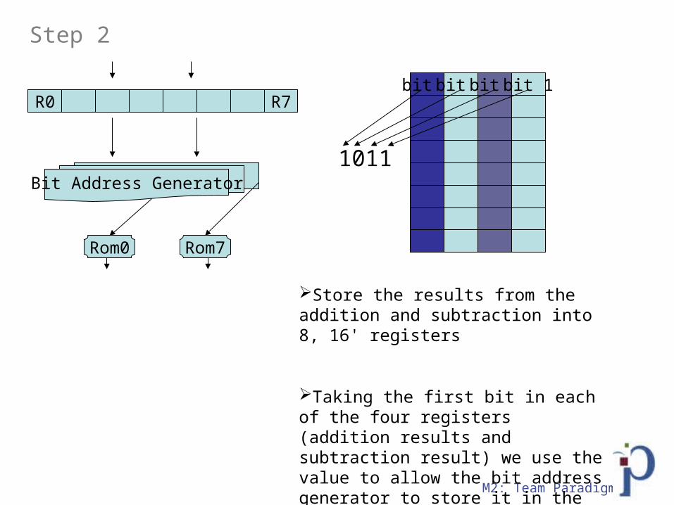
Bit Address Generator
Store the results from the addition and subtraction into 8, 16' registers
Taking the first bit in each of the four registers (addition results and subtraction result) we use the value to allow the bit address generator to store it in the proper position in ROM
R0 R7bit 1bit 1bit 1bit 1
1011
Rom0 Rom7
Step 2

M2: Team Paradigm
Step 2 (Verilog)always @ (posedge clk or negedge rst) begin if(rst==0) begin
count <= 0; end else begin
if(in_clr==1) begin count <= 0; end else begin if(in_read & ~out_full) begin buf[count] <= in_data; count <= count + 1; end end
end end
always @ (in_bitpos) begin out_addr[3] <= buf[0][in_bitpos:in_bitpos]; out_addr[2] <= buf[1][in_bitpos:in_bitpos]; out_addr[1] <= buf[2][in_bitpos:in_bitpos]; out_addr[0] <= buf[3][in_bitpos:in_bitpos]; end
Bit address generator
Read operation

M2: Team Paradigm
Rom0 Rom7
R5 R6
S1S0
Parallel to Serial
From the ROM the data in the addresses are added, stored in a register then the result is shifted (multiplied by a factor of two...two's complement)
Step 3
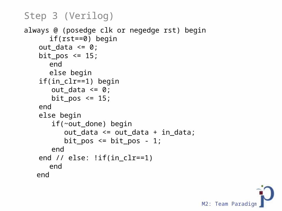
M2: Team Paradigm
Step 3 (Verilog)always @ (posedge clk or negedge rst) begin if(rst==0) begin
out_data <= 0; bit_pos <= 15;
end else begin
if(in_clr==1) begin out_data <= 0; bit_pos <= 15; end else begin if(~out_done) begin out_data <= out_data + in_data; bit_pos <= bit_pos - 1; end end // else: !if(in_clr==1)
end end
M2: Team Paradigm
C Code Result

M2: Team Paradigm
Verilog Verification - 189c, ef9c
M2: Team Paradigm
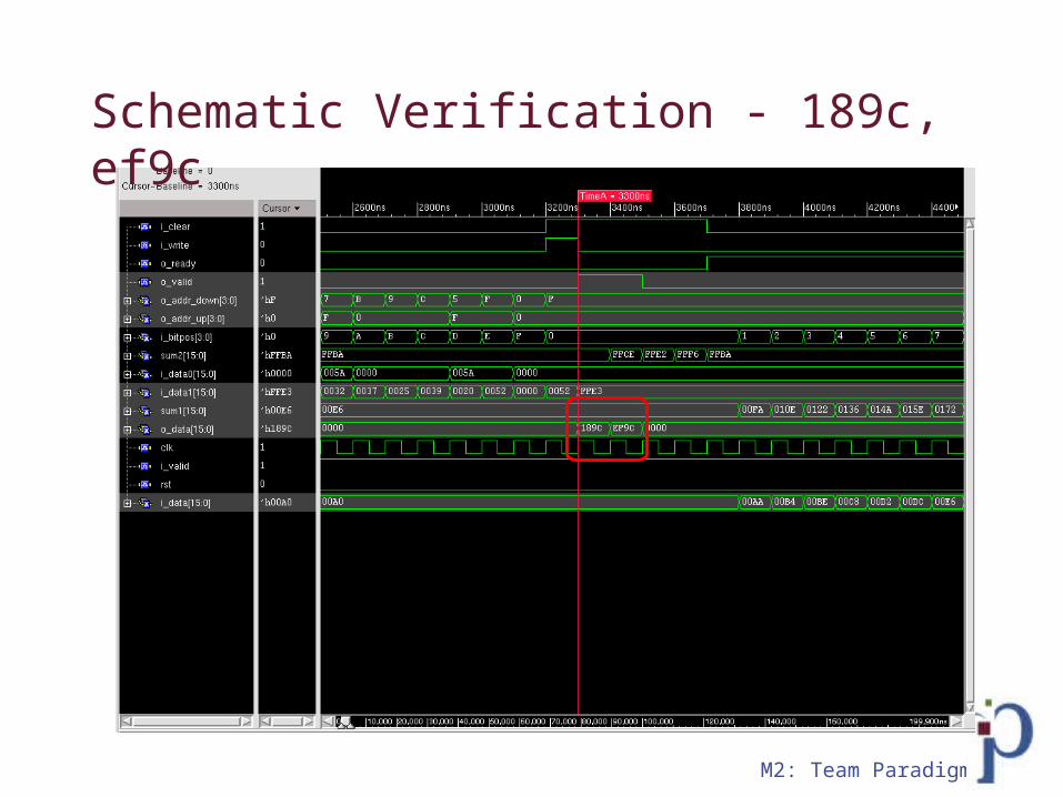
Schematic Verification - 189c, ef9c

M2: Team Paradigm
Layout

M2: Team Paradigm
1D-DCT
Poly and ActiveM1
M2: Team Paradigm
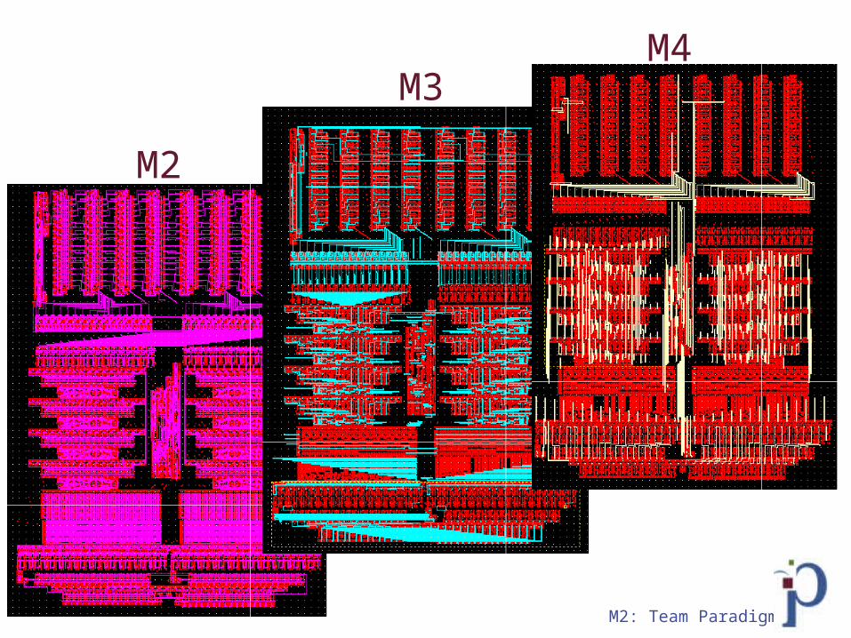
M2
M3M4
M2: Team Paradigm
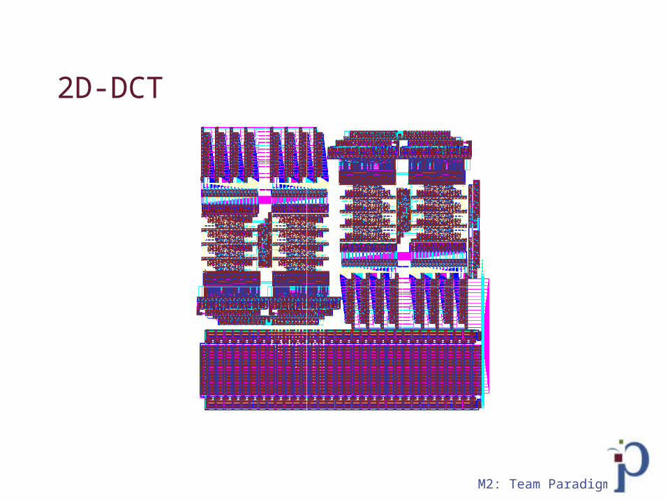
2D-DCT
M2: Team Paradigm
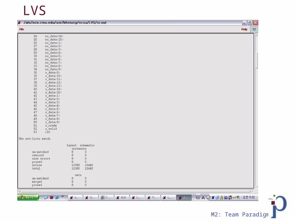
LVS

M2: Team Paradigm
2D DCT dimension
Original:458*450New:458 x 439
M2: Team Paradigm
Simulation strategy
: Simulate 1D DCT : Only simulate using relevant SRAM cells
- Simulating whole chip is inefficient- Simulating whole SRAM is unnecessary- Most thorough yet efficient method
: This plan is consistent with that of the recommendations made by the class faculty
M2: Team Paradigm
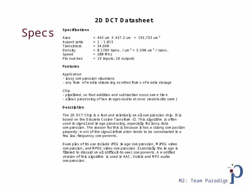
Specs
2D DCT Datasheet Specifications Area = 443 um X 437.3 um = 193,733 um2
Aspect ratio = 1 : 1.013 Transistors = 34,660 Density = 0.1789 trans. / um2 = 5.590 um2 / trans. Speed = 200 MHz Pin number = 19 inputs, 18 outputs Features Application - lossy compression situations - any form of media streaming or other forms of media storage Chip - pipelined, so that addition and subtraction occur same time - allows processing of two images/audio at once (read/write sram) Description The 2D DCT Chip is a fast and relatively small compression chip. It is based on the Discrete Cosine Transform-I I . This algorithm is often used in signal and image processing, especially for lossy data compression. The reason for this is because it has a strong compaction property: most of the signal information tends to be concetrated in a few low-frequency components. Examples of its use include JPEG image compression, MJPEG video compresion, and MPEG video compression. Essentially the image is filtered to discard small (difficult-to-see) components. A modified version of this algorithm is used in AAC, Vorbis and MP3 audio compression.

M2: Team Paradigm
Conclusions

M2: Team Paradigm
Yaping - Integrated Circuit Rapper
: IC Records

M2: Team Paradigm
Changshi - New Age Hippy Group

M2: Team Paradigm
Tommy - Basketball and Beyonce

M2: Team Paradigm
Brandon - The Next Hugh Hefner

M2: Team Paradigm
Bong --> Asain Boy Band - H.O.T.

M2: Team Paradigm
Now that the semester is over....
: We only have one thing to say.....
Yeeeaaaaaaahhhhhhhhh!!!!!!!!
!!!!!!
Top Related