


Languages
Pages
Legal


NASA Tedmical Meummdum 88875
Lubricant Effects on Bearing Life
ErwinV. ZarmkyLewis Research Center
Cleveland, Ohio
for the
OEM Design '86 Conference
New York, New York, December 9-11, 1986
G.3/37
N_7-1E_e7
Unclesq0238
i
A_4 ¸¸ ,
_f
https://ntrs.nasa.gov/search.jsp?R=19870006034 2018-05-29T20:18:43+00:00Z

LUBRICAN1 EFFECIS ON BEARING LIFE
Erwln V. ZaretskyChief Engineer for Structures
National Aeronautics and Space AdministrationLewis Research CenterCleveland, Ohio 44135
"F
I
SUMMARY
Lubricant considerations for rolling-element bearings have within thelast two decades taken on added importance in the design and operation ofmechanical systems. The phenomenon which limits the usable life of bearingsis rolling, element or surface pitting fatigue. 1he elastohydrodynamtc (EHD)film thickness which separates the ball or roller surface from those of theraceways of the bearing directly affects bearing life. Chemical additivesadded to the lubricant can also significantly affect bearings life and reliability. The interaction of these physical and chemical effects is importantto the design engineer and user of these systems. Design _-thods and lubricantselection for rolling.element bearings are presented and discussed.
IN1RODUCI!ON
In rolling, element bearing application, the lubricant can have a markedeffect on bearing life and load capacity, figure 1 illustrates the requiredpoints of |ubricant in a ball bearing, lhese lubrication points are the cage-ball interface, the cage :ace interface and the ball-race contracts.
Most bearing failures occur because of lubricant starvation at thesepoints or improper lubricant selection. 1his problem becomes more acute withhigh-temperature applications.
A lubrlcant has four major functions:
(1) Provide a separating film between rolling and sliding contactingsurfaces, figure 1, thus preventing wear.
(2) Act as a cooldnt to maintain proper bearing temperature.
(3) Prevent the bearing from being contaminated by dirt and othercontaminates.
(4) Prevent corrosion of bearing surfaces.
Oepending on the type of intervening film and its thickness, a number oflubrication regimes can be identified. A classical way of depicting some ofthese regimes is by use of the we11 known Strtbeck curve (fig. 2). Strlbeckperformed comprehensive experiments on Journal bearings around 1900. He meast'-ed the coefficient of friction as a function of load, speed, and temperature.l.a had difficulty, however, condensing this data into usable form. Some yearslater, Hersey performed similar experiments and devised a plotting format basedon a dimensionless parameter, lhe Strlbeck curve, or more appropriately, the
L_

Stribeck-Hersey curve, takes the form of the coefficient of friction as a func-
tion of the viscosity of the ltquld (Z) velocity (N) and load (P) parameterZN/P. ' ' .
At high values of ZN/P which occur at htgh speeds, low loads, and at high
viscosity, the surfaces are completely separated by a thick (>0.25 um)(>10 -5 In.) lubricant film. Thts area ts that of hydrodynamic lubrication
where frlctlon ts determined by the rheology of the lubricant. For noncon-
formal concentratPd contacts where loads are hlgh enough to cause elastic
deformation of tne surfaces and pressure-viscosity effects on the lubricant,another fluid film regime, elastohydrodynamlc lubrication (EHO), can be Identi-
fied. In thls regime film thickness (hi may range form 0.025 to 2 5 um (10-6to 10-4 in.).
As film thickness becomes progressively thinner, surface interactions start
taking place. This regime of increasing friction, which combines asperityinteractions and fluid fllm effects, Is referred to as the mixed lubricationregime.
Finally, at low values of the ZN/P parameter, one enters the realm of
boundary lubrication. This regime Is characterized by the following:
(1) This regime Is highly complex, Involving metallurgy, surface topo-graphy, physical and chemtcal adsorption, corrosion, catalysts and reactionkinetics.
(2) The most Important aspect of this regime Is the formation of protective surface films to minimize wear and surface damage.
(3) The formation of these films Is governed by the chemistry of thefilm-forming agent, as well as the surface of the solid and other environmentalfactors.
(4) 1he effectiveness of these films tn minimizing wear ts determined bytheir physical properties, which include shear strength, thickness, surface
adhesion, film cohesion, melting point or decomposition temperature andsolubility.
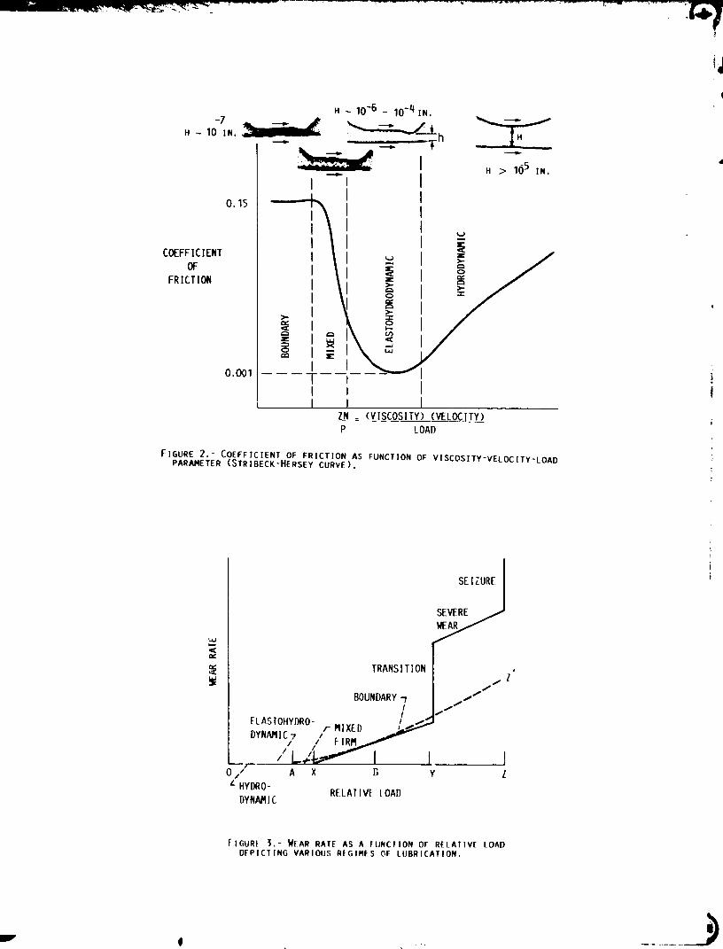
Besides the Strtbeck Hersey curve (flg. 2) already described, an Idealized
plot of wear rate as a function of relative load can also delineate the variouslubrication regimes and some wear transitions (fig. 3).
Region OA of figure 3 encompasses the regimes of hydrodynamic and EHOlubrication, the latter as point A Is approached. Since no surface inter
actions occur In thts region except for startup or shlJtdown, little or no wear
occurs. (1his excludes rolling-element fatigue, which can occur without sur-
face interactions.) Region AX Is the mixed lubrication regime where surface
interactions begin to occur at A and become more prevalent as point X tsapproached. Wear Is low because fluid film effects still exist.
Next there ts region XY In figure 3, which ts the region of boundary
lubrication. The degree of metal to-metal contact and the wear rate increase_s the load increases. Wear Is mtld and tends to be corrosive to the left of
B and adhesive to the right of B. 1he location of B ts quite variable and
depends on the corroslvlty of the lubricant formulation, for a noncorrosive

lubricant, adhesive wear can occur at X. On the other hand, a corrosive addi-tive can extend the boundary regime to Z' before boundary film failure occurs.
Region YZ is the regime of severe wear where severe adhesion and scoring occur.Machinery cannot operate successfully in this region, and, therefore, the loca-tion of this transition point Is quite important. At point Z total surfacefailure occurs, followed by seizure.
In the boundary lubrication regime many properties of t._e liquid lubricantbecome important. These include shear strength, ftlm thickness, melting point,and chemical reactivity with the surface. Operating variables which will affectlubricant film-performance tnclude load, speed, temperature, and atmo phere, asalready discussed. Additives present in the lubricant to serve specific func-tlons will also affect behavior. These additives Include antlwear, antlfoam,antloxtdants, viscosity improvers, and others.
a
b
0
d
E
E'
f
6
Hc
Hmin
hc
hmln
k
N
P
P
p,
O
SYMBOLS
contact ellipse radius transverse to rolling direction, m (in.)
contact ellipse radius In rolling direction, m (in.)
ball or roller diameter, m (in.)
inner ring track diameter, m (in.)
modulus of elasticity parameter, N/m2 (psi)
material elasticity parameter, N/m2 (psi)
conformity
dimensionless EHO materials parameter
dimensionless central EHD film thickness
dimensionless minimum EHD film thickness
central EHO film thickness, m (in.)
minimum EHO fllm thickness, m (in.)
contact ellipse ratio, a/b
speed
dimensionless pressure
bearing pitch diameter, p = d , O, m (in.)
pressure, N/m2 (psi)
normal force, N (|b)
3

RA,RB
Rx
Ry
r
U
UD
UA,UB
kl
x
Y
Z
_p
13
nu
),.
P
o
OA,oB
ro111ng radius, m (in.)
equivalent radius In rolling direction, m (in.)
equivalent radius transverse to rolling direction, m (in.)
radius of body, m (in.)
average surface velocity in x direction, m/see (ln./sec)
dimensionless EHD speed parameter
surface velocity of body In x direction, m/sec
dimensionless EHD load parameter
rolling direction coordinate
transverse dlrecttorl coordinates
viscosity
presseire-visco_lty coefficient, m2/N (psi -1 )
contact angle, deg
absolute viscosity of fluld at ambient prassure N sec/m2(lb sec/ln.2)
ratio of film thickness to composite roughness
Polsson's ratio
inverse curvature sum, m-1 (In.-1)
composite surface roughness, m (in.)
surface roughness of body, m (in.)
angular rotation velocity, rad/sec
Subscripts:
elastlc bodies
cage
inner race
outer race
reference planes
bodies 1 and 2

ELASTOHYDROOYNAMIC$ LUBRICATION
Most ro111ng-element bearings have between their rolllng elements and
raceways an elastohydrodynamlc f11m separating the contacting bodies duringmotlon. This Is Illustrated fnr the rollers of flgure 4, whose surfaces shown
In the enlarged vlew of the contact are not In direct contact but are separated
by a hlghly compressed, extremely thln lubrlcant f11m. Because of the hlghpressures In the contact zone the lubrlcatlon process Is accompanied by some
elastlc deformation of the contact surface shown In figure 5. For thls reason,this process Is referred to as elastohydrodynamlc (EHD) lubrlcant. Grubin was
among the flrst to Identlfy this phenomenon, which also occurs for other oll-
lubrlcated, rol1_ng machlne elements such as gears. Contour plots for a dlmen-
sionless fllm thickness and pressure are shown in figure 6 for a ball on a flatplated
Hamrock and Oowson have derived a simplified approach to calculating theEHD film thickness. They provide dimensionless groupings as follows (refer toflg. 5):
Dimensionless minimum fllm thickness:
hmtnHmln - R (l)
X
which occurs at the tratllng edge of the contact. Dimensionless central filmthickness:
hH =Cc R
x(2)
which Is the average fllm thickness across the entire contact, lhe eQulvalentradius In the rolllng direction Rx is given by
1 1 1- + ---- (3)
Rx rA, x rB,x
and where the equivalent radius transverse to the rolllng direction can befound from
Dimensionless speed parameter:
l l l
- + rB (4)Ry rA,y ,Y
noU
UD =X
(s)

|
L
where the average _urface speed of bodies A and B is
U
uA + uB2 (6)
and where the reduced modulus nf e|astlctty ts
E _ = 2 (7)
01menslonless load parameter:
w = --q--E'R (8)
X
0tmenstonless materials parameter:
G = =pE' (9)
Contact e111pse ratto:
a
k = ; (_0)
where a and _ are the radll of the contact ellipse, _lth radius aoriented perpendicular to the rolllng direction x.
Referring to equations (3) and (4) the equivalent radll for roller andball bearings are given In figure 7. Also, from this flgure, the entrainmentvelocity or average surface speed U at the inner and outer raceway contactcan be derived for equatton (5) where for a bearing inner race
and at the outer rac=
p.2 _ 02)Uo = 4p (mo - wt)
Since for most applications the outer raceway does not rotate andO, then
(i,)
wo equal
U1 = Uo = U (12)
The conventional method of calculating the contact ellipse ratio is toftno a solutton to a transcend3ntal equation that relates the ellipse ratto andthe elllpttc Integrals of the first and second kinds to the geometry of thecontacting soltds. Thts Is usually accomplished by some lterattve numerical
6

_l_lj_w11_." _lF,,._-_'_ -. , _.-. -
procedure. The following stmple expression for k, which eliminates the neces-sity for that procedure, was derived by Brewe and HaFnrock:
(13)
for 0.01 <_ Ry/R x <_ 100,
The approximate solutton of the ellipse ratto as obtatnzd from equatlon (13)_s wtthln 3 percent of the exact solutton for k between 0.056 and 18. For
Ry/Rx greater than unity the major diameter of the contact e111pse w111 beorlented perpendicular to the rolling direction.
The Influence of k and the dimensionless speed Uo, load N, and m_te-rials 6 parameters on the minimum and central ftlm thicknesses was Investi-gated theoretically for the viscous-elastic regtme by Hamrock and Oowson. Th_ellipse ratto was varied from 1 to 8, the dimensionless speed oarameter wasvaried over nearly two orders of magnitude, and the dimensionless load param-eter was varled over one order of magnitude. Conditions corresponding to theuse of solid materials of bronze, steel, and slllcon nltrlde and lubricants ofparafflnlc and naphthentc otls were considered tn obtaining the exponent onthe dimensionless materials parameter. Thirty-four cases were used In obtain-Ing the following dimensionless minimum-film-thickness formula:
0 68 0 49M-0.073 -0.68k)Hmln = 3.63 UO" G " (1 e (14)
For pure cyllndrlcal roller contact (I.e., llne contact) k = ® and the term
In the parentheses In equatlon (14) equals I.
The procedure used to obtaln the central f11m thlckness Is the same as
that used to obtaln the mlnlmum f11m thlckness and results In the followlngformula:
0"67GO'53w-O'O67 (1Hc = 2.6g U0 -0.73k)0.51 e (1S)
lhe measure of the effectlveness of the lubrlcant f11m Is the "lambda" (x)ratlo (I.e., hc/o, central f11m thlckness dlvlded by the composlte surface
roughness of the rolllng-element surfaces). Usually the root-mean-square (rms)surface flnlshes of the contactlng bodles oA and oB are used to determlne
the composlte surface roughness as follows:
I/22 2
o = (o A + oB) (16)
lhe _ ratlo can be used as an Indlcator of rolllng-element performance
and llfe. For k < l, surface smearlng or deformatlon, accompanled by wear,
will occur on the rolllng surface. For 1 < _ < 1.5, surface dlstress may beaccompanled by superflclal surface plttlng. For 1.5 < X < 3, some surface
glazlng can occur wIth eventual roller fallure caused by classlcal subsurface-orlglnated rolllng-element fr_tlgue. Figure 8 shows the effect of X on
rolllng-element fatlgue llfe. At k _ 3, mlnlmal wear can be expected wlth

m
| extremely long ltfe; fatlure will eventually be by classical subsurface-' originated rolling-element fatigue. The most expedient, although not the least; expensive, way of attaining high x ratio ts to select a high-quality surface
finish.
BOUNDARYLUBRICATION
Extreme-pressure and anttwear additives In the lubricating fluid form afllm on the surfaces by a chemical reaction, absorption, or chemtsorptlop.lhese boundary films can be thinner than 0.025 pm (1 pin.) or several micro-inches thick. These films are formed from the chemical reaction of sulfur orfrom the chemlsorptton of tron stearate. Film thickness varies for varioustypes of film. The films can separate the metal surfaces when the EHD film
becomes thin enough for the asperities to interact. The boundary film probablylubricates by mlcroaspertty-elastohydrodynamic lubrication, where the asperi-ties deform under the load. The boundary fllm prevents contact of the aperl-ties and at the same time provides low-shear-strength properties that preventshearing of the metal and reduce the friction coefficient below that of thebase metal. These boundary films provide lubrication at different temperatureconditions depending on the materials used. For example, some boundary filmswtll melt at a lower temperature than others and will then fail to protect thesurfaces. The "failure temperature" ts the temperature at which the lubricantfilm fails. In extreme-pressure lubrication this failure temperature Is thetemperature at which the boundary film melts.
The melttng point or thermal stability of surface ftlms appears to be aunifying physical property governing failure temperature for a wide range ofmaterials. It ts based on the observation that only a solid film can properlyinterfere wlth potential asperity contacts. For this r_ason many extreme-pressure lubricants contain more than one chemtcal for protection over a widetemperature range. For instance, Borsoff found that phosphorous compounds aresuperior to chlorine and sulfur at slow speeds, but sulfur ls superior at highspeeds. He explains this as a result of the increased surface temperature atthe higher speeds. (Most extreme-pressure additives are chemically reactiveand increase their chemical actlvlty as temperature is increased.) Horllckfound that some metals such as zinc and copper have to be removed from lubric-ation systems when uslng certain extreme-pressure additives.
There is strong indication that at k ratios less then 1 1/2, boundaryfilms can affect the resultant fatigue life of ro111ng surfaces. Rolling-element fatigue tests were performed by the author and his colleagues in theNASA five-ball fatigue tester wlth an acid-treated white otl containing either2.5 percent sulfurtzed terpene, 1 percent dtdoderyl phosphlte or 5 percentchlorinated wax. Wlth the exception of the chlorinated wax additive, theseadditives shewed essentially no statistical differences between the lives usingthe base oll with the additive and those without the additive. ]he presence ofthe chlorinated wax produced surface distress and a significant reduction Inllfe.
The additives us_ , the base oil did not change the life ranking of thebearing steels In those .sts where rolling-element fatigue was of subsurfaceorigin. That is, regardless of the additive content of the lubricant, thelives of the three bearing steels tested ranked in descending order as follows:A[S! 52100, A[S[ M-50, AIS! 1018. Recent published work by the authors and hts

.................... ° ................... _-Z _._LL_.'_.L.. _-
collegues showed that with spur gears, where X Is approximately 1, thepresence of a phosphorous-type load carrying additive In the lubricant produceda significant improvement tn life over lubricants without this type of addi-tive. The presence of a sulphus type anttwear additive also showed an improve-ment In life. However, this improvement was not considered statisticallysignificant.
The presence of the antlwear and extreme-pressure additive to lubricantrolling-element bearings ts extremely important especially under heavilyloaded, high-speed, high-temperature conditions. These additives protect thecontacting surface from wear and surface distress even under favorable EHOlubrication conditions In raceway contacts. In many cases, boundary lubrica-tion Is dominant between the cage and ball (roller) contact and the cage-racecontact (see fig. 1). Without the additive forming a boundary film, grosswear can occur.
LUBRICANT SELECTION
lhe useful bulk temperature limits of several classes of fluld lubricantsIn an oxidative envlronmenf are given tn table [. Grease lubricants are listedIn Table II. The heat transfer requirements of bearings dictate whether agrease lubricant can be used. Grease lubrication permits the use of simplifiedhousing and seals.
lhe most commonly used lubricant Is mineral oil, both tn liquid and greaseform table III. As a liquid, mineral oll usually contains an antlwear orextreme-pressure (EP) additive, an antlfoam agent, and an oxidation inhibitor.In grease the antlfoam agent Is not required.
Synthetic lubricants have been developed to overcome some of the harmfuleffects of lubricant oxidation. However, synthetic lubricants should not beselected over readlly available and invariably less-expensive mineral oils Ifoperating conditions do not require them. It Is usually easier to incorporatesynthetic lubricants In a new design than to convert an existing machine tothetr use.
1he selection of a lubricant Is not always lndeoendent of the appltcdtlon.Hence, very ltttle can be done once the machine Is In the fteld. However.where choice can be made, the designer or the perscn selecting th_ lubricantshould consider the anticipated operating temperature of the bearings. Ix mGs_cases, the lubricants heat transfer and rheloglcal propert!es wlll affect tPtstemperature. However, a first order estimate can be made and the selection canbe made on the lubricants limiting temperature. Once, the chemical type hasbeen selected, lubricant viscosity should be a consideration. T_hle III givescomparative viscosities for various numerical oll classlflc3tlon_. Knowing theviscosity at the bearing temperature and the pressure viscosity coefficient ofthe selected lubricant (_able IV gtve representative values of pressure-viscosity coefficient _p) the EHD ftlm thickness can be calculated togetherwith the film parameter X and realtlve bearing life. Where there are too lowvalues of X or life, consideration may be given to either lowerln_ bearingtemperature, increasing bulk lubricant viscosity and/or changing lubricant type.
I

L
LUBRICANT AOOIT[VE SELECTION
Unl!ke the lubricant, It Is almost Impossible to independently select alubricant additive package from a given lubricant brand. Whtle the lubricantchemtcal type Is known, generally the addltl4es contained therein are proprie-tary to the manufacturer. Unless, there Is economic incentive for the manu-facturer to blend an additive package for a given use, the machine designer Islocked Into what ts currently In the market place. Probably no two lubricantn_lnufacturers supply the same additive package even though supplying the samebase stock. Hence, the major difference between brands x and y wlll bethe additives contained therein.
Some of the extreme-pressure additives commonly used contain one or morecompounds of chlorine, phosphorus, or sulfur or lead soaps. Many chlorine-containing compounds have been suggested as extreme-pressure additives, butfew have actually been used. Some lubricants are made with chlorine-containingmolecules where the C13°C linkage Is used. For example, either trl (trt-chioroethyl) or trt (trlchlortert butyl) phosphate additives have shown highload-carrying capacity. Other chlorine-containing additives are chlr.rlnatedparaffin or petroleum waxes and hexachlorethene.
The phosphorus-contatnlng compounds are perhaps the most commonly usedadditives for oils. Some aircraft lubricants have 3 to 5 percent trtcresylphosphate or trtbutyl phosphlte as either an extreme-pressure or anttwear agent.Other phosphorous-containing extreme-pressure agents used tn percentages of 0.1to 2.0 could be dodecyl dlhydrogen phosphate, delthyl-dlbutyl-, or dtcresyl-phenyl trtchioroethyl phosphtte and a phosphate ester containing a pentachloropphenyl radical. Host of the phosphorous compounds tn olls also have otheractive elements.
The sulfur-contalnlpg extreme-pressure additives are belleved to formIron sulfide films that prevent wear at high loads and speeds. However, theygive higher friction coefficients and are therefore usually supplemented byo_iler boundary-film-forming Ingredients that reduce friction. The sulfur com-pounds should have controlled chemical activity (e.g., otls cont(_lntng dlbenzyldisulfide of 0.1 or m_re percent). Other sulfur-containing extreme-pressureadditives are dtamyl d_ulflde, dllauryl disulfide, suifurlzed oletc actd andsperm oll mixtures, and dtbutylxanthtc acid disulfide.
Lead soaps have been used In lubricants for many years. They resist theslldtng action In bearings and help prevent corrosion of steel In the preseLiceof water. Some of the leaG soaps used tn lubricants ace lead oleate, leadftshate, lead-12-hydroxystf:arate, and lead naphthenate. Lead naphthepate tsused most often used because of Its solubility. Lead soaps are used In concen-trations of 5 to 30 percent.
Other additive compounds contain combinations of these elements. Hostextreme-pressure lubricants contain more than one extreme-pressure a_dltlvaNeedless to say, the selection of a proper extreme-pressure additive ts a com-pllcated process. The word "susceptibility" Is frequently used with referenceto addltlve_ tn o11s to lndlcaLe the ability of the otl to accept the additivewtLhout deleterious effects. Such properties as solubility, volatility, sta-bility, compatibility, load-carrying capacity, and cost must be considered.Many oll compounds depend on the use of proprietary, or package, _xtreme-pressure aOdltlves. AS a result, the lubricant manufacturer does not evaluate
10

the additives' effectiveness. Becauseof this, any selection of extreme-pressure additives should be supported by an evaluation program to determinetheir effectiveness for a given application.
CONCLUSION
lhe selection of a lubricant for a rolling-element bearing application isas important as the actual bearing design. In fact, good engineering practicedictates that both the design of the bearing and lubricant selection be inte-grated. Lubricant type should be selected based upon lubricant temperaturelimitations. Mtneral oll type lubricants should be selected over the syntheticlubricants where temperatures permit. Elastohydrodynamlc (EHD) lubricationfilm thickness should be calculated. Effects of the EHD film on bearing llfeshould be determined. Additive selection while not always specifiable, shouldbe considered and test programs initiated where boundary lubrication is antic-ipated. Good rolling-element bearing lubrication practice is not "off-the-shelf" oll can application.
,
2,
,
.
,
,
,
B°
,
10.
REFERENCES
Anderson, W.J.: Elastohydrodynam!c Lubrication Theory as a Design Param-eter for Rolling-Element Bearings. ASME Paper 70-DE-19, May 1970.
Anderson, W.J.; and Zaretsky, E.V.: Rolling-Element Bearings. Mach.Des., vol. 42, no. 15, June 18, 1970, pp. 21-37.
Bamberger, E.N., et. al.: Life AdJubtment Factors for Ball and RollerBearings - An Engineering Design Guide. ASNE, 1971.
Beerbower, A.: Boundary Lubrication. GRU.1GBEN.72, Esso Research andEngineering Co., June 1972.
Borsoff, V.A.: Funaamentals of Gear Lubrication. Annual Rep., ShellDevelopment Co., June 1955.
Borsoff, V.A.; and Lulwack, R.: F:mdamentals of Gear Lubrication. ShellDevelopment Co., June 1951.
Bowden, F.P.; and Tabor, O.: lhe Friction and Lubrication c,f Sollds,Vol. 2, Clarendon Press, Oxford, 1964, p. 365.
Brewe, D.; and Hamrock, B.J.: Simplified Solution for Stresses and
Deformations. J. Lubr. Techno1., vol. lOS, no. 2, Apr. 1983, FP. 171-17l.
Buckley, D.H.: Trlbology. Advanced Materlals Technology, NASA CP-225),C.P. 6}ankenshlp and L.A. Telchman, eds., 1982, pp. 391-409.
Coy, J.J.; Townsend, D.P.; and Zaretsky, E.V.: Gearing. M_chanlcal
Design and Systems Handbook, H.A. Rothbart, ed. McGraw-Hlll NY 1986,PP. 38.59-38.66. ' ' '
11

11.
12.
13.
14.
15.
lb.
17.
lB.
19.
20.
21.
22.
23.
Felr, R.S.: Chemistry In Concentrated-Conjunction Lubrication. Inter-disclp;_nary Approach to the Lubrication of Concentrated Contacts, NASASP-237, P.M. Ku, ed., 1970, pp. 489-527.
Godfrey, O.: Boundary Lubrication. Interdisciplinary Approach to Fric-tion and Near, NASA SP-181, P.M. Ku, ed., ]968, pp. 335-384.
Grubtn, A.N.: Fundamentals of the Hydrodynamic Theory of Lubrication ofHeavily Loaded Cylindrical Surfaces. Investigation of the Contact ofMachine Components, Kh.F. Ketova, Ed., Translation of Russian Book No. 30,Central Scientlf%c Institute for Technology and Mechanical Engineering,_oscow, 1949, Chapter 2. (Available from Department of Scientific andIndustrial Research, Great Britain, Transl. CTS-235 and Special Libraries
Association, Transl. R-3554.)
Hamrock, 6.3.; and Anderson, N.J.: Rolling-Element Bearings. MechanicalDestgn and Systems Handbook, H.A. Rothbart, ed., McGraw H111, NY,
pp. 29-5!-29.55.
Hamrock, B.J.; and Oowson, O.: Isothermal Elastohydrodynam%c Lubricationof Point Contacts-Part III-Fully Flooded Results. J. Lubr. Technol.,vol. 99, no. 2, Apr. 1977, pp. 264-276.
Hersey, M.D.: The 'aws of Lubrication of Horizontal Journal Bearings.J. Wash. Acad. Sc%., vol. 4, 1914, pp. 542-552.
Horlick, E.J.; and Thomas, O.E.: Recent Experiences tn the Lubricationof Naval Gearing. Gear Lubrlcat%on Symposium, Institute of Petroleum,
1966.
Jones, W.R. Jr., et al.: Pressure-Viscosity Measurements for SeveralLubricants to 5.5x10⁸ Newtons per Square Meter (8x10⁴ psi) ana 149 °C
(300 °F). ASLE lrans., vol. 1B, no. 4, 1975, pp. 249-262.
Lowenthal, S.H.; and Zaretsky, E.V.: lractton Drives. Mechanical nes_grland Systems Handbook, H.A. Rothbart, ed., McGraw Hill, NY, 1986,
pp. 34.7-34.9.
Present, D.L., et al.: Advanced Chem_,.al Characterization and PhysicalProperties of Eleven Lubricants. (AFLRL-166, Army Fuels and I_ubr%cantsResearch I_ab) NASA CR-1681BT, 1983.
Stribeck, R.: Characteristics of Plain and Roller Bearings. VOI Z.,vol. 46, 1902.
lownsend, D.P.; Zaretskyo E.V.; and Sc%bbe, H.W.: Lubricant and AdditiveEffects on Spur Gear Fatigue Life. J. lr%bo%oqy, voi. 108, no. 3, July
1986, pp. 468-477.
Zaretsky, E.V.; and Anderson, N.J.: How to Use What We Know About EHOLubrication. Mach. Oes., vol. 40, no. 26, Nov. ?, 1968, pp. 167-173.
12

T_RLF I. - L!IRRICANT
TVDp
i
E _ineral nil
I qi_stpr
Tvp_ If pstpr
T r i_<,tpr
Suporr_fined and c, vnth_t ir
mi n,_ral Oil<,
F lu3rnc,_rb,qn "I
P,_ ]vph,_n V _ pt h_,r _
SpPcificatinn
_IL-L-6nRI
m!L-L-7qqq
_IL-L-ORAQq
_II-L-QORAR
_II_k fPmD_r_tllr_
limit in air
14q+ i_qo.p]o 14oq
9QR K_q
%1_ _qn
1_;,_t r#rr_nlmonded.
• AP, r _ Cr)c.',crq
Alrrr_ft
/hlqh SDr_rl; hell
._nl rr_ll#r bP_rinq_
,_Irrr _ft
(SyrlthPt _r _ ,_t r,_m__
pr,_cqur,,
,_lrr ctf t
f q'tqt h,'* _r ;
,_v_ I ,,,!_(lPri,yn q 1 fi,l _ f I b_
&lrrr_ft
r tnq,, '
(,Y,, _ 1 : _t Inq
:_ ]'VI VtI'v _
!,ltq,_li'/,, _n,1 i_ll
r,, i,t int_
&lr'_ r'tft
r*,q_%t I_lt
r_l]} _n, t rqlh,r ',,,irin,)I
(.'_ t r._,n., hlqh 1t,-,ID,,F 1 t ,irn I
'_I!-q-?Q?_n
uIl_q__]]64
_TL q- mr, I_
*r
_ 4A t_ +Sqq
- _q tn aq_
-]qq *n _"qq
-]qq tq +'_qq
7t tn I?]
• A_ _n +lqq
_ q,] +,_ 177
I ,;,_r q,_ !rhnn
rhi, k,,nin,: tq,_t,
qvnfh_tir _ilq, ,_r
_i_t_lrc-q n_ FP
t,b _ : t iv,_
qlmiltr tq v I _ "))_7
plllq 'Am'\ _
qv_/fh,_t jr hv,_r,_r trh,_n
)_ _ , +_,i"_ ,h_,,_,_,,,,,, I _,!,,,t i,-_
L
i

Cateqorv
Extra ---
liqht |OW
Liqht ?qW
Medium 30W
Medium 40
heavy ---
H_avy 5h
14n
SuDor ---
hP_vv ....
?Sq
TABLE 3.- MINERAL OIL CLASSIFICATION
Am.----T-
qear oil
.... ]
.il 5 ---
.... p
46_ ---
7nn ---
.... 4
lq_n
lSqn ---
PI_n
]l_n ___
.... h 7
4RSq
.... h R
.... hp_
7_qq --
.... q
.... In :
i .... 11 i
AND CF)MPARATIVE VISCnSITIES
Approximate viscosity cS
3R "C (Inn "F) QQ "C (?In "F_
?
3-5.5
_._-l?
1_-I_
lq-.P4
?(I-35
45
61-75
69
gn-lln ___
......... In
l?_ ---
13n-I _6 ---
......... 11
lq3 ---
......... I?
l q4-P'_7 1Q
.......... i ---
?OI-I_R ___
417-_)5 ___
.......... _4
......... 25
f,l_/- 7qq ___
qln-I lPn ---
......... -_
......... 41
......... 47
1 "_7q- ] F,7n ___
.......... 07
.......... 097
......... 4R4
4.?
5.7
]qr]dp numhpr is PQuiv=iIpnt t_ aw, rtq_ C%vbnlt 'lnlv_rs%l Vi_cnKitv
(S',!S/ _t "r (]qq *gl.
hJqmDqqn,l(_,'t wi th *-art v ni ].
il
In.74_lq-41

BALL-RACE ROLLING
,_ NITH SLIDING
r '_ -I
SLIDING .
FIGURE 1.- REQUIRED POINTS OF LUBRICATION IN A BEARING.
H-IO IN.
0.15
H - 10 .6 - 10-4 IN.
_h
j-- III
COEFFICIENT
OF
FRICTION
0.001
H > 165 IN.
II
-rII
ZN = (VISCOSITY) (VELOCITY)
P LOAD
FIGURE 2.- COEFFICIENT OF FRICTION AS FUNCTION OF VISCOSITY-VELOCITY-LOADPARAMETER (STRIBECK-HERSEY CURVE).
e_
TRANSITION
BOUNDARY-7i
iEL AS[OHYDRO-
, / L'L-,./I I0// A X B y
HY_O-RELATIVE LOAD
DYNAMIC
SE IZURE I
SEVERE _,_
m
l#-
f
FIGURE ).- WEAR RATE AS A FUNCTION OF RELATIVE LOADDEPICTING VARIOUS REGIMES C',F LUBRICATION,

ORIGINAL PA_. _OF POOR QUALITY
il'-r_ .- HIGH CONTACT
l/lit.i<. ,,_ss°,_i I
\lllllJ "-PRESSURIZED
LLJ, <o..,c,.,
I1
FIGURE q.- ELASTOHYDRODYNAJ'IICFIL_I BETWEEN TWO BODIES IN ROLLINGCONTACT.
BODY A Q
..1 1 _,,._,_s:k ,-_ROLLI NG i/_
DIRECIION//,,___ J
O
PLANE X (PLANE
ROLLING)
_RA, y
G PLANE Y
1 CONTACT
_k ELLIPSE
L B Y
FIGURE C_ _ GEOMETRY OF CONTACTING SOLID ELASTIC BODIES.

_"L_.""
(A) PRESSURE.
O H
. . --_ HERTZ IAN
" CIRCLE
/_. x'
\
'\ . /.."
"'..,,.. _;_;'
DIMENS IONLESS
PRESSURE,
P = P2E'
I.Ix10-3
1.6
1.5
1.4
1.2
1.0
.7
.3
DIMENSIONLESS
FILM THICKNESS,
H = h/R x
A 4.3xI0 -6
B q.G
C 5.0
D 5,5
E G.O
F G.G
G 7.4
H 8.2
(B) FILM THICKNESS.
FIGURE G.- CONTOUR PLOTS OF DIMENSIONLESS PRESSURE
FILM THICKNESS. k = 1.25_ U = 0.168x10⁻¹¹;
W = 0.111x10-G; G = Q522.

d
o ©INNER £ACE CONTACI OUTER RACE CONTACT
6
Rx_ 2(d D+ D) 2 o,°,._(_,o(,._)Rx° : 2(d + D) 2
(A) EQUIVALENT RADII FOR A ROLLER BEARING.
D cos I)
?
l
___L_o
INNER RACE CONTACT OUTER RACE _.ONTACT
D (p _ D cos _) _ D (p + D cos _)Rx_ 2P RX° 2P
fiD fo D
Ry) ;)El ' Ryo?fo I
(R) EQUIVA{ENI RADII fOR A BAIL BFARING,
FIGURF /.- G(O_II:IRy AND i:QUIVAIFNT RADII FOR BAli ANDRPA. I[R B(AR INGS.
®

3.5 --
3.0
c_ 2.5I-,
IJ.
0
2.0
U.
..J
; 1.5,O
l,--
+,,,J
_ 1.0
.5
o ,l,l . L i l i I ,Ill.G .8 1 2 q G 8 10
RATIO OF MINIMUM FILM THICKNESS TO COMPOSITE
SURFACE ROUGHNESS, X
FIGURE 8.- LUBRICATION-LIFE CORRECTION FACTOR AS FUNC-
T ION OF _.
,)

T
1. Report No. / 2 .
1NASA TH-888754. Title and Subtitle
Government Accession No. 3. Reciplent's Catalog No.
Lubricant Effects on Bearing Life
7. Aut_qs)
Erwln V. Zaretsky
9. P_orming Or_ni_tion Name a_ Address
National Aeronautics andLewis Research CenterCleveland, Ohio 44135
Space Administration
12. Sponsoring A_ncy Name a_ A_ress
National Aeronautics andWashington, D.C. 20546
Space Administration
5. Report Date
6. P_o_lng Organl_tion Code
505-63-11
8. PedDling Organization Report No.
E-3253
10. Work Unit No.
11. Contract or Grant No.
13. Type of Report and Period Covered
Technical Remorandum
14. Sponsoring Agency Code
15. Supplementa_ Notes
Prepared for the OER Design '86 Conference, New York, New York, December 9-11,1986.
16. Abstract
Lubricant considerations for rolling-element bearings have wlthtn the last twodecades taken on added importance in the destgn and operation of mechanical sys-tems. The phenomenon which llmlts the usable life of bearings Is rolling-elementor surface plttlng fatigue. The elastohydrodynamlc (EHO) fllm thickness whichseparates the ball or roller surface from those of the raceways of the bearingdlrectly affects bearlng life. Chemical additives added to the lubricant canalso significantly affect bearlngs life and reliability. The Interaction ofthese physical and chemical effects Is Important to the deslgn englneer and userof these systems. Design methods and lubricant selectlon for rolling-elementbearings are presented and discussed.
17 Key Words iSuggested by Authors))
Rolling-element bearings; Elastohydro-dynamics; Lubrication; Rolling-elementfatigue
19 Security Clssstf, (of this report)
Unclassified
18. _lstrlbutlon Statement
Unclassified - unlimitedSTAR Category 37
Unclassified-_20. Security Clssslf. (of this paoe) 2t,
No, of pages
"For sale by the Nahona; Technical Information Service, Springfield, Virginia 22161
Price"
Top Related