


Languages
Pages
Legal

Low Power Wireless Networked System Design©2003 R. Gupta, Globecom03 1
Low Power Wireless NetworkedLow Power Wireless NetworkedSystem DesignSystem Design
Rajesh K. Gupta
Computer Science and EngineeringUniversity of California, San Diego
Globecom December 2, 2003, San Francisco, CA
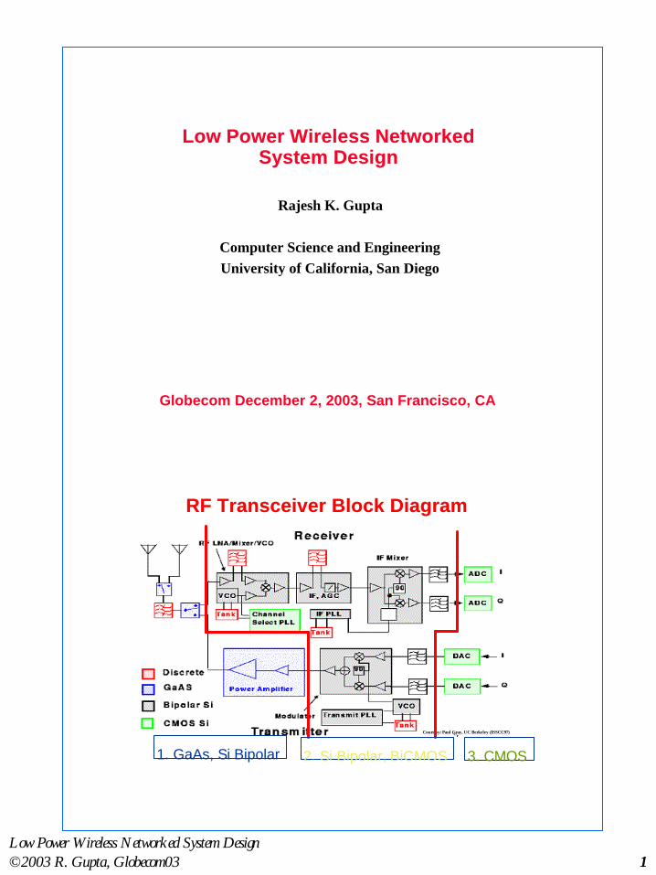
RF Transceiver Block DiagramRF Transceiver Block Diagram
Courtesy: Paul Gray, UC Berkeley (ISSCC97)
1. GaAs, Si Bipolar 2. Si Bipolar, BiCMOS 3. CMOS

Low Power Wireless Networked System Design©2003 R. Gupta, Globecom03 2
Typical RF TransceiverTypical RF TransceiverImplementationImplementation
Courtesy: Paul Gray, UC Berkeley (ISSCC97)
UCB DECT CMOS Adaptive RXUCB DECT CMOS Adaptive RX
Courtesy: Rudell, et al, ISSCC’97
0.6 um CMOS, 7.5mm x 6.4mm die size.55dB image rejection, mostly from IR mixer.
198 mW power. RX gain max 78 dB, min 26 dB

Low Power Wireless Networked System Design©2003 R. Gupta, Globecom03 3
5
Wireless Systems DesignsWireless Systems Designs
l Key Driversn Relentless digitization of signals and systems
u high speed digital circuits, ADCs leading to IF (andeven RF) processing in digital domain, directconversion techniques
u complex communication algorithms and increasingavailable MIPS favor digital implementation
n Microelectronic advances in CMOS VLSIu (RF as well as base-band digital processing), MEMS
structures
Ü These trends are making it increasingly possible (and evencost effective) to build Wireless Systems on a Chip
6
Systems Engineering for Systems Engineering for SOCsSOCs
Example Problem: How to achieve high throughput in a SOC forwireless applications?
l Can select a modem sub-systemn that packs more bits/Hz, but it will tolerate less noise and be
less robust so that link throughput may not improvel Can increase transmit power in RF subsystem
n to improve robustness but this increases energy cost,reduces network capacity, and requires more expensiveanalog circuits (power amps)
l Can reduce bits/framen to tolerate higher bit error rates (BER) and provide more
robustness, but this may increase overhead and queuingdelays
l Can increase precision in digital modemn to reduce noise, but this leads to wider on-chip busses and
more power consumption
Ü IC designer is also a communications system designer.
MultipleAccessMultiplex
SourceCoder
SourceCoder
ChannelCoder Modulator Power
Amplifier
Radio
Channel
MultipleAccessDemultiplex
SourceDecoder
SourceDecoder
ChannelDecoder
Demodulator& Equalizer
RFFilter
Sou
rce
Des
tin
atio
n
Carrier fc
Carrier fc
“Highly variable b/w”“Random & Noisy”
“Limited b/w”
“Spurious disconnections”
transmittedsymbol stream
received (corrupted)symbol stream
antenna
antenna

Low Power Wireless Networked System Design©2003 R. Gupta, Globecom03 4
7
Wireless NES System CharacteristicsWireless NES System Characteristics
l Wirelessn limited bandwidth, high latency (3ms-100ms)n variable link quality and link asymmetry due to noise,
interference, disconnectionsn easier snoopingÜneed for more signal and protocol processing
l Mobilityn causes variability in system design parameters:
connectivity, b/w, security domains, location awarenessÜneed for more protocol processing
l Portabilityn limited capacities (battery, CPU, I/O, storage, dimensions)Üneed for energy efficient signal and protocol processing
8
Energy Availability GrowthEnergy Availability Growthlimited to 2-3% per year
Proc
esso
r (M
IPS)
Hard
Disk
(cap
acity
)
Memory
(capaci
ty)
Battery (energy stored)
0 1 2 3 4 5 6
16x
14x
12x
10x
8x
6x
4x
2x1xIm
prov
emen
t (c
ompa
red
to y
ear
0)
Time (years)
è Need to be energy efficient at all levels and in all tasks.
J. Rabaey, BWRC

Low Power Wireless Networked System Design©2003 R. Gupta, Globecom03 5
9
Processor MHz Year SPECint-95 WattsP54VRT (Mobile) 150 1996 4.6 3.8P55VRT (Mobile MMX) 233 1997 7.1 3.9PowerPC 603e 300 1997 7.4 3.5PowerPC 604e 350 1997 14.6 8PowerPC 740 (G3) 300 1998 12.2 3.4PowerPC 750 (G3) 300 1998 14 3.4Mobile Celeron 333 1999 13.1 8.6
Computational EfficiencyComputational Efficiency
l Speed power efficiency has indeedgone up
n 10x / 2.5 years for µPs and DSPs in1990s
u between 100 mW/MIP to 1mW/MIP since 1990
n IC processes have provided 10x / 8years since 1965
n rest from power conscious ICdesign in recent years
l Lower power for a given function &performance
n e.g. 1.6x / year reduction sinceearly 80s for DSPs (source TI)
l Most optimistic projections at beststop at 60 pJ/op (about 20X)
è However, circuit gains arenearing a plateau
n circuit tricks & voltagescaling provided a largepart of the gains
l while energy needs(functionality, speed) continueto climb
n 10x increases: in gate count(7 years); in frequency (9years)
10
Efficiency in CommunicationsEfficiency in Communications
l Power Efficiency (or Energy Efficiency) ηP = Eb/N0
n ratio of signal energy per bit to noise power spectral density requiredat the receiver for a certain BER
n high power efficiency requires low (Eb/N0) needed for a given BER
l Bandwidth Efficiency ηB = bit rate / bandwidth = Rb/W bps/hzn ratio of throughput data rate to bandwidth occupied by the modulated
signal (typically range from 0.33 to 5)
l Often a trade-off between the twon e.g. for a given BER
u adding FEC reduces ηB but reduces required ηP
u modulation schemes with larger # of bits per symbol have higherηB but also require higher ηP
n for PSK, QAM, generally higher bw efficiency decreases powerefficiency

Low Power Wireless Networked System Design©2003 R. Gupta, Globecom03 6
11
Effect of Improving BW efficiencyEffect of Improving BW efficiencythrough modulationthrough modulation
l For a 10-5 BER and fixed transmission BW
#bits persymbol
Power PenaltyFactor
Bit-rate GainFactor
Energy PenaltyFactor
2 1 1 1
4 2 2 1
8 4.7 3 1.56
16 10 4 2.5
32 20.7 5 4.1
64 42 6 7
12
Communication vs. ComputationCommunication vs. Computation
l Computation cost (2004 projected): 60 pJ/opl Minimum thermal energy for communications:
n 20 nJ/bit @ 1.5 GHz for 100 mu equivalent of 300 ops
n 2 nJ/bit @ 1.5 GHz for 10 mu equivalent of 0.03 ops
è significant processing versus communication tradeoff
l Computation cost (2004 projected): 60 pJ/opl Minimum thermal energy for communications:
n 20 nJ/bit @ 1.5 GHz for 100 mu equivalent of 300 ops
n 2 nJ/bit @ 1.5 GHz for 10 mu equivalent of 0.03 ops
è significant processing versus communication tradeoff
J. Rabaey, BWRC

Low Power Wireless Networked System Design©2003 R. Gupta, Globecom03 7
13
The NeedThe Need
l Power consumption, energy efficiency is a system leveldesign concern
n efficiency in computation, communication andnetworking subsystems
l The energy/power tradeoffs cut acrossn all system layers: circuit, architecture, software,
algorithmsn need to choose the right metric
l Power awareness goes beyond low power concernsn make tradeoffs against performance, quality measures
against application constraints
14
Presentation Focus: Techniques & ToolsPresentation Focus: Techniques & Tools
Goal: A systems view of integrated wireless system design for low power.n Design technology challenges in networked SOCs
u Two views of Networked SOCsäcompositional (or ASIC view)äarchitectural (or network-centric view)
u Scope and categories of design tools for NSOCsu Network architectural modelingu System-level composition through OO mechanisms
n Design of Wireless Systemsn Example Platform: TI/OMAPn Energy awareness: ARM platform
This talk will NOT describe:n detailed algorithms used in CAD toolsn theory of radio and communications system designn detailed architecture of any wireless communication system.
Low Power Wireless Networked System Design©2003 R. Gupta, Globecom03 8
15
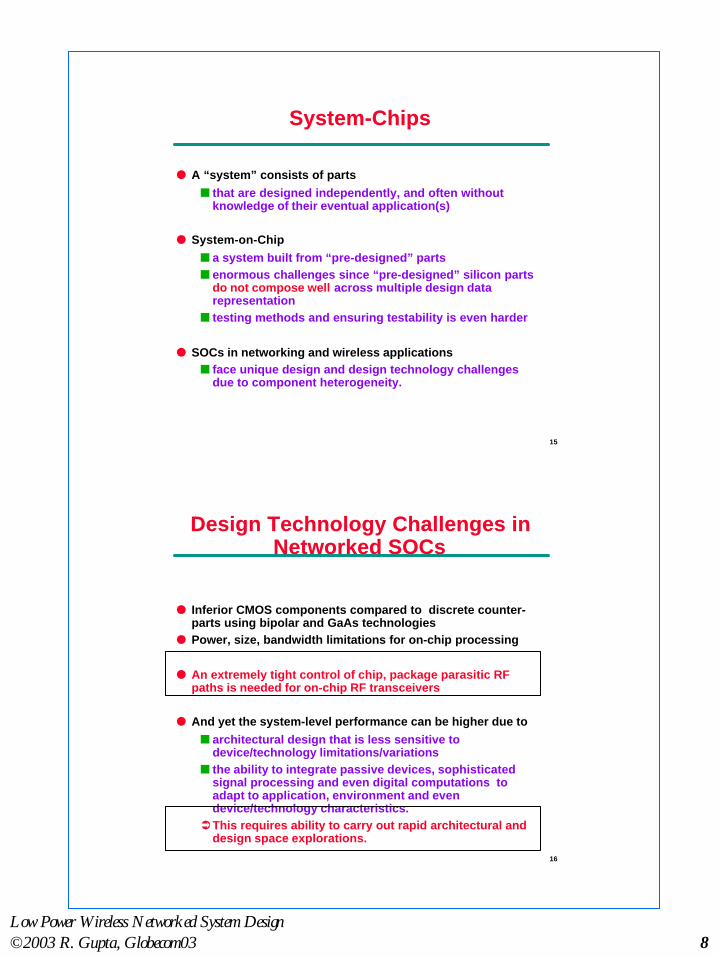
System-ChipsSystem-Chips
l A “system” consists of partsn that are designed independently, and often without
knowledge of their eventual application(s)
l System-on-Chipn a system built from “pre-designed” partsn enormous challenges since “pre-designed” silicon parts
do not compose well across multiple design datarepresentation
n testing methods and ensuring testability is even harder
l SOCs in networking and wireless applicationsn face unique design and design technology challenges
due to component heterogeneity.
16
Design Technology Challenges inDesign Technology Challenges inNetworked SOCsNetworked SOCs
l Inferior CMOS components compared to discrete counter-parts using bipolar and GaAs technologies
l Power, size, bandwidth limitations for on-chip processing
l An extremely tight control of chip, package parasitic RFpaths is needed for on-chip RF transceivers
l And yet the system-level performance can be higher due ton architectural design that is less sensitive to
device/technology limitations/variationsn the ability to integrate passive devices, sophisticated
signal processing and even digital computations toadapt to application, environment and evendevice/technology characteristics.ÜThis requires ability to carry out rapid architectural and
design space explorations.

Low Power Wireless Networked System Design©2003 R. Gupta, Globecom03 9
17
How will we design theseHow will we design thesesystem-chips?system-chips?
l There are two distinct views of NSOC:n Compositional or ASIC view
u SOC design is a ultimately an integrated circuitdesign
u demands from mother-nature must be met.
n Network centric viewu Protocol and communication functions are central to
chip functionalityä“The really hard part is figuring out how to relate sub-system
performance enhancements to end-user performance.”ä“I find the hardest part to be making trade-offs so as to
optimize across the various layers (physical, link, network,transport, application) of the communication system. Weneed tools and techniques to co-design these layers,instead of separate black-box optimizations.”
l Regardless of the view, one fact is abundantly clear that:n IC Designer is also a networked systems designer.
Application
OS & Middleware
TransportCODECActuatorSensor
Peripherals Network
MAC/Link
Physical
Application
OS & Middleware
Transport CODECActuatorSensor
PeripheralsNetwork
MAC/Link
Physical
PROTOCOLS
Flow of bits
18
Compositional View: ASICCompositional View: ASIC
RF & IF Transceiver
Baseband Processing
CustomASIC
Logic
AlgorithmAccelerationCoprocessors
DSP Core
RAM/ROM
WirelessProtocol
ProcessorRAMROM
DRAM
Network/Host/PeripheralInterface
(Microcontroller)
RF Design
Signal Processing Algorithms
Application
Protocol design
Interface design

Low Power Wireless Networked System Design©2003 R. Gupta, Globecom03 10
19
Network Systems ViewNetwork Systems View
Application
OS & Middleware
Transport
Network
MAC/Link
Physical
CODECActuatorSensor
Peripherals
DSP
Application & architecture modeling
Network architecture modelingProtocol Design
Protocol Design
RF Design
Algorithm design
20
ASIC & Network ModelsASIC & Network Models
l Complementary modelsn ASIC models focus on “node” implementationn Network model keeps “multi-node” system view
l Example: Synopsys Protocol Compiler, NS models.
l “Theoretically” both models can support either viewl Designers often need the ability
n to tradeoff across layers (easier in ASIC models) whilen keeping the system view (easier in network models).
l Hence, a convergence in works on integration of ASIC andNetwork models
n MIL3 OPNET, Cadence Bones, Diablon HP EEsof’s ADS, AnSoft HFSS, Cadence Allegro,
Anadigics, White Eagle DSP, ...

Low Power Wireless Networked System Design©2003 R. Gupta, Globecom03 11
21
Scope of NSOC Design ToolsScope of NSOC Design Tools
l Design of single-chip systems with radio transceiversrequires tools
n to explore new architectures containing heterogeneouselements
n to explore circuit design containing analog/digital,active/passive components (mixed signal design)
n to accurately estimate parasitic effects, package effectsl Typically mixed-system design entails
n antennae designn network design: interference, user mobility, access to
shared resourcesn algorithmic simulationsn protocol designn circuit design, layout and estimation tools
22
Categories of Design ToolsCategories of Design Tools
l Architectural design toolsn network, protocol simulationsn algorithmic simulations, partitioning and mapping tools
l Design environment toolsn encapsulated libraries, library management for design
componentsl Module design
n low noise integrated frequency synthesizersn base-band over-sampled data convertersn design of RF, analog, digital VLSI modules
l Modeling, characterization and validation toolsn characterization of mixed-mode designs, RF coupling
paths, EMIn simultaneous modeling, design and optimization of
antenna, passive RF filter, RF amp, RF receiver, poweramp. components

Low Power Wireless Networked System Design©2003 R. Gupta, Globecom03 12
23
Network Architectural DesignNetwork Architectural Design
or “behavioral design” for wireless systems
l Design network architecturen point-to-point, cellular, etc
l Design protocolsn specificationn verification at various levels: link, MAC, physical
l Tools in this categoryn Matlab, Ptolemy (and likes)n network, protocol simulators
l Tools are designed for simulations specific to a design layer:n simulation tools for algorithm developmentn simulation tools for network protocolsn simulation tools for circuit design, hardware
implementation, etc.
24
Network Architecture Modeling: NSNetwork Architecture Modeling: NS
l Developed under the Virtual Internet Testbed (VINT) project(UCB, LBL, USC/ISI, Xerox PARC)
l Captures network nodes, topology and provides efficientevent driven simulations with a number of “schedulers”
l Interpreted interface forn network configuration, simulation setupn using existing simulation kernel objects such as
predefined network linksl Simulation model in C++ for
n packet processingn changing models of existing simulation kernel classes,
e.g., using a special queuing discipline.

Low Power Wireless Networked System Design©2003 R. Gupta, Globecom03 13
25
Example:Example:A 4-node system with 2 “agents”, a traffic generatorA 4-node system with 2 “agents”, a traffic generator
n0UDP
n1TCP
n2n3
Sink
ftp
set ns [new Simulator]set f [open out.tr w]$ns trace-all $fset n0 {$ns node}set n1 {$ns node}set n2 {$ns node}set n3 {$ns node}$ns duplex-link $no $n2 5Mb 2ms DropTail$ns duplex-link $n1 $n2 5Mb 2ms DropTail$ns duplex-link $n2 $n3 1.5Mb 10ms DropTailset udp0 [newagent/UDP]$ns attach-agent $n0 $udp0set cbr0 [newapplication/Traffic/CBR]$cbr0 attach-agent $udp0..$ns at 3.0 “finish”proc finish () {
…}$ns run
l “Agents” are network endpoints where network-layer packetsare constructed or consumed.
26
NS v2 Implementation and UseNS v2 Implementation and Use
l A “Split-level” simulator consisting ofn C++ compiled simulation enginen Object Tcl (Otcl) interpreted front end
l Two class hierarchies (compiled, interpreted) with 1-1correspondence between the classes
n C++ compiled class hierarchyu allows detailed simulations of protocols that need
use of a complete systems programming language toefficiently manipulate bytes, packet headers,algorithms over large and complex data types
u runtime simulation speedn Otcl interpreted class hierarchy
u to manage multiple simulation “splits”u important to be able to change the model and rerun
l NS pulls off this trick by providing tclclass that providesaccess to objects in both hierarchies.

Low Power Wireless Networked System Design©2003 R. Gupta, Globecom03 14
27
NS ImplementationNS Implementation
l Example:n Otcl objects that assemble, delay, queue.n Most routing is done in Otcln HTTP simulations with flow started in Otcl but packet
processing is done in C++l Passing results to and from the interpreter
n The interpreter after invoking C++ expects results back ina private variable tcl_->result
n When C++ invokes Otcl the interpreter returns the resultin tcl_->result
l Building simulationn Tclclass provides simulator with scripts to create an
instance of this class and calling methods to createnodes, topologies etc.
n Results in an event-driven simulator with 4 separateschedulers: FIFO (list); heap; calendar queue; real-time.
n Single threaded, no event preemption.
28
NS Usage: LAN nodesNS Usage: LAN nodes
l LAN and wireless links are inherently different from PTP linksdue to sharing and contention properties of LANs
n a network consisting of PTP links alone can not captureLAN contention properties
n a special node is provided to specify LANs
l LanNode captures functionality of three lowest layers in theprotocol stack, namely: link, MAC and physical layers.
n Specifies objects to be created for LL, INTF, MAC andPhysical channels.
n Example:$ns make- lan <nodelist> <bw> <delay> <LL> <ifq> <MAC> <channel> <phy>
$ns make- lan “$n1 $n2” $bw $delay LL queue/DropTail Mac/CSMA/CD.
n Creates a LAN with basic link-layer, drop-tail queue andCSMA/CD medium access control.
n1 n2
n3
n1 n2
n3
LAN
The LAN node collects allthe objects shared on the
LAN.
Low Power Wireless Networked System Design©2003 R. Gupta, Globecom03 15
29
node1
Q
LL
MAC
node2
Q
LL
MAC
node3
Q
LL
MAC
Channel MAC classifier
LL
MAC
Phy
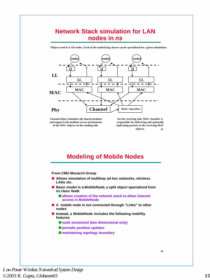
Channel object simulates the shared mediumand supports the medium access mechanisms
of the MAC objects on the sending side.
On the receiving side, MAC classifier isresponsible for delivering and optionallyreplicating packets to the receiving MAC
objects.
Network Stack simulation for LANNetwork Stack simulation for LANnodes in nodes in nsns
Objects used in LAN nodes. Each of the underlying classes can be specialized for a given simulation.
30
Modeling of Mobile NodesModeling of Mobile Nodes
From CMU Monarch Groupl Allows simulation of multihop ad hoc networks, wireless
LANs etc.l Basic model is a MobileNode, a split object specialized from
ns class Noden allows creation of the network stack to allow channel
access in MobileNodel A mobile node is not connected through “Links” to other
nodesl Instead, a MobileNode includes the following mobility
featuresn node movement (two dimensional only)n periodic position updatesn maintaining topology boundary

Low Power Wireless Networked System Design©2003 R. Gupta, Globecom03 16
31
Mobile NodesMobile Nodes
l As in wireline, the network “plumbing” is scripted in Otcll Four different routing protocols (or routing agents) are
availablen destination sequence distance vector (DSDV)n dynamic source routing (DSR)n Temporally ordered routing algorithm (TORA)n Adhoc on-demand distance vector (AODV)
l A mobile node creation results inn a mobile node with a specified routing agent, andn creation of a network stack consisting of
u LL (with ARP), INT Q, MAC, Network Interface with anantenna.
è Enables integrated event driven simulation of mixednetworks.
32
Mobile NodeMobile Node
Node/MobileNode instproc add-interface {channel pmodel lltype mactype qtype qlen iftype anttype } {
$self instvar arptable_ nifs_$self instvar netif_ mac_ ifq_ ll_set t $nifs_
set netif_($t) [new $iftype] ;# net-interfaceset mac_($t) [new $mactype] ;# mac layerset ifq_($t) [new $qtype] ;# interface queueset ll_($t) [new $lltype] ;# link layerset ant_($t) [new $anttype]..}
set topo [topography]$topo bind_flatgrid $opt(x) $opt(y)$node set x_ <x1>$node set y_ <y1>..$ns at $time $node setdest <x2> <y2> <speed>or$mobilenode start

Low Power Wireless Networked System Design©2003 R. Gupta, Globecom03 17
33
Network Simulation using OPNETNetwork Simulation using OPNET
l Commercially available from MIL3l Heterogenous models
n for networkn for noden for process
l Network, node, process editorsl Network models consist of node and link objectsl Nodes represent hardware, software subsystems
n processors, queues, traffic generators, RX, TXl Process models represent protocols, algorithms etc
n using state-transition diagramsl Simulation outputs typically include
n discrete event simulations, traces, first and second order statisticsn presented as time-series plots, histograms, prob. density,
scattergrams etc.
34
OPNET Wireless System ModelingOPNET Wireless System Modeling
l OPNET modeler with radio links and mobile nodesl Mobile nodes include three-dimensional position attributes
that can change dynamically as the simulation progresses.l Node motion can be scripted (position history) or by a
position control process.l Links modeled using a 13-stage model where each stage is a
function (in C)l Transmitter stages:
n Transmission delay model: time required fortransmission
n Link closure model: determine reachable receiversn Channel match model: determine which RX channel can
demodulate the signal (rest treat it as noise)n Transmitter antenna gain: computes gain of TX antenna
in the direction of the receivern Propagation delay model: time for propagation from TX to
RX.

Low Power Wireless Networked System Design©2003 R. Gupta, Globecom03 18
35
Link Model StagesLink Model Stages
l Receiver stages:n RX antenna gain: in the direction of the receivern Received power model: avg. received powern Background Noise Model: computes the in-band
background noise for a receiver channeln Interference noise model: typically total power of all
concurrent in-band transmissionn SNR model: SNR of transmission fragment based on the
ratio of received power and interference noisen BER model: computes mean BER over each constant
SNR fragment of the transmissionn Error Allocation Model: determines the number of bit
error in each fragment of the transmissionn Error Correction Model: determines whether the allocated
transmission errors can be corrected and if thetransmitted data should be forwarded in the node forhigher level processing.
36
Communications ToolboxCommunications Toolbox(MATLAB)(MATLAB)
l Part of the MATLAB DSP workshop suiten functionality models from MATLAB
u sources, sinks and error analysisu coding, modulation, multiple access blocks, etc.
n communication link models from SIMULINKu channel models: Rayleigh, Rician fading, noise
modelsl Good front-end simulations through vector processing
n handles data at different time-points in large vectorsn used in modeling physical layer component such as
modemsn useful in algorithm development and performance
analysisu for modulation, coding, synchronization,
equalization, filter design.
http://www.mathworks.com/products/communications/index.shtml

Low Power Wireless Networked System Design©2003 R. Gupta, Globecom03 19
37
Integrated ModelsIntegrated Models
l Package boundary is enlargingn analog/RF, digital baseband, applications, RTOS, DSP, …
l Hardware-type ‘behavioral’ modeling just does not cut itn Substantial networking, communications, infrastructure
software needs to be modeled as well.l Learning from practice
n People generally use C or C++ to model at system Leveln Typically performance model and ISA models are built
with C/C++Ü Why not ‘standardize’ use of C++ for system modeling
purposes?n We already do software, network modeling.
38
Enter Enter SystemCSystemC
l SystemC developed by Synopsys, Cowaren Initially Scenic project (Synopsys and UC Irvine)n SystemC-0.9 (Sept 1999) based on Scenicn SystemC-1.0 (Early 2000) performance enhancementsn SystemC-2.0 (mid 2001) – ideas from SpecC (UC Irvine)
incorporatedn SystemC-3.0 (yet to be released) – software APIs
l Other players that influenced SystemCn OCAPI library (IMEC Belgium)n Cynlib (FORTE Design Systems, formerly CynApps)n SpecCn SuperLOG (now SystemVerilog) from Coware (now
Synopsys)

Low Power Wireless Networked System Design©2003 R. Gupta, Globecom03 20
39
What Is SystemC?What Is SystemC?
l A C++ library that helps designers to use C++ tomodel/specify synchronous digital hardware
n Reactivity: waiting and watchingn Data types
l Built in simulation libraries (simulation kernel) that can beused to run a SystemC program
l Any C++ compiler can compile SystemCn Simulation is free in comparison to Verilog/VHDL
l A compiler that translates the “synthesis subset” of SystemCinto a netlist (Synopsys, FORTE)
l Language definition is publicly availablen (Open SystemC Initiative or OSCI)
l Libraries are freely distributedl Compiler is an expensive commercial product
40
Quick OverviewQuick Overview
l A SystemC program consists of module definitions plus atop-level function that starts the simulation
l Modules contain processes (C++ methods) and instances ofother modules
l Ports on modules define their interfacen Rich set of port data types (hardware modeling, etc.)
l Signals in modules convey information between instancesl Clocks are special signals that run periodically and can
trigger clocked processesl Rich set of numeric types (fixed and arbitrary precision
numbers)

Low Power Wireless Networked System Design©2003 R. Gupta, Globecom03 21
41
SystemCSystemC Architecture Architecture
Source: Stuart Swan, Cadence/OSCI
42
Modules and PortsModules and Ports
Modules:l Hierarchical entityl Similar to Verilog’s modulel Actually a C++ class definitionl Simulation involves
n Creating objects of this classn They connect themselves togethern Processes in these objects (methods)
are called by the scheduler (simulationkernel) to perform the simulation
Ports:l Define the interface to each modulel Entities through which data is
communicatedl Port consists of a direction
n input sc_inn output sc_outn bidirectional sc_inout
l and any C++ or SystemC typeSignals:
n Information transfer within a module.
SC_MODULE(mymod) { /* port definitions */ /* signal definitions */ /* clock definitions */
/* storage and state variables */
/* process definitions */
SC_CTOR(mymod) { /* Instances of processes and modules */ }}; SC_MODULE(mymod) {
/* port definitions */ sc_signal<sc_uint<32> > s1, s2; sc_signal<bool> reset;
/* … */ SC_CTOR(mymod) { /* Instances of modules that connect
to the signals */ }};

Low Power Wireless Networked System Design©2003 R. Gupta, Globecom03 22
43
ProcessesProcesses
l Procedural code with the ability to suspend and resume
l Methods of each module class
l Three types:n METHOD
u Usually Models combinational logicu Triggered in response to changes on inputs
n THREADu Usually Models testbenches
n CTHREADu Usually Models synchronous FSMs
44
METHOD ProcessesMETHOD Processes
SC_MODULE(onemethod) { sc_in<bool> in; sc_out<bool> out;
void inverter();
SC_CTOR(onemethod) {
SC_METHOD(inverter); sensitive(in);
}};
Process is simply amethod of this class
Instance of thisprocess created
and made sensitiveto an input

Low Power Wireless Networked System Design©2003 R. Gupta, Globecom03 23
45
METHOD ProcessesMETHOD Processes
l Invoked once every time input “in” changes
l Runs to completion: should not contain infinite loopsn No mechanism for being preempted
void onemethod::inverter() { bool internal; internal = in; out = ~internal;}
Read a value from the port
Write a value to anoutput port
46
THREAD ProcessesTHREAD Processes
l Triggered in response to changes on inputs
l Can suspend itself and be reactivatedn Method calls wait to relinquish control
n Scheduler runs it again later
l Designed to model just about anything

Low Power Wireless Networked System Design©2003 R. Gupta, Globecom03 24
47
THREAD ProcessesTHREAD Processes
SC_MODULE(onemethod) { sc_in<bool> in; sc_out<bool> out;
void toggler();
SC_CTOR(onemethod) {
SC_THREAD(toggler); sensitive << in; }
};
Process is simply amethod of this class
Instance of thisprocess created
alternate sensitivitylist notation
48
THREAD ProcessesTHREAD Processes
l Reawakened whenever an input changes
l State saved between invocations
l Infinite loops should contain a wait()
void onemethod::toggler() { bool last = false; for (;;) { last = in; out = last; wait(); last = ~in; out = last; wait(); }}
Relinquish controluntil the nextchange of a signalon the sensitivitylist for this process

Low Power Wireless Networked System Design©2003 R. Gupta, Globecom03 25
49
CTHREAD ProcessesCTHREAD Processes
l Triggered in response to a single clock edge
l Can suspend itself and be reactivatedn Method calls wait to relinquish controln Scheduler runs it again later
l Designed to model clocked digital hardware
50
CTHREAD ProcessesCTHREAD Processes
SC_MODULE(onemethod) { sc_in_clk clock; sc_in<bool> trigger, in; sc_out<bool> out;
void toggler();
SC_CTOR(onemethod) {
SC_CTHREAD(toggler, clock.pos()); }
};
Instance of thisprocess created andrelevant clock edgeassigned

Low Power Wireless Networked System Design©2003 R. Gupta, Globecom03 26
51
SystemC Built-in TypesSystemC Built-in Types
l sc_bit, sc_logic
n Two- and four-valued single bitl sc_int, sc_unint
n 1 to 64-bit signed and unsigned integersl sc_bigint, sc_biguint
n arbitrary (fixed) width signed and unsigned integersl sc_bv, sc_lv
n arbitrary width two- and four-valued vectorsl sc_fixed, sc_ufixed
n signed and unsigned fixed point numbers
52
SystemC SemanticsSystemC Semantics
l Cycle-based simulation semanticsl Resembles Verilog, but does not allow the modeling of
delaysl Designed to simulate quickly and resemble most
synchronous digital logic

Low Power Wireless Networked System Design©2003 R. Gupta, Globecom03 27
53
ClocksClocks
l The only thing in SystemC that has a notion of real time
l Triggers SC_CTHREAD processesn or others if they decided to become sensitive to clocks
54
ClocksClocks
l sc_clock clock1(“myclock”, 20, 0.5, 2, false);
20
2
0.5 of20
Initial value isfalse
Time Zero
Low Power Wireless Networked System Design©2003 R. Gupta, Globecom03 28
55
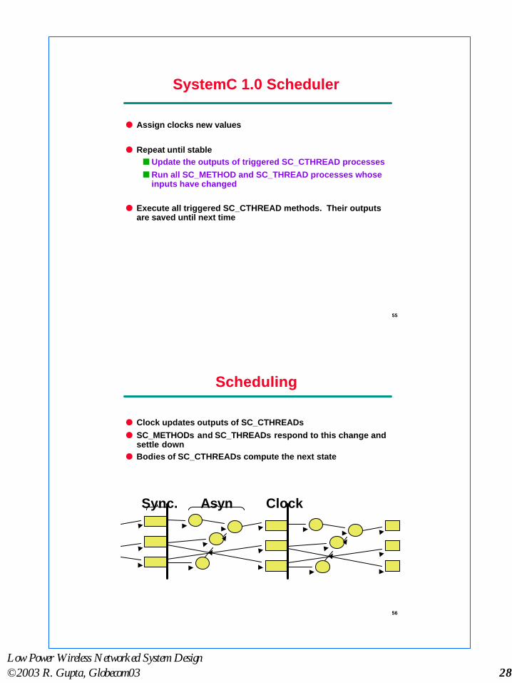
SystemC 1.0 SchedulerSystemC 1.0 Scheduler
l Assign clocks new values
l Repeat until stablen Update the outputs of triggered SC_CTHREAD processesn Run all SC_METHOD and SC_THREAD processes whose
inputs have changed
l Execute all triggered SC_CTHREAD methods. Their outputsare saved until next time
56
SchedulingScheduling
l Clock updates outputs of SC_CTHREADsl SC_METHODs and SC_THREADs respond to this change and
settle downl Bodies of SC_CTHREADs compute the next state
Sync. Asyn Clock

Low Power Wireless Networked System Design©2003 R. Gupta, Globecom03 29
57
Recap: SC can connect toRecap: SC can connect to‘anything’‘anything’
l SC_METHODn Designed for modeling purely functional behaviorn Sensitive to changes on inputsn Does not save state between invocations
l SC_THREADn Designed to model anythingn Sensitive to changesn May save variable, control state between invocations
l SC_CTHREADn Models clocked digital logicn Sensitive to clock edgesn May save variable, control state between invocations
58
SystemCSystemC and NS-2 and NS-2
Fummi et al in DAC 2003l Integration possible
because of DE MOCused in both
n Different notion ofevents and eventhandling
l Various levels ofsimulator integration
n Packet level tointegrated kernels
l Time Synchronizationis usually thetoughest problem
n Various co-simulationaproaches

Low Power Wireless Networked System Design©2003 R. Gupta, Globecom03 30
59
Experiment: 802.11 +MAC in SCExperiment: 802.11 +MAC in SC
60
Complete Models ThroughComplete Models ThroughIntegration With ISSIntegration With ISS
l Too frequent communication with ISS can slow down thesystem simulation (usually through IPC)
l ISS ‘wrapper’ can be SystemC (interface) modules (IF)
Source: Benini, Drago, Fummi, Computer 03

Low Power Wireless Networked System Design©2003 R. Gupta, Globecom03 31
61
“Platform-based” Simulations“Platform-based” Simulations
l Multiple simulators running simultaneouslyn Many attempts are reducing need for coordination and
improving simulation efficiencyu E.g., using bus functional model to advance internal
progressäStill maintain some level of “cycle accuracy”äA similar reasoning on “bit true” accuracy
å(movement toward TLM which basically usefunction calls as component interfaces,instead of signals)
n Consider, for instance, integration with processor ISSmodels
u Can be “linked” through IPC, remote activation,shared memory accesses
u Can be “embedded” through class extensionsäOften need a greater access to simulator source
n Currently about 100K cycles/sec speed on HP platforms
62
Integrating ISS: How C++ Can Help?Integrating ISS: How C++ Can Help?
l A close linking possible by embedded ISS within SystemCsimulator as a C++ cloass
l Use a ‘wrapper’ module that instantiates ‘core’ object,launches its simulation, and ‘traps’ shared accesses
l Example:n Wrapper instances CPU objectn Starts ISS simulation through SC_THREAD
u Run method continues until a memory accessäThat triggeres Bus Interface process in SystemCäGenerating cycle accurate bus signals outside
the CPU wrapper

Low Power Wireless Networked System Design©2003 R. Gupta, Globecom03 32
63
ExampleExample
Source: Benini, Drago, Fummi, Computer 03
64
ComponentIntegration, CIL
Split-Level Interface/BIDL
C++, SystemC
System designer
Com
piledInterpreted
Going Forward: CCFGoing Forward: CCF
l Component Composition Frameworksl A composition environment
n Built upon existing class libraries, toadd a software layer for manipulationand configuration of C++ IP models
n Ease software module connectivityn Run-time environment structure
l SW Architecture That Enablesn composition of structural and
functional info.n Notions of component substitutability
based on type theory extensions.
ÜÜ modeling of the application and themodeling of the application and theplatformplatform
http://mesl.ucsd.edu

Low Power Wireless Networked System Design©2003 R. Gupta, Globecom03 33
65
Language and Run-time LayersLanguage and Run-time Layers
Interpreter
BIDL Compiler
Split Level Interfaces
GCC Compiled objects
Language Tools Run-time structure
GCC
Introspection
BIDL
C++
CIL
SLI/Typesystem
extension
Reflection
66
SummarySummary
l Design tools offerings for on-chip networked and wirelesssystems are an area of growing importance due to inherentcomplexity of on-chip design and multi-level tradeoffs
l Wireless system design tools are strongly influenced by thelayer at which the design is being done
l System modeling tools are quite common and advanced
l Design environments, circuit design tools lag significantlybehind the design practice
l Current efforts at “integrated” design (exploration)environments.

Low Power Wireless Networked System Design©2003 R. Gupta, Globecom03 34
67
ReferencesReferences
l Models of computation:n http://ptolemy.eecs.berkeley.edu
l Language and methodology :n SpecC: http://www.ics.uci.edu/~specc
n OCAPI: http://www.imec.be/ocapil Languages :
n SystemC: http://www.systemc.orgn CynApps: http://www.cynapps.comn CoWare: http://www.coware.com
n Objective VHDL:l Language semantics:
n R. Gupta and S. Liao, Using a programming language for digital systemdesign, IEEE D&T April-June 97
l Interface based design:
n Alberto DAC97 Paperl VSIA system level design workgroup: http://www.vsi.orgl System level issue: Gajski’s silicon compilation and blue books
l Software design pattern bookl Architecture description language: www.ics.uci.edu/~aces/expression
68
AcknowledgementsAcknowledgements
l Sandeep Shukla, Virginia Techl Mani Srivastava, UCLA
Top Related