


Languages
Pages
Legal


Siemens ST 70 · 2015
2
Brochures
For brochures serving as selection guides for SIMATIC products refer to:
www.siemens.com/simatic/printmaterial
2/2 Introduction
2/3 LOGO! modular2/3 LOGO! modular basic variants2/9 SIPLUS LOGO! modular basic variants2/11 LOGO! modular pure variants2/15 SIPLUS LOGO! modular pure variants2/17 LOGO! modular expansion modules2/27 SIPLUS LOGO! modular expansion
modules
2/30 LOGO! modular communication modules2/30 LOGO! CM EIB/KNX communication
modules2/31 LOGO! CSM unmanaged2/33 LOGO! CMR (wireless communication)2/37 AS-Interface connection for LOGO!
2/38 LOGO!Power
2/49 SIPLUS LOGO!Power
2/50 LOGO!Contact
2/51 LOGO! Software
2/52 SIPLUS add-ons2/52 SIPLUS LOGO! PROM
LOGO! logic module
ST70_Kap02_EN.book Seite 1 Mittwoch, 13. Mai 2015 8:41 08
© Siemens AG 2015

2/2 Siemens ST 70 · 2015
2
LOGO! logic moduleIntroduction
LOGO! logic module
■ Overview
LOGO! logic module• The compact, easy-to-use and low-cost solution for simple
control tasks• Compact, easy to operate, universally applicable without
accessories• "All in one": Integrated display and operator panel• 36 different functions can be connected at the click of a button
or by means of PC software; up to 130 times over• LOGO! 8: 38 / 43 different functions can be linked at the press
of a button or using PC software; up to 200/400 times• Functions are easily changed at the press of a key. No more
time-consuming rewiring
SIPLUS LOGO!• The controller for use in the toughest environmental conditions• With extended temperature range from -40/-25 °C to +70 °C • Suitable for medial exposure (harmful gas atmosphere)• Condensation permissible• With the proven PLC technology of LOGO!• Easy to handle, program, maintain, and service• Ideal for use in automotive engineering, environmental
engineering, mining, chemical plants, material handling, food industry, etc.
Accessories:• The front panel mounting set also allows simple and reliable
installation of the logic modules in front panels; IP65 protection is thus possible.
• In order to ensure dependable operation of SIPLUS devices supplied by the battery in conjunction with combustion engines, it is necessary to put in a SIPLUS upmiter upstream device between the battery and the SIPLUS LOGO!.
For further information, please go to:
http://www.siemens.com/siplus-extreme
■ General technical specifications SIPLUS LOGO!
Ambient temperature range -40/-25 ... +70 °C
Conformal coating Coating of the printed circuit boards and the electronic components
Technical data The technical data of the standard product applies except for the ambient conditions.
Ambient conditions
Extended ambient conditions
• Relative to ambient temperature-atmospheric pressure-installation altitude
Tmin ... Tmax at 1080 hPa ... 795 hPa (-1000 m ... +2000 m) // Tmin ... (Tmax - 10K) at 795 hPa ... 658 hPa (+2000 m ... +3500 m) // Tmin ... (Tmax - 20K) at 658 hPa ... 540 hPa (+3500 m ... +5000 m)
Relative humidity
• With condensation, max. 100 %; Relative humidity, incl. condensation / frost permitted (no commissioning under condensation conditions)
Resistance
• against biologically active substances / conformity with EN 60721-3-3
Yes; Class 3B2 mold, fungus and dry rot spores (with the exception of fauna). The supplied connector covers must remain on the unused interfaces during operation!
• against chemically active substances / conformity with EN 60721-3-3
Yes; Class 3C4 incl. salt spray. The supplied connector covers must remain on the unused interfaces during operation!
• against mechanically active substances / conformity with EN 60721-3-3
Yes; Class 3S4 incl. sand, dust. The supplied connector covers must remain on the unused interfaces during operation!
ST70_Kap02_EN.book Seite 2 Mittwoch, 13. Mai 2015 8:41 08
© Siemens AG 2015
2/3Siemens ST 70 · 2015
2
LOGO! logic moduleLOGO! modular
LOGO! modular basic variants
■ Overview
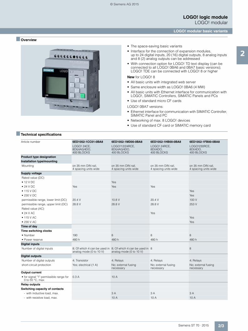
• The space-saving basic variants• Interface for the connection of expansion modules,
up to 24 digital inputs, 20 (16) digital outputs, 8 analog inputs and 8 (2) analog outputs can be addressed
• With connection option for LOGO! TD text display (can be connected to all LOGO! 0BA6 and 0BA7 basic versions); LOGO! TDE can be connected with LOGO! 8 or higher
New for LOGO! 8• All basic units with integrated web server• Same enclosure width as LOGO! 0BA6 (4 MW)• All basic units with Ethernet interface for communication with
LOGO!, SIMATIC Controllers, SIMATIC Panels and PCs• Use of standard micro CF cards
LOGO! 0BA7 versions:• Ethernet interface for communication with SIMATIC Controller,
SIMATIC Panel and PC• Networking of max. 8 LOGO! devices• Use of standard CF card or SIMATIC memory card
■ Technical specifications
Article number 6ED1052-1CC01-0BA8 6ED1052-1MD00-0BA8 6ED1052-1HB00-0BA8 6ED1052-1FB00-0BA8
LOGO! 24CE, 8DI(4AI)/4DO, 400 BLOCKS
LOGO!12/24RCE, 8DI(4AI)/4DO, 400 BLOCKS
LOGO! 24RCE, 8DI/4DO, 400 BLOCKS
LOGO!230RCE, 8DI/4DO, 400 BLOCKS
Product type designation
Installation type/mounting
Mounting on 35 mm DIN rail, 4 spacing units wide
on 35 mm DIN rail, 4 spacing units wide
on 35 mm DIN rail, 4 spacing units wide
on 35 mm DIN rail, 4 spacing units wide
Supply voltage
Rated value (DC)
• 12 V DC Yes
• 24 V DC Yes Yes Yes
• 115 V DC Yes
• 230 V DC Yes
permissible range, lower limit (DC) 20.4 V 10.8 V 20.4 V 100 V
permissible range, upper limit (DC) 28.8 V 28.8 V 28.8 V 253 V
Rated value (AC)
• 24 V AC Yes
• 115 V AC Yes
• 230 V AC Yes
Time of day
Time switching clocks
• Number 190 8 8 8
• Power reserve 480 h 480 h 480 h 480 h
Digital inputs
Number of digital inputs 8; Of which 4 can be used in analog mode (0 to 10 V)
8; Of which 4 can be used in analog mode (0 to 10 V)
8 8
Digital outputs
Number of digital outputs 4; Transistor 4; Relays 4; Relays 4; Relays
short-circuit protection Yes; electrical (1 A) No; external fusing necessary
No; external fusing necessary
No; external fusing necessary
Output current
• for signal "1" permissible range for 0 to 55 °C, max.
0.3 A 10 A
Relay outputs
Switching capacity of contacts
- with inductive load, max. 3 A 3 A 3 A
- with resistive load, max. 10 A 10 A 10 A
ST70_Kap02_EN.book Seite 3 Mittwoch, 13. Mai 2015 8:41 08
© Siemens AG 2015

2/4 Siemens ST 70 · 2015
2
■ Technical specifications (continued)
LOGO! logic moduleLOGO! modular
LOGO! modular basic variants
EMC
Emission of radio interference acc. to EN 55 011
• Limit class B, for use in residential areas
Yes; Radio interference suppression according to EN 55011, Limit Value Class B
Yes Yes Yes
Degree and class of protection
Degree of protection to EN 60529
• IP20 Yes Yes Yes Yes
Standards, approvals, certificates
CSA approval Yes Yes Yes Yes
UL approval Yes Yes Yes Yes
FM approval Yes Yes Yes Yes
Developed in accordance with IEC 61131
Yes Yes Yes Yes
according to VDE 0631 Yes Yes Yes Yes
Marine approval
• Marine approval Yes Yes Yes Yes
Ambient conditions
Ambient temperature in operation
• Min. 0 °C 0 °C 0 °C 0 °C
• max. 55 °C 55 °C 55 °C 55 °C
Dimensions
Width 71.5 mm 71.5 mm 71.5 mm 71.5 mm
Height 90 mm 90 mm 90 mm 90 mm
Depth 60 mm 60 mm 60 mm 60 mm
Article number 6ED1052-1MD00-0BA7 6ED1052-1FB00-0BA7
LOGO!12/24RCE, 8DI(4AI)/4DO, 400 BLOCKS LOGO! 230RCE, 8DI/4DO, 400 BLOCKS
Product type designation
Installation type/mounting
Mounting on 35 mm DIN rail, 6 spacing units wide on 35 mm DIN rail, 6 spacing units wide
Supply voltage
Rated value (DC)
• 12 V DC Yes
• 24 V DC Yes
• 115 V DC Yes
• 230 V DC Yes
permissible range, lower limit (DC) 10.8 V 100 V
permissible range, upper limit (DC) 28.8 V 253 V
Rated value (AC)
• 115 V AC Yes
• 230 V AC Yes
Time of day
Time switching clocks
• Number 333 333
• Power reserve 480 h 480 h
Digital inputs
Number of digital inputs 8; Of which 4 can be used in analog mode (0 to 10 V) 8
Digital outputs
Number of digital outputs 4; Relays 4; Relays
short-circuit protection No; external fusing necessary No; external fusing necessary
Relay outputs
Switching capacity of contacts
- with inductive load, max. 3 A 3 A
- with resistive load, max. 10 A 10 A
Article number 6ED1052-1CC01-0BA8 6ED1052-1MD00-0BA8 6ED1052-1HB00-0BA8 6ED1052-1FB00-0BA8
LOGO! 24CE, 8DI(4AI)/4DO, 400 BLOCKS
LOGO!12/24RCE, 8DI(4AI)/4DO, 400 BLOCKS
LOGO! 24RCE, 8DI/4DO, 400 BLOCKS
LOGO!230RCE, 8DI/4DO, 400 BLOCKS
ST70_Kap02_EN.book Seite 4 Mittwoch, 13. Mai 2015 8:41 08
© Siemens AG 2015
2/5Siemens ST 70 · 2015
2
■ Technical specifications (continued)
LOGO! logic moduleLOGO! modular
LOGO! modular basic variants
EMC
Emission of radio interference acc. to EN 55 011
• Limit class B, for use in residential areas
Yes; Radio interference suppression according to EN55011, Limit Value Class B
Yes; Radio interference suppression according to EN55011, Limit Value Class B
Degree and class of protection
Degree of protection to EN 60529
• IP20 Yes Yes
Standards, approvals, certificates
CSA approval Yes Yes
UL approval Yes Yes
FM approval Yes Yes
Developed in accordance with IEC 61131
Yes Yes
according to VDE 0631 Yes Yes
Marine approval
• Marine approval Yes Yes
Ambient conditions
Ambient temperature in operation
• Min. 0 °C 0 °C
• max. 55 °C 55 °C
Dimensions
Width 107 mm 107 mm
Height 90 mm 90 mm
Depth 55 mm 55 mm
Article number 6ED1052-1CC01-0BA6 6ED1052-1MD00-0BA6 6ED1052-1HB00-0BA6 6ED1052-1FB00-0BA6
LOGO! 24C, 8DI(4AI)/4DO, 200 BLOCKS
LOGO! 12/24RC, 8DI(4AI)/4DO, 200 BLOCKS
LOGO! 24RC, 8DI/4DO, 200 BLOCKS
LOGO! 230RC, 8DI/4DO, 200 BLOCKS
Product type designation
Installation type/mounting
Mounting on 35 mm DIN rail, 4 spacing units wide
on 35 mm DIN rail, 4 spacing units wide
on 35 mm DIN rail, 4 spacing units wide
on 35 mm DIN rail, 4 spacing units wide
Supply voltage
Rated value (DC)
• 12 V DC Yes
• 24 V DC Yes Yes Yes
• 115 V DC Yes
• 230 V DC Yes
permissible range, lower limit (DC) 20.4 V 10.8 V 20.4 V 100 V
permissible range, upper limit (DC) 28.8 V 28.8 V 28.8 V 253 V
Rated value (AC)
• 24 V AC Yes
• 115 V AC Yes
• 230 V AC Yes
Time of day
Time switching clocks
• Number 190 8 8 8
• Power reserve 80 h 80 h 80 h 80 h
Digital inputs
Number of digital inputs 8; Of which 4 can be used in analog mode (0 to 10 V)
8; Of which 4 can be used in analog mode (0 to 10 V)
8 8
Article number 6ED1052-1MD00-0BA7 6ED1052-1FB00-0BA7
LOGO!12/24RCE, 8DI(4AI)/4DO, 400 BLOCKS LOGO! 230RCE, 8DI/4DO, 400 BLOCKS
ST70_Kap02_EN.book Seite 5 Mittwoch, 13. Mai 2015 8:41 08
© Siemens AG 2015
2/6 Siemens ST 70 · 2015
2
■ Technical specifications (continued)
LOGO! logic moduleLOGO! modular
LOGO! modular basic variants
Digital outputs
Number of digital outputs 4; Transistor 4; Relays 4; Relays 4; Relays
short-circuit protection Yes; electrical (1 A) No; external fusing necessary
No; external fusing necessary
No; external fusing necessary
Output current
• for signal "1" permissible range for 0 to 55 °C, max.
0.3 A
Relay outputs
Switching capacity of contacts
- with inductive load, max. 3 A 3 A 3 A
- with resistive load, max. 10 A 10 A 10 A
EMC
Emission of radio interference acc. to EN 55 011
• Limit class B, for use in residential areas
Yes; Radio interference suppression according to EN 55011, Limit Value Class B
Yes Yes Yes
Degree and class of protection
Degree of protection to EN 60529
• IP20 Yes Yes Yes Yes
Standards, approvals, certificates
CSA approval Yes Yes Yes Yes
UL approval Yes Yes Yes Yes
FM approval Yes Yes Yes Yes
Developed in accordance with IEC 61131
Yes Yes Yes Yes
according to VDE 0631 Yes Yes Yes Yes
Marine approval
• Marine approval Yes Yes Yes Yes
Ambient conditions
Ambient temperature in operation
• Min. 0 °C 0 °C 0 °C 0 °C
• max. 55 °C 55 °C 55 °C 55 °C
Dimensions
Width 72 mm 72 mm 72 mm 72 mm
Height 90 mm 90 mm 90 mm 90 mm
Depth 55 mm 55 mm 55 mm 55 mm
Article number 6ED1052-1CC01-0BA6 6ED1052-1MD00-0BA6 6ED1052-1HB00-0BA6 6ED1052-1FB00-0BA6
LOGO! 24C, 8DI(4AI)/4DO, 200 BLOCKS
LOGO! 12/24RC, 8DI(4AI)/4DO, 200 BLOCKS
LOGO! 24RC, 8DI/4DO, 200 BLOCKS
LOGO! 230RC, 8DI/4DO, 200 BLOCKS
ST70_Kap02_EN.book Seite 6 Mittwoch, 13. Mai 2015 8:41 08
© Siemens AG 2015

2/7Siemens ST 70 · 2015
2
LOGO! logic moduleLOGO! modular
LOGO! modular basic variants
■ Ordering data Article No. Article No.
LOGO! 8 logic module
LOGO! 24CE 6ED1052-1CC01-0BA8
Supply voltage 24 V DC, 8 digital inputs 24 V DC, of which 4 can be used in analog mode (0 to 10 V), 4 digital outputs 24 V DC, 0.3 A, integrated time switch Ethernet interface; 400 function blocks can be interlinked,modular expansion capability
LOGO! 12/24RCE 6ED1052-1MD00-0BA8
Supply voltage 12...24 V DC, 8 digital inputs 12/24 V DC, of which 4 can be used in analog mode (0 to 10 V)4 relay outputs 10 A, integral time switch Ethernet interface; 400 function blocks can be interlinked, modular expansion capability
LOGO! 24RCE 6ED1052-1HB00-0BA8
Supply voltage 24 V AC/DC, 8 digital inputs 24 V AC/DC, 4 relay outputs 10 A, integral time switch Ethernet interface; 400 function blocks can be interlinked, modular expansion capability
LOGO! 230RCE 6ED1052-1FB00-0BA8
Supply voltage 115...230 V AC/DC, 8 digital inputs 115...230 V AC/DC, 4 relay outputs 10 A, integral time switch Ethernet interface; 400 function blocks can be interlinked, modular expansion capability
LOGO! 7 logic module
LOGO! 12/24RCE logic module 6ED1052-1MD00-0BA7
Supply voltage 12/24 V DC, 8 digital inputs 12/24 V DC, of which 4 can be used in analog mode (0 to 10 V)4 relay outputs 10 A, integral time switch; 400 function blocks can be interlinked,Ethernet interface,modular expansion capability
LOGO! 230RCE logic module 6ED1052-1FB00-0BA7
115/230 V AC/DC supply voltage, 8 digital inputs 115/230 V AC/DC, 4 relay outputs 10 A, integral time switch; 400 function blocks can be interlinked, Ethernet interface, modular expansion capability
LOGO! 6 logic module
LOGO! 24C logic module 6ED1052-1CC01-0BA6
24 V DC supply voltage, 8 digital inputs 24 V DC, of which 4 can be used in analog mode (0 to 10 V), 4 digital outputs 24 V DC, 0.3 A, integrated time switch; 200 function blocks can be interlinked,modular expansion capability
LOGO! 12/24RC logic module 6ED1052-1MD00-0BA6
12/24 V DC power supply, 8x 12/24 V DC digital inputs, of which 4 can be used in analog mode (0 to 10 V)4x 10 A relay outputs, integral time switch; 200 function blocks can be interlinked,modular expansion capability
LOGO! 24RC logic module 6ED1052-1HB00-0BA6
24 V AC/DC power supply, 8x 24 V AC/DC digital inputs, 4x 10 A relay outputs, integral time switch; 200 function blocks can be interlinked,modular expansion capability
LOGO! 230RC logic module 6ED1052-1FB00-0BA6
115/230 V AC/DC power supply, 8x 115/230 V AC/DC digital inputs, 4x 10 A relay outputs, integral time switch; 200 function blocks can be interlinked, modular expansion capability
Accessories for LOGO! 8
LOGO! 8 text display HMI 6ED1055-4MH00-0BA1
6-line text display, can be connected to all LOGO! 8 Basic and Pure versions, with 2 Ethernet interfaces; including installation accessories.
Requires additional 12 V DC or 24 V AC/DC power supply
LOGO!Soft Comfort V8 6ED1058-0BA08-0YA1
For programming on the PC in LAD/FBD; executes on Windows 8, 7, XP, Linux and Mac OSX; on DVD
LOGO!Soft Comfort V8 Upgrade 6ED1058-0CA08-0YE1
Upgrade from V1.0 to V8, on DVD
ST70_Kap02_EN.book Seite 7 Mittwoch, 13. Mai 2015 8:41 08
© Siemens AG 2015

2/8 Siemens ST 70 · 2015
2
■ Ordering data Article No. Article No.
LOGO! logic moduleLOGO! modular
LOGO! modular basic variants
LOGO! 8 Starter Kits
In TANOS Box, with LOGO! 8, LOGO! Soft Comfort V8, WinCC Basic V13, Ethernet cable
LOGO! 8 12/24 V Starter Kit 6ED1057-3BA00-0AA8
With LOGO! 12/24RCE, LOGO! Power 24 V 1.3 A
LOGO! 8 230V Starter Kit 6ED1057-3BA02-0AA8
With LOGO! 230RCE
LOGO! 8 TDE Starter Kit 6ED1057-3BA10-0AA8
With LOGO! 12/24RCEO, LOGO! Power 24 V, 1.3 A, LOGO! TDE
LOGO! 8 KP300 Basic Starter Kit 6AV2132-0HA00-0AA1
With LOGO! 12/24RCE, LOGO! Power 24 V 1.3 A, KP300 Basic mono PN
LOGO! 8 KTP400 Basic Starter Kit 6AV2132-0KA00-0AA1
With LOGO! 12/24RCE, LOGO! Power 24 V 1.3 A, KTP400 Basic
LOGO! 8 KTP700 Basic Starter Kit 6AV2132-3GB00-0AA1
With LOGO! 12/24RCE, LOGO! Power 24 V 1.3 A, KTP700 Basic
Accessories for LOGO! 6, LOGO! 7
LOGO! TD text display 6ED1055-4MH00-0BA0
4-line text display, can be connected to all LOGO! 0BA6 Basic and Pure versions, including connecting cable
SIPLUS LOGO! TD text display 6AG1055-4MH00-2BA0
(extended temperature range -10 ... +60 °C and medial loading)
4-line text display, can be connected to all LOGO! Basic and Pure versions as of -0BA6, including connecting cable
LOGO! Memory Card 6ED1056-1DA00-0BA0
Program module for copying, with know-how protection
LOGO! battery card 6ED1056-6XA00-0BA0
Battery module for backing up the integral real-time clock (not LOGO! 24)
LOGO! memory/battery card 6ED1056-7DA00-0BA0
Combined program and battery module, with know-how protection and backup of the integral real-time clock (not LOGO! 24)
LOGO! PROM 6AG1057-1AA01-0BA6
Programming device used to simultaneously reproduce program module contents on up to 8 program modules
LOGO!Soft Comfort V8 6ED1058-0BA08-0YA1
For programming on the PC in LAD/FBD; executes on Windows 8, 7, XP, Linux and Mac OSX; on DVD
LOGO!Soft Comfort V8 Upgrade 6ED1058-0CA08-0YE1
Upgrade from V1.0 to V8, on DVD
LOGO! PC cable 6ED1057-1AA00-0BA0
For program transfer between LOGO! and the PC
LOGO! USB PC cable 6ED1057-1AA01-0BA0
For transferring the program between LOGO! and PC, including driver on CD-ROM
LOGO! modem cable 6ED1057-1CA00-0BA0
Adapter cable for analog modem communication
Front panel mounting set
Width 4 width units 6AG1057-1AA00-0AA0
Width 4 width units, with keys 6AG1057-1AA00-0AA3
Width 8 width units 6AG1057-1AA00-0AA1
Width 8 width units, with keys 6AG1057-1AA00-0AA2
ST70_Kap02_EN.book Seite 8 Mittwoch, 13. Mai 2015 8:41 08
© Siemens AG 2015
2/9Siemens ST 70 · 2015
2
LOGO! logic moduleLOGO! modular
SIPLUS LOGO! modular basic variants
■ Overview
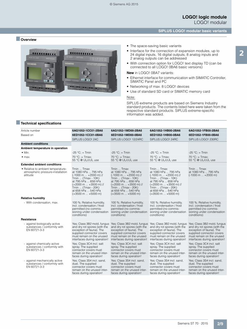
• The space-saving basic variants• Interface for the connection of expansion modules, up to
24 digital inputs, 16 digital outputs, 8 analog inputs and 2 analog outputs can be addressed
• With connection option for LOGO! text display TD (can be connected to all LOGO! 0BA6 basic versions)
New in LOGO! 0BA7 variants:• Ethernet interface for communication with SIMATIC Controller,
SIMATIC Panel and PC• Networking of max. 8 LOGO! devices• Use of standard SD card or SIMATIC memory card
Note:
SIPLUS extreme products are based on Siemens Industry standard products. The contents listed here were taken from the respective standard products. SIPLUS extreme-specific information was added.
■ Technical specifications
Article number 6AG1052-1CC01-2BA6 6AG1052-1MD00-2BA6 6AG1052-1HB00-2BA6 6AG1052-1FB00-2BA6
Based on 6ED1052-1CC01-0BA6 6ED1052-1MD00-0BA6 6ED1052-1HB00-0BA6 6ED1052-1FB00-0BA6
SIPLUS LOGO! 24C SIPLUS LOGO! 12/24RC SIPLUS LOGO! 24RC SIPLUS LOGO! 230RC
Ambient conditions
Ambient temperature in operation
• Min. -25 °C; = Tmin -25 °C; = Tmin -25 °C; = Tmin -25 °C; = Tmin
• max. 70 °C; = Tmax; 55 °C @ UL/cUL use
70 °C; = Tmax; 55 °C @ UL/cUL use
70 °C; = Tmax; 55 °C @ UL/cUL use
70 °C; = Tmax; 55 °C @ UL/cUL use
Extended ambient conditions
• Relative to ambient temperature-atmospheric pressure-installation altitude
Tmin ... Tmax at 1080 hPa ... 795 hPa (-1000 m ... +2000 m) // Tmin ... (Tmax - 10K) at 795 hPa ... 658 hPa (+2000 m ... +3500 m) // Tmin ... (Tmax - 20K) at 658 hPa ... 540 hPa (+3500 m ... +5000 m)
Tmin ... Tmax at 1080 hPa ... 795 hPa (-1000 m ... +2000 m) // Tmin ... (Tmax - 10K) at 795 hPa ... 658 hPa (+2000 m ... +3500 m) // Tmin ... (Tmax - 20K) at 658 hPa ... 540 hPa (+3500 m ... +5000 m)
Tmin ... Tmax at 1080 hPa ... 795 hPa (-1000 m ... +2000 m) // Tmin ... (Tmax - 10K) at 795 hPa ... 658 hPa (+2000 m ... +3500 m) // Tmin ... (Tmax - 20K) at 658 hPa ... 540 hPa (+3500 m ... +5000 m)
Tmin ... Tmax at 1080 hPa ... 795 hPa (-1000 m ... +2000 m)
Relative humidity
- With condensation, max. 100 %; Relative humidity, incl. condensation / frost permitted (no commis-sioning under condensation conditions)
100 %; Relative humidity, incl. condensation / frost permitted (no commis-sioning under condensation conditions)
100 %; Relative humidity, incl. condensation / frost permitted (no commis-sioning under condensation conditions)
100 %; Relative humidity, incl. condensation / frost permitted (no commis-sioning under condensation conditions)
Resistance
- against biologically active substances / conformity with EN 60721-3-3
Yes; Class 3B2 mold, fungus and dry rot spores (with the exception of fauna). The supplied connector covers must remain on the unused interfaces during operation!
Yes; Class 3B2 mold, fungus and dry rot spores (with the exception of fauna). The supplied connector covers must remain on the unused interfaces during operation!
Yes; Class 3B2 mold, fungus and dry rot spores (with the exception of fauna). The supplied connector covers must remain on the unused interfaces during operation!
Yes; Class 3B2 mold, fungus and dry rot spores (with the exception of fauna). The supplied connector covers must remain on the unused interfaces during operation!
- against chemically active substances / conformity with EN 60721-3-3
Yes; Class 3C4 incl. salt spray. The supplied connector covers must remain on the unused inter-faces during operation!
Yes; Class 3C4 incl. salt spray. The supplied connector covers must remain on the unused inter-faces during operation!
Yes; Class 3C4 incl. salt spray. The supplied connector covers must remain on the unused inter-faces during operation!
Yes; Class 3C4 incl. salt spray. The supplied connector covers must remain on the unused inter-faces during operation!
- against mechanically active substances / conformity with EN 60721-3-3
Yes; Class 3S4 incl. sand, dust. The supplied connector covers must remain on the unused inter-faces during operation!
Yes; Class 3S4 incl. sand, dust. The supplied connector covers must remain on the unused inter-faces during operation!
Yes; Class 3S4 incl. sand, dust. The supplied connector covers must remain on the unused inter-faces during operation!
Yes; Class 3S4 incl. sand, dust. The supplied connector covers must remain on the unused inter-faces during operation!
ST70_Kap02_EN.book Seite 9 Mittwoch, 13. Mai 2015 8:41 08
© Siemens AG 2015

2/10 Siemens ST 70 · 2015
2
■ Technical specifications (continued)
LOGO! logic moduleLOGO! modular
SIPLUS LOGO! modular basic variants
■ Ordering data Article No. Article No.
Article number 6AG1052-1MD00-2BA7 6AG1052-1FB00-2BA7
Based on 6ED1052-1MD00-0BA7 6ED1052-1FB00-0BA7
SIPLUS LOGO!12/24RCE SIPLUS LOGO! 230RCE
Ambient conditions
Ambient temperature in operation
• Min. -25 °C; = Tmin -25 °C; = Tmin
• max. 70 °C; = Tmax 70 °C; = Tmax
Extended ambient conditions
• Relative to ambient temperature-atmospheric pressure-installation altitude
Tmin ... Tmax at 1080 hPa ... 795 hPa (-1000 m ... +2000 m) // Tmin ... (Tmax - 10K) at 795 hPa ... 658 hPa (+2000 m ... +3500 m) // Tmin ... (Tmax - 20K) at 658 hPa ... 540 hPa (+3500 m ... +5000 m)
Tmin ... Tmax at 1080 hPa ... 795 hPa (-1000 m ... +2000 m)
Relative humidity
- With condensation, max. 100 %; Relative humidity, incl. condensation / frost permitted (no commissioning under condensation conditions)
100 %; Relative humidity, incl. condensation / frost permitted (no commissioning under condensation conditions)
Resistance
- against biologically active substances / conformity with EN 60721-3-3
Yes; Class 3B2 mold, fungus and dry rot spores (with the exception of fauna). The supplied connector covers must remain on the unused interfaces during operation!
Yes; Class 3B2 mold, fungus and dry rot spores (with the exception of fauna). The supplied connector covers must remain on the unused interfaces during operation!
- against chemically active substances / conformity with EN 60721-3-3
Yes; Class 3C4 incl. salt spray according to EN 60068-2-52 (degree of severity 3). The supplied connector covers must remain on the unused interfaces during operation!
Yes; Class 3C4 incl. salt spray according to EN 60068-2-52 (degree of severity 3). The supplied connector covers must remain on the unused interfaces during operation!
- against mechanically active substances / conformity with EN 60721-3-3
Yes; Class 3S4 incl. sand, dust. The supplied connector covers must remain on the unused interfaces during operation!
Yes; Class 3S4 incl. sand, dust. The supplied connector covers must remain on the unused interfaces during operation!
SIPLUS LOGO! 24
24 V DC supply voltage, 8 digital inputs 24 V DC, of which 4 can be used in analog mode (0 to 10 V), 4 digital outputs 24 V DC, 0.3 A; integrated time switch; 200 function blocks can be interlinked,modular expansion capability
Extended temperature range and exposure to media
6AG1052-1CC01-2BA6
SIPLUS LOGO! 230RC
115/230 V AC/DC supply voltage, 8 digital inputs 115/230 V AC/DC, 4 relay outputs 10 A, integral time switch; 200 function blocks can be interlinked, modular expansion capability
Extended temperature range and exposure to media
6AG1052-1FB00-2BA6
SIPLUS LOGO! 230RCE
115/230 V AC/DC supply voltage, 8 digital inputs 115/230 V AC/DC, 4 relay outputs 10 A, integral time switch; 400 function blocks can be interlinked, Ethernet interface, modular expansion capability
Extended temperature range and exposure to media
6AG1052-1FB00-2BA7
SIPLUS LOGO! 24RC
24 V AC/DC supply voltage, 8 digital inputs 24 V AC/DC, 4 relay outputs 10 A, integral time switch; 200 function blocks can be interlinked,modular expansion capability
Extended temperature range and exposure to media
6AG1052-1HB00-2BA6
SIPLUS LOGO! 12/24RC
12/24 V DC power supply, 8x 12/24 V DC digital inputs, of which 4 can be used in analog mode (0 to 10 V)4x 10 A relay outputs, integral time switch; 200 function blocks can be interlinked,modular expansion capability
Extended temperature range and exposure to media
6AG1052-1MD00-2BA6
SIPLUS LOGO! 12/24RCE
12/24 V DC supply voltage, 8 digital inputs 12/24 V DC, of which 4 can be used in analog mode (0 to 10 V)4 relay outputs 10 A, integral time switch; 400 function blocks can be interlinked,Ethernet interface,modular expansion capability
Extended temperature range and exposure to media
6AG1052-1MD00-2BA7
Accessories
SIPLUS Upmiter upstream device 6AG1053-1AA00-2AA0
for reliable operation at the battery of combustion engines
Further accessories See LOGO! modular basic variants, page 2/7
ST70_Kap02_EN.book Seite 10 Mittwoch, 13. Mai 2015 8:41 08
© Siemens AG 2015
2/11Siemens ST 70 · 2015
2
LOGO! logic moduleLOGO! modular
LOGO! modular pure variants
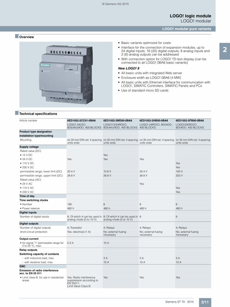
■ Overview
• Basic variants optimized for costs• Interface for the connection of expansion modules, up to
24 digital inputs, 16 (20) digital outputs, 8 analog inputs and 2 (8) analog outputs can be addressed
• With connection option for LOGO! TD text display (can be connected to all LOGO! 0BA6 basic variants)
New LOGO! 8• All basic units with integrated Web server• Enclosure width as LOGO! 0BA6 (4 MW)• All basic units with Ethernet interface for communication with
LOGO!, SIMATIC Controllers, SIMATIC Panels and PCs• Use of standard micro SD cards
■ Technical specifications
Article number 6ED1052-2CC01-0BA8 6ED1052-2MD00-0BA8 6ED1052-2HB00-0BA8 6ED1052-2FB00-0BA8
LOGO! 24CEO, 8DI(4AI)/4DO, 400 BLOCKS
LOGO!12/24RCEO, 8DI(4AI)/4DO, 400 BLOCKS
LOGO! 24RCEO, 8DI/4DO, 400 BLOCKS
LOGO!230RCEO, 8DI/4DO, 400 BLOCKS
Product type designation
Installation type/mounting
Mounting on 35 mm DIN rail, 4 spacing units wide
on 35 mm DIN rail, 4 spacing units wide
on 35 mm DIN rail, 4 spacing units wide
on 35 mm DIN rail, 4 spacing units wide
Supply voltage
Rated value (DC)
• 12 V DC Yes
• 24 V DC Yes Yes Yes
• 115 V DC Yes
• 230 V DC Yes
permissible range, lower limit (DC) 20.4 V 10.8 V 20.4 V 100 V
permissible range, upper limit (DC) 28.8 V 28.8 V 28.8 V 253 V
Rated value (AC)
• 24 V AC Yes
• 115 V AC Yes
• 230 V AC Yes
Time of day
Time switching clocks
• Number 190 8 8 8
• Power reserve 480 h 480 h 480 h 480 h
Digital inputs
Number of digital inputs 8; Of which 4 can be used in analog mode (0 to 10 V)
8; Of which 4 can be used in analog mode (0 to 10 V)
8 8
Digital outputs
Number of digital outputs 4; Transistor 4; Relays 4; Relays 4; Relays
short-circuit protection Yes; electrical (1 A) No; external fusing necessary
No; external fusing necessary
No; external fusing necessary
Output current
• for signal "1" permissible range for 0 to 55 °C, max.
0.3 A 10 A
Relay outputs
Switching capacity of contacts
- with inductive load, max. 3 A 3 A 3 A
- with resistive load, max. 10 A 10 A 10 A
EMC
Emission of radio interference acc. to EN 55 011
• Limit class B, for use in residential areas
Yes; Radio interference suppression according to EN 55011, Limit Value Class B
Yes Yes Yes
ST70_Kap02_EN.book Seite 11 Mittwoch, 13. Mai 2015 8:41 08
© Siemens AG 2015

2/12 Siemens ST 70 · 2015
2
■ Technical specifications (continued)
LOGO! logic moduleLOGO! modular
LOGO! modular pure variants
Degree and class of protection
Degree of protection to EN 60529
• IP20 Yes Yes Yes Yes
Standards, approvals, certificates
CSA approval Yes Yes Yes Yes
UL approval Yes Yes Yes Yes
FM approval Yes Yes Yes Yes
Developed in accordance with IEC 61131
Yes Yes Yes Yes
according to VDE 0631 Yes Yes Yes Yes
Marine approval
• Marine approval Yes Yes Yes Yes
Ambient conditions
Ambient temperature in operation
• Min. 0 °C 0 °C 0 °C 0 °C
• max. 55 °C 55 °C 55 °C 55 °C
Dimensions
Width 71.5 mm 71.5 mm 71.5 mm 71.5 mm
Height 90 mm 90 mm 90 mm 90 mm
Depth 58 mm 58 mm 58 mm 58 mm
Article number 6ED1052-2CC01-0BA6 6ED1052-2MD00-0BA6 6ED1052-2HB00-0BA6 6ED1052-2FB00-0BA6
LOGO! 24CO, 8DI(4AI)/4DO, 200 BLOCKS
LOGO! 12/24RCO, 8DI(4AI)/4DO, 200 BLOCKS
LOGO! 24RCO, 8DI/4DO, 200 BLOCKS
LOGO! 230RCO, 8DI/4DO, 200 BLOCKS
Product type designation
Installation type/mounting
Mounting on 35 mm DIN rail, 4 spacing units wide
on 35 mm DIN rail, 4 spacing units wide
on 35 mm DIN rail, 4 spacing units wide
on 35 mm DIN rail, 4 spacing units wide
Supply voltage
Rated value (DC)
• 12 V DC Yes
• 24 V DC Yes Yes Yes
• 115 V DC Yes
• 230 V DC Yes
permissible range, lower limit (DC) 20.4 V 10.8 V 20.4 V 100 V
permissible range, upper limit (DC) 28.8 V 28.8 V 28.8 V 253 V
Rated value (AC)
• 24 V AC Yes
• 115 V AC Yes
• 230 V AC Yes
Time of day
Time switching clocks
• Number 190 8 8 8
• Power reserve 80 h 80 h 80 h 80 h
Digital inputs
Number of digital inputs 8; Of which 4 can be used in analog mode (0 to 10 V)
8; Of which 4 can be used in analog mode (0 to 10 V)
8 8
Digital outputs
Number of digital outputs 4; Transistor 4; Relays 4; Relays 4; Relays
short-circuit protection Yes; electrical (1 A) No; external fusing necessary
No; external fusing necessary
No; external fusing necessary
Output current
• for signal "1" permissible range for 0 to 55 °C, max.
0.3 A
Relay outputs
Switching capacity of contacts
- with inductive load, max. 3 A 3 A 3 A
- with resistive load, max. 10 A 10 A 10 A
Article number 6ED1052-2CC01-0BA8 6ED1052-2MD00-0BA8 6ED1052-2HB00-0BA8 6ED1052-2FB00-0BA8
LOGO! 24CEO, 8DI(4AI)/4DO, 400 BLOCKS
LOGO!12/24RCEO, 8DI(4AI)/4DO, 400 BLOCKS
LOGO! 24RCEO, 8DI/4DO, 400 BLOCKS
LOGO!230RCEO, 8DI/4DO, 400 BLOCKS
ST70_Kap02_EN.book Seite 12 Mittwoch, 13. Mai 2015 8:41 08
© Siemens AG 2015

2/13Siemens ST 70 · 2015
2
■ Technical specifications (continued)
LOGO! logic moduleLOGO! modular
LOGO! modular pure variants
■ Ordering data Article No. Article No.
EMC
Emission of radio interference acc. to EN 55 011
• Limit class B, for use in residential areas
Yes; Radio interference suppression according to EN 55011, Limit Value Class B
Yes Yes Yes
Degree and class of protection
Degree of protection to EN 60529
• IP20 Yes Yes Yes Yes
Standards, approvals, certificates
CSA approval Yes Yes Yes Yes
UL approval Yes Yes Yes Yes
FM approval Yes Yes Yes Yes
Developed in acc. with IEC 61131 Yes Yes Yes Yes
according to VDE 0631 Yes Yes Yes Yes
Marine approval
• Marine approval Yes Yes Yes Yes
Ambient conditions
Ambient temperature in operation
• Min. 0 °C 0 °C 0 °C 0 °C
• max. 55 °C 55 °C 55 °C 55 °C
Dimensions
Width 72 mm 72 mm 72 mm 72 mm
Height 90 mm 90 mm 90 mm 90 mm
Depth 55 mm 55 mm 55 mm 55 mm
Article number 6ED1052-2CC01-0BA6 6ED1052-2MD00-0BA6 6ED1052-2HB00-0BA6 6ED1052-2FB00-0BA6
LOGO! 24CO, 8DI(4AI)/4DO, 200 BLOCKS
LOGO! 12/24RCO, 8DI(4AI)/4DO, 200 BLOCKS
LOGO! 24RCO, 8DI/4DO, 200 BLOCKS
LOGO! 230RCO, 8DI/4DO, 200 BLOCKS
LOGO! 8 logic module
LOGO! 24CEo logic module 6ED1052-2CC01-0BA8
24 V DC supply voltage, 8 digital inputs 24 V DC, of which 4 can be used in analog mode (0 to 10 V), 4 digital outputs 24 V DC, 0.3 A, integral time switch Ethernet interface; without display and keyboard; 400 function blocks can be interlinked,modular expansion capability
LOGO! 12/24RCEo logic module 6ED1052-2MD00-0BA8
12...24 V DC supply voltage, 8 digital inputs 12...24 V DC, of which 4 can be used in analog mode (0 to 10 V), 4 relay outputs 10 A, integral time switch; without display and keyboard; 400 function blocks can be interlinked,modular expansion capability
LOGO! 24RCEo logic module 6ED1052-2HB00-0BA8
24 V AC/DC supply voltage, 8 digital inputs 24 V AC/DC, 4 relay outputs 10 A, integral time switch; without display and keyboard; 400 function blocks can be interlinked,modular expansion capability
LOGO! 230RCEo logic module 6ED1052-2FB00-0BA8
115...230 V AC/DC supply voltage, 8 digital inputs 115...230 V AC/DC, 4 relay outputs 10 A, integral time switch; without display and keyboard; 400 function blocks can be interlinked,modular expansion capability
LOGO! 6 logic module
LOGO! 24Co logic module 6ED1052-2CC01-0BA6
24 V DC supply voltage, 8 digital inputs 24 V DC, of which 4 can be used in analog mode (0 to 10 V), 4 digital outputs 24 V DC, 0.3 A, integrated time switch; without display and keyboard; 200 function blocks can be interlinked,modular expansion capability
LOGO! 12/24RCo logic module 6ED1052-2MD00-0BA6
12/24 V DC supply voltage, 8 digital inputs 12/24 V DC, of which 4 can be used in analog mode (0 to 10 V), 4 relay outputs 10 A, integral time switch; without display and keyboard; 200 function blocks can be interlinked,modular expansion capability
LOGO! 24RCo logic module 6ED1052-2HB00-0BA6
24 V AC/DC supply voltage, 8 digital inputs 24 V AC/DC, 4 relay outputs 10 A, integral time switch; without display and keyboard; 200 function blocks can be interlinked,modular expansion capability
LOGO! 230RCo logic module 6ED1052-2FB00-0BA6
115/230 V AC/DC supply voltage, 8 digital inputs 115/230 V AC/DC, 4 relay outputs 10 A, integral time switch; without display and keyboard; 200 function blocks can be inter-linked,modular expansion capability
ST70_Kap02_EN.book Seite 13 Mittwoch, 13. Mai 2015 8:41 08
© Siemens AG 2015

2/14 Siemens ST 70 · 2015
2
■ Ordering data Article No. Article No.
LOGO! logic moduleLOGO! modular
LOGO! modular pure variants
Accessories for LOGO! 8
LOGO! TDE text display 6ED1055-4MH00-0BA1
6-line text display, can be connected to all LOGO! 8 Basic and Pure versions, with 2 Ethernet interfaces; including installation accessories.
Requires additional 12 V DC or 24 V AC/DC power supply
LOGO!Soft Comfort V8 6ED1058-0BA08-0YA1
For programming on the PC in LAD/FBD; executes on Windows 8, 7, XP, Linux and Mac OSX; on DVD
LOGO!Soft Comfort V8 Upgrade 6ED1058-0CA08-0YE1
Upgrade from V1.0 to V8, on DVD
LOGO! 8 Starter Kits
In TANOS Box, with LOGO! 8, LOGO! Soft Comfort V8, WinCC Basic V13, Ethernet cable,
LOGO! 8 12/24 V Starter Kit 6ED1057-3BA00-0AA8
With LOGO! 12/24RCE, LOGO! Power 24 V 1.3 A
LOGO! 8 230V Starter Kit 6ED1057-3BA02-0AA8
With LOGO! 230RCE
LOGO! 8 TDE Starter Kit 6ED1057-3BA10-0AA8
With LOGO! 12/24RCEO, LOGO! Power 24 V, 1.3 A, LOGO! TDE
LOGO! 8 KP300 Basic Starter Kit 6AV2132-0HA00-0AA1
With LOGO! 12/24RCE, LOGO! Power 24 V 1.3 A, KP300 Basic mono PN
LOGO! 8 KTP400 Basic Starter Kit 6AV2132-0KA00-0AA1
With LOGO! 12/24RCE, LOGO! Power 24 V 1.3 A, KTP400 Basic
LOGO! 8 KTP700 Basic Starter Kit 6AV2132-3GB00-0AA1
With LOGO! 12/24RCE, LOGO! Power 24 V 1.3 A, KTP700 Basic
Accessories for LOGO! 6
LOGO! TD text display 6ED1055-4MH00-0BA0
4-line text display, can be connected to all LOGO! 0BA6 Basic and Pure versions, including connecting cable
SIPLUS LOGO! TD text display 6AG1055-4MH00-2BA0
(Extended temperature range -10 ... +60 °C and medial loading)
4-line text display, can be connected to all LOGO! 0BA6 Basic and Pure versions, including connecting cable
LOGO! Memory Card 6ED1056-1DA00-0BA0
Program module for copying, with know-how protection
LOGO battery card 6ED1056-6XA00-0BA0
Battery module for backing up the integral real-time clock (not LOGO! 24)
LOGO! memory/battery card 6ED1056-7DA00-0BA0
Combined program and battery module, with know-how protection and buffer for the integral real-time clock (not LOGO! 24o)
LOGO! PROM 6AG1057-1AA01-0BA6
Programming device used to simultaneously reproduce program module contents on up to 8 program modules
LOGO!Soft Comfort V8 6ED1058-0BA08-0YA1
For programming on the PC in LAD/FBD; executes on Windows 8, 7, XP, Linux and Mac OSX; on DVD
LOGO!Soft Comfort V8 Upgrade 6ED1058-0CA08-0YE1
Upgrade from V1.0 to V8, on DVD
LOGO! PC cable 6ED1057-1AA00-0BA0
For program transfer between LOGO! and the PC
LOGO! USB PC cable 6ED1057-1AA01-0BA0
For transferring the program between LOGO! and PC, including driver on CD-ROM
LOGO! modem cable 6ED1057-1CA00-0BA0
Adapter cable for analog modem communication
ST70_Kap02_EN.book Seite 14 Mittwoch, 13. Mai 2015 8:41 08
© Siemens AG 2015

2/15Siemens ST 70 · 2015
2
LOGO! logic moduleLOGO! modular
SIPLUS LOGO! modular pure variants
■ Overview
• Basic variants optimized for costs• Interface for the connection of expansion modules,
up to 24 digital inputs, 16 digital outputs, 8 analog inputs and 2 analog outputs can be addressed
• With connection option for LOGO! text display TD (can be connected to all LOGO! 0BA6 basic versions)
Note:
SIPLUS extreme products are based on Siemens Industry standard products. The contents listed here were taken from the respective standard products. SIPLUS extreme-specific information was added.
■ Technical specifications
Article number 6AG1052-2CC01-2BA6 6AG1052-2MD00-2BA6 6AG1052-2HB00-2BA6 6AG1052-2FB00-2BA6
Based on 6ED1052-2CC01-0BA6 6ED1052-2MD00-0BA6 6ED1052-2HB00-0BA6 6ED1052-2FB00-0BA6
SIPLUS LOGO! 24CO SIPLUS LOGO! 12/24RCO SIPLUS LOGO! 24RCO SIPLUS LOGO! 230RCO
Ambient conditions
Ambient temperature in operation
• Min. -40 °C; = Tmin -40 °C; = Tmin -40 °C; = Tmin -40 °C; = Tmin
• max. 70 °C; = Tmax; 55 °C @ UL/cUL use
70 °C; = Tmax; 55 °C @ UL/cUL use
70 °C; = Tmax; 55 °C @ UL/cUL use
70 °C; = Tmax; 55 °C @ UL/cUL use
Extended ambient conditions
• Relative to ambient temperature-atmospheric pressure-installation altitude
Tmin ... Tmax at 1080 hPa ... 795 hPa (-1000 m ... +2000 m) // Tmin ... (Tmax - 10K) at 795 hPa ... 658 hPa (+2000 m ... +3500 m) // Tmin ... (Tmax - 20K) at 658 hPa ... 540 hPa (+3500 m ... +5000 m)
Tmin ... Tmax at 1080 hPa ... 795 hPa (-1000 m ... +2000 m) // Tmin ... (Tmax - 10K) at 795 hPa ... 658 hPa (+2000 m ... +3500 m) // Tmin ... (Tmax - 20K) at 658 hPa ... 540 hPa (+3500 m ... +5000 m)
Tmin ... Tmax at 1080 hPa ... 795 hPa (-1000 m ... +2000 m) // Tmin ... (Tmax - 10K) at 795 hPa ... 658 hPa (+2000 m ... +3500 m) // Tmin ... (Tmax - 20K) at 658 hPa ... 540 hPa (+3500 m ... +5000 m)
Tmin ... Tmax at 1080 hPa ... 795 hPa (-1000 m ... +2000 m)
Relative humidity
- With condensation, max. 100 %; Relative humidity, incl. condensation / frost permitted (no commis-sioning under condensation conditions)
100 %; Relative humidity, incl. condensation / frost permitted (no commis-sioning under condensation conditions)
100 %; Relative humidity, incl. condensation / frost permitted (no commis-sioning under condensation conditions)
100 %; Relative humidity, incl. condensation / frost permitted (no commis-sioning under condensation conditions)
Resistance
- against biologically active substances / conformity with EN 60721-3-3
Yes; Class 3B2 mold, fungus and dry rot spores (with the exception of fauna). The supplied connector covers must remain on the unused interfaces during operation!
Yes; Class 3B2 mold, fungus and dry rot spores (with the exception of fauna). The supplied connector covers must remain on the unused interfaces during operation!
Yes; Class 3B2 mold, fungus and dry rot spores (with the exception of fauna). The supplied connector covers must remain on the unused interfaces during operation!
Yes; Class 3B2 mold, fungus and dry rot spores (with the exception of fauna). The supplied connector covers must remain on the unused interfaces during operation!
- against chemically active substances / conformity with EN 60721-3-3
Yes; Class 3C4 incl. salt spray. The supplied connector covers must remain on the unused inter-faces during operation!
Yes; Class 3C4 incl. salt spray. The supplied connector covers must remain on the unused inter-faces during operation!
Yes; Class 3C4 incl. salt spray. The supplied connector covers must remain on the unused inter-faces during operation!
Yes; Class 3C4 incl. salt spray. The supplied connector covers must remain on the unused inter-faces during operation!
- against mechanically active substances / conformity with EN 60721-3-3
Yes; Class 3S4 incl. sand, dust. The supplied connector covers must remain on the unused inter-faces during operation!
Yes; Class 3S4 incl. sand, dust. The supplied connector covers must remain on the unused inter-faces during operation!
Yes; Class 3S4 incl. sand, dust. The supplied connector covers must remain on the unused inter-faces during operation!
Yes; Class 3S4 incl. sand, dust. The supplied connector covers must remain on the unused inter-faces during operation!
ST70_Kap02_EN.book Seite 15 Mittwoch, 13. Mai 2015 8:41 08
© Siemens AG 2015

2/16 Siemens ST 70 · 2015
2
LOGO! logic moduleLOGO! modular
SIPLUS LOGO! modular pure variants
■ Ordering data Article No. Article No.
SIPLUS LOGO! 24o
24 V DC supply voltage, 8 digital inputs 24 V DC, of which 4 can be used in analog mode (0 to 10 V), 4 digital outputs 24 V DC, 0.3 A, integrated time switch; without display and keyboard; 200 function blocks can be interlinked,modular expansion capability
Extended temperature range and exposure to media
6AG1052-2CC01-2BA6
SIPLUS LOGO! 230RCo
115/230 V AC/DC supply voltage, 8 digital inputs 115/230 V AC/DC, 4 relay outputs 10 A, integral time switch; without display and keyboard; 200 function blocks can be interlinked,modular expansion capability
Extended temperature range and exposure to media
6AG1052-2FB00-2BA6
SIPLUS LOGO! 24RCo
24 V AC/DC supply voltage, 8 digital inputs 24 V AC/DC, 4 relay outputs 10 A, integral time switch; without display and keyboard; 200 function blocks can be interlinked,modular expansion capability
Extended temperature range and exposure to media
6AG1052-2HB00-2BA6
SIPLUS LOGO! 12/24RCo
12/24 V DC supply voltage, 8 digital inputs 12/24 V DC, of which 4 can be used in analog mode (0 to 10 V), 4 relay outputs 10 A, integral time switch; without display and keyboard; 200 function blocks can be interlinked,modular expansion capability
Extended temperature range and exposure to media
6AG1052-2MD00-2BA6
Accessories
SIPLUS Upmiter upstream device 6AG1053-1AA00-2AA0
for reliable operation at the battery of combustion engines
Further accessories See LOGO! modular pure variants, page 2/14
ST70_Kap02_EN.book Seite 16 Mittwoch, 13. Mai 2015 8:41 08
© Siemens AG 2015

2/17Siemens ST 70 · 2015
2
LOGO! logic moduleLOGO! modular
LOGO! modular expansion modules
■ Overview
• Expansion modules for connection to LOGO! modular• With digital inputs and outputs, analog inputs, or analog
outputs
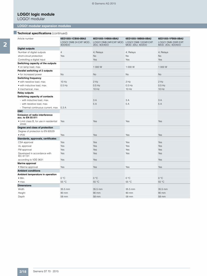
■ Technical specifications
Article number 6ED1055-1CB00-0BA2 6ED1055-1HB00-0BA2 6ED1055-1MB00-0BA2 6ED1055-1FB00-0BA2
LOGO! DM8 24 EXP. MOD., 4DI/4DO
LOGO! DM8 24R EXP. MOD. 2DU, 4DI/4DO
LOGO! DM8 12/24R EXP. MOD. 2DU, 4DI/DO
LOGO! DM8 230R EXP. MOD. 2DU, 4DI/4DO
Product type designation
Installation type/mounting
Mounting on 35 mm DIN rail, 2 spacing units wide
on 35 mm DIN rail, 2 spacing units wide
on 35 mm DIN rail, 2 spacing units wide
on 35 mm DIN rail, 2 spacing units wide
Supply voltage
Rated value (DC)
• 12 V DC Yes
• 24 V DC Yes Yes Yes
• 115 V DC Yes
• 230 V DC Yes
permissible range, lower limit (DC) 20.4 V 20.4 V 10.8 V 100 V
permissible range, upper limit (DC) 28.8 V 28.8 V 28.8 V 253 V
Rated value (AC)
• 24 V AC Yes
• 115 V AC Yes
• 230 V AC Yes
Line frequency
• permissible frequency range, upper limit
63 Hz 63 Hz
Digital inputs
Number of digital inputs 4 4 4 4
Input voltage
• Type of input voltage DC AC/DC DC AC/DC
• for signal "0" < 5V DC < 5 V AC/DC < 5V DC < 40 V AC; < 30 V DC
• for signal "1" > 12V DC > 12 V AC/DC > 8.5 V > 79 V AC, > 79 V DC
Input current
• for signal "0", max. (permissible quiescent current)
0.88 mA 1.1 mA 0.88 mA 0.06 mA; 0.05 mA with AC, 0.06 mA with DC
• for signal "1", typ. 4 mA 5.5 mA 4.2 mA 0.37 mA
Input delay (for rated value of input voltage)
for standard inputs
- at "0" to "1", max. 1.5 ms 1.5 ms 1.5 ms 40 ms
- at "1" to "0", max. 1.5 ms 15 ms 1.5 ms 75 ms
ST70_Kap02_EN.book Seite 17 Mittwoch, 13. Mai 2015 8:41 08
© Siemens AG 2015
2/18 Siemens ST 70 · 2015
2
■ Technical specifications (continued)
LOGO! logic moduleLOGO! modular
LOGO! modular expansion modules
Digital outputs
Number of digital outputs 4 4; Relays 4; Relays 4; Relays
short-circuit protection Yes No No No
Controlling a digital input Yes Yes Yes
Switching capacity of the outputs
• on lamp load, max. 1 000 W 1 000 W 1 000 W
Parallel switching of 2 outputs
• for increased power No No No No
Switching frequency
• with resistive load, max. 10 Hz 2 Hz 2 Hz 2 Hz
• with inductive load, max. 0.5 Hz 0.5 Hz 0.5 Hz 0.5 Hz
• mechanical, max. 10 Hz 10 Hz 10 Hz
Relay outputs
Switching capacity of contacts
- with inductive load, max. 3 A 3 A 3 A
- with resistive load, max. 5 A 5 A 5 A
- Thermal continuous current, max. 0.3 A
EMC
Emission of radio interference acc. to EN 55 011
• Limit class B, for use in residential areas
Yes Yes Yes Yes
Degree and class of protection
Degree of protection to EN 60529
• IP20 Yes Yes Yes Yes
Standards, approvals, certificates
CSA approval Yes Yes Yes Yes
UL approval Yes Yes Yes Yes
FM approval Yes Yes Yes Yes
Developed in accordance with IEC 61131
Yes Yes Yes Yes
according to VDE 0631 Yes Yes Yes
Marine approval
• Marine approval Yes Yes Yes Yes
Ambient conditions
Ambient temperature in operation
• Min. 0 °C 0 °C 0 °C 0 °C
• max. 55 °C 55 °C 55 °C 55 °C
Dimensions
Width 35.5 mm 35.5 mm 35.5 mm 35.5 mm
Height 90 mm 90 mm 90 mm 90 mm
Depth 58 mm 58 mm 58 mm 58 mm
Article number 6ED1055-1CB00-0BA2 6ED1055-1HB00-0BA2 6ED1055-1MB00-0BA2 6ED1055-1FB00-0BA2
LOGO! DM8 24 EXP. MOD., 4DI/4DO
LOGO! DM8 24R EXP. MOD. 2DU, 4DI/4DO
LOGO! DM8 12/24R EXP. MOD. 2DU, 4DI/DO
LOGO! DM8 230R EXP. MOD. 2DU, 4DI/4DO
ST70_Kap02_EN.book Seite 18 Mittwoch, 13. Mai 2015 8:41 08
© Siemens AG 2015

2/19Siemens ST 70 · 2015
2
■ Technical specifications (continued)
LOGO! logic moduleLOGO! modular
LOGO! modular expansion modules
Article number 6ED1055-1CB10-0BA2 6ED1055-1NB10-0BA2 6ED1055-1FB10-0BA2
LOGO! DM16 24 EXP. MOD., 4DU, 8DI/8DO
LOGO! DM16 24R EXP. MOD. 4DU, 8DI/8DO
LOGO! DM16 230R EXP. MOD. 4DU, 8DI/8DO
Product type designation
Installation type/mounting
Mounting on 35 mm DIN rail, 4 spacing units wide
on 35 mm DIN rail, 4 spacing units wide
on 35 mm DIN rail, 4 spacing units wide
Supply voltage
Rated value (DC)
• 24 V DC Yes Yes
• 115 V DC Yes
• 230 V DC Yes
permissible range, lower limit (DC) 20.4 V 20.4 V 100 V
permissible range, upper limit (DC) 28.8 V 28.8 V 253 V
Rated value (AC)
• 115 V AC Yes
• 230 V AC Yes
Line frequency
• permissible frequency range, upper limit
63 Hz
Digital inputs
Number of digital inputs 8 8 8
Input voltage
• Type of input voltage DC DC AC/DC
• for signal "0" < 5V DC < 5V DC < 40 V AC; < 30 V DC
• for signal "1" > 12V DC > 12V DC > 79 V AC, > 79 V DC
Input current
• for signal "0", max. (permissible quiescent current)
0.85 mA 0.85 mA 0.06 mA; 0.05 mA with AC, 0.06 mA with DC
• for signal "1", typ. 3.5 mA 3.5 mA 0.37 mA
Input delay (for rated value of input voltage)
for standard inputs
- at "0" to "1", max. 1.5 ms 1.5 ms 40 ms
- at "1" to "0", max. 1.5 ms 1.5 ms 75 ms
Digital outputs
Number of digital outputs 8 8; Relays 8
short-circuit protection Yes No No
Controlling a digital input Yes Yes Yes
Switching capacity of the outputs
• on lamp load, max. 1 000 W 1 000 W
Parallel switching of 2 outputs
• for increased power No No No
Switching frequency
• with resistive load, max. 10 Hz 2 Hz 2 Hz
• with inductive load, max. 0.5 Hz 0.5 Hz 0.5 Hz
• mechanical, max. 10 Hz 10 Hz
Relay outputs
Switching capacity of contacts
- with inductive load, max. 3 A 3 A
- with resistive load, max. 5 A 5 A
EMC
Emission of radio interference acc. to EN 55 011
• Limit class B, for use in residential areas
Yes Yes Yes
Degree and class of protection
Degree of protection to EN 60529
• IP20 Yes Yes Yes
ST70_Kap02_EN.book Seite 19 Mittwoch, 13. Mai 2015 8:41 08
© Siemens AG 2015

2/20 Siemens ST 70 · 2015
2
■ Technical specifications (continued)
LOGO! logic moduleLOGO! modular
LOGO! modular expansion modules
Standards, approvals, certificates
CSA approval Yes Yes Yes
UL approval Yes Yes Yes
FM approval Yes Yes Yes
Developed in accordance with IEC 61131
Yes Yes Yes
according to VDE 0631 Yes Yes Yes
Marine approval
• Marine approval Yes Yes Yes
Ambient conditions
Ambient temperature in operation
• Min. 0 °C 0 °C 0 °C
• max. 55 °C 55 °C 55 °C
Dimensions
Width 71.5 mm 71.5 mm 71.5 mm
Height 90 mm 90 mm 90 mm
Depth 58 mm 58 mm 58 mm
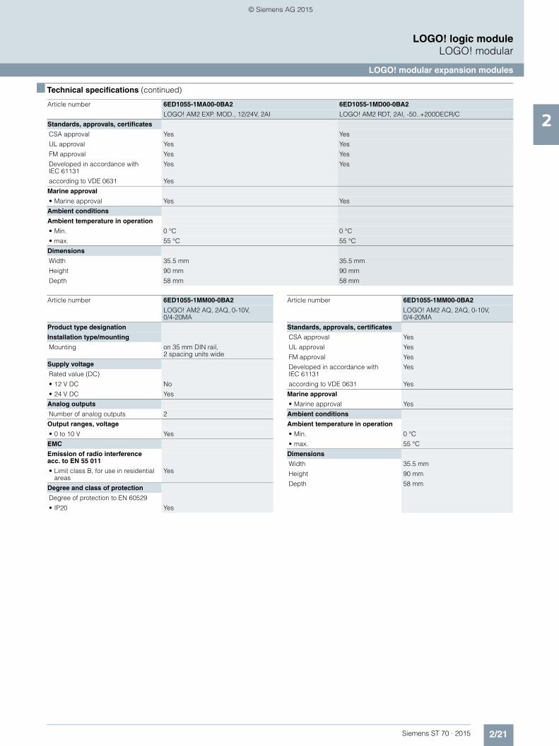
Article number 6ED1055-1MA00-0BA2 6ED1055-1MD00-0BA2
LOGO! AM2 EXP. MOD., 12/24V, 2AI LOGO! AM2 RDT, 2AI, -50..+200DECR/C
Product type designation
Installation type/mounting
Mounting on 35 mm DIN rail, 2 spacing units wide on 35 mm DIN rail, 2 spacing units wide
Supply voltage
Rated value (DC)
• 12 V DC Yes; 10.8V DC to 28.8V DC Yes; 10.8V DC to 28.8V DC
• 24 V DC Yes; 10.8V DC to 28.8V DC Yes; 10.8V DC to 28.8V DC
Analog inputs
Number of analog inputs 2 2; 2 or 3 wire connection
Input ranges
• Voltage Yes No
• Current Yes No
• Resistance thermometer No Yes; For PT100/PT1000 sensors
Input ranges (rated values), voltages
• 0 to +10 V Yes No
Input ranges (rated values), currents
• 0 to 20 mA Yes No
Input ranges (rated values), resistance thermometer
• Pt 100 No Yes
EMC
Emission of radio interference acc. to EN 55 011
• Limit class B, for use in residential areas
Yes Yes
Degree and class of protection
Degree of protection to EN 60529
• IP20 Yes Yes
Article number 6ED1055-1CB10-0BA2 6ED1055-1NB10-0BA2 6ED1055-1FB10-0BA2
LOGO! DM16 24 EXP. MOD., 4DU, 8DI/8DO
LOGO! DM16 24R EXP. MOD. 4DU, 8DI/8DO
LOGO! DM16 230R EXP. MOD. 4DU, 8DI/8DO
ST70_Kap02_EN.book Seite 20 Mittwoch, 13. Mai 2015 8:41 08
© Siemens AG 2015
2/21Siemens ST 70 · 2015
2
■ Technical specifications (continued)
LOGO! logic moduleLOGO! modular
LOGO! modular expansion modules
Standards, approvals, certificates
CSA approval Yes Yes
UL approval Yes Yes
FM approval Yes Yes
Developed in accordance with IEC 61131
Yes Yes
according to VDE 0631 Yes
Marine approval
• Marine approval Yes Yes
Ambient conditions
Ambient temperature in operation
• Min. 0 °C 0 °C
• max. 55 °C 55 °C
Dimensions
Width 35.5 mm 35.5 mm
Height 90 mm 90 mm
Depth 58 mm 58 mm
Article number 6ED1055-1MA00-0BA2 6ED1055-1MD00-0BA2
LOGO! AM2 EXP. MOD., 12/24V, 2AI LOGO! AM2 RDT, 2AI, -50..+200DECR/C
Article number 6ED1055-1MM00-0BA2
LOGO! AM2 AQ, 2AQ, 0-10V, 0/4-20MA
Product type designation
Installation type/mounting
Mounting on 35 mm DIN rail, 2 spacing units wide
Supply voltage
Rated value (DC)
• 12 V DC No
• 24 V DC Yes
Analog outputs
Number of analog outputs 2
Output ranges, voltage
• 0 to 10 V Yes
EMC
Emission of radio interference acc. to EN 55 011
• Limit class B, for use in residential areas
Yes
Degree and class of protection
Degree of protection to EN 60529
• IP20 Yes
Standards, approvals, certificates
CSA approval Yes
UL approval Yes
FM approval Yes
Developed in accordance with IEC 61131
Yes
according to VDE 0631 Yes
Marine approval
• Marine approval Yes
Ambient conditions
Ambient temperature in operation
• Min. 0 °C
• max. 55 °C
Dimensions
Width 35.5 mm
Height 90 mm
Depth 58 mm
Article number 6ED1055-1MM00-0BA2
LOGO! AM2 AQ, 2AQ, 0-10V, 0/4-20MA
ST70_Kap02_EN.book Seite 21 Mittwoch, 13. Mai 2015 8:41 08
© Siemens AG 2015

2/22 Siemens ST 70 · 2015
2
■ Technical specifications (continued)
LOGO! logic moduleLOGO! modular
LOGO! modular expansion modules
Article number 6ED1055-1CB00-0BA0 6ED1055-1HB00-0BA0 6ED1055-1MB00-0BA1 6ED1055-1FB00-0BA1
LOGO! DM8 24 EXP. MOD., 4DI/4DO
LOGO! DM8 24R EXP. MOD. 2DU, 4DI/4DO
LOGO! DM8 12/24R EXP. MOD. 2DU, 4DI/DO
LOGO! DM8 230R EXP. MOD. 2DU, 4DI/4DO
Product type designation
Installation type/mounting
Mounting on 35 mm DIN rail, 2 spacing units wide
on 35 mm DIN rail, 2 spacing units wide
on 35 mm DIN rail, 2 spacing units wide
on 35 mm DIN rail, 2 spacing units wide
Supply voltage
Rated value (DC)
• 12 V DC Yes
• 24 V DC Yes Yes Yes
• 115 V DC Yes
• 230 V DC Yes
permissible range, lower limit (DC) 20.4 V 20.4 V 10.8 V 100 V
permissible range, upper limit (DC) 28.8 V 28.8 V 28.8 V 253 V
Rated value (AC)
• 24 V AC Yes
• 115 V AC Yes
• 230 V AC Yes
Digital inputs
Number of digital inputs 4 4 4 4
Input voltage
• Type of input voltage DC AC/DC DC AC/DC
Digital outputs
Number of digital outputs 4 4; Relays 4; Relays 4; Relays
short-circuit protection Yes No No No
Relay outputs
Switching capacity of contacts
- with inductive load, max. 3 A 3 A 3 A
- with resistive load, max. 5 A 5 A 5 A
- Thermal continuous current, max. 0.3 A
EMC
Emission of radio interference acc. to EN 55 011
• Limit class B, for use in residential areas
Yes Yes Yes Yes
Degree and class of protection
Degree of protection to EN 60529
• IP20 Yes Yes Yes Yes
Standards, approvals, certificates
CSA approval Yes Yes Yes Yes
UL approval Yes Yes Yes Yes
FM approval Yes Yes Yes Yes
Developed in accordance with IEC 61131
Yes Yes Yes Yes
according to VDE 0631 Yes Yes Yes Yes
Marine approval
• Marine approval Yes Yes Yes Yes
Ambient conditions
Ambient temperature in operation
• Min. 0 °C 0 °C 0 °C 0 °C
• max. 55 °C 55 °C 55 °C 55 °C
Dimensions
Width 36 mm; 2 DU 36 mm; 2 DU 36 mm; 2 DU 36 mm; 2 DU
Height 90 mm 90 mm 90 mm 90 mm
Depth 55 mm 55 mm 55 mm 55 mm
ST70_Kap02_EN.book Seite 22 Mittwoch, 13. Mai 2015 8:41 08
© Siemens AG 2015
2/23Siemens ST 70 · 2015
2
■ Technical specifications (continued)
LOGO! logic moduleLOGO! modular
LOGO! modular expansion modules
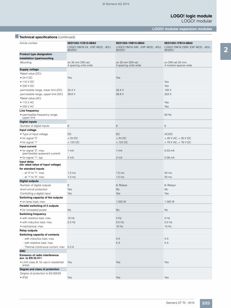
Article number 6ED1055-1CB10-0BA0 6ED1055-1NB10-0BA0 6ED1055-1FB10-0BA0
LOGO! DM16 24, EXP. MOD., 4DU, 8DI/DO
LOGO! DM16 24R, EXP. MOD., 4DU, 8DI/DO
LOGO! DM16 230R, EXP. MOD., 4DU, 8DI/DO
Product type designation
Installation type/mounting
Mounting on 35 mm DIN rail, 4 spacing units wide
on 35 mm DIN rail, 4 spacing units wide
on DIN rail 25 mm, 4 module spaces wide
Supply voltage
Rated value (DC)
• 24 V DC Yes Yes
• 115 V DC Yes
• 230 V DC Yes
permissible range, lower limit (DC) 20.4 V 20.4 V 100 V
permissible range, upper limit (DC) 28.8 V 28.8 V 253 V
Rated value (AC)
• 115 V AC Yes
• 230 V AC Yes
Line frequency
• permissible frequency range, upper limit
63 Hz
Digital inputs
Number of digital inputs 8 8 8
Input voltage
• Type of input voltage DC DC AC/DC
• for signal "0" < 5V DC < 5V DC < 40 V AC; < 30 V DC
• for signal "1" > 12V DC > 12V DC > 79 V AC, > 79 V DC
Input current
• for signal "0", max. (permissible quiescent current)
1 mA 1 mA 0.03 mA
• for signal "1", typ. 2 mA 2 mA 0.08 mA
Input delay (for rated value of input voltage)
for standard inputs
- at "0" to "1", max. 1.5 ms 1.5 ms 50 ms
- at "1" to "0", max. 1.5 ms 1.5 ms 50 ms
Digital outputs
Number of digital outputs 8 8; Relays 8; Relays
short-circuit protection Yes No No
Controlling a digital input Yes Yes Yes
Switching capacity of the outputs
• on lamp load, max. 1 000 W 1 000 W
Parallel switching of 2 outputs
• for increased power No No No
Switching frequency
• with resistive load, max. 10 Hz 2 Hz 2 Hz
• with inductive load, max. 0.5 Hz 0.5 Hz 0.5 Hz
• mechanical, max. 10 Hz 10 Hz
Relay outputs
Switching capacity of contacts
- with inductive load, max. 3 A 3 A
- with resistive load, max. 5 A 5 A
- Thermal continuous current, max. 0.3 A
EMC
Emission of radio interference acc. to EN 55 011
• Limit class B, for use in residential areas
Yes Yes Yes
Degree and class of protection
Degree of protection to EN 60529
• IP20 Yes Yes Yes
ST70_Kap02_EN.book Seite 23 Mittwoch, 13. Mai 2015 8:41 08
© Siemens AG 2015

2/24 Siemens ST 70 · 2015
2
■ Technical specifications (continued)
LOGO! logic moduleLOGO! modular
LOGO! modular expansion modules
Standards, approvals, certificates
CSA approval Yes Yes Yes
UL approval Yes Yes Yes
FM approval Yes Yes Yes
Developed in accordance with IEC 61131
Yes Yes Yes
according to VDE 0631 Yes Yes Yes
Marine approval
• Marine approval Yes Yes Yes
Ambient conditions
Ambient temperature in operation
• Min. 0 °C 0 °C 0 °C
• max. 55 °C 55 °C 55 °C
Dimensions
Width 72 mm; 4 WU 72 mm; 4 WU 72 mm; 4 WU
Height 90 mm 90 mm 90 mm
Depth 53 mm 53 mm 53 mm
Article number 6ED1055-1MA00-0BA0 6ED1055-1MD00-0BA1
LOGO! AM2 EXP. MOD., 12/24V, 2AI, 0-10V LOGO! AM2 RDT, 2AI, -50..+200DECR/C
Product type designation
Installation type/mounting
Mounting on 35 mm DIN rail, 2 spacing units wide
Supply voltage
Rated value (DC)
• 12 V DC Yes Yes; 10.8V DC to 28.8V DC
• 24 V DC Yes Yes; 10.8V DC to 28.8V DC
Analog inputs
Number of analog inputs 2 2; 2 or 3 wire connection
Input ranges
• Voltage Yes No
• Current Yes No
• Resistance thermometer No Yes; For PT100/PT1000 sensors
Input ranges (rated values), voltages
• 0 to +10 V Yes
Input ranges (rated values), currents
• 0 to 20 mA Yes
EMC
Emission of radio interference acc. to EN 55 011
• Limit class B, for use in residential areas
Yes Yes; Radio interference suppression according to EN55011, Limit Value Class B
Degree and class of protection
Degree of protection to EN 60529
• IP20 Yes Yes
Article number 6ED1055-1CB10-0BA0 6ED1055-1NB10-0BA0 6ED1055-1FB10-0BA0
LOGO! DM16 24, EXP. MOD., 4DU, 8DI/DO
LOGO! DM16 24R, EXP. MOD., 4DU, 8DI/DO
LOGO! DM16 230R, EXP. MOD., 4DU, 8DI/DO
ST70_Kap02_EN.book Seite 24 Mittwoch, 13. Mai 2015 8:41 08
© Siemens AG 2015

2/25Siemens ST 70 · 2015
2
■ Technical specifications (continued)
LOGO! logic moduleLOGO! modular
LOGO! modular expansion modules
Standards, approvals, certificates
CSA approval Yes Yes; C22.2 Number 142
UL approval Yes Yes; UL 508
FM approval Yes Yes; FM-Standards No. 3611, 3600, 3810 Class I, Division 2, Group A, B, C, D
Developed in accordance with IEC 61131
Yes Yes; EN 61131-2 (IEC 1131-2)
according to VDE 0631 Yes
Marine approval
• Marine approval Yes Yes; ABS, BV, DNV, GL, LRS, Class NK
Ambient conditions
Ambient temperature in operation
• Min. 0 °C 0 °C
• max. 55 °C 55 °C
Dimensions
Width 36 mm 36 mm
Height 90 mm 90 mm
Depth 55 mm 53 mm
Article number 6ED1055-1MA00-0BA0 6ED1055-1MD00-0BA1
LOGO! AM2 EXP. MOD., 12/24V, 2AI, 0-10V LOGO! AM2 RDT, 2AI, -50..+200DECR/C
Article number 6ED1055-1MM00-0BA1
LOGO! AM2 AQ, 2AQ, 0-10V, 0/4-20MA
Product type designation
Installation type/mounting
Mounting on 35 mm DIN rail, 2 spacing units wide
Supply voltage
Rated value (DC)
• 12 V DC No
• 24 V DC Yes
Analog outputs
Number of analog outputs 2
Output ranges, voltage
• 0 to 10 V Yes
EMC
Emission of radio interference acc. to EN 55 011
• Limit class B, for use in residential areas
Yes; Radio interference suppression according to EN 55011, Limit Value Class B
Degree and class of protection
Degree of protection to EN 60529
• IP20 Yes
Standards, approvals, certificates
CSA approval Yes
UL approval Yes
FM approval Yes
Developed in accordance with IEC 61131
Yes
according to VDE 0631 Yes
Marine approval
• Marine approval Yes
Ambient conditions
Ambient temperature in operation
• Min. 0 °C
• max. 55 °C
Dimensions
Width 36 mm
Height 90 mm
Depth 55 mm
Article number 6ED1055-1MM00-0BA1
LOGO! AM2 AQ, 2AQ, 0-10V, 0/4-20MA
ST70_Kap02_EN.book Seite 25 Mittwoch, 13. Mai 2015 8:41 08
© Siemens AG 2015

2/26 Siemens ST 70 · 2015
2
LOGO! logic moduleLOGO! modular
LOGO! modular expansion modules
■ Ordering data Article No. Article No.
LOGO! 8 expansion modules
LOGO! DM8 24 6ED1055-1CB00-0BA2
24 V DC supply voltage, 4 digital inputs 24 V DC, 4 digital outputs 24 V DC, 0.3 A
LOGO! DM16 24 6ED1055-1CB10-0BA2
24 V DC supply voltage, 8 digital inputs 24 V DC, 8 digital outputs 24 V DC, 0.3 A
LOGO! DM8 12/24R 6ED1055-1MB00-0BA2
12...24 V DC supply voltage, 4 digital inputs 12...24 V DC, 4 relay outputs 5 A
LOGO! DM8 24R 6ED1055-1HB00-0BA2
24 V AC/DC supply voltage, 4 digital inputs 24 V AC/DC, 4 relay outputs 5 A
LOGO! DM16 24R 6ED1055-1NB10-0BA2
24 V DC supply voltage, 8 digital inputs 24 V DC, 8 relay outputs 5 A
LOGO! DM8 230R 6ED1055-1FB00-0BA2
115...230 V AC/DC supply voltage, 4 digital inputs 115...230 V AC/DC, 4 relay outputs 5 A
LOGO! DM16 230R 6ED1055-1FB10-0BA2
115...230 V AC/DC supply voltage, 8 digital inputs 115...230 V AC/DC, 8 relay outputs 5 A
LOGO! AM2 6ED1055-1MA00-0BA2
12...24 V DC supply voltage, 2 analog inputs 0 to 10 V or 0 to 20 mA, resolution 10 bits
LOGO! AM2 PT 100 6ED1055-1MD00-0BA2
12...24 V DC supply voltage, 2 analog inputs Pt100, temperature range -50 °C to 200 °C
LOGO! AM2 AQ 6ED1055-1MM00-0BA2
24 V DC supply voltage, 2 analog outputs 0 to 10 V, 0/4 to 20 mA
LOGO! 6 expansion modules
LOGO! DM8 24 6ED1055-1CB00-0BA0
24 V DC supply voltage, 4 digital inputs 24 V DC, 4 digital outputs 24 V DC, 0.3 A
LOGO! DM16 24 6ED1055-1CB10-0BA0
24 V DC supply voltage, 8 digital inputs 24 V DC, 8 digital outputs 24 V DC, 0.3 A
LOGO! DM8 12/24R 6ED1055-1MB00-0BA1
12/24 V DC supply voltage, 4 digital inputs 12/24 V DC, 4 relay outputs 5 A
LOGO! DM8 24R 6ED1055-1HB00-0BA0
24 V AC/DC supply voltage, 4 digital inputs 24 V AC/DC, 4 relay outputs 5 A
LOGO! DM16 24R 6ED1055-1NB10-0BA0
24 V DC supply voltage, 8 digital inputs 24 V DC, 8 relay outputs 5 A
LOGO! DM8 230R 6ED1055-1FB00-0BA1
115/230 V AC/DC supply voltage, 4 digital inputs 115/230 V AC/DC, 4 relay outputs 5 A
LOGO! DM16 230R 6ED1055-1FB10-0BA0
115/230 V AC/DC supply voltage, 8 digital inputs 115/230 V AC/DC, 8 relay outputs 5 A
LOGO! AM2 6ED1055-1MA00-0BA0
12/24 V DC supply voltage, 2 analog inputs 0 to 10 V or 0 to 20 mA, 10-bit resolution
LOGO! AM2 PT 100 6ED1055-1MD00-0BA1
12/24 V DC supply voltage, 2 analog inputs Pt100, temperature range -50 °C ... 200 °C
LOGO! AM2 AQ 6ED1055-1MM00-0BA1
24 V DC supply voltage, 2 analog outputs 0 to 10 V, 0/4 to 20 mA
Accessories for LOGO! 8
LOGO!Soft Comfort V8 6ED1058-0BA08-0YA1
For programming on the PC in LAD/FBD; executes on Windows 8, 7, XP, Linux and Mac OSX; on DVD
LOGO!Soft Comfort V8 Upgrade 6ED1058-0CA08-0YE1
Upgrade from V1.0 to V8, on DVD
Accessories for LOGO! 6
LOGO! Memory Card 6ED1056-1DA00-0BA0
For copying, with know-how protection
LOGO!Soft Comfort V8 6ED1058-0BA08-0YA1
For programming on the PC in LAD/FBD; executes on Windows 8, 7, XP, Linux and Mac OSX; on DVD
LOGO!Soft Comfort V8 Upgrade 6ED1058-0CA08-0YE1
Upgrade from V1.0 to V8, on DVD
LOGO! PC cable 6ED1057-1AA00-0BA0
For program transfer between LOGO! and the PC
ST70_Kap02_EN.book Seite 26 Mittwoch, 13. Mai 2015 8:41 08
© Siemens AG 2015
2/27Siemens ST 70 · 2015
2
LOGO! logic moduleLOGO! modular
SIPLUS LOGO! modular expansion modules
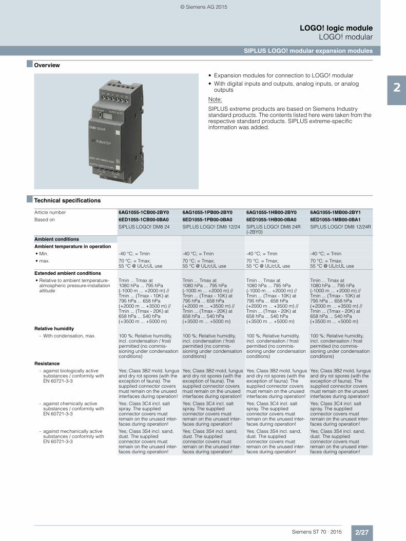
■ Overview
• Expansion modules for connection to LOGO! modular• With digital inputs and outputs, analog inputs, or analog
outputs
Note:
SIPLUS extreme products are based on Siemens Industry standard products. The contents listed here were taken from the respective standard products. SIPLUS extreme-specific information was added.
■ Technical specifications
Article number 6AG1055-1CB00-2BY0 6AG1055-1PB00-2BY0 6AG1055-1HB00-2BY0 6AG1055-1MB00-2BY1
Based on 6ED1055-1CB00-0BA0 6ED1055-1PB00-0BA0 6ED1055-1HB00-0BA0 6ED1055-1MB00-0BA1
SIPLUS LOGO! DM8 24 SIPLUS LOGO! DM8 12/24 SIPLUS LOGO! DM8 24R (-2BY0)
SIPLUS LOGO! DM8 12/24R
Ambient conditions
Ambient temperature in operation
• Min. -40 °C; = Tmin -40 °C; = Tmin -40 °C; = Tmin -40 °C; = Tmin
• max. 70 °C; = Tmax; 55 °C @ UL/cUL use
70 °C; = Tmax; 55 °C @ UL/cUL use
70 °C; = Tmax; 55 °C @ UL/cUL use
70 °C; = Tmax; 55 °C @ UL/cUL use
Extended ambient conditions
• Relative to ambient temperature-atmospheric pressure-installation altitude
Tmin ... Tmax at 1080 hPa ... 795 hPa (-1000 m ... +2000 m) // Tmin ... (Tmax - 10K) at 795 hPa ... 658 hPa (+2000 m ... +3500 m) // Tmin ... (Tmax - 20K) at 658 hPa ... 540 hPa (+3500 m ... +5000 m)
Tmin ... Tmax at 1080 hPa ... 795 hPa (-1000 m ... +2000 m) // Tmin ... (Tmax - 10K) at 795 hPa ... 658 hPa (+2000 m ... +3500 m) // Tmin ... (Tmax - 20K) at 658 hPa ... 540 hPa (+3500 m ... +5000 m)
Tmin ... Tmax at 1080 hPa ... 795 hPa (-1000 m ... +2000 m) // Tmin ... (Tmax - 10K) at 795 hPa ... 658 hPa (+2000 m ... +3500 m) // Tmin ... (Tmax - 20K) at 658 hPa ... 540 hPa (+3500 m ... +5000 m)
Tmin ... Tmax at 1080 hPa ... 795 hPa (-1000 m ... +2000 m) // Tmin ... (Tmax - 10K) at 795 hPa ... 658 hPa (+2000 m ... +3500 m) // Tmin ... (Tmax - 20K) at 658 hPa ... 540 hPa (+3500 m ... +5000 m)
Relative humidity
- With condensation, max. 100 %; Relative humidity, incl. condensation / frost permitted (no commis-sioning under condensation conditions)
100 %; Relative humidity, incl. condensation / frost permitted (no commis-sioning under condensation conditions)
100 %; Relative humidity, incl. condensation / frost permitted (no commis-sioning under condensation conditions)
100 %; Relative humidity, incl. condensation / frost permitted (no commis-sioning under condensation conditions)
Resistance
- against biologically active substances / conformity with EN 60721-3-3
Yes; Class 3B2 mold, fungus and dry rot spores (with the exception of fauna). The supplied connector covers must remain on the unused interfaces during operation!
Yes; Class 3B2 mold, fungus and dry rot spores (with the exception of fauna). The supplied connector covers must remain on the unused interfaces during operation!
Yes; Class 3B2 mold, fungus and dry rot spores (with the exception of fauna). The supplied connector covers must remain on the unused interfaces during operation!
Yes; Class 3B2 mold, fungus and dry rot spores (with the exception of fauna). The supplied connector covers must remain on the unused interfaces during operation!
- against chemically active substances / conformity with EN 60721-3-3
Yes; Class 3C4 incl. salt spray. The supplied connector covers must remain on the unused inter-faces during operation!
Yes; Class 3C4 incl. salt spray. The supplied connector covers must remain on the unused inter-faces during operation!
Yes; Class 3C4 incl. salt spray. The supplied connector covers must remain on the unused inter-faces during operation!
Yes; Class 3C4 incl. salt spray. The supplied connector covers must remain on the unused inter-faces during operation!
- against mechanically active substances / conformity with EN 60721-3-3
Yes; Class 3S4 incl. sand, dust. The supplied connector covers must remain on the unused inter-faces during operation!
Yes; Class 3S4 incl. sand, dust. The supplied connector covers must remain on the unused inter-faces during operation!
Yes; Class 3S4 incl. sand, dust. The supplied connector covers must remain on the unused inter-faces during operation!
Yes; Class 3S4 incl. sand, dust. The supplied connector covers must remain on the unused inter-faces during operation!
ST70_Kap02_EN.book Seite 27 Mittwoch, 13. Mai 2015 8:41 08
© Siemens AG 2015

2/28 Siemens ST 70 · 2015
2
■ Technical specifications (continued)
LOGO! logic moduleLOGO! modular
SIPLUS LOGO! modular expansion modules
Article number 6AG1055-1FB00-2XB1 6AG1055-1FB00-2BY1 6AG1055-1NB10-2BA0
Based on 6ED1055-1FB00-0BA1 6ED1055-1FB00-0BA1 6ED1055-1NB10-0BA0
SIPLUS LOGO! DM8 230R SIPLUS LOGO! DM8 230R SIPLUS LOGO! DM16 24R EXPANSION MODULE
Ambient conditions
Ambient temperature in operation
• Min. -25 °C; = Tmin -40 °C; = Tmin -25 °C; = Tmin
• max. 70 °C; = Tmax; 55 °C @ UL/cUL use 70 °C; = Tmax; 55 °C @ UL/cUL use 70 °C; = Tmax; 55 °C @ UL/cUL use
Extended ambient conditions
• Relative to ambient temperature-atmospheric pressure-installation altitude
Tmin ... Tmax at 1080 hPa ... 795 hPa (-1000 m ... +2000 m)
Tmin ... Tmax at 1080 hPa ... 795 hPa (-1000 m ... +2000 m)
Tmin ... Tmax at 1080 hPa ... 795 hPa (-1000 m ... +2000 m) // Tmin ... (Tmax - 10K) at 795 hPa ... 658 hPa (+2000 m ... +3500 m) // Tmin ... (Tmax - 20K) at 658 hPa ... 540 hPa (+3500 m ... +5000 m)
Relative humidity
- With condensation, max. 100 %; Relative humidity, incl. condensation / frost permitted (no commissioning under condensation conditions)
100 %; Relative humidity, incl. condensation / frost permitted (no commissioning under condensation conditions)
100 %; Relative humidity, incl. condensation / frost permitted (no commissioning under condensation conditions)
Resistance
- against biologically active substances / conformity with EN 60721-3-3
Yes; Class 3B2 mold, fungus and dry rot spores (with the exception of fauna). The supplied connector covers must remain on the unused interfaces during operation!
Yes; Class 3B2 mold, fungus and dry rot spores (with the exception of fauna). The supplied connector covers must remain on the unused interfaces during operation!
Yes; Class 3B2 mold, fungus and dry rot spores (with the exception of fauna). The supplied connector covers must remain on the unused interfaces during operation!
- against chemically active substances / conformity with EN 60721-3-3
Yes; Class 3C4 incl. salt spray. The supplied connector covers must remain on the unused interfaces during operation!
Yes; Class 3C4 incl. salt spray. The supplied connector covers must remain on the unused interfaces during operation!
Yes; Class 3C4 incl. salt spray. The supplied connector covers must remain on the unused interfaces during operation!
- against mechanically active substances / conformity with EN 60721-3-3
Yes; Class 3S4 incl. sand, dust. The supplied connector covers must remain on the unused interfaces during operation!
Yes; Class 3S4 incl. sand, dust. The supplied connector covers must remain on the unused interfaces during operation!
Yes; Class 3S4 incl. sand, dust. The supplied connector covers must remain on the unused interfaces during operation!
ST70_Kap02_EN.book Seite 28 Mittwoch, 13. Mai 2015 8:41 08
© Siemens AG 2015
2/29Siemens ST 70 · 2015
2
■ Technical specifications (continued)
LOGO! logic moduleLOGO! modular
SIPLUS LOGO! modular expansion modules
■ Ordering data Article No. Article No.
Article number 6AG1055-1MA00-2BY0
Based on 6ED1055-1MA00-0BA0
SIPLUS LOGO! AM2
Ambient conditions
Ambient temperature in operation
• Min. -40 °C; = Tmin
• max. 70 °C; = Tmax; 55 °C @ UL/cUL use
Extended ambient conditions
• Relative to ambient temperature-atmospheric pressure-installation altitude
Tmin ... Tmax at 1080 hPa ... 795 hPa (-1000 m ... +2000 m) // Tmin ... (Tmax - 10K) at 795 hPa ... 658 hPa (+2000 m ... +3500 m) // Tmin ... (Tmax - 20K) at 658 hPa ... 540 hPa (+3500 m ... +5000 m)
Relative humidity
- With condensation, max. 100 %; Relative humidity, incl. condensation / frost permitted (no commissioning under condensation conditions)
Resistance
- against biologically active substances / conformity with EN 60721-3-3
Yes; Class 3B2 mold, fungus and dry rot spores (with the exception of fauna). The supplied connector covers must remain on the unused interfaces during operation!
- against chemically active substances / conformity with EN 60721-3-3
Yes; Class 3C4 incl. salt spray. The supplied connector covers must remain on the unused interfaces during operation!
- against mechanically active substances / conformity with EN 60721-3-3
Yes; Class 3S4 incl. sand, dust. The supplied connector covers must remain on the unused interfaces during operation!
Article number 6AG1055-1MM00-2BY1
Based on 6ED1055-1MM00-0BA1
SIPLUS_LOGO!_AM2_AQ
Ambient conditions
Ambient temperature in operation
• Min. -40 °C; = Tmin
• max. 70 °C; = Tmax; 55 °C @ UL/cUL use
Extended ambient conditions
• Relative to ambient temperature-atmospheric pressure-installation altitude
Tmin ... Tmax at 1080 hPa ... 795 hPa (-1000 m ... +2000 m) // Tmin ... (Tmax - 10K) at 795 hPa ... 658 hPa (+2000 m ... +3500 m) // Tmin ... (Tmax - 20K) at 658 hPa ... 540 hPa (+3500 m ... +5000 m)
Relative humidity
- With condensation, max. 100 %; Relative humidity, incl. condensation / frost permitted (no commissioning under condensation conditions)
Resistance
- against biologically active substances / conformity with EN 60721-3-3
Yes; Class 3B2 mold, fungus and dry rot spores (with the exception of fauna). The supplied connector covers must remain on the unused interfaces during operation!
- against chemically active substances / conformity with EN 60721-3-3
Yes; Class 3C4 incl. salt spray. The supplied connector covers must remain on the unused interfaces during operation!
- against mechanically active substances / conformity with EN 60721-3-3
Yes; Class 3S4 incl. sand, dust. The supplied connector covers must remain on the unused interfaces during operation!
SIPLUS LOGO! DM8 24
24 V DC supply voltage, 4 digital inputs 24 V DC, 4 digital outputs 24 V DC, 0.3 A
Extended temperature range and exposure to media
6AG1055-1CB00-2BY0
SIPLUS LOGO! DM8 230R
115/230 V AC/DC supply voltage, 4 digital inputs 115/230 V AC/DC, 4 relay outputs 5 A
Extended temperature range and exposure to media
6AG1055-1FB00-2BY1
SIPLUS LOGO! DM8 24R
24 V AC/DC supply voltage, 4 digital inputs 24 V AC/DC, 4 relay outputs 5 A
Extended temperature range and exposure to media
6AG1055-1HB00-2BY0
SIPLUS LOGO! AM2
12/24 V DC supply voltage, 2 analog inputs 0 ... 10 V or 0 ... 20 mA, 10-bit resolution
Extended temperature range and exposure to media
6AG1055-1MA00-2BY0
SIPLUS LOGO! DM8 12/24R
12/24 V DC supply voltage, 4 digital inputs 12/24 V DC, 4 relay outputs 5 A
Extended temperature range and exposure to media
6AG1055-1MB00-2BY1
SIPLUS LOGO! AM2 AQ
24 V DC supply voltage, 2 analog inputs 0 ... 10 V, 0/4 ... 20 mA, 10-bit resolution
Extended temperature range and exposure to media
6AG1055-1MM00-2BY1
SIPLUS LOGO! DM16 24R
24 V DC supply voltage, 8 digital outputs 24 V DC, 8 relay outputs 5 A
Extended temperature range and exposure to media
6AG1055-1NB10-2BA0
SIPLUS LOGO! DM8 12/24
12/24 V DC supply voltage, 4 digital inputs 12/24 V DC, 4 digital outputs 24 V DC, 0.3 A
Extended temperature range and exposure to media
6AG1055-1PB00-2BY0
Accessories
SIPLUS Upmiter upstream device 6AG1053-1AA00-2AA0
for reliable operation at the battery of combustion engines
Further accessories See LOGO! modular pure variants, page 2/26
ST70_Kap02_EN.book Seite 29 Mittwoch, 13. Mai 2015 8:41 08
© Siemens AG 2015
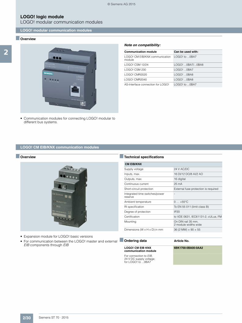
2/30 Siemens ST 70 · 2015
2
LOGO! logic moduleLOGO! modular communication modules
LOGO! modular communication modules
■ Overview
• Communication modules for connecting LOGO! modular to different bus systems.
Note on compatibility:
■ Overview
• Expansion module for LOGO! basic versions• For communication between the LOGO! master and external
EIB components through EIB
■ Technical specifications
■ Ordering data Article No.
Communication module Can be used with:
LOGO! CM EIB/KNX communication module
LOGO! to ...0BA7
LOGO! CSM 12/24 LOGO! ...0BA7/...0BA8
LOGO! CSM 230 LOGO! ...0BA7
LOGO! CMR2020 LOGO! ...0BA8
LOGO! CMR2040 LOGO! ...0BA8
AS-Interface connection for LOGO! LOGO! to ...0BA7
LOGO! CM EIB/KNX communication modules
CM EIB/KNX
Supply voltage 24 V AC/DC
Inputs, max. 16 DI/12 DO/8 AI/2 AO
Outputs, max. 16 digital
Continuous current 25 mA
Short-circuit protection External fuse protection is required
Integrated time switches/power reserve
-
Ambient temperature 0 … +55°C
RI specification To EN 55 011 (limit class B)
Degree of protection IP20
Certification to VDE 0631, IEC61131-2, cULus, FM
Mounting On DIN rail 35 mm, 2 module widths wide
Dimensions (W x H x D) in mm 36 (2 MW) × 90 × 55
LOGO! CM EIB KNX communication module
6BK1700-0BA00-0AA2
For connection to EIB, 24 V DC supply voltage; for LOGO! to ...0BA7
ST70_Kap02_EN.book Seite 30 Mittwoch, 13. Mai 2015 8:41 08
© Siemens AG 2015

2/31Siemens ST 70 · 2015
2
LOGO! logic moduleLOGO! modular communication modules
LOGO! CSM unmanaged
■ Overview
The module is used to connect a LOGO! and up to three other nodes to an Industrial Ethernet network with 10/100 Mbit/s in an electrical linear, tree or star topology.
The essential features of the LOGO! CSM are:• Unmanaged 4-port switch, of which one port is on the front for
easy diagnostics access• Two versions for the voltage ranges 12/24 V DC or
230 V AC/DC• Problem-free connection using four RJ45 standard
connectors• Space-saving, optimized for connection to LOGO!• Low-cost solution for implementing small, local Ethernet
networks• Stand-alone use for networking any Ethernet devices
■ Technical specifications
Article number 6GK7177-1FA10-0AA0 6GK7177-1MA20-0AA0
Product type designation LOGO! CSM 230 LOGO! CSM 12/24
Transmission rate
Transfer rate 10 Mbit/s, 100 Mbit/s 10 Mbit/s, 100 Mbit/s
Interfaces
Number of electrical/optical connections
• for network components or terminal equipment maximum
4 4
Number of electrical connections
• for network components or terminal equipment
4 4
Type of electrical connection
• for network components or terminal equipment
RJ45 port / 1 connection on front of module RJ45 port / 1 connection on front of module
• for power supply 3-pole terminal block 3-pole terminal block
Supply voltage, current consumption, power loss
Type of voltage of the supply voltage AC/DC 115...240 V DC 12/24 V
Supply voltage
• external 230 V 24 V
• external 100 ... 240 V 10.2 ... 30.2 V
Product component fusing at power supply input
Yes Yes
Consumed current maximum 0.02 A 0.15 A
Active power loss
• for DC at 24 V 1.5 W
• with AC at 230 V 1.8 W
Permitted ambient conditions
Ambient temperature
• during operation 0 ... 55 °C 0 ... 55 °C
• during storage -40 ... +70 °C -40 ... +70 °C
• during transport -40 ... +70 °C -40 ... +70 °C
Relative humidity
• at 25 °C without condensation during operation maximum
90 % 90 %
Protection class IP IP20 IP20
ST70_Kap02_EN.book Seite 31 Mittwoch, 13. Mai 2015 8:41 08
© Siemens AG 2015
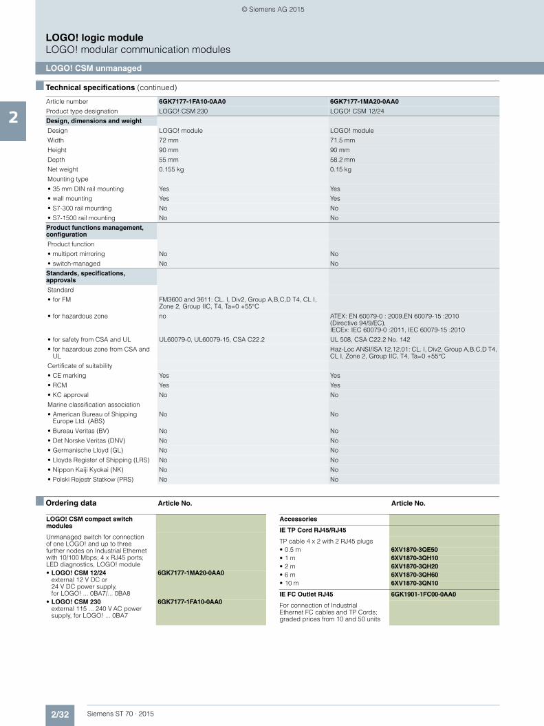
2/32 Siemens ST 70 · 2015
2
■ Technical specifications (continued)
LOGO! logic moduleLOGO! modular communication modules
LOGO! CSM unmanaged
■ Ordering data Article No. Article No.
Design, dimensions and weight
Design LOGO! module LOGO! module
Width 72 mm 71.5 mm
Height 90 mm 90 mm
Depth 55 mm 58.2 mm
Net weight 0.155 kg 0.15 kg
Mounting type
• 35 mm DIN rail mounting Yes Yes
• wall mounting Yes Yes
• S7-300 rail mounting No No
• S7-1500 rail mounting No No
Product functions management, configuration
Product function
• multiport mirroring No No
• switch-managed No No
Standards, specifications, approvals
Standard
• for FM FM3600 and 3611: CL. I, Div2, Group A,B,C,D T4, CL I, Zone 2, Group IIC, T4, Ta=0 +55°C
• for hazardous zone no ATEX: EN 60079-0 : 2009,EN 60079-15 :2010 (Directive 94/9/EC), IECEx: IEC 60079-0 :2011, IEC 60079-15 :2010
• for safety from CSA and UL UL60079-0, UL60079-15, CSA C22.2 UL 508, CSA C22.2 No. 142
• for hazardous zone from CSA and UL
Haz-Loc ANSI/ISA 12.12.01: CL. I, Div2, Group A,B,C,D T4, CL I, Zone 2, Group IIC, T4, Ta=0 +55°C
Certificate of suitability
• CE marking Yes Yes
• RCM Yes Yes
• KC approval No No
Marine classification association
• American Bureau of Shipping Europe Ltd. (ABS)
No No
• Bureau Veritas (BV) No No
• Det Norske Veritas (DNV) No No
• Germanische Lloyd (GL) No No
• Lloyds Register of Shipping (LRS) No No
• Nippon Kaiji Kyokai (NK) No No
• Polski Rejestr Statkow (PRS) No No
Article number 6GK7177-1FA10-0AA0 6GK7177-1MA20-0AA0
Product type designation LOGO! CSM 230 LOGO! CSM 12/24
LOGO! CSM compact switch modules
Unmanaged switch for connection of one LOGO! and up to three further nodes on Industrial Ethernet with 10/100 Mbps; 4 x RJ45 ports; LED diagnostics, LOGO! module• LOGO! CSM 12/24
external 12 V DC or 24 V DC power supply, for LOGO! ... 0BA7/... 0BA8
6GK7177-1MA20-0AA0
• LOGO! CSM 230external 115 ... 240 V AC power supply, for LOGO! ... 0BA7
6GK7177-1FA10-0AA0
Accessories
IE TP Cord RJ45/RJ45
TP cable 4 x 2 with 2 RJ45 plugs• 0.5 m 6XV1870-3QE50• 1 m 6XV1870-3QH10• 2 m 6XV1870-3QH20• 6 m 6XV1870-3QH60• 10 m 6XV1870-3QN10
IE FC Outlet RJ45 6GK1901-1FC00-0AA0
For connection of Industrial Ethernet FC cables and TP Cords; graded prices from 10 and 50 units
ST70_Kap02_EN.book Seite 32 Mittwoch, 13. Mai 2015 8:41 08
© Siemens AG 2015

2/33Siemens ST 70 · 2015
2
LOGO! logic moduleLOGO! modular communication modules
LOGO! CMR (wireless communication)
■ Overview
LOGO! CMR in combination with the LOGO! module is a cost-efficient communication system for monitoring and controlling distributed plants and systems via text message.
LOGO! CMR can send text messages to predefined mobile network numbers and it can also receive text messages from predefined mobile network numbers.
Sending a text message can be initiated by events in the LOGO! basic module as well as by the two digital alarm inputs of the LOGO! CMR. The values in the LOGO! basic module can be directly influenced by receiving a text message.
The two digital outputs can also be switched remotely by incom-ing text messages/emails.
LOGO! CMR determines the current position of the module based on the GPS signal received by the GPS antenna. In addi-tion, LOGO! BM can be time-synchronized by means of the time included in the GPS signal.
Determining the time by means of an NTP server or from the data of the mobile network provider, offers more options for synchro-nization of the LOGO! BM with the current time of day.
Product variant:• LOGO! CMR2020 for use in GSM/GPRS mobile wireless
networks• LOGO! CMR2040 for use in in LTE mobile wireless networks
Warning! The country-specific mobile network approvals must be observed:
DE: www.siemens.de/mobilfunkzulassungen
EN: www.siemens.com/mobilenetwork-approvals
■ Technical specifications
Article number 6GK7142-7BX00-0AX0 6GK7142-7EX00-0AX0
Product type designation LOGO! CMR2020 LOGO! CMR2040
Transmission rate
Transfer rate
• at the 1st interface 10 ... 100 Mbit/s 10 ... 100 Mbit/s
• for GPRS transmission with downlink maximum
80 kbit/s 85.6 kbit/s
• for GPRS transmission with uplink maximum
40 kbit/s 85.6 kbit/s
• for LTE transmission with downlink maximum
100 Mbit/s
• for LTE transmission with uplink maximum
50 Mbit/s
Interfaces
Number of interfaces acc. to Industrial Ethernet
1 1
Number of electrical connections
• at the 1st interface acc. to Industrial Ethernet
1 1
• for external antenna(s) 2 2
• for power supply 1 1
Number of slots
• for SIM cards 1 1
• for memory cards 1 1
Type of electrical connection
• at the 1st interface acc. to Industrial Ethernet
RJ45 port RJ45 port
• for external antenna(s) SMA socket (50 ohms) SMA socket (50 ohms)
• for power supply 3-pole terminal block 3-pole terminal block
Type of antenna
• at port 1 connectable GPS Antenna GPS Antenna
• at port 2 connectable Mobile radio antenna (GPRS/GSM) Mobile radio antenna (GPRS/GSM)
Slot version
• for SIM card Standard Standard
• of the memory card microSD microSD
ST70_Kap02_EN.book Seite 33 Mittwoch, 13. Mai 2015 8:41 08
© Siemens AG 2015

2/34 Siemens ST 70 · 2015
2
■ Technical specifications (continued)
LOGO! logic moduleLOGO! modular communication modules
LOGO! CMR (wireless communication)
Storage capacity of the memory card maximum
8 Gibyte 8 Gibyte
Performance class of the memory card minimum necessary
Class 6 Class 6
Type of file system of the memory card
FAT32 FAT32
Signal-Inputs/outputs
Number of electrical connections for digital input signals
2 2
Type of electrical connection for digital input signals
3 pole terminal block 3 pole terminal block
Digital input version not potential seperated not potential seperated
Input voltage at digital input
• with signal <0> for DC 0 ... 5 V 0 ... 5 V
• for signal <1> for DC 8.5 ... 24 V 8.5 ... 24 V
Input current at digital input for signal <1> maximum
5.5 mA 5.5 mA
Number of electrical connections for digital output signals
2 2
Type of electrical connection for digital output signals
3 pole terminal block 3 pole terminal block
Digital output version transistor, not potential seperated transistor, not potential seperated
Output voltage at digital output
• for signal <1> 12 ... 24 V; value of the actual supply voltage 12 ... 24 V; value of the actual supply voltage
• for signal <0> 0 ... 5 V 0 ... 5 V
Output current at digital output for signal <1> maximum
0.3 A 0.3 A
Wireless technology
Type of mobile wireless service
• is supported SMS, GPRS SMS, GPRS
• Note GPRS (Multislot Class 10, Mobile Station Class B) LTE
Type of mobile network is supported GSM GSM, UMTS, LTE
Operating frequency
• for GSM transmission 850 MHz, 900 MHz, 1800 MHz, 1900 MHz 850 MHz, 900 MHz, 1800 MHz, 1900 MHz
• with UMTS transmission 900 MHz, 2100 MHz
• for LTE transmission 800 MHz, 1800 MHz, 2600 MHz
Supply voltage, current consumption, power loss
Type of voltage of the supply voltage DC DC
Supply voltage external 12 ... 24 V 12 ... 24 V
Supply voltage for GPS antenna maximum
3.8 V; at 5 mA: 3,575 V / at 10 mA: 3,35 V / at 15 mA: 3,125 V
3.8 V; at 5 mA: 3,575 V / at 10 mA: 3,35 V / at 15 mA: 3,125 V
Relative positive tolerance for DC at 24 V
20 % 20 %
Relative negative tolerance for DC at 12 V
10 % 10 %
Consumed current
• from external supply voltage for DC at 12 V maximum
0.25 A 0.25 A
• from external supply voltage for DC at 24 V maximum
0.125 A 0.125 A
Output current for GPS antenna maximum
15 mA 15 mA
Active power loss 3 W 3 W
Article number 6GK7142-7BX00-0AX0 6GK7142-7EX00-0AX0
Product type designation LOGO! CMR2020 LOGO! CMR2040
ST70_Kap02_EN.book Seite 34 Mittwoch, 13. Mai 2015 8:41 08
© Siemens AG 2015

2/35Siemens ST 70 · 2015
2
■ Technical specifications (continued)
LOGO! logic moduleLOGO! modular communication modules
LOGO! CMR (wireless communication)
Permitted ambient conditions
Ambient temperature
• during operation -20 ... +70 °C -20 ... +70 °C
• during storage -40 ... +85 °C -40 ... +85 °C
• during transport -40 ... +85 °C -40 ... +85 °C
Relative humidity at 25 °C without condensation during operation maximum
95 % 95 %
Protection class IP IP20 IP20
Design, dimensions and weight
Module format Compact module, for rail mounting Compact module, for rail mounting
Width 71.5 mm 71.5 mm
Height 90 mm 90 mm
Depth 58.2 mm 58.2 mm
Net weight 0.16 kg 0.16 kg
Mounting type
• 35 mm DIN rail mounting Yes Yes
• wall mounting Yes Yes
Performance data
Number of possible connections to the LOGO! logic module
1 1
Number of users/telephon numbers definable maximum
20 20
Number of user groups definable maximum
20 20
Number of signals for monitoring or device control definable maximum
32 32
Number of events for monitoring definable maximum
32 32
number of actions definable maximum 32 32
Product functions management, configuration
Configuration software
• required WEB-Interface WEB-Interface
Product functions Diagnosis
Product function Web-based diagnostics
Yes Yes
Product functions Security
Product function
• password protection for Web applications
Yes Yes
• switch-off of non-required services Yes Yes
• log file for unauthorized access Yes Yes
Product functions Time
Product function pass on time synchronization
Yes Yes
time synchronization
• from NTP-server Yes Yes
• from GPS-signal Yes Yes
• from mobile network provider Yes Yes
Product functions Position recognition
Product function position detection with GPS
Yes Yes
Article number 6GK7142-7BX00-0AX0 6GK7142-7EX00-0AX0
Product type designation LOGO! CMR2020 LOGO! CMR2040
ST70_Kap02_EN.book Seite 35 Mittwoch, 13. Mai 2015 8:41 08
© Siemens AG 2015
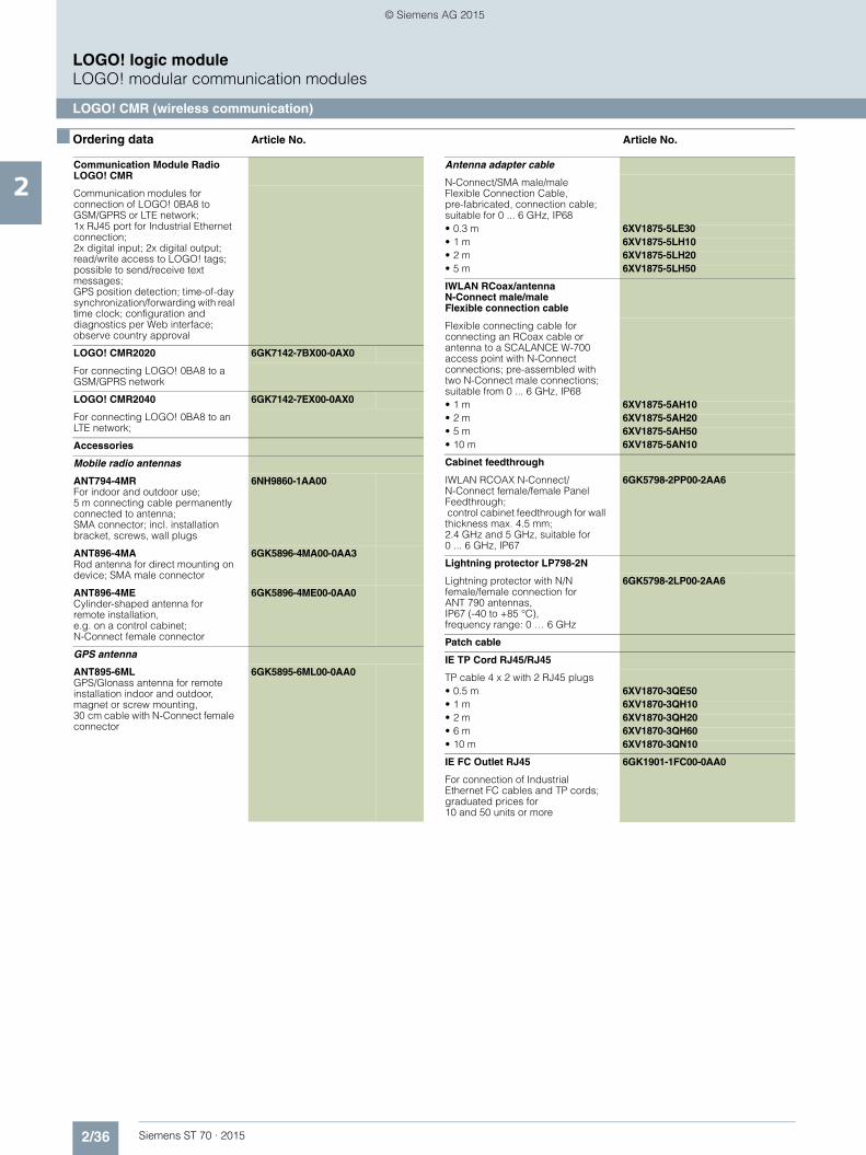
2/36 Siemens ST 70 · 2015
2
LOGO! logic moduleLOGO! modular communication modules
LOGO! CMR (wireless communication)
■ Ordering data Article No. Article No.
Communication Module Radio LOGO! CMR
Communication modules for connection of LOGO! 0BA8 to GSM/GPRS or LTE network; 1x RJ45 port for Industrial Ethernet connection; 2x digital input; 2x digital output; read/write access to LOGO! tags; possible to send/receive text messages; GPS position detection; time-of-day synchronization/forwarding with real time clock; configuration and diagnostics per Web interface; observe country approval
LOGO! CMR2020 6GK7142-7BX00-0AX0
For connecting LOGO! 0BA8 to a GSM/GPRS network
LOGO! CMR2040 6GK7142-7EX00-0AX0
For connecting LOGO! 0BA8 to an LTE network;
Accessories
Mobile radio antennas
ANT794-4MRFor indoor and outdoor use; 5 m connecting cable permanently connected to antenna;SMA connector; incl. installation bracket, screws, wall plugs
6NH9860-1AA00
ANT896-4MARod antenna for direct mounting on device; SMA male connector
6GK5896-4MA00-0AA3
ANT896-4MECylinder-shaped antenna for remote installation, e.g. on a control cabinet; N-Connect female connector
6GK5896-4ME00-0AA0
GPS antenna
ANT895-6MLGPS/Glonass antenna for remote installation indoor and outdoor, magnet or screw mounting,30 cm cable with N-Connect female connector
6GK5895-6ML00-0AA0
Antenna adapter cable
N-Connect/SMA male/male Flexible Connection Cable, pre-fabricated, connection cable; suitable for 0 ... 6 GHz, IP68• 0.3 m 6XV1875-5LE30• 1 m 6XV1875-5LH10• 2 m 6XV1875-5LH20• 5 m 6XV1875-5LH50
IWLAN RCoax/antenna N-Connect male/male Flexible connection cable
Flexible connecting cable for connecting an RCoax cable or antenna to a SCALANCE W-700 access point with N-Connect connections; pre-assembled with two N-Connect male connections; suitable from 0 ... 6 GHz, IP68• 1 m 6XV1875-5AH10• 2 m 6XV1875-5AH20• 5 m 6XV1875-5AH50• 10 m 6XV1875-5AN10
Cabinet feedthrough
IWLAN RCOAX N-Connect/N-Connect female/female Panel Feedthrough; control cabinet feedthrough for wall thickness max. 4.5 mm; 2.4 GHz and 5 GHz, suitable for 0 ... 6 GHz, IP67
6GK5798-2PP00-2AA6
Lightning protector LP798-2N
Lightning protector with N/N female/female connection for ANT 790 antennas, IP67 (-40 to +85 °C), frequency range: 0 … 6 GHz
6GK5798-2LP00-2AA6
Patch cable
IE TP Cord RJ45/RJ45
TP cable 4 x 2 with 2 RJ45 plugs• 0.5 m 6XV1870-3QE50• 1 m 6XV1870-3QH10• 2 m 6XV1870-3QH20• 6 m 6XV1870-3QH60• 10 m 6XV1870-3QN10
IE FC Outlet RJ45 6GK1901-1FC00-0AA0
For connection of Industrial Ethernet FC cables and TP cords; graduated prices for 10 and 50 units or more
ST70_Kap02_EN.book Seite 36 Mittwoch, 13. Mai 2015 8:41 08
© Siemens AG 2015

2/37Siemens ST 70 · 2015
2
LOGO! logic moduleLOGO! modular communication modules
AS-Interface connection for LOGO!
■ Overview
Every LOGO! can now be connected to the AS-Interface system
AS-Interface connection for LOGO!
Using the AS-Interface connection for LOGO!, an intelligent slave can be integrated in the AS-Interface system. With the modular interface it becomes possible to integrate the different basic units in the system according to their functionality. Simi-larly, functionalities can be quickly and easily adapted to new re-quirements by exchanging the basic unit.
The interface module provides four inputs and four outputs on the system. These inputs and outputs do not actually exist in hardware terms, however, but are only virtually present through the interface on the bus.
■ Ordering data Article No.
AS-Interface connection for LOGO!
3RK1400-0CE10-0AA2
ST70_Kap02_EN.book Seite 37 Mittwoch, 13. Mai 2015 8:41 08
© Siemens AG 2015
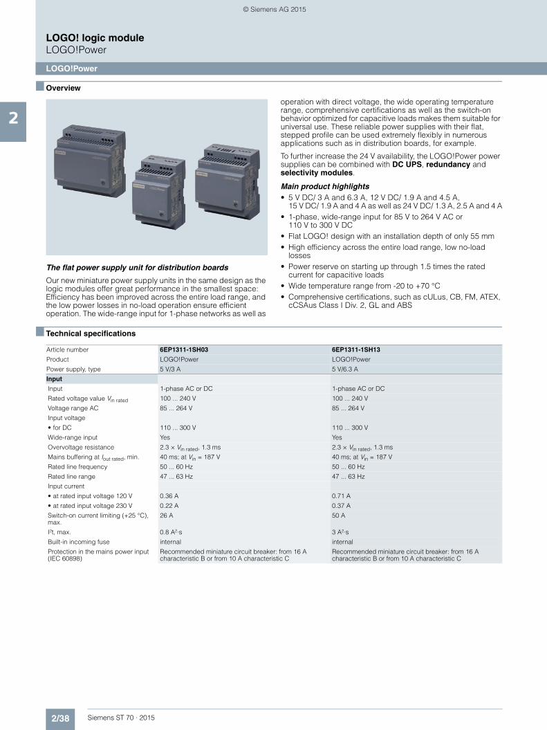
2/38 Siemens ST 70 · 2015
2
LOGO! logic moduleLOGO!Power
LOGO!Power
■ Overview
The flat power supply unit for distribution boards
Our new miniature power supply units in the same design as the logic modules offer great performance in the smallest space: Efficiency has been improved across the entire load range, and the low power losses in no-load operation ensure efficient operation. The wide-range input for 1-phase networks as well as
operation with direct voltage, the wide operating temperature range, comprehensive certifications as well as the switch-on behavior optimized for capacitive loads makes them suitable for universal use. These reliable power supplies with their flat, stepped profile can be used extremely flexibly in numerous applications such as in distribution boards, for example.
To further increase the 24 V availability, the LOGO!Power power supplies can be combined with DC UPS, redundancy and selectivity modules.
Main product highlights• 5 V DC/ 3 A and 6.3 A, 12 V DC/ 1.9 A and 4.5 A,
15 V DC/ 1.9 A and 4 A as well as 24 V DC/ 1.3 A, 2.5 A and 4 A• 1-phase, wide-range input for 85 V to 264 V AC or
110 V to 300 V DC• Flat LOGO! design with an installation depth of only 55 mm• High efficiency across the entire load range, low no-load
losses• Power reserve on starting up through 1.5 times the rated
current for capacitive loads• Wide temperature range from -20 to +70 °C• Comprehensive certifications, such as cULus, CB, FM, ATEX,
cCSAus Class I Div. 2, GL and ABS
■ Technical specifications
Article number 6EP1311-1SH03 6EP1311-1SH13
Product LOGO!Power LOGO!Power
Power supply, type 5 V/3 A 5 V/6.3 A
Input
Input 1-phase AC or DC 1-phase AC or DC
Rated voltage value Vin rated 100 ... 240 V 100 ... 240 V
Voltage range AC 85 ... 264 V 85 ... 264 V
Input voltage
• for DC 110 ... 300 V 110 ... 300 V
Wide-range input Yes Yes
Overvoltage resistance 2.3 × Vin rated, 1.3 ms 2.3 × Vin rated, 1.3 ms
Mains buffering at Iout rated, min. 40 ms; at Vin = 187 V 40 ms; at Vin = 187 V
Rated line frequency 50 ... 60 Hz 50 ... 60 Hz
Rated line range 47 ... 63 Hz 47 ... 63 Hz
Input current
• at rated input voltage 120 V 0.36 A 0.71 A
• at rated input voltage 230 V 0.22 A 0.37 A
Switch-on current limiting (+25 °C), max.
26 A 50 A
I²t, max. 0.8 A²·s 3 A²·s
Built-in incoming fuse internal internal
Protection in the mains power input (IEC 60898)
Recommended miniature circuit breaker: from 16 A characteristic B or from 10 A characteristic C
Recommended miniature circuit breaker: from 16 A characteristic B or from 10 A characteristic C
ST70_Kap02_EN.book Seite 38 Mittwoch, 13. Mai 2015 8:41 08
© Siemens AG 2015

2/39Siemens ST 70 · 2015
2
■ Technical specifications (continued)
LOGO! logic moduleLOGO!Power
LOGO!Power
Output
Output Controlled, isolated DC voltage Controlled, isolated DC voltage
Rated voltage Vout DC 5 V 5 V
Total tolerance, static ± 3 % 3 %
Static mains compensation, approx. 0.2 % 0.1 %
Static load balancing, approx. 1.5 % 2 %
Residual ripple peak-peak, max. 100 mV 100 mV
Residual ripple peak-peak, typ. 10 mV 15 mV
Spikes peak-peak, max. (bandwidth: 20 MHz)
100 mV 100 mV
Spikes peak-peak, typ. (bandwidth: 20 MHz)
20 mV 70 mV
Adjustment range 4.6 ... 5.4 V 4.6 ... 5.4 V
Product function Output voltage adjustable
Yes Yes
Output voltage setting via potentiometer via potentiometer
Status display Green LED for output voltage OK Green LED for output voltage OK
On/off behavior No overshoot of Vout (soft start) No overshoot of Vout (soft start)
Startup delay, max. 0.5 s 0.5 s
Voltage rise, typ. 20 ms 10 ms
Rated current value Iout rated 3 A 6.3 A
Current range 0 ... 3 A 0 ... 6.3 A
• Note +55 ... +70 °C: Derating 2%/K +55 ... +70 °C: Derating 2%/K
Active power supplied typical 15 W 30 W
Parallel switching for enhanced performance
Yes Yes
Numbers of parallel switchable units for enhanced performance
2 2
Efficiency
Efficiency at Vout rated, Iout rated, approx.
77 % 83 %
Power loss at Vout rated, Iout rated, approx.
4 W 6 W
Active power loss during no-load operation maximum
1.5 W 1.5 W
Closed-loop control
Dynamic mains compensation (Vin rated ±15 %), max.
0.2 % 0.2 %
Dynamic load smoothing (Iout: 10/90/10 %), Uout ± typ.
3 % 3 %
Load step setting time 10 to 90%, typ. 2 ms 2 ms
Load step setting time 90 to 10%, typ. 2 ms 2 ms
Protection and monitoring
Output overvoltage protection Yes, according to EN 60950-1 Yes, according to EN 60950-1
Current limitation, typ. 3.8 A 8.2 A
Property of the output Short-circuit proof
Yes Yes
Short-circuit protection Constant current characteristic Constant current characteristic
Enduring short circuit current RMS value
• maximum 5 A 10 A
Overload/short-circuit indicator - -
Article number 6EP1311-1SH03 6EP1311-1SH13
Product LOGO!Power LOGO!Power
Power supply, type 5 V/3 A 5 V/6.3 A
ST70_Kap02_EN.book Seite 39 Mittwoch, 13. Mai 2015 8:41 08
© Siemens AG 2015

2/40 Siemens ST 70 · 2015
2
■ Technical specifications (continued)
LOGO! logic moduleLOGO!Power
LOGO!Power
Safety
Primary/secondary isolation Yes Yes
Galvanic isolation Safety extra-low output voltage Uout acc. to EN 60950-1 and EN 50178
Safety extra-low output voltage Uout acc. to EN 60950-1 and EN 50178
Protection class Class II (without protective conductor) Class II (without protective conductor)
CE mark Yes Yes
UL/CSA approval Yes Yes
UL/cUL (CSA) approval cULus-Listed (UL 508, CSA C22.2 No. 107.1), File E197259; cURus-Recognized (UL 60950, CSA C22.2 No. 60950), File E151273, NEC class 2 (acc. to UL 1310)
cULus-listed (UL 508, CSA C22.2 No. 107.1), File E197259; cURus-recognized (UL 60950, CSA C22.2 No. 60950), File E151273
Explosion protection ATEX (EX) II 3G Ex nA IIC T3; cCSAus (CSA C22.2 No. 213-M1987, ANSI/ISA-12.12.01-2007) Class I, Div. 2, Group ABCD, T4
ATEX (EX) II 3G Ex nA IIC T3; cCSAus (CSA C22.2 No. 213-M1987, ANSI/ISA-12.12.01-2007) Class I, Div. 2, Group ABCD, T4
Certificate of suitability IECEx No No
Certificate of suitability NEC Class 2 Yes No
FM approval Class I, Div. 2, Group ABCD, T4 Class I, Div. 2, Group ABCD, T4
CB approval Yes Yes
Marine approval GL, ABS GL, ABS
Degree of protection (EN 60529) IP20 IP20
EMC
Emitted interference EN 55022 Class B EN 55022 Class B
Supply harmonics limitation not applicable not applicable
Noise immunity EN 61000-6-2 EN 61000-6-2
Operating data
Ambient temperature
• during operation -20 ... +70 °C -20 ... +70 °C
- Note with natural convection with natural convection
• during transport -40 ... +85 °C -40 ... +85 °C
• during storage -40 ... +85 °C -40 ... +85 °C
Humidity class according to EN 60721
Climate class 3K3, no condensation Climate class 3K3, no condensation
Mechanics
Connection technology screw-type terminals screw-type terminals
Connections
• Supply input L, N: 1 screw terminal each for 0.5 ... 2.5 mm² single-core/finely stranded
L, N: 1 screw terminal each for 0.5 ... 2.5 mm² single-core/finely stranded
• Output +, -: 2 screw terminals each for 0.5 ... 2.5 mm² +, -: 2 screw terminals each for 0.5 ... 2.5 mm²
• Auxiliary - -
Width of the enclosure 54 mm 72 mm
Height of the enclosure 90 mm 90 mm
Depth of the enclosure 52.6 mm 52.6 mm
Weight, approx. 0.17 kg 0.25 kg
Product property of the enclosure housing for side-by-side mounting
Yes Yes
Installation Snaps onto DIN rail EN 60715 35x7.5/15 Snaps onto DIN rail EN 60715 35x7.5/15
Other information Specifications at rated input voltage and ambient temperature +25 °C (unless otherwise specified)
Specifications at rated input voltage and ambient temperature +25 °C (unless otherwise specified)
Article number 6EP1311-1SH03 6EP1311-1SH13
Product LOGO!Power LOGO!Power
Power supply, type 5 V/3 A 5 V/6.3 A
ST70_Kap02_EN.book Seite 40 Mittwoch, 13. Mai 2015 8:41 08
© Siemens AG 2015

2/41Siemens ST 70 · 2015
2
■ Technical specifications (continued)
LOGO! logic moduleLOGO!Power
LOGO!Power
Article number 6EP1321-1SH03 6EP1322-1SH03
Product LOGO!Power LOGO!Power
Power supply, type 12 V/1.9 A 12 V/4.5 A
Input
Input 1-phase AC or DC 1-phase AC or DC
Rated voltage value Vin rated 100 ... 240 V 100 ... 240 V
Voltage range AC 85 ... 264 V 85 ... 264 V
Input voltage
• for DC 110 ... 300 V 110 ... 300 V
Wide-range input Yes Yes
Overvoltage resistance 2.3 × Vin rated, 1.3 ms 2.3 × Vin rated, 1.3 ms
Mains buffering at Iout rated, min. 40 ms; at Vin = 187 V 40 ms; at Vin = 187 V
Rated line frequency 50 ... 60 Hz 50 ... 60 Hz
Rated line range 47 ... 63 Hz 47 ... 63 Hz
Input current
• at rated input voltage 120 V 0.53 A 1.13 A
• at rated input voltage 230 V 0.3 A 0.61 A
Switch-on current limiting (+25 °C), max.
25 A 55 A
I²t, max. 0.8 A²·s 3 A²·s
Built-in incoming fuse internal internal
Protection in the mains power input (IEC 60898)
Recommended miniature circuit breaker: from 16 A characteristic B or from 10 A characteristic C
Recommended miniature circuit breaker: from 16 A characteristic B or from 10 A characteristic C
Output
Output Controlled, isolated DC voltage Controlled, isolated DC voltage
Rated voltage Vout DC 12 V 12 V
Total tolerance, static ± 3 % 3 %
Static mains compensation, approx. 0.1 % 0.1 %
Static load balancing, approx. 1.5 % 1.5 %
Residual ripple peak-peak, max. 200 mV 200 mV
Residual ripple peak-peak, typ. 10 mV 10 mV
Spikes peak-peak, max. (bandwidth: 20 MHz)
300 mV 300 mV
Spikes peak-peak, typ. (bandwidth: 20 MHz)
20 mV 70 mV
Adjustment range 10.5 ... 16.1 V 10.5 ... 16.1 V
Product function Output voltage adjustable
Yes Yes
Output voltage setting via potentiometer via potentiometer
Status display Green LED for output voltage OK Green LED for output voltage OK
On/off behavior No overshoot of Vout (soft start) No overshoot of Vout (soft start)
Startup delay, max. 0.5 s 0.5 s
Voltage rise, typ. 10 ms 10 ms
Rated current value Iout rated 1.9 A 4.5 A
Current range 0 ... 1.9 A 0 ... 4.5 A
• Note +55 ... +70 °C: Derating 2%/K +55 ... +70 °C: Derating 2%/K
Active power supplied typical 23 W 50 W
Parallel switching for enhanced performance
Yes Yes
Numbers of parallel switchable units for enhanced performance
2 2
Efficiency
Efficiency at Vout rated, Iout rated, approx.
80 % 85 %
Power loss at Vout rated, Iout rated, approx.
5 W 10 W
Active power loss during no-load operation maximum
1.8 W 1.9 W
ST70_Kap02_EN.book Seite 41 Mittwoch, 13. Mai 2015 8:41 08
© Siemens AG 2015

2/42 Siemens ST 70 · 2015
2
■ Technical specifications (continued)
LOGO! logic moduleLOGO!Power
LOGO!Power
Closed-loop control
Dynamic mains compensation (Vin rated ±15 %), max.
0.2 % 0.2 %
Dynamic load smoothing (Iout: 10/90/10 %), Uout ± typ.
3 % 4 %
Load step setting time 10 to 90%, typ. 1 ms 1 ms
Load step setting time 90 to 10%, typ. 1 ms 1 ms
Protection and monitoring
Output overvoltage protection Yes, according to EN 60950-1 Yes, according to EN 60950-1
Current limitation, typ. 2.8 A 5.8 A
Property of the output Short-circuit proof
Yes Yes
Short-circuit protection Constant current characteristic Constant current characteristic
Enduring short circuit current RMS value
• maximum 3.6 A 7 A
Overload/short-circuit indicator - -
Safety
Primary/secondary isolation Yes Yes
Galvanic isolation Safety extra-low output voltage Uout acc. to EN 60950-1 and EN 50178
Safety extra-low output voltage Uout acc. to EN 60950-1 and EN 50178
Protection class Class II (without protective conductor) Class II (without protective conductor)
CE mark Yes Yes
UL/CSA approval Yes Yes
UL/cUL (CSA) approval cULus-Listed (UL 508, CSA C22.2 No. 107.1), File E197259; cURus-Recognized (UL 60950, CSA C22.2 No. 60950), File E151273, NEC class 2 (acc. to UL 1310)
cULus-listed (UL 508, CSA C22.2 No. 107.1), File E197259; cURus-recognized (UL 60950, CSA C22.2 No. 60950), File E151273
Explosion protection ATEX (EX) II 3G Ex nA IIC T3; cCSAus (CSA C22.2 No. 213-M1987, ANSI/ISA-12.12.01-2007) Class I, Div. 2, Group ABCD, T4
ATEX (EX) II 3G Ex nA IIC T3; cCSAus (CSA C22.2 No. 213-M1987, ANSI/ISA-12.12.01-2007) Class I, Div. 2, Group ABCD, T4
Certificate of suitability IECEx No No
Certificate of suitability NEC Class 2 Yes No
FM approval Class I, Div. 2, Group ABCD, T4 Class I, Div. 2, Group ABCD, T4
CB approval Yes Yes
Marine approval GL, ABS GL, ABS
Degree of protection (EN 60529) IP20 IP20
EMC
Emitted interference EN 55022 Class B EN 55022 Class B
Supply harmonics limitation not applicable not applicable
Noise immunity EN 61000-6-2 EN 61000-6-2
Operating data
Ambient temperature
• during operation -20 ... +70 °C -20 ... +70 °C
- Note with natural convection with natural convection
• during transport -40 ... +85 °C -40 ... +85 °C
• during storage -40 ... +85 °C -40 ... +85 °C
Humidity class according to EN 60721
Climate class 3K3, no condensation Climate class 3K3, no condensation
Article number 6EP1321-1SH03 6EP1322-1SH03
Product LOGO!Power LOGO!Power
Power supply, type 12 V/1.9 A 12 V/4.5 A
ST70_Kap02_EN.book Seite 42 Mittwoch, 13. Mai 2015 8:41 08
© Siemens AG 2015
2/43Siemens ST 70 · 2015
2
■ Technical specifications (continued)
LOGO! logic moduleLOGO!Power
LOGO!Power
Mechanics
Connection technology screw-type terminals screw-type terminals
Connections
• Supply input L, N: 1 screw terminal each for 0.5 ... 2.5 mm² single-core/finely stranded
L, N: 1 screw terminal each for 0.5 ... 2.5 mm² single-core/finely stranded
• Output +, -: 2 screw terminals each for 0.5 ... 2.5 mm² +, -: 2 screw terminals each for 0.5 ... 2.5 mm²
• Auxiliary - -
Width of the enclosure 54 mm 72 mm
Height of the enclosure 90 mm 90 mm
Depth of the enclosure 52.6 mm 52.6 mm
Weight, approx. 0.17 kg 0.25 kg
Product property of the enclosure housing for side-by-side mounting
Yes Yes
Installation Snaps onto DIN rail EN 60715 35x7.5/15 Snaps onto DIN rail EN 60715 35x7.5/15
Other information Specifications at rated input voltage and ambient temperature +25 °C (unless otherwise specified)
Specifications at rated input voltage and ambient temperature +25 °C (unless otherwise specified)
Article number 6EP1351-1SH03 6EP1352-1SH03
Product LOGO!Power LOGO!Power
Power supply, type 15 V/1.9 A 15 V/4 A
Input
Input 1-phase AC or DC 1-phase AC or DC
Rated voltage value Vin rated 100 ... 240 V 100 ... 240 V
Voltage range AC 85 ... 264 V 85 ... 264 V
Input voltage
• for DC 110 ... 300 V 110 ... 300 V
Wide-range input Yes Yes
Overvoltage resistance 2.3 × Vin rated, 1.3 ms 2.3 × Vin rated, 1.3 ms
Mains buffering at Iout rated, min. 40 ms; at Vin = 187 V 40 ms; at Vin = 187 V
Rated line frequency 50 ... 60 Hz 50 ... 60 Hz
Rated line range 47 ... 63 Hz 47 ... 63 Hz
Input current
• at rated input voltage 120 V 0.63 A 1.24 A
• at rated input voltage 230 V 0.33 A 0.68 A
Switch-on current limiting (+25 °C), max.
25 A 55 A
I²t, max. 0.8 A²·s 3 A²·s
Built-in incoming fuse internal internal
Protection in the mains power input (IEC 60898)
Recommended miniature circuit breaker: from 16 A characteristic B or from 10 A characteristic C
Recommended miniature circuit breaker: from 16 A characteristic B or from 10 A characteristic C
Article number 6EP1321-1SH03 6EP1322-1SH03
Product LOGO!Power LOGO!Power
Power supply, type 12 V/1.9 A 12 V/4.5 A
ST70_Kap02_EN.book Seite 43 Mittwoch, 13. Mai 2015 8:41 08
© Siemens AG 2015
2/44 Siemens ST 70 · 2015
2
■ Technical specifications (continued)
LOGO! logic moduleLOGO!Power
LOGO!Power
Output
Output Controlled, isolated DC voltage Controlled, isolated DC voltage
Rated voltage Vout DC 15 V 15 V
Total tolerance, static ± 3 % 3 %
Static mains compensation, approx. 0.1 % 0.1 %
Static load balancing, approx. 1.5 % 1.5 %
Residual ripple peak-peak, max. 200 mV 200 mV
Residual ripple peak-peak, typ. 10 mV 10 mV
Spikes peak-peak, max. (bandwidth: 20 MHz)
300 mV 300 mV
Spikes peak-peak, typ. (bandwidth: 20 MHz)
30 mV 70 mV
Adjustment range 10.5 ... 16.1 V 10.5 ... 16.1 V
Product function Output voltage adjustable
Yes Yes
Output voltage setting via potentiometer via potentiometer
Status display Green LED for output voltage OK Green LED for output voltage OK
On/off behavior No overshoot of Vout (soft start) No overshoot of Vout (soft start)
Startup delay, max. 0.5 s 0.5 s
Voltage rise, typ. 15 ms 15 ms
Rated current value Iout rated 1.9 A 4 A
Current range 0 ... 1.9 A 0 ... 4 A
• Note +55 ... +70 °C: Derating 2%/K +55 ... +70 °C: Derating 2%/K
Active power supplied typical 23 W 50 W
Parallel switching for enhanced performance
Yes Yes
Numbers of parallel switchable units for enhanced performance
2 2
Efficiency
Efficiency at Vout rated, Iout rated, approx.
81 % 85 %
Power loss at Vout rated, Iout rated, approx.
7 W 11 W
Active power loss during no-load operation maximum
2 W 2.3 W
Closed-loop control
Dynamic mains compensation (Vin rated ±15 %), max.
0.2 % 0.2 %
Dynamic load smoothing (Iout: 10/90/10 %), Uout ± typ.
2.8 % 3 %
Load step setting time 10 to 90%, typ. 1 ms 1 ms
Load step setting time 90 to 10%, typ. 1 ms 1 ms
Protection and monitoring
Output overvoltage protection Yes, according to EN 60950-1 Yes, according to EN 60950-1
Current limitation, typ. 2.7 A 5.7 A
Property of the output Short-circuit proof
Yes Yes
Short-circuit protection Constant current characteristic Constant current characteristic
Enduring short circuit current RMS value
• maximum 3.6 A 7 A
Overload/short-circuit indicator - -
Article number 6EP1351-1SH03 6EP1352-1SH03
Product LOGO!Power LOGO!Power
Power supply, type 15 V/1.9 A 15 V/4 A
ST70_Kap02_EN.book Seite 44 Mittwoch, 13. Mai 2015 8:41 08
© Siemens AG 2015
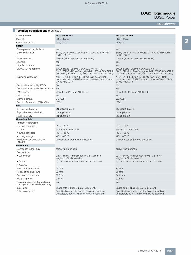
2/45Siemens ST 70 · 2015
2
■ Technical specifications (continued)
LOGO! logic moduleLOGO!Power
LOGO!Power
Safety
Primary/secondary isolation Yes Yes
Galvanic isolation Safety extra-low output voltage Uout acc. to EN 60950-1 and EN 50178
Safety extra-low output voltage Uout acc. to EN 60950-1 and EN 50178
Protection class Class II (without protective conductor) Class II (without protective conductor)
CE mark Yes Yes
UL/CSA approval Yes Yes
UL/cUL (CSA) approval cULus-Listed (UL 508, CSA C22.2 No. 107.1), File E197259; cURus-Recognized (UL 60950, CSA C22.2 No. 60950), File E151273, NEC class 2 (acc. to UL 1310)
cULus-Listed (UL 508, CSA C22.2 No. 107.1), File E197259; cURus-Recognized (UL 60950, CSA C22.2 No. 60950), File E151273, NEC class 2 (acc. to UL 1310)
Explosion protection ATEX (EX) II 3G Ex nA IIC T3; cCSAus (CSA C22.2 No. 213-M1987, ANSI/ISA-12.12.01-2007) Class I, Div. 2, Group ABCD, T4
ATEX (EX) II 3G Ex nA IIC T3; cCSAus (CSA C22.2 No. 213-M1987, ANSI/ISA-12.12.01-2007) Class I, Div. 2, Group ABCD, T4
Certificate of suitability IECEx No No
Certificate of suitability NEC Class 2 Yes Yes
FM approval Class I, Div. 2, Group ABCD, T4 Class I, Div. 2, Group ABCD, T4
CB approval Yes Yes
Marine approval GL, ABS GL, ABS
Degree of protection (EN 60529) IP20 IP20
EMC
Emitted interference EN 55022 Class B EN 55022 Class B
Supply harmonics limitation not applicable not applicable
Noise immunity EN 61000-6-2 EN 61000-6-2
Operating data
Ambient temperature
• during operation -20 ... +70 °C -20 ... +70 °C
- Note with natural convection with natural convection
• during transport -40 ... +85 °C -40 ... +85 °C
• during storage -40 ... +85 °C -40 ... +85 °C
Humidity class according to EN 60721
Climate class 3K3, no condensation Climate class 3K3, no condensation
Mechanics
Connection technology screw-type terminals screw-type terminals
Connections
• Supply input L, N: 1 screw terminal each for 0.5 ... 2.5 mm² single-core/finely stranded
L, N: 1 screw terminal each for 0.5 ... 2.5 mm² single-core/finely stranded
• Output +, -: 2 screw terminals each for 0.5 ... 2.5 mm² +, -: 2 screw terminals each for 0.5 ... 2.5 mm²
• Auxiliary - -
Width of the enclosure 54 mm 72 mm
Height of the enclosure 90 mm 90 mm
Depth of the enclosure 52.6 mm 52.6 mm
Weight, approx. 0.17 kg 0.25 kg
Product property of the enclosure housing for side-by-side mounting
Yes Yes
Installation Snaps onto DIN rail EN 60715 35x7.5/15 Snaps onto DIN rail EN 60715 35x7.5/15
Other information Specifications at rated input voltage and ambient temperature +25 °C (unless otherwise specified)
Specifications at rated input voltage and ambient temperature +25 °C (unless otherwise specified)
Article number 6EP1351-1SH03 6EP1352-1SH03
Product LOGO!Power LOGO!Power
Power supply, type 15 V/1.9 A 15 V/4 A
ST70_Kap02_EN.book Seite 45 Mittwoch, 13. Mai 2015 8:41 08
© Siemens AG 2015
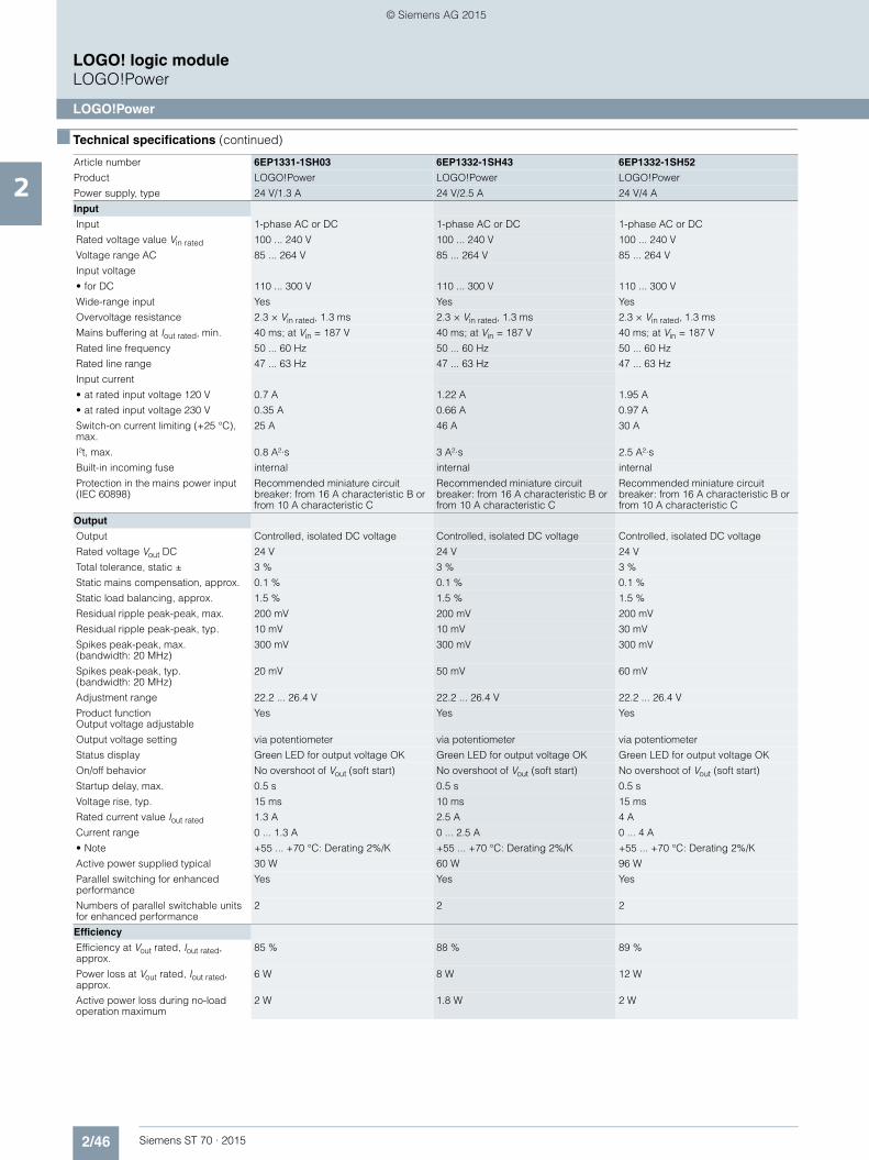
2/46 Siemens ST 70 · 2015
2
■ Technical specifications (continued)
LOGO! logic moduleLOGO!Power
LOGO!Power
Article number 6EP1331-1SH03 6EP1332-1SH43 6EP1332-1SH52
Product LOGO!Power LOGO!Power LOGO!Power
Power supply, type 24 V/1.3 A 24 V/2.5 A 24 V/4 A
Input
Input 1-phase AC or DC 1-phase AC or DC 1-phase AC or DC
Rated voltage value Vin rated 100 ... 240 V 100 ... 240 V 100 ... 240 V
Voltage range AC 85 ... 264 V 85 ... 264 V 85 ... 264 V
Input voltage
• for DC 110 ... 300 V 110 ... 300 V 110 ... 300 V
Wide-range input Yes Yes Yes
Overvoltage resistance 2.3 × Vin rated, 1.3 ms 2.3 × Vin rated, 1.3 ms 2.3 × Vin rated, 1.3 ms
Mains buffering at Iout rated, min. 40 ms; at Vin = 187 V 40 ms; at Vin = 187 V 40 ms; at Vin = 187 V
Rated line frequency 50 ... 60 Hz 50 ... 60 Hz 50 ... 60 Hz
Rated line range 47 ... 63 Hz 47 ... 63 Hz 47 ... 63 Hz
Input current
• at rated input voltage 120 V 0.7 A 1.22 A 1.95 A
• at rated input voltage 230 V 0.35 A 0.66 A 0.97 A
Switch-on current limiting (+25 °C), max.
25 A 46 A 30 A
I²t, max. 0.8 A²·s 3 A²·s 2.5 A²·s
Built-in incoming fuse internal internal internal
Protection in the mains power input (IEC 60898)
Recommended miniature circuit breaker: from 16 A characteristic B or from 10 A characteristic C
Recommended miniature circuit breaker: from 16 A characteristic B or from 10 A characteristic C
Recommended miniature circuit breaker: from 16 A characteristic B or from 10 A characteristic C
Output
Output Controlled, isolated DC voltage Controlled, isolated DC voltage Controlled, isolated DC voltage
Rated voltage Vout DC 24 V 24 V 24 V
Total tolerance, static ± 3 % 3 % 3 %
Static mains compensation, approx. 0.1 % 0.1 % 0.1 %
Static load balancing, approx. 1.5 % 1.5 % 1.5 %
Residual ripple peak-peak, max. 200 mV 200 mV 200 mV
Residual ripple peak-peak, typ. 10 mV 10 mV 30 mV
Spikes peak-peak, max. (bandwidth: 20 MHz)
300 mV 300 mV 300 mV
Spikes peak-peak, typ. (bandwidth: 20 MHz)
20 mV 50 mV 60 mV
Adjustment range 22.2 ... 26.4 V 22.2 ... 26.4 V 22.2 ... 26.4 V
Product function Output voltage adjustable
Yes Yes Yes
Output voltage setting via potentiometer via potentiometer via potentiometer
Status display Green LED for output voltage OK Green LED for output voltage OK Green LED for output voltage OK
On/off behavior No overshoot of Vout (soft start) No overshoot of Vout (soft start) No overshoot of Vout (soft start)
Startup delay, max. 0.5 s 0.5 s 0.5 s
Voltage rise, typ. 15 ms 10 ms 15 ms
Rated current value Iout rated 1.3 A 2.5 A 4 A
Current range 0 ... 1.3 A 0 ... 2.5 A 0 ... 4 A
• Note +55 ... +70 °C: Derating 2%/K +55 ... +70 °C: Derating 2%/K +55 ... +70 °C: Derating 2%/K
Active power supplied typical 30 W 60 W 96 W
Parallel switching for enhanced performance
Yes Yes Yes
Numbers of parallel switchable units for enhanced performance
2 2 2
Efficiency
Efficiency at Vout rated, Iout rated, approx.
85 % 88 % 89 %
Power loss at Vout rated, Iout rated, approx.
6 W 8 W 12 W
Active power loss during no-load operation maximum
2 W 1.8 W 2 W
ST70_Kap02_EN.book Seite 46 Mittwoch, 13. Mai 2015 8:41 08
© Siemens AG 2015
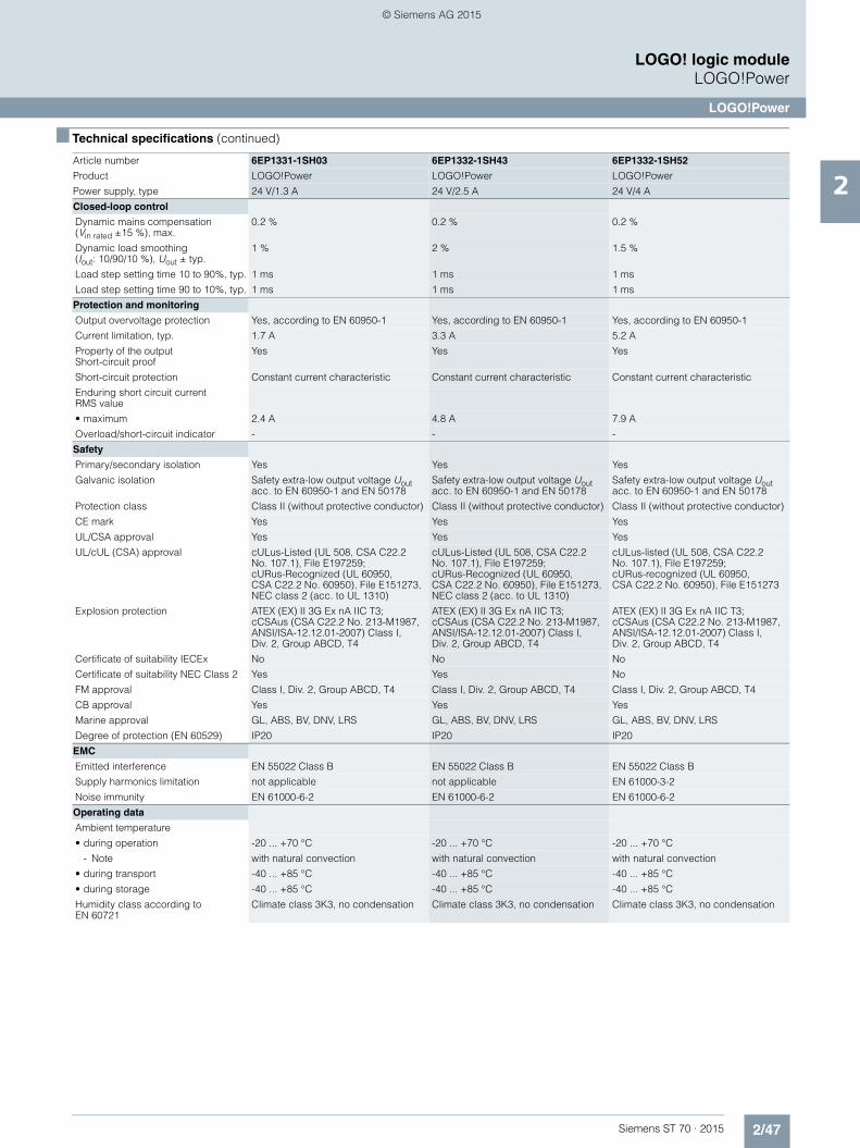
2/47Siemens ST 70 · 2015
2
■ Technical specifications (continued)
LOGO! logic moduleLOGO!Power
LOGO!Power
Closed-loop control
Dynamic mains compensation (Vin rated ±15 %), max.
0.2 % 0.2 % 0.2 %
Dynamic load smoothing (Iout: 10/90/10 %), Uout ± typ.
1 % 2 % 1.5 %
Load step setting time 10 to 90%, typ. 1 ms 1 ms 1 ms
Load step setting time 90 to 10%, typ. 1 ms 1 ms 1 ms
Protection and monitoring
Output overvoltage protection Yes, according to EN 60950-1 Yes, according to EN 60950-1 Yes, according to EN 60950-1
Current limitation, typ. 1.7 A 3.3 A 5.2 A
Property of the output Short-circuit proof
Yes Yes Yes
Short-circuit protection Constant current characteristic Constant current characteristic Constant current characteristic
Enduring short circuit current RMS value
• maximum 2.4 A 4.8 A 7.9 A
Overload/short-circuit indicator - - -
Safety
Primary/secondary isolation Yes Yes Yes
Galvanic isolation Safety extra-low output voltage Uout acc. to EN 60950-1 and EN 50178
Safety extra-low output voltage Uout acc. to EN 60950-1 and EN 50178
Safety extra-low output voltage Uout acc. to EN 60950-1 and EN 50178
Protection class Class II (without protective conductor) Class II (without protective conductor) Class II (without protective conductor)
CE mark Yes Yes Yes
UL/CSA approval Yes Yes Yes
UL/cUL (CSA) approval cULus-Listed (UL 508, CSA C22.2 No. 107.1), File E197259; cURus-Recognized (UL 60950, CSA C22.2 No. 60950), File E151273, NEC class 2 (acc. to UL 1310)
cULus-Listed (UL 508, CSA C22.2 No. 107.1), File E197259; cURus-Recognized (UL 60950, CSA C22.2 No. 60950), File E151273, NEC class 2 (acc. to UL 1310)
cULus-listed (UL 508, CSA C22.2 No. 107.1), File E197259; cURus-recognized (UL 60950, CSA C22.2 No. 60950), File E151273
Explosion protection ATEX (EX) II 3G Ex nA IIC T3; cCSAus (CSA C22.2 No. 213-M1987, ANSI/ISA-12.12.01-2007) Class I, Div. 2, Group ABCD, T4
ATEX (EX) II 3G Ex nA IIC T3; cCSAus (CSA C22.2 No. 213-M1987, ANSI/ISA-12.12.01-2007) Class I, Div. 2, Group ABCD, T4
ATEX (EX) II 3G Ex nA IIC T3; cCSAus (CSA C22.2 No. 213-M1987, ANSI/ISA-12.12.01-2007) Class I, Div. 2, Group ABCD, T4
Certificate of suitability IECEx No No No
Certificate of suitability NEC Class 2 Yes Yes No
FM approval Class I, Div. 2, Group ABCD, T4 Class I, Div. 2, Group ABCD, T4 Class I, Div. 2, Group ABCD, T4
CB approval Yes Yes Yes
Marine approval GL, ABS, BV, DNV, LRS GL, ABS, BV, DNV, LRS GL, ABS, BV, DNV, LRS
Degree of protection (EN 60529) IP20 IP20 IP20
EMC
Emitted interference EN 55022 Class B EN 55022 Class B EN 55022 Class B
Supply harmonics limitation not applicable not applicable EN 61000-3-2
Noise immunity EN 61000-6-2 EN 61000-6-2 EN 61000-6-2
Operating data
Ambient temperature
• during operation -20 ... +70 °C -20 ... +70 °C -20 ... +70 °C
- Note with natural convection with natural convection with natural convection
• during transport -40 ... +85 °C -40 ... +85 °C -40 ... +85 °C
• during storage -40 ... +85 °C -40 ... +85 °C -40 ... +85 °C
Humidity class according to EN 60721
Climate class 3K3, no condensation Climate class 3K3, no condensation Climate class 3K3, no condensation
Article number 6EP1331-1SH03 6EP1332-1SH43 6EP1332-1SH52
Product LOGO!Power LOGO!Power LOGO!Power
Power supply, type 24 V/1.3 A 24 V/2.5 A 24 V/4 A
ST70_Kap02_EN.book Seite 47 Mittwoch, 13. Mai 2015 8:41 08
© Siemens AG 2015
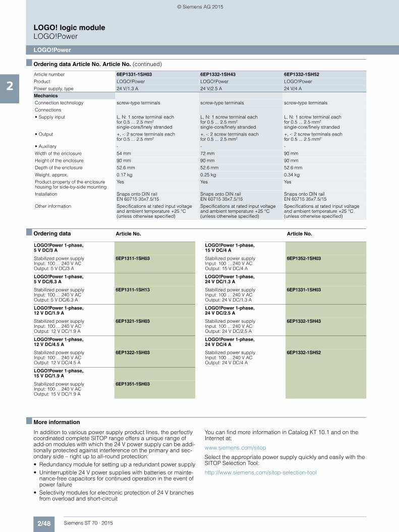
2/48 Siemens ST 70 · 2015
2
■ Ordering data Article No. Article No. (continued)
LOGO! logic moduleLOGO!Power
LOGO!Power
■ Ordering data Article No. Article No.
■ More information
In addition to various power supply product lines, the perfectly coordinated complete SITOP range offers a unique range of add-on modules with which the 24 V power supply can be addi-tionally protected against interference on the primary and sec-ondary side – right up to all-round protection:• Redundancy module for setting up a redundant power supply• Uninterruptible 24 V power supplies with batteries or mainte-
nance-free capacitors for continued operation in the event of power failure
• Selectivity modules for electronic protection of 24 V branches from overload and short-circuit
You can find more information in Catalog KT 10.1 and on the Internet at:
www.siemens.com/sitop
Select the appropriate power supply quickly and easily with the SITOP Selection Tool:
http://www.siemens.com/sitop-selection-tool
Mechanics
Connection technology screw-type terminals screw-type terminals screw-type terminals
Connections
• Supply input L, N: 1 screw terminal each for 0.5 ... 2.5 mm² single-core/finely stranded
L, N: 1 screw terminal each for 0.5 ... 2.5 mm² single-core/finely stranded
L, N: 1 screw terminal each for 0.5 ... 2.5 mm² single-core/finely stranded
• Output +, -: 2 screw terminals each for 0.5 ... 2.5 mm²
+, -: 2 screw terminals each for 0.5 ... 2.5 mm²
+, -: 2 screw terminals each for 0.5 ... 2.5 mm²
• Auxiliary - - -
Width of the enclosure 54 mm 72 mm 90 mm
Height of the enclosure 90 mm 90 mm 90 mm
Depth of the enclosure 52.6 mm 52.6 mm 52.6 mm
Weight, approx. 0.17 kg 0.25 kg 0.34 kg
Product property of the enclosure housing for side-by-side mounting
Yes Yes Yes
Installation Snaps onto DIN rail EN 60715 35x7.5/15
Snaps onto DIN rail EN 60715 35x7.5/15
Snaps onto DIN rail EN 60715 35x7.5/15
Other information Specifications at rated input voltage and ambient temperature +25 °C (unless otherwise specified)
Specifications at rated input voltage and ambient temperature +25 °C (unless otherwise specified)
Specifications at rated input voltage and ambient temperature +25 °C (unless otherwise specified)
Article number 6EP1331-1SH03 6EP1332-1SH43 6EP1332-1SH52
Product LOGO!Power LOGO!Power LOGO!Power
Power supply, type 24 V/1.3 A 24 V/2.5 A 24 V/4 A
LOGO!Power 1-phase, 5 V DC/3 A
Stabilized power supplyInput: 100 ... 240 V AC Output: 5 V DC/3 A
6EP1311-1SH03
LOGO!Power 1-phase, 5 V DC/6.3 A
Stabilized power supplyInput: 100 ... 240 V AC Output: 5 V DC/6.3 A
6EP1311-1SH13
LOGO!Power 1-phase, 12 V DC/1.9 A
Stabilized power supplyInput: 100 ... 240 V AC Output: 12 V DC/1.9 A
6EP1321-1SH03
LOGO!Power 1-phase, 12 V DC/4.5 A
Stabilized power supplyInput: 100 ... 240 V AC Output: 12 V DC/4.5 A
6EP1322-1SH03
LOGO!Power 1-phase, 15 V DC/1.9 A
Stabilized power supplyInput: 100 ... 240 V AC Output: 15 V DC/1.9 A
6EP1351-1SH03
LOGO!Power 1-phase, 15 V DC/4 A
Stabilized power supplyInput: 100 ... 240 V AC Output: 15 V DC/4 A
6EP1352-1SH03
LOGO!Power 1-phase, 24 V DC/1.3 A
Stabilized power supplyInput: 100 ... 240 V AC Output: 24 V DC/1.3 A
6EP1331-1SH03
LOGO!Power 1-phase, 24 V DC/2.5 A
Stabilized power supplyInput: 100 ... 240 V AC Output: 24 V DC/2.5 A
6EP1332-1SH43
LOGO!Power 1-phase, 24 V DC/4 A
Stabilized power supplyInput: 100 ... 240 V AC Output: 24 V DC/4 A
6EP1332-1SH52
ST70_Kap02_EN.book Seite 48 Mittwoch, 13. Mai 2015 8:41 08
© Siemens AG 2015
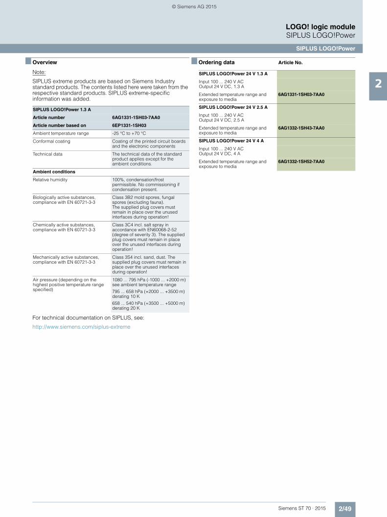
2/49Siemens ST 70 · 2015
2
LOGO! logic moduleSIPLUS LOGO!Power
SIPLUS LOGO!Power
■ Overview
Note:
SIPLUS extreme products are based on Siemens Industry standard products. The contents listed here were taken from the respective standard products. SIPLUS extreme-specific information was added.
For technical documentation on SIPLUS, see:
http://www.siemens.com/siplus-extreme
■ Ordering data Article No.
SIPLUS LOGO!Power 1.3 A
Article number 6AG1331-1SH03-7AA0
Article number based on 6EP1331-1SH03
Ambient temperature range -25 °C to +70 °C
Conformal coating Coating of the printed circuit boards and the electronic components
Technical data The technical data of the standard product applies except for the ambient conditions.
Ambient conditions
Relative humidity 100%, condensation/frost permissible. No commissioning if condensation present.
Biologically active substances, compliance with EN 60721-3-3
Class 3B2 mold spores, fungal spores (excluding fauna). The supplied plug covers must remain in place over the unused interfaces during operation!
Chemically active substances, compliance with EN 60721-3-3
Class 3C4 incl. salt spray in accordance with EN60068-2-52 (degree of severity 3). The supplied plug covers must remain in place over the unused interfaces during operation!
Mechanically active substances, compliance with EN 60721-3-3
Class 3S4 incl. sand, dust. The supplied plug covers must remain in place over the unused interfaces during operation!
Air pressure (depending on the highest positive temperature range specified)
1080 ... 795 hPa (-1000 ... +2000 m) see ambient temperature range
795 ... 658 hPa (+2000 ... +3500 m) derating 10 K
658 ... 540 hPa (+3500 ... +5000 m) derating 20 K
SIPLUS LOGO!Power 24 V 1.3 A
Input 100 ... 240 V ACOutput 24 V DC, 1.3 A
Extended temperature range and exposure to media
6AG1331-1SH03-7AA0
SIPLUS LOGO!Power 24 V 2.5 A
Input 100 ... 240 V ACOutput 24 V DC, 2.5 A
Extended temperature range and exposure to media
6AG1332-1SH43-7AA0
SIPLUS LOGO!Power 24 V 4 A
Input 100 ... 240 V ACOutput 24 V DC, 4 A
Extended temperature range and exposure to media
6AG1332-1SH52-7AA0
ST70_Kap02_EN.book Seite 49 Mittwoch, 13. Mai 2015 8:41 08
© Siemens AG 2015
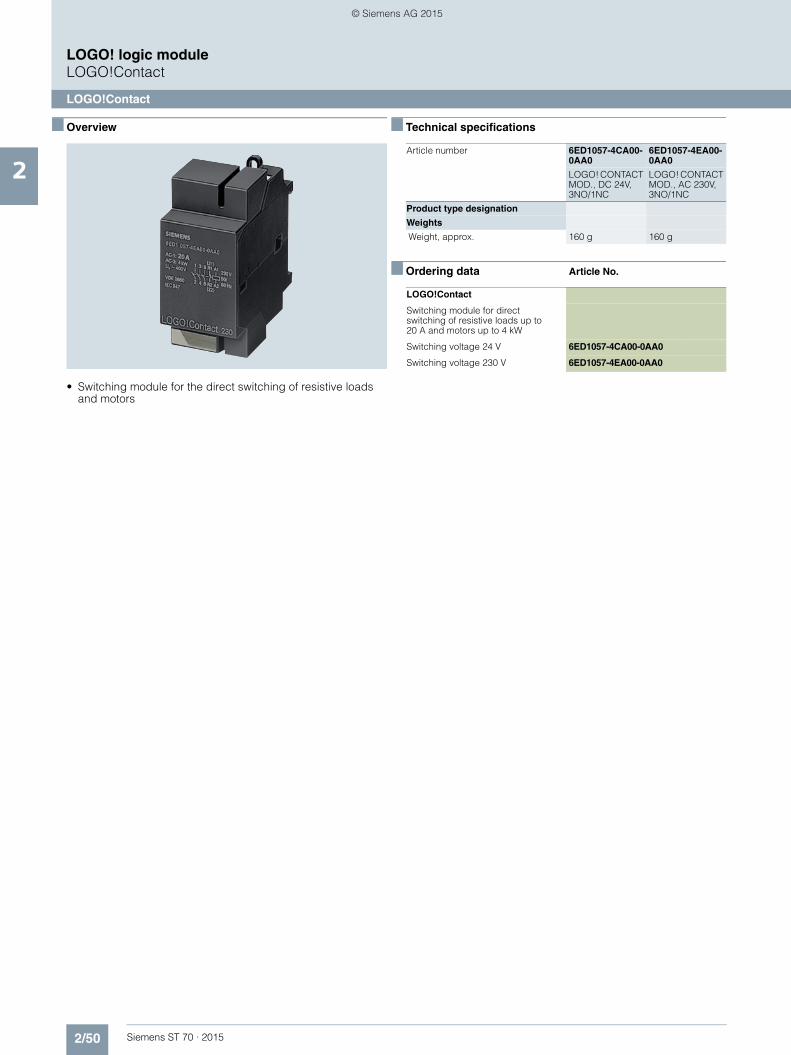
2/50 Siemens ST 70 · 2015
2
LOGO! logic moduleLOGO!Contact
LOGO!Contact
■ Overview
• Switching module for the direct switching of resistive loads and motors
■ Technical specifications
■ Ordering data Article No.
Article number 6ED1057-4CA00-0AA0
6ED1057-4EA00-0AA0
LOGO! CONTACT MOD., DC 24V, 3NO/1NC
LOGO! CONTACT MOD., AC 230V, 3NO/1NC
Product type designation
Weights
Weight, approx. 160 g 160 g
LOGO!Contact
Switching module for direct switching of resistive loads up to 20 A and motors up to 4 kW
Switching voltage 24 V 6ED1057-4CA00-0AA0
Switching voltage 230 V 6ED1057-4EA00-0AA0
ST70_Kap02_EN.book Seite 50 Mittwoch, 13. Mai 2015 8:41 08
© Siemens AG 2015
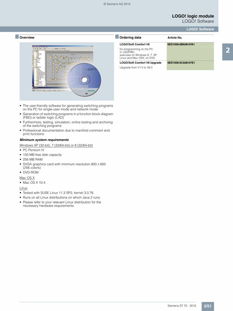
2/51Siemens ST 70 · 2015
2
LOGO! logic moduleLOGO! Software
LOGO! Software
■ Overview
• The user-friendly software for generating switching programs on the PC for single-user mode and network mode
• Generation of switching programs in a function block diagram (FBD) or ladder logic (LAD)
• Furthermore, testing, simulation, online testing and archiving of the switching programs
• Professional documentation due to manifold comment and print functions
Minimum system requirements
Windows XP (32-bit), 7 (32/64-bit) or 8 (32/64-bit)• PC Pentium IV• 150 MB free disk capacity• 256 MB RAM• SVGA graphics card with minimum resolution 800 x 600
(256 colors)• DVD-ROM
Mac OS X• Mac OS X 10.4
Linux• Tested with SUSE Linux 11.3 SP2, kernel 3.0.76• Runs on all Linux distributions on which Java 2 runs.• Please refer to your relevant Linux distribution for the
necessary hardware requirements.
■ Ordering data Article No.
LOGO!Soft Comfort V8 6ED1058-0BA08-0YA1
for programming on the PC in LAD/FBD; executes on Windows 8, 7, XP, Linux and Mac OSX; on DVD
LOGO!Soft Comfort V8 Upgrade 6ED1058-0CA08-0YE1
Upgrade from V1.0 to V8.0
ST70_Kap02_EN.book Seite 51 Mittwoch, 13. Mai 2015 8:41 08
© Siemens AG 2015

2/52 Siemens ST 70 · 2015
2
LOGO! logic moduleSIPLUS add-ons
SIPLUS LOGO! PROM
■ OverviewLOGO! PROM is the programming device for easy reproduction of up to 8 LOGO! program modules. Copying is performed from a master module or via the PC program LOGO! Soft Comfort.
LOGO! PROM supports yellow and red program modules. Only yellow modules can be used as master modules, because red modules cannot be copied due to the know-how protection im-plemented.
A multi-colored LED on each module slot provides detailed infor-mation about the status of the respective program module and the copying procedure.
■ Ordering data Article No.
■ Overview
LOGO! and SIPLUS LOGO! are designed for quick and easy mounting on standard rails. With the mounting kit, these devices can also be easily and safely installed in front panels. If the supplied washer and seals are used, the devices are reliably protected against harsh environmental conditions up to the IP65 degree of protection.
■ Ordering data Article No.
■ Overview
The SIPLUS upmiter upstream device ensures reliable operation of SIPLUS devices connected to the batteries of internal combustion engines. SIPLUS upmiter provides the devices with a constant voltage supply.
■ Ordering data Article No.
LOGO! PROM 6AG1057-1AA01-0BA6
Programming device used to simultaneously reproduce program module contents on up to 8 program modules
LOGO! mounting kits
Front panel mounting kit
Width 4 width units 6AG1057-1AA00-0AA0
Width 4 width units, with keys 6AG1057-1AA00-0AA3
Width 8 width units 6AG1057-1AA00-0AA1
Width 8 width units, with keys 6AG1057-1AA00-0AA2
SIPLUS upmiters
SIPLUS upmiter upstream device
for reliable operation when connected to the batteries of combustion engines
Output current 1.25 A (LOGO! style)
6AG1053-1AA00-2AA0
Output current 4 A (S7-300 style)
6AG1305-1AA00-2AA0
ST70_Kap02_EN.book Seite 52 Mittwoch, 13. Mai 2015 8:41 08
© Siemens AG 2015
Top Related