


Languages
Pages
Legal


.
Load Sensors Acquisition System
(LSAS) – CNRAD irradiation test
(21.09.2012 – 3.12.2012)
Mateusz Sosin
BE/ABP/SU
RADWG, 12.09.2013

Mateusz Sosin Research status of Low-Beta weighting system
Load sensors under Low-Beta quadrupoles – short introduction
Load Sensors Acquisition System (LSAS) – DUT description
Radiation levels at LSAS equipment locations
CNRAD tests
RADWG, 12.09.2013
Mateusz Sosin Research status of Low-Beta weighting system
Load sensors under Low-Beta quadrupoles
Device Under Test 12 input channels;
Each channel input range ±10mV (scaled to ±15V @ data output)
AC excitation of sensors
Main application
Monitoring of LowBeta jack load when adjusting (according to risk of lontact lost). System is not critical for the LHC operation
Strain gauge (Wheatstone bridge) load sensor (HBM MPZ1108010, sensor constant ~1.3mV/V, Uexc = 5V, 20T range, typical bridge Uout → ~ -1 .. 6.5mV)
DUT is an acquisition electronics crate, conditioning the load sensors signals and sending the measurement data via WordFIP
RADWG, 12.09.2013
Single IP side (L or R) installation layout

Mateusz Sosin Research status of Low-Beta weighting system
DUT: Load Sensors Acquisition System (LSAS)
LSAS crate (load sensors signal conditioning by Analog Devices AD7730L) Based on existing „Survey Acquisition System (SAS)” used
by BE-ABP-SU for alignment sensors measurements
FipADUC card for FIP communication and local connection by RS232 link
Self-diagnostic implemented
RADWG, 12.09.2013
FIP ADUC CARD
CONN.TAPE
LOAD SENSORS
12 CHANNEL INPUT
STAGE → 2 PCB’s:
- Upper board (6CH AD7730L)
- Main board (6CH AD7730L +
powering +control logic)
Mateusz Sosin Research status of Low-Beta weighting system
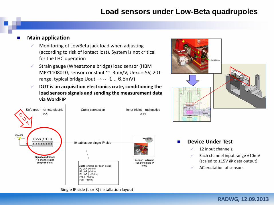
DUT: Load Sensors Acquisition System (LSAS)
AD7730L signal conditioner Analog Devices, CMOS, 24-Bit Sigma-Delta, Bridge Transducer ADC for Load Cell Applications. Equipped in digital
filters, internal calibration microcontroller. Contain ~24B of RAM.
Basic DSP abilities included (filters)
The AD7730 retains its ratiometric operation with reference voltage varying in sympathy with the analog input voltage (ADCOUT = (VIN/VREF) x Full-Scale x Scaling-Factor). Eliminate impact of excitation voltage change (cables resistances)
AC excitation of the bridge addresses many of the concerns with thermocouple, offset and drift effects encountered in dc-excited applications
RADWG, 12.09.2013

Mateusz Sosin Research status of Low-Beta weighting system
FIP ADUC
CARD
LOAD SENSORS
12 CHANNEL INPUT
STAGE - 2 PCB-s
CONN.TAPE
Semiconductors used for 12-channel input stage (2 PCB-s) of LSAS: 12 x AD7730L –Bridge Transducer for Load Cell Applications.
12xMIC4427 – Micrel, MOSFET driver – sensor supply polarization change in AC measurement mode (not tested)
1xCPLD XC95288XL – Xilinx CPLD, 288 macrocells – contains all board logic: AD7730L→ADUC834 signal multiplexer, FipADUC to ADUC834 bus interface, LED driver (not tested)
1xADUC834 – Analog Devices, ’51 based MCU – board diagnostics, AD7730L initializing & data reading, sensor measurements conversion & averaging, FipADUC communication (tested)
12xLED HLMP-1700 or HLMP-1790 (tested)
POWER SUPPLY:
4x rectifying diodes 50WQ03FN (tested)
2x IRF6215S MOSFET transistor (tested)
1x LM7805 – Linear voltage stabilizer (tested)
1x LE33 (not tested)
DUT: Load Sensors Acquisition System (LSAS)
RADWG, 12.09.2013
Tested by A.Marin as part of Survey Acquisition System – SAS (EDMS 1062166)

Mateusz Sosin Research status of Low-Beta weighting system
Load Sensors Acquisition System (LSAS) – radiation levels at
equipment location
Equipment locations: IP1: US15
IP2: UA23, UA27
IP8: UA83, UA87
IP5: UJ56 -> after LS1 UL55
Equipment quantity: Each IP -> 2 LSAS crates
LHC: 8 crates in total
RADWG, 12.09.2013
Radiation levels 2012 (according to: Radiation Levels around the LHC; P. Mala, M. Brugger, M. Calviani, A. Nordt ; ATS /Note/2013/032.
US15, UA23, UA27, UA83, UA87, UL55 are considered as non-critical)
Total Ioinizing Dose < 0.1 Gy/year
High Energy Hadron fluence < 1x107cm-2
Radiation levels considered to tests → TID 100Gy (according to: IRRADIATION D’UN CHÂSSIS SAS 1ÈRE GÉNÉNATION; A. Marin, EDMS 1062166 → SAS falirue at TID 98Gy; 1stR2E RADIATION SCHOOL & WORKSHOP Divonne, June 2nd/3rd2009; M.Brugger for the R2E Study Group)
Total Ioinizing Dose UJ56: 1-10 Gy/year
High Energy Hadron fluence UJ56: 1x10⁹ - 1x1010 cm-2
1MeV neutron equivalent UJ56: 1x10¹⁰ - 1x10¹¹

Mateusz Sosin Research status of Low-Beta weighting system RADWG, 12.09.2013
Load Sensors signal simulation – CNRAD measurements
To simulate real sensor connected to the input channel of LSAS crate – the special adapters enclosed in metal envelopes were prepared
The single adapter contained metalized-resistors circuit - representing Wheatstone bridge of original HBM MPZ1108010 load sensor
Resistor resistances were selected to have different input value on each channel (within entire range of conditioner input channels)
Main purpose of the test was to check the stability of the sensors signal over the LSAS crate irradiation

Mateusz Sosin Research status of Low-Beta weighting system
Supply voltages and currents – CNRAD measurements
IDIG
IANALOG
Supply voltages measurement before and after irradiation LSAS board logic powering, ADUC834:
+5VL, XC95288 : +3.3VL
+5VR (FipADUC powering, main supply for LSAS board logic)
AD7730L signal conditioners powering – digital and analog supply: +5VD (DVdd), +5VA (AVdd)
Current monitoring for board logic and conditioners (IDIG, IANALOG) IDIG, IANALOG current measurements using
shunt resistors (Rshunt(Q1), Rshunt(Q2)) and differential op-amp circuitry were implememnted (conversion of IDIG, IANALOG to FipADUC ADC voltage inputs).
RADWG, 12.09.2013
LOST PROBABLY BECAUSE OF
FAULT DURING INSLATTATION IN
CNRAD.
UNFORTUNATELY DETECTED AFTER
IRRADIATION STARTED
Mateusz Sosin Research status of Low-Beta weighting system
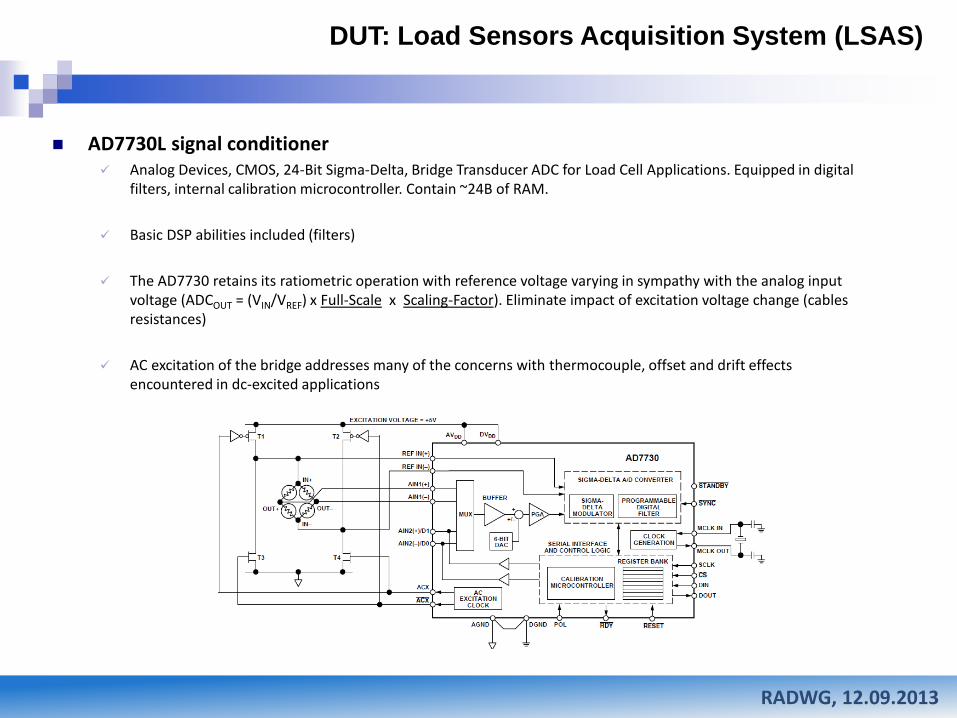
LSAS installation – CNRAD measurements
RADWG, 12.09.2013
The LSAS test crate was installed in TSG45 – position 432 in order to reach TID of 100Gy
LSAS crate data acquisition was realized by Front End Computer using 31.5kHz WordFIP connection. Input channels measurements and diagnostic events were logged on PVSS server created for the test purposes
In case of DUT functional interrupt – remote reset possibility by power supply OFF and ON was provided
Mateusz Sosin Research status of Low-Beta weighting system
LSAS – CNRAD measurements
RADWG, 12.09.2013
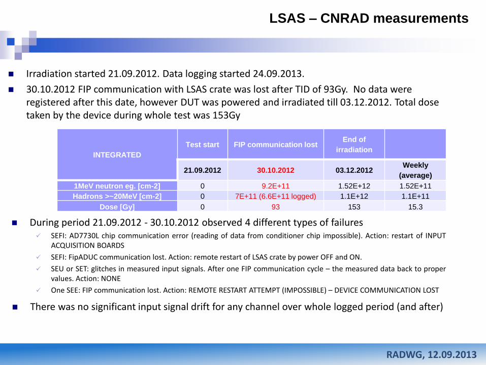
Irradiation started 21.09.2012. Data logging started 24.09.2013.
30.10.2012 FIP communication with LSAS crate was lost after TID of 93Gy. No data were registered after this date, however DUT was powered and irradiated till 03.12.2012. Total dose taken by the device during whole test was 153Gy
INTEGRATED
Test start FIP communication lost End of
irradiation
21.09.2012 30.10.2012 03.12.2012 Weekly
(average)
1MeV neutron eg. [cm-2] 0 9.2E+11 1.52E+12 1.52E+11
Hadrons >~20MeV [cm-2] 0 7E+11 (6.6E+11 logged) 1.1E+12 1.1E+11
Dose [Gy] 0 93 153 15.3
During period 21.09.2012 - 30.10.2012 observed 4 different types of failures SEFI: AD7730L chip communication error (reading of data from conditioner chip impossible). Action: restart of INPUT
ACQUISITION BOARDS
SEFI: FipADUC communication lost. Action: remote restart of LSAS crate by power OFF and ON.
SEU or SET: glitches in measured input signals. After one FIP communication cycle – the measured data back to proper values. Action: NONE
One SEE: FIP communication lost. Action: REMOTE RESTART ATTEMPT (IMPOSSIBLE) – DEVICE COMMUNICATION LOST
There was no significant input signal drift for any channel over whole logged period (and after)
Mateusz Sosin Research status of Low-Beta weighting system
Signal stability of LSAS input channels – CNRAD measurements
RADWG, 12.09.2013
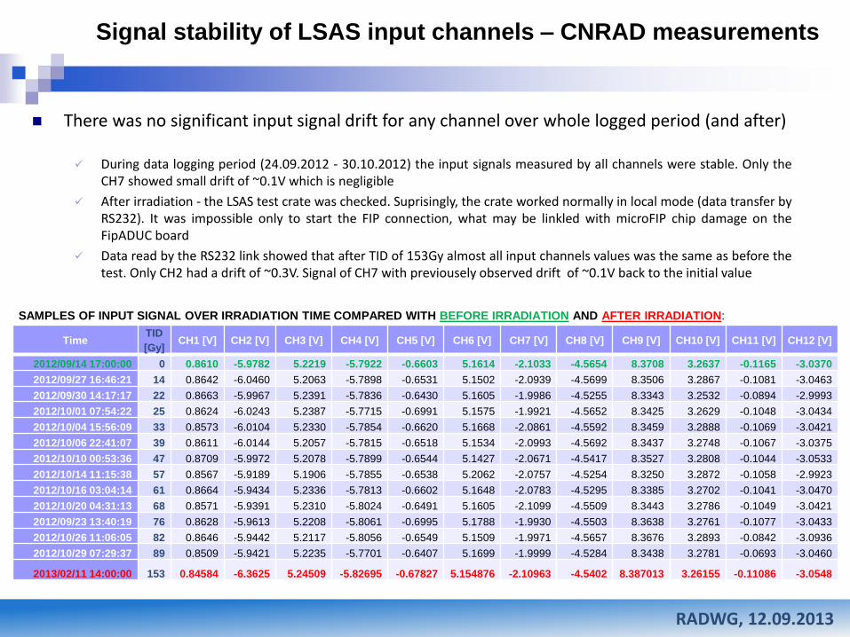
There was no significant input signal drift for any channel over whole logged period (and after)
During data logging period (24.09.2012 - 30.10.2012) the input signals measured by all channels were stable. Only the CH7 showed small drift of ~0.1V which is negligible
After irradiation - the LSAS test crate was checked. Suprisingly, the crate worked normally in local mode (data transfer by RS232). It was impossible only to start the FIP connection, what may be linkled with microFIP chip damage on the FipADUC board
Data read by the RS232 link showed that after TID of 153Gy almost all input channels values was the same as before the test. Only CH2 had a drift of ~0.3V. Signal of CH7 with previousely observed drift of ~0.1V back to the initial value
Time
TID
[Gy] CH1 [V] CH2 [V] CH3 [V] CH4 [V] CH5 [V] CH6 [V] CH7 [V] CH8 [V] CH9 [V] CH10 [V] CH11 [V] CH12 [V]
2012/09/14 17:00:00 0 0.8610 -5.9782 5.2219 -5.7922 -0.6603 5.1614 -2.1033 -4.5654 8.3708 3.2637 -0.1165 -3.0370
2012/09/27 16:46:21 14 0.8642 -6.0460 5.2063 -5.7898 -0.6531 5.1502 -2.0939 -4.5699 8.3506 3.2867 -0.1081 -3.0463
2012/09/30 14:17:17 22 0.8663 -5.9967 5.2391 -5.7836 -0.6430 5.1605 -1.9986 -4.5255 8.3343 3.2532 -0.0894 -2.9993
2012/10/01 07:54:22 25 0.8624 -6.0243 5.2387 -5.7715 -0.6991 5.1575 -1.9921 -4.5652 8.3425 3.2629 -0.1048 -3.0434
2012/10/04 15:56:09 33 0.8573 -6.0104 5.2330 -5.7854 -0.6620 5.1668 -2.0861 -4.5592 8.3459 3.2888 -0.1069 -3.0421
2012/10/06 22:41:07 39 0.8611 -6.0144 5.2057 -5.7815 -0.6518 5.1534 -2.0993 -4.5692 8.3437 3.2748 -0.1067 -3.0375
2012/10/10 00:53:36 47 0.8709 -5.9972 5.2078 -5.7899 -0.6544 5.1427 -2.0671 -4.5417 8.3527 3.2808 -0.1044 -3.0533
2012/10/14 11:15:38 57 0.8567 -5.9189 5.1906 -5.7855 -0.6538 5.2062 -2.0757 -4.5254 8.3250 3.2872 -0.1058 -2.9923
2012/10/16 03:04:14 61 0.8664 -5.9434 5.2336 -5.7813 -0.6602 5.1648 -2.0783 -4.5295 8.3385 3.2702 -0.1041 -3.0470
2012/10/20 04:31:13 68 0.8571 -5.9391 5.2310 -5.8024 -0.6491 5.1605 -2.1099 -4.5509 8.3443 3.2786 -0.1049 -3.0421
2012/09/23 13:40:19 76 0.8628 -5.9613 5.2208 -5.8061 -0.6995 5.1788 -1.9930 -4.5503 8.3638 3.2761 -0.1077 -3.0433
2012/10/26 11:06:05 82 0.8646 -5.9442 5.2117 -5.8056 -0.6549 5.1509 -1.9971 -4.5657 8.3676 3.2893 -0.0842 -3.0936
2012/10/29 07:29:37 89 0.8509 -5.9421 5.2235 -5.7701 -0.6407 5.1699 -1.9999 -4.5284 8.3438 3.2781 -0.0693 -3.0460
2013/02/11 14:00:00 153 0.84584 -6.3625 5.24509 -5.82695 -0.67827 5.154876 -2.10963 -4.5402 8.387013 3.26155 -0.11086 -3.0548
SAMPLES OF INPUT SIGNAL OVER IRRADIATION TIME COMPARED WITH BEFORE IRRADIATION AND AFTER IRRADIATION:
Mateusz Sosin Research status of Low-Beta weighting system
Single Event Functional Interrupt – CNRAD measurements
RADWG, 12.09.2013
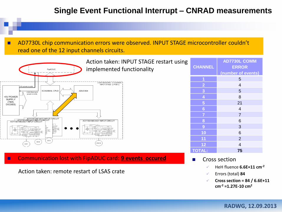
AD7730L chip communication errors were observed. INPUT STAGE microcontroller couldn’t read one of the 12 input channels circuits.
CHANNEL
AD7730L COMM
ERROR
(number of events)
1 5
2 4
3 5
4 8
5 21
6 4
7 7
8 6
9 3
10 6
11 2
12 4
TOTAL: 75
Action taken: INPUT STAGE restart using implemented functionality
Communication lost with FipADUC card: 9 events occured
Action taken: remote restart of LSAS crate
Cross section HeH fluence 6.6E+11 cm-2
Errors (total) 84
Cross section = 84 / 6.6E+11 cm-2 =1.27E-10 cm2

Mateusz Sosin Research status of Low-Beta weighting system
1
2
3 4
5
Single Event Transient or Single Event Upset – CNRAD
measurements
RADWG, 12.09.2013
Glitches were observed within the input channels measurement data. Glitches appeared only for single FIP cycle. At the next cycle signal returned to correct value
CHANNEL Glitches observed
(number of events)
1 32
2 30
3 30
4 59
5 67
6 32
7 71
8 105
9 23
10 33
11 34
12 51
TOTAL: 567
Possible reasons (1) Single Effect Transient (SET) in AD7730L internal analog cirquitry
(2) Single Effect Upset (SEU) (bit switch) in AD7730L internal RAM or communication register
(3) SEU in in INPUT STAGE microcontroller memory
(4) SEU in XC95288 output data register
(5) SEU in FipADUC card chips memories
Action taken: NONE
Non critical for the system functionality
Cross section HeH fluence 6.6E+11 cm-2
Errors (total) 567
Cross section = 567/ 6.6E+11 cm-2 =8.6E-10 cm2
Mateusz Sosin Research status of Low-Beta weighting system RADWG, 12.09.2013
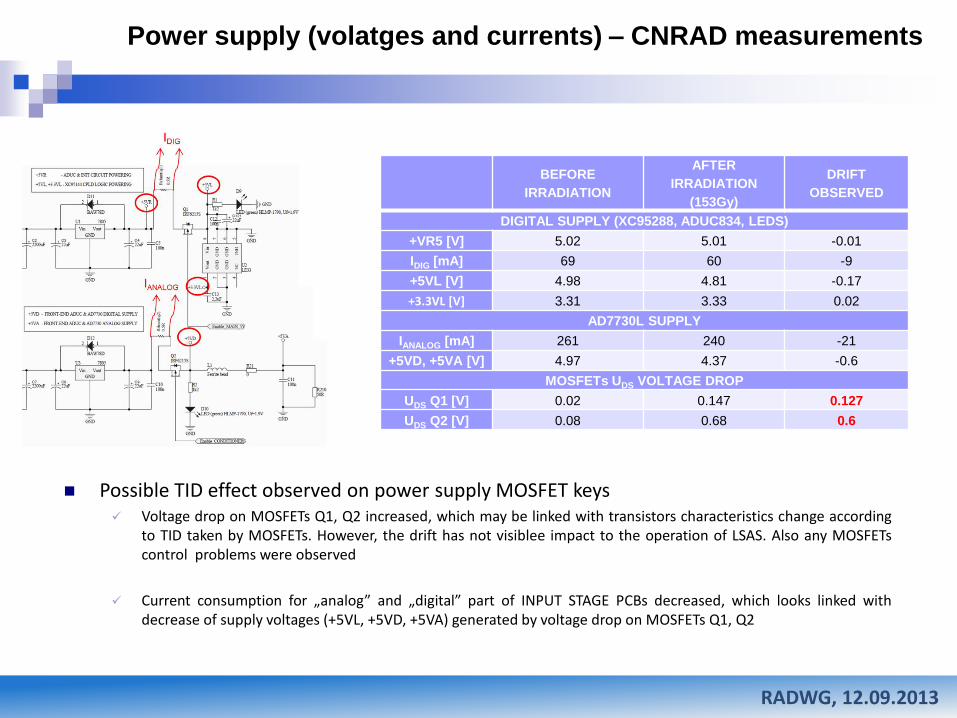
Possible TID effect observed on power supply MOSFET keys Voltage drop on MOSFETs Q1, Q2 increased, which may be linked with transistors characteristics change according
to TID taken by MOSFETs. However, the drift has not visiblee impact to the operation of LSAS. Also any MOSFETs control problems were observed
Current consumption for „analog” and „digital” part of INPUT STAGE PCBs decreased, which looks linked with decrease of supply voltages (+5VL, +5VD, +5VA) generated by voltage drop on MOSFETs Q1, Q2
BEFORE
IRRADIATION
AFTER
IRRADIATION
(153Gy)
DRIFT
OBSERVED
DIGITAL SUPPLY (XC95288, ADUC834, LEDS)
+VR5 [V] 5.02 5.01 -0.01
IDIG [mA] 69 60 -9
+5VL [V] 4.98 4.81 -0.17
+3.3VL [V] 3.31 3.33 0.02
AD7730L SUPPLY
IANALOG [mA] 261 240 -21
+5VD, +5VA [V] 4.97 4.37 -0.6
MOSFETs UDS VOLTAGE DROP
UDS Q1 [V] 0.02 0.147 0.127
UDS Q2 [V] 0.08 0.68 0.6
Power supply (volatges and currents) – CNRAD measurements
Mateusz Sosin Research status of Low-Beta weighting system
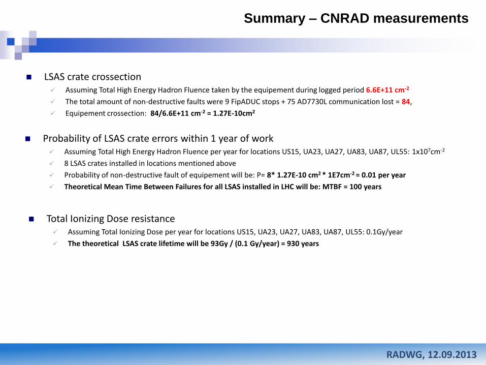
Summary – CNRAD measurements
RADWG, 12.09.2013
LSAS crate crossection Assuming Total High Energy Hadron Fluence taken by the equipement during logged period 6.6E+11 cm-2
The total amount of non-destructive faults were 9 FipADUC stops + 75 AD7730L communication lost = 84,
Equipement crossection: 84/6.6E+11 cm-2 = 1.27E-10cm2
Probability of LSAS crate errors within 1 year of work Assuming Total High Energy Hadron Fluence per year for locations US15, UA23, UA27, UA83, UA87, UL55: 1x107cm-2
8 LSAS crates installed in locations mentioned above
Probability of non-destructive fault of equipement will be: P= 8* 1.27E-10 cm2 * 1E7cm-2 = 0.01 per year
Theoretical Mean Time Between Failures for all LSAS installed in LHC will be: MTBF = 100 years
Total Ionizing Dose resistance Assuming Total Ionizing Dose per year for locations US15, UA23, UA27, UA83, UA87, UL55: 0.1Gy/year
The theoretical LSAS crate lifetime will be 93Gy / (0.1 Gy/year) = 930 years
Top Related