


Languages
Pages
Legal


LIGHTWEIGHT CAPABILITY DOMAINS: TOWARD
DECOMPOSING THE LINUX KERNEL
by
Charles Jacobsen
A thesis submitted to the faculty ofThe University of Utah
in partial fulfillment of the requirements for the degree of
Master of Science
in
Computer Science
School of Computing
The University of Utah
December 2016

Copyright c© Charles Jacobsen 2016
All Rights Reserved
T h e U n i v e r s i t y o f U t a h G r a d u a t e S c h o o l
STATEMENT OF THESIS APPROVAL
The thesis of Charles Jacobsen
has been approved by the following supervisory committee members:
Anton Burtsev , Chair 06/13/2016Date Approved
Zvonimir Rakamaric , Member 06/10/2016Date Approved
Ryan Stutsman , Member 06/13/2016Date Approved
and by Ross Whitaker , Chair/Dean of
the Department/College/School of Computing
and by David B. Kieda, Dean of The Graduate School.

ABSTRACT
Many of the operating system kernels we use today are monolithic. They consist of
numerous file systems, device drivers, and other subsystems interacting with no isolation
and full trust. As a result, a vulnerability or bug in one part of a kernel can compromise
an entire machine. Our work is motivated by the following observations: (1) introducing
some form of isolation into the kernel can help confine the effects of faulty code, and (2)
modern hardware platforms are better suited for a decomposed kernel than platforms of the
past. Platforms today consist of numerous cores, large nonuniform memories, and processor
interconnects that resemble a miniature distributed system. We argue that kernels and
hypervisors must eventually evolve beyond their current symmetric mulitprocessing (SMP)
design toward a corresponding distributed design.
But the path to this goal is not easy. Building such a kernel from scratch that has the
same capabilities as an equivalent monolithic kernel could take years of effort. In this work,
we explored the feasibility of incrementally isolating subsystems in the Linux kernel as a
path toward a distributed kernel. We developed a design and techniques for moving kernel
modules into strongly isolated domains in a way that is transparent to existing code, and
we report on the feasibility of our approach.

CONTENTS
ABSTRACT . . . . . . . . . . . . . . . . . . . . . . . . . . . . . . . . . . . . . . . . . . . . . . . . . . . . . . . . iii
LIST OF FIGURES . . . . . . . . . . . . . . . . . . . . . . . . . . . . . . . . . . . . . . . . . . . . . . . . . vi
ACKNOWLEDGMENTS . . . . . . . . . . . . . . . . . . . . . . . . . . . . . . . . . . . . . . . . . . . . ix
CHAPTERS
1. INTRODUCTION . . . . . . . . . . . . . . . . . . . . . . . . . . . . . . . . . . . . . . . . . . . . . . . 1
1.1 Motivation . . . . . . . . . . . . . . . . . . . . . . . . . . . . . . . . . . . . . . . . . . . . . . . . . . . . 11.2 Our Approach . . . . . . . . . . . . . . . . . . . . . . . . . . . . . . . . . . . . . . . . . . . . . . . . . 21.3 Outline . . . . . . . . . . . . . . . . . . . . . . . . . . . . . . . . . . . . . . . . . . . . . . . . . . . . . . 9
2. LCD MICROKERNEL . . . . . . . . . . . . . . . . . . . . . . . . . . . . . . . . . . . . . . . . . . . 10
2.1 Overview . . . . . . . . . . . . . . . . . . . . . . . . . . . . . . . . . . . . . . . . . . . . . . . . . . . . . 102.2 LCD Microkernel Objects . . . . . . . . . . . . . . . . . . . . . . . . . . . . . . . . . . . . . . . . 112.3 Capability Access Control . . . . . . . . . . . . . . . . . . . . . . . . . . . . . . . . . . . . . . . . 122.4 LCD Microkernel Interface . . . . . . . . . . . . . . . . . . . . . . . . . . . . . . . . . . . . . . . 17
3. THE LIBLCD INTERFACE, LIBLCD, AND KLIBLCD . . . . . . . . . . . . . 21
3.1 Overview . . . . . . . . . . . . . . . . . . . . . . . . . . . . . . . . . . . . . . . . . . . . . . . . . . . . . 213.2 The LIBLCD Interface . . . . . . . . . . . . . . . . . . . . . . . . . . . . . . . . . . . . . . . . . . 213.3 liblcd . . . . . . . . . . . . . . . . . . . . . . . . . . . . . . . . . . . . . . . . . . . . . . . . . . . . . . . . 293.4 kliblcd . . . . . . . . . . . . . . . . . . . . . . . . . . . . . . . . . . . . . . . . . . . . . . . . . . . . . . . 31
4. DECOMPOSITION TECHNIQUES . . . . . . . . . . . . . . . . . . . . . . . . . . . . . . . 33
4.1 Overview . . . . . . . . . . . . . . . . . . . . . . . . . . . . . . . . . . . . . . . . . . . . . . . . . . . . . 334.2 Lightweight Interposition Layers . . . . . . . . . . . . . . . . . . . . . . . . . . . . . . . . . . . 334.3 Decomposing Linux Inside the Source Tree . . . . . . . . . . . . . . . . . . . . . . . . . . . 344.4 Decomposing Function Calls . . . . . . . . . . . . . . . . . . . . . . . . . . . . . . . . . . . . . . 364.5 Handling Shared Objects . . . . . . . . . . . . . . . . . . . . . . . . . . . . . . . . . . . . . . . . 414.6 Sharing Strings and Memory Buffers . . . . . . . . . . . . . . . . . . . . . . . . . . . . . . . 464.7 Related and Future Work . . . . . . . . . . . . . . . . . . . . . . . . . . . . . . . . . . . . . . . . 47
5. CASE STUDY: ISOLATING PMFS . . . . . . . . . . . . . . . . . . . . . . . . . . . . . . . 48
5.1 Overview . . . . . . . . . . . . . . . . . . . . . . . . . . . . . . . . . . . . . . . . . . . . . . . . . . . . . 485.2 PMFS Initialization and Tear Down . . . . . . . . . . . . . . . . . . . . . . . . . . . . . . . . 505.3 PMFS Mounting and Unmounting . . . . . . . . . . . . . . . . . . . . . . . . . . . . . . . . . 525.4 Conclusion . . . . . . . . . . . . . . . . . . . . . . . . . . . . . . . . . . . . . . . . . . . . . . . . . . . . 54

6. RELATED WORK . . . . . . . . . . . . . . . . . . . . . . . . . . . . . . . . . . . . . . . . . . . . . . 56
7. CONCLUSION . . . . . . . . . . . . . . . . . . . . . . . . . . . . . . . . . . . . . . . . . . . . . . . . . . 59
REFERENCES . . . . . . . . . . . . . . . . . . . . . . . . . . . . . . . . . . . . . . . . . . . . . . . . . . . . . 61
v

LIST OF FIGURES
1.1 The ext3 filesystem and NVMe device driver are installed inside Intel VT-xcontainers. These are managed by a microkernel that is installed in the Linuxkernel. User-level applications like the bash shell and SSH server operate as before. 3
1.2 The ext3 LCD is mapping a page of host RAM into its address space, using thecapability-mediated interface provided by the microkernel. . . . . . . . . . . . . . . . . . 5
1.3 The ext3 LCD is sending a synchronous IPC message to the NVMe LCD. . . . . . 5
1.4 The ext3 LCD is sending an asynchronous IPC message to the NVMe LCD.Storing the message in a cacheline-aligned slot will trigger a set of cache coher-ence protocol messages that effectively transfer the message from the ext3 LCDcore’s cache to the NVMe’s. . . . . . . . . . . . . . . . . . . . . . . . . . . . . . . . . . . . . . . . . . 6
1.5 The NVMe LCD is servicing two outstanding I/O requests. There are two AC“threads,” shown in red and blue. The red thread has blocked, waiting for I/Oto complete. The blue thread is currently executing and is sending a response fora completed I/O request. Each thread is using a separate branch of the cactusstack, but sharing the “trunk”. . . . . . . . . . . . . . . . . . . . . . . . . . . . . . . . . . . . . . . . 7
1.6 The ext3 module is installed inside an LCD. When it invokes register fs, the gluecode intercepts the call and translates it into IPC to the nonisolated part of thekernel. The glue in the nonisolated part receives the IPC message and invokesthe real register fs function. . . . . . . . . . . . . . . . . . . . . . . . . . . . . . . . . . . . . . . . . . 8
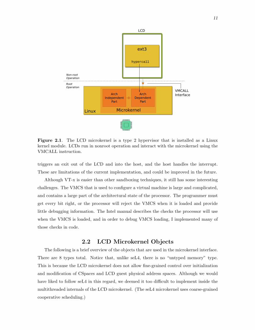
2.1 The LCD microkernel is a type 2 hypervisor that is installed as a Linux kernelmodule. LCDs run in nonroot operation and interact with the microkernel usingthe VMCALL instruction. . . . . . . . . . . . . . . . . . . . . . . . . . . . . . . . . . . . . . . . . . . . 11
2.2 A CSpace with a depth of 4 and table width of 8. In each table node in the tree,the first four slots are for storing capabilities, and the second four slots are forpointers to further tables in the CSpace. There are two capabilities shown: Onefor a page of RAM, one for a synchronous IPC endpoint. The first slot in theroot is never occupied. The maximum number of capabilities one could storein this CSpace is therefore 339 (some tables have not been instantiated in thisCSpace). . . . . . . . . . . . . . . . . . . . . . . . . . . . . . . . . . . . . . . . . . . . . . . . . . . . . . . . . 14
2.3 A Cptr is a 64-bit integer. The bit layout of a Cptr is determined by the CSpaceconfiguration, as shown, for a CSpace depth of k and node table size of t. Notethat this limits the possible configurations for CSpaces. All of the bits need tofit into a 64-bit integer. . . . . . . . . . . . . . . . . . . . . . . . . . . . . . . . . . . . . . . . . . . . . . 15

2.4 The figure shows three CSpaces for A, B, and C. A has granted B a capability,so there is a parent-child relationship between A’s capability and B’s. B has alsogranted a capability to the same object to C, so there is a further parent-childrelationship between those two. If A revokes access rights, it will revoke rightsto both B and C. . . . . . . . . . . . . . . . . . . . . . . . . . . . . . . . . . . . . . . . . . . . . . . . . . . 16
2.5 The User Thread Control Block (UTCB) has 8 scalar registers and 8 Cptrregisters for capabilities. The number of registers is configurable, and no attempthas been made to map them to machine registers. . . . . . . . . . . . . . . . . . . . . . . . . 18
3.1 The LCD guest physical address space is split into regions dedicated for certainmemory types and objects. Only the low 512 GBs are occupied. This memoryarea is mapped into the high 512 GBs in the LCD’s guest virtual address space. 23
3.2 The LCD has 4 memory objects mapped in its address space (shown in differentcolors), in the corresponding memory regions for their type (shown in lightgreen). The address ranges where each memory object is mapped along withthe cptr for the memory object are stored in a resource tree (color coded). Forexample, the blue memory object is mapped at address range [10, 19] and has acorresponding node in the resource tree. . . . . . . . . . . . . . . . . . . . . . . . . . . . . . . . . 26
3.3 The metadata for an instance of the generalized buddy allocator is shown.The memory region for which the allocator is being used is on the right. Themetadata consists of three parts: a structure, free lists, and an array of structlcd page blocks. Each struct lcd page block corresponds to a chunk of memoryof size 2min order pages. . . . . . . . . . . . . . . . . . . . . . . . . . . . . . . . . . . . . . . . . . . . . . 28
4.1 Function calls to and from the VFS and ext3 module are transparently translatedinto RPC. . . . . . . . . . . . . . . . . . . . . . . . . . . . . . . . . . . . . . . . . . . . . . . . . . . . . . . . 38
4.2 The VFS glue code sets up a duplicate of a trampoline function along with hiddenarguments on the heap so that it can redirect the function pointer invocation tothe real target inside the ext3 module. . . . . . . . . . . . . . . . . . . . . . . . . . . . . . . . . . 40
4.3 The VFS call to ext3’s foo function will trigger numerous domain crossings. Leafdomain crossings are shown in green. . . . . . . . . . . . . . . . . . . . . . . . . . . . . . . . . . . 42
4.4 The objects used in the VFS interface are connected in a complex graph. Thefigure shows a simplified example. The yellow squares are the generic objectsused in the VFS interface, while the blue squares are the filesystem-specific data(ext3 in this case). A pointer to the file object in the figure may be passed asan argument, for example, but the callee may access many of the other objectsin the graph during the function call. . . . . . . . . . . . . . . . . . . . . . . . . . . . . . . . . . . 44
4.5 The VFS and ext3 have their own private replica of the super block and inodeobjects shown. Glue code on both sides maintains a CSpace that is used totranslate remote references (Cptrs) into local pointers. The objects themselvesare wrapped in container structs, in which the glue code can store per-objectmetadata (shown in blue) like remote references. . . . . . . . . . . . . . . . . . . . . . . . . . 45
vii

4.6 The VFS and ext3 filesystem share an inode object. The white blocks arenonconcurrent code sections– they may be critical sections surrounded by a lock,or frames in a call graph that criss crosses back and forth. The fields of the inodethat are accessed are shown. The field values are shipped in RPC messages atthe right time so that the code works properly. Note that the size field valuecould have been sent in the earlier RPC, but the VFS doesn’t access this fielduntil later. . . . . . . . . . . . . . . . . . . . . . . . . . . . . . . . . . . . . . . . . . . . . . . . . . . . . . . . 47
5.1 The figure shows how user-level applications access files and the componentsinvolved. . . . . . . . . . . . . . . . . . . . . . . . . . . . . . . . . . . . . . . . . . . . . . . . . . . . . . . . . 49
5.2 There are three components in the system in which PMFS is isolated: thePMFS LCD (far right), the VFS thread, and a setup module. There are threecommunication channels: a synchronous channel that the VFS thread listens onspecifically for register filesytem invocations (green), and a pair of synchronousand asynchronous channels PMFS and the VFS use to communicate with eachother (red). . . . . . . . . . . . . . . . . . . . . . . . . . . . . . . . . . . . . . . . . . . . . . . . . . . . . . . 51
5.3 PMFS initialization and tear down dependencies. . . . . . . . . . . . . . . . . . . . . . . . . 51
5.4 The criss cross call pattern in the call to PMFS’s mount function. . . . . . . . . . . . 55
viii

ACKNOWLEDGMENTS
I would like to thank my advisor, Anton Burtsev, for the guidance and motivation he
provided me in this work. I would also like to thank the other students on our team who
contributed to this work: Weibin Sun, Muktesh Khole, Scott Bauer, Sarah Spall, Michael
Quigley, Jithu Joseph, and Abhiram Balasubramanian. The research presented in this
thesis was supported by the National Science Foundation under Grants No. 1319076 and
No. 1527526, and by a Google Faculty Fellowship.

CHAPTER 1
INTRODUCTION
1.1 Motivation
Many of the operating systems we use today are monolithic [25, 24, 41, 21, 23]. They
consist of numerous components–file systems, device drivers, network stacks–all tightly in-
terconnected as a shared memory program. There are no boundaries that prevent malicious
or buggy code in one part of the operating system from interfering with another.
Since bugs and vulnerabilities in operating systems are common, this is a real problem.
For example, the Common Vulnerabilities and Exposures (CVE) database lists nearly 400
vulnerabilities for the Linux kernel over the past few years [30]. These vulnerabilities can
be exploited by an attacker to take down or control an entire machine. It is unlikely that
things will change on their own: These operating systems consist of millions of lines of
code that is constantly evolving as new file systems and device drivers are added and the
operating system as a whole adapts to changing hardware [31]. Yet, despite the risks, we
continue to use monolithic operating systems in the core infrastructure of clouds, mobile
devices, autonomous cars, desktops, routers and switches, and beyond [26, 21, 16, 41, 29].
We argue that it is time to reconsider a microkernel design that isolates kernel subsys-
tems. Hardware platforms today consist of numerous cores and large nonuniform memories,
all linked together by an interconnect. Such platforms have been called “distributed systems
in the small,” in which memory and device access latencies are nonuniform [27]. As
established in prior work, we think this presents an opportunity to design a kernel in
which device drivers or entire subsystems are pinned to specific resources, moving toward
a distributed kernel and away from monolithic kernels that use a symmetric multiprocessor
(SMP) design [2, 27].
This architecture presents interesting, new design possibilities. High throughput, low
latency applications that rely on bare metal access or kernel bypassing, such as the Mica
key-value store [22], can naturally fit into this architecture, as they can also be pinned to
a set of cores and become just one of many other components in the distributed system.

2
Properly designed kernel subsystems can remain on the data path, rather than being pushed
out into the control plane, as in Arrakis and IX [32, 4].
But building such a distributed kernel from scratch would take years, especially one that
was comparable to a mature monolithic kernel like Linux. Decades of effort have gone into
the monolithic kernels we use today. Hence, we should try to reuse existing code, isolating
an entire subsystem or kernel modules that contain a file system or device driver. However,
it would take a lot of effort to decompose an entire monolithic kernel, and the result would
quickly become obsolete. In this work, we explored the feasibility of incrementally isolating
kernel subsystems in Linux, as a path toward a distributed kernel.
Thesis Statement: It is feasible to isolate kernel code in a way that improves
security and performance, while making minimal changes to the source.
The decomposition is carried out inside the Linux source tree itself, so that isolated code
can evolve along with the rest of the kernel and stay up to date. The next sections review
the key design choices in our architecture.
1.2 Our Approach
1.2.1 Introducing Isolation
The first part of our design is to introduce a microkernel architecture inside the Linux
kernel in a noninvasive way. We chose to run isolated code inside of Intel VT-x containers
[17]. With VT-x, we can run isolated code in a separate virtual and physical address space,
restrict access to certain privileged registers, configure how the container should handle
interrupts, and more. It gives us the ability to selectively control the hardware and devices
a container should have bare metal access to. It is also relatively easier to program compared
to other virtualization techniques (e.g., binary translation, trap and emulate, deprivileging
for user-level, and so on). We call the Intel VT-x containers Lightweight Capability Domains,
or LCDs, for reasons that will become clear in this section. Nothing is shared with or among
LCDs by default.
LCDs are managed by a type 2 hypervisor (microkernel) installed in Linux. This implies
that the rest of the system, including the nonisolated part of the kernel, boots and runs
just as before. See Figure 1.1. The resulting system is asymmetric: the nonisolated code
and microkernel are fully trusted, while the isolated code inside LCDs is not trusted.

3
sshd bash ext3 NVMe
Intel VT-x Virtual Machines
LinuxMicrokernel
Type 2 Hypervisor
User-level Applications
Figure 1.1. The ext3 filesystem and NVMe device driver are installed inside Intel VT-xcontainers. These are managed by a microkernel that is installed in the Linux kernel.User-level applications like the bash shell and SSH server operate as before.
1.2.2 Capability Access Control
The next part of our design is to use capability access control for the resources the
microkernel provides to LCDs. The microkernel exports a capability-mediated interface
that LCDs can use to allocate host RAM, create IPC channels, and so on. We chose to use
capability access control so that we can explicitly track the resources an LCD has access
to. This is the “capability” part in the LCD acronym.
We borrow from the L4 family of microkernels, seL4 in particular, in designing a
capability access control system in the LCD microkernel.1 For each LCD, the microkernel
maintains a capability space, or CSpace, that contains all of the objects the LCD has access
to, along with the access rights. The (object, access rights) pairs stored in an LCD’s
CSpace are termed capabilities. To invoke an operation on a microkernel object, an LCD
must provide a capability pointer, or Cptr, that identifies the corresponding capability in
the LCD’s CSpace. Before the microkernel carries out the operation, it will use the Cptr
to look up the object and check the access rights.
Cptrs are file-descriptor-like integer identifiers that the microkernel uses to index into
an LCD’s CSpace. If a Cptr is invalid, or refers to the wrong type of object, the LCD
microkernel will reject the operation. For example, the LCD in Figure 1.2 has a capability
to a page of RAM, and would like to map the RAM in its address space. The LCD invokes
the map function in the microkernel interface, providing the Cptr that identifies the RAM
1Note that our design is not as fine-grained as seL4: LCDs cannot construct CSpaces or VSpaces directly.

4
capability in its CSpace. The microkernel interface is implemented using the VMCALL
instruction that is part of Intel VT-x.
1.2.3 Secure, Synchronous IPC
Since code inside LCDs is isolated, it can no longer communicate with the rest of the
system using simple function calls or shared memory. We need to provide a way for LCDs to
communicate amongst themselves and with the nonisolated part of the system, so that they
can provide interfaces and gain access to facilities. These next two sections describe the two
ways LCDs communicate: synchronous IPC provided by the microkernel and asynchronous
IPC on top of restricted shared memory.
The synchronous IPC mechanism provided by the LCD microkernel is capability medi-
ated and is motivated by seL4. Two mutually distrusting LCDs can use it to communicate,
synchronize, and grant capabilities to one another. Figure 1.3 shows a simple exchange
between two LCDs. The ext3 LCD sends a message by first storing the message contents into
a buffer dedicated for synchronous IPC, called the User Thread Control Block (UTCB). It
then invokes a “send” operation on its synchronous IPC channel capability. Meanwhile, the
receiving NVMe LCD invokes a matching “receive” on the same channel. The microkernel
will then transfer the contents of the ext3 LCD’s message buffer to the NVMe LCDs.
1.2.4 Fast, Asynchronous IPC
Synchronous IPC should be avoided whenever possible because it is slow and centralized,
as it requires a hypercall out of the LCD and into the microkernel. Instead, LCDs should
use fast, asynchronous IPC, provided by a small library that runs inside of the LCD.
Our design is motivated by the Barrelfish multikernel project [2]. Two LCDs establish
a small region of shared memory between themselves using synchronous IPC or some other
means. (Remember that LCDs do not share any memory by default.) The LCDs then
instantiate an asynchronous IPC channel in this shared memory that consists of two ring
buffers–one for each transmission direction. Each element in a ring buffer is a cacheline-
aligned message. To send a message, an LCD stores the message data in a ring buffer
message slot, and sets a per-message status flag. The receiving LCD polls on a slot until
the status flag indicates the slot contains a message. Because the messages are cacheline-
aligned, the message transfer is effectively carried out by the cache coherence protocol. See
Figure 1.4 for a high-level sketch. The motivation of this design is to exploit the inherent
communication mechanism and topology available in the cache coherence protocol. No
microkernel intervention is necessary, so LCDs can communicate without exiting.

5
NVMe
Host Memory
Microkernel
ext3
map( );
ext3 NVMe
Cptr
Capability
CSpace
Linux
Figure 1.2. The ext3 LCD is mapping a page of host RAM into its address space, usingthe capability-mediated interface provided by the microkernel.
Microkernel
ext3
send( );
ext3 NVMe
IPC Channel
NVMe
recv( );
IPC Buffer
Linux
Figure 1.3. The ext3 LCD is sending a synchronous IPC message to the NVMe LCD.
1.2.5 Lightweight Threads
LCDs should be able to service multiple outstanding requests, so that they fully utilize
the cores they are pinned to and remain responsive in the face of blocking operations.
For example, an NVMe LCD should switch to servicing another request when it would
otherwise block waiting for I/O to complete. A natural first choice is to make LCDs
multicore, where each core services a request. However, this would require a lot of cores even
to handle a small number of outstanding requests. Furthermore, cores would remain idle

6
ext3 NVMe
Core Interconnect
RingBuffers
Figure 1.4. The ext3 LCD is sending an asynchronous IPC message to the NVMe LCD.Storing the message in a cacheline-aligned slot will trigger a set of cache coherence protocolmessages that effectively transfer the message from the ext3 LCD core’s cache to theNVMe’s.
while waiting for blocking operations to complete. Another solution is to use an event-based
system in which code sets up a callback that should be invoked when a blocking operation
completes. But event-based programming is complicated because it requires explicitly
saving the surrounding context while setting up a callback (“stack ripping”). In addition,
kernel code was not written for this execution model, so it would be impossible to reuse
existing code without modifying it.
Our solution is to use the AC lightweight thread language and runtime [14], extended
with primitives for asynchronous IPC. The AC language is realized in C using macros
and GCC extensions, like nested functions. Each AC “thread” is effectively an instruction
pointer and a branch of a “cactus stack.” I will briefly explain how this execution model
works through an example, shown in Figure 1.5. The figure shows an NVMe LCD handling
I/O requests. The NVMe LCD initializes in some kind of main routine, and then enters a
loop (recv), listening for requests on an asynchronous IPC channel (not shown). The stack
consists of just two frames, shown in gray.
When it receives the first request (shown in blue), it creates a new branch of the cactus
stack and begins handling the request on the new branch, and submits the I/O to the
device. Rather than block, waiting for the I/O to complete, the NVMe LCD returns back

7
NVMe
AC Thread
Cactus Stack
sendresponse
handlerequest
handlerequest
doI/O
doI/O
main
recv
Figure 1.5. The NVMe LCD is servicing two outstanding I/O requests. There are twoAC “threads,” shown in red and blue. The red thread has blocked, waiting for I/O tocomplete. The blue thread is currently executing and is sending a response for a completedI/O request. Each thread is using a separate branch of the cactus stack, but sharing the“trunk”.
to the recv loop and listens for another request. When it receives a second request (shown
in red), the process is the same: it creates a new branch of the cactus stack and begins
handling the request. When the second request blocks, however, the runtime will switch to
the blue thread. If the blue thread detects that the I/O has completed, it can formulate
the response that should be sent for the original request. (If the blue thread’s I/O is still
not complete, control returns back to the recv loop.)
1.2.6 Transparent Isolation
Up to this point, our design choices cover most of our thesis. We described how code is
isolated, how security will be improved by running isolated code in separate address spaces
and using explicit access control, and how performance can be improved using asynchronous
IPC and lightweight threads. This section covers the final part of our thesis, that it is
possible to run unmodified kernel code in this new environment.
Our strategy is to introduce simple, lightweight interposition layers into the LCDs
alongside isolated code and into the nonisolated part of the kernel. The objective is to
avoid running an entire operating system inside the LCD. This is the “lightweight” part
of the LCD acronym. The interposition layers translate some shared memory interaction
patterns into message passing and resolve other dependencies internally. We developed
general decomposition techniques to handle common patterns found in the Linux kernel.
As Figure 1.6 shows, there are multiple components and interfaces that are used in

8
LIBLCD Interface
Linux
VFS
VMCALLInterface
InternalInterface
int register_fs() { ...}
ext3register_fs()
Glue
liblcd
Linux"Interface"
MicrokernelkliblcdGlueNotIsolated
Figure 1.6. The ext3 module is installed inside an LCD. When it invokes register fs, theglue code intercepts the call and translates it into IPC to the nonisolated part of the kernel.The glue in the nonisolated part receives the IPC message and invokes the real register fsfunction.
the interposition layers. Inside of an LCD, a small library kernel, liblcd, provides the
environment and implementation of some Linux functions, like kmalloc. It also provides
a higher-level C interface, the LIBLCD interface, on top of the lower level VMCALL
microkernel interface. Other Linux functions and facilities are provided by a “glue code”
layer. It intercepts function calls from the isolated code and translates them into IPC, and
it listens for remote procedure calls from other LCDs or the nonisolated kernel and invokes
the target function. The glue code uses the LIBLCD interface provided by liblcd.
Symmetrically, a small library, kliblcd provides an implementation of the LIBLCD
interface for nonisolated code. Rather than have nonisolated code directly access internal
LCD microkernel data structures in order to interact with an LCD (e.g., share memory with
an LCD by directly modifying its address space), we insist that nonisolated code should
use the same capability-mediated interface that isolated code uses. This makes interactions
between nonisolated code and LCDs explicit, and it also makes the interaction patterns
symmetric since both sides use the same capability-mediated interface. Of course, this is
voluntary : the LCD microkernel has no way of preventing nonisolated code from doing
whatever it wants. Moreover, even as the nonisolated code is interacting with an LCD, it
is free to interact with the rest of the host kernel in any way it wants.
By default, threads in the nonisolated system are incapable of using the LCD microkernel
interface. This is so that, by default, thread creation and scheduling do not incur any

9
overhead related to LCDs. Motivated by Capsicum [40], in order to use the interface, a
nonisolated thread invokes lcd_enter to notify the LCD microkernel that it would like to
create and interact with LCDs. The LCD microkernel then initializes the context required
for the nonisolated thread to interact with other LCDs. The context includes a per-thread
CSpace and a UTCB for synchronous IPC. Thereafter, the nonisolated thread can create
and communicate with LCDs and share resources. This process is called “entering LCD
mode.”
Finally, a layer of glue code is also installed in the nonisolated kernel that fulfills the
same role as the glue code inside the LCD. It listens for remote calls from the LCD, as
well as translating function calls from the nonisolated kernel into remote procedure calls.
kliblcd also uses an internal interface with the LCD microkernel to implement the LIBLCD
interface functions. In a sense, this internal interface fulfills the same role as the VMCALL
interface used by LCDs.
In Figure 1.6, when the ext3 module invokes register_fs, the call is intercepted by
glue code and translated into IPC. Meanwhile, a thread in the nonisolated kernel is listening
in a loop in the nonisolated glue. It will receive the IPC message, invoke the real function,
and pass back the response in a second IPC message.
1.3 Outline
This document is laid out as follows. Chapter 2 describes the LCD microkernel including
its internals and the interfaces it provides. Chapter 3 presents the liblcd library kernel,
the higher-level LIBLCD interface, and the implementations of that interface. Chapter
4 describes the set of techniques we developed for reusing existing code in the new LCD
environment. Chapter 5 summarizes our effort to isolate a filesystem as means to test our
hypothesis that it is feasible to isolate unmodified code. Chapter 6 discusses related work.
Chapter 7 presents our conclusions.

CHAPTER 2
LCD MICROKERNEL
2.1 Overview
This chapter describes the internals of the LCD microkernel and the interface it provides
to LCDs. The microkernel is a small Linux kernel module that runs in VT-x root operation
along with the rest of the nonisolated kernel, while LCDs run in VT-x nonroot operation.
The microkernel consists of the following two parts, as shown in Figure 2.1:
• Architecture independent part. About 4,500 LOC. Does the higher-level handling
of hypercalls, memory allocation, LCD setup, capability access control, synchronous
IPC, and so on.
• Architecture dependent part. About 3,000 LOC. Contains code for initializing and
running a VT-x container, and exports an interface used by the architecture indepen-
dent part. This part of the microkernel was derived from code from the Dune project
[3].
An LCD interacts with the microkernel using VMCALLs, a low-level VT-x instruction
that can be used to implement hypercalls. Similar to a system call, a VMCALL switches
execution contexts on the CPU from nonroot operation to root operation, exiting out of
the LCD and into the microkernel. The microkernel can then service the hypercall and
return control back to the LCD once it has finished. It is important to note that this
implies the LCD microkernel uses the same SMP, shared memory model that monolithic
operating systems use. The microkernel is “passive,” meaning that there are no dedicated
threads or CPUs that run the microkernel. We consider this a limitation of the current
implementation, and would like to explore using a horizontal hypercall mechanism in the
future.
The microkernel configures LCDs so that they execute in 64-bit mode in ring 0 upon
entry. In addition, LCDs cannot service interrupts: If an external interrupt arrives, it
11
Linux
ext3
hypercall
VMCALLInterface
Microkernel
Arch Dependent
Part
Arch Independent
Part
Non-rootOperation
RootOperation
LCD
Figure 2.1. The LCD microkernel is a type 2 hypervisor that is installed as a Linuxkernel module. LCDs run in nonroot operation and interact with the microkernel using theVMCALL instruction.
triggers an exit out of the LCD and into the host, and the host handles the interrupt.
These are limitations of the current implementation, and could be improved in the future.
Although VT-x is easier than other sandboxing techniques, it still has some interesting
challenges. The VMCS that is used to configure a virtual machine is large and complicated,
and contains a large part of the architectural state of the processor. The programmer must
get every bit right, or the processor will reject the VMCS when it is loaded and provide
little debugging information. The Intel manual describes the checks the processor will use
when the VMCS is loaded, and in order to debug VMCS loading, I implemented many of
those checks in code.
2.2 LCD Microkernel Objects
The following is a brief overview of the objects that are used in the microkernel interface.
There are 8 types total. Notice that, unlike seL4, there is no “untyped memory” type.
This is because the LCD microkernel does not allow fine-grained control over initialization
and modification of CSpaces and LCD guest physical address spaces. Although we would
have liked to follow seL4 in this regard, we deemed it too difficult to implement inside the
multithreaded internals of the LCD microkernel. (The seL4 microkernel uses coarse-grained
cooperative scheduling.)

12
There are 5 different memory types:
• Contiguous RAM memory, allocated by the microkernel
• Discontiguous vmalloc memory, allocated by the microkernel
• Volunteered RAM memory
• Volunteered vmalloc memory
• Volunteered device memory (I/O memory)
The microkernel needs to use different types because it needs to handle certain operations
differently depending on whether the memory is contiguous, whether it was volunteered,
and so on. For information on volunteered memory, see 3.2.3.
These are the remaining object types:
• LCDs
• Synchronous IPC endpoints
• Nonisolated LCDs (kLCDs)
The last type may seem strange, and arises in the following scenario. Suppose a nonisolated
thread has entered LCD mode, and it would like to create an LCD but also spawn an
additional nonisolated thread that will interact with the LCD. It would like to provide
the nonisolated thread with some capabilities to synchronous IPC endpoints in order to
communicate with the LCD, and so on. Accordingly, the microkernel interface provides for
this scenario, but only nonisolated threads have access to this part of the interface.
2.3 Capability Access Control
As explained in the introduction (1.2.2), the LCD microkernel uses capabilities to track
the objects that LCDs and nonisolated threads (in “LCD mode”) have access to, and LCDs
refer to an object using a Cptr. We took the capability access control design from seL4 as
a starting point, but our implementation has a few key differences. As already mentioned,
one of the most significant differences is that there is no “untyped memory” type. There
are further differences that are noted in the following.

13
2.3.1 CSpaces and CNodes
The LCD microkernel maintains a CSpace for each LCD and nonisolated thread that
has entered LCD mode. CSpaces are implemented as sparse, radix trees. Each node in a
CSpace is a table that contains a fixed number of slots, called capability nodes, or CNodes.
The first half of the CNodes contain capabilities, and the second half contain pointers to
further nodes in the tree–unless the tree node is a leaf, in which case the CNodes in the
second half are empty. See Figure 2.2.
There are a few key differences between our CSpace implementation and seL4’s that are
worth noting:
• The LCD microkernel does not provide LCDs fine-grained control over the construc-
tion and modification of CSpaces; so, CSpaces always have a particular layout that
is determined statically (the maximum depth of the radix tree and the number of
CNodes per radix tree node).
• CSpaces never share radix tree nodes–they are completely disjoint.
• We do not try to pack object metadata into the CNodes; each CNode has a void
pointer that points to the object metadata. For example, for a page of RAM, we store
a pointer to the Linux struct page in the CNode.
These are only limitations of the implementation and not fundamental to the design.
2.3.2 Cptrs
In order to invoke an operation on an object, an LCD refers to a capability in its CSpace
using a Cptr. Like seL4, we implement Cptrs as integers, but with different semantics. To
identify a CNode in an LCD’s CSpace, we need to know which radix tree node the CNode
is in and in which slot. Because capabilities can be stored in interior nodes in the radix
tree, we cannot use the well-known radix tree indexing algorithm.
Instead, we pack the CNode location information into an integer, as bits, and the bit
layout of a Cptr is determined by the CSpace layout configuration. Figure 2.3 shows the
general bit layout for Cptrs. A Cptr can be constructed using the following simple algorithm:
• Determine the zero-indexed level in the radix tree that contains the CNode, and write
this value into the level bits of the Cptr.
• If the CNode is in level 0 of the tree, determine the slot index of the CNode in the
root tree node, write this value into the slot bits of the Cptr, and finish.

14
capabilityslots
table pointerslots
null slot(always empty)
page of RAM
capability
CSpace
sync IPC endpoint
leaf tree node
Figure 2.2. A CSpace with a depth of 4 and table width of 8. In each table node inthe tree, the first four slots are for storing capabilities, and the second four slots are forpointers to further tables in the CSpace. There are two capabilities shown: One for a pageof RAM, one for a synchronous IPC endpoint. The first slot in the root is never occupied.The maximum number of capabilities one could store in this CSpace is therefore 339 (sometables have not been instantiated in this CSpace).
• Otherwise, determine the slot indices of the pointers that should be followed to reach
the tree node that contains the CNode. Write the slot indices into the fanout bits of
the Cptr. Note that the first pointer slot is defined to have an index of 0.
• Write the slot index into the slot bits of the Cptr, and finish.
For example, to refer to the RAM capability in Figure 2.2, we determine the following:
• The level of the table that contains the slot is 1.
• To get to the table, we need to follow one table pointer, at index 1 in the root.
• The capability slot index in the table is 0.
We then pack these values as bits into a Cptr.
We define the zero Cptr to be a special “null” Cptr that is always invalid and never
refers to any CNode. In our current implementation, this implies that the first slot in the
root radix tree node is never occupied. (This is similar to a null memory address.)
2.3.3 Cptr Cache
This is not part of the LCD microkernel itself, but it is conceptually related. The
LCD microkernel tracks which CNodes are occupied, but for those hypercalls that require
providing an empty CNode, the LCD is required to provide a Cptr to an empty slot. For
example, if an LCD would like to create a new synchronous IPC endpoint, it must provide a

15
...
t/2 cap slot bits
t/2 table index bits to
level k - 1
log2k level bits
t/2 table index bits to
level 1
(ignored)
63 0
"fanout" bits(some or all ignored, depending on level)
Figure 2.3. A Cptr is a 64-bit integer. The bit layout of a Cptr is determined by theCSpace configuration, as shown, for a CSpace depth of k and node table size of t. Note thatthis limits the possible configurations for CSpaces. All of the bits need to fit into a 64-bitinteger.
Cptr that refers to an empty CNode slot in its CSpace. If the CNode is not actually empty,
the microkernel will reject the hypercall.
Because the bit layout of a Cptr is somewhat complex, it is useful to provide an additional
data structure for keeping track of the free CNodes, and the Cptr Cache fulfills this purpose.
The current implementation uses bitmaps and provides a simple interface for allocating and
freeing CNodes.
2.3.4 Capability Derivation Tree (CDT)
An LCD can grant a capability to another LCD, using synchronous IPC (2.4.1.1). When
the microkernel processes the grant, it records a parent-child relationship between the
CNode in the grantor’s CSpace and the CNode in the grantee’s CSpace. The grantee
can grant the capability to numerous LCDs, and so on, resulting in a tree of CNodes. This
is called the capability derivation tree, or CDT. See Figure 2.4. When an LCD would like
to recursively revoke all access to an object, the microkernel can use the tree to determine
which child capabilities to delete. (Note that this is called the “mapping database” in seL4.
The CDT in seL4 is used to described memory untype-retype derivations.)
2.3.5 CSpace Operations
There are four key operations the LCD microkernel invokes on CSpaces. Some of them
have been mentioned already, and we summarize them again here:
1. Insert. When the microkernel creates a new object (e.g., a synchronous IPC endpoint),
it inserts the object into the creating LCD’s CSpace. Recall that the creating LCD
provides the Cptr to the CNode slot where it would like the capability stored.

16
A's CSpace
B's CSpace
C's CSpace
CDT branch
Figure 2.4. The figure shows three CSpaces for A, B, and C. A has granted B a capability,so there is a parent-child relationship between A’s capability and B’s. B has also granted acapability to the same object to C, so there is a further parent-child relationship betweenthose two. If A revokes access rights, it will revoke rights to both B and C.
2. Grant. This is invoked when an LCD is granting access rights to another LCD. It
copies the grantor’s CNode contents to the grantee’s empty CNode, and sets up a
parent-child relationship between the two CNodes.
3. Delete. This is invoked when an LCD wants to delete a capability from its CSpace,
but not necessarily to delete any child capabilities. This is useful because a CSpace
is limited in size, and the LCD may want to use a CNode for some other purpose.
4. Revoke. This is invoked when an LCD wants to recursively delete all child capabilities
(but not its own). It is effectively a delete operation invoked on all child capabilities.
2.3.6 State Changes
The LCD microkernel must ensure that the state of the system correctly reflects the
access rights each LCD has, and it must update the state of the system as these access
rights change. When an LCD’s capability to an object is deleted, either because it was
revoked or because the LCD itself deleted it, the LCD microkernel must ensure the LCD
cannot access the object. For example, if the LCD had a page of RAM mapped in its
address space, and the capability to that page was deleted, the LCD microkernel should
ensure that page is no longer mapped in the LCD’s address space.

17
2.3.7 Reference Counting
Similar to seL4, the LCD microkernel treats capabilities as an implied reference count
on an object. When the last capability to an object is deleted, the object is destroyed.
(In seL4, the memory the object occupied is returned to the parent untyped memory. The
capability access control system in the LCD microkernel has no notion of untyped memory,
so there is no object to “absorb” the destroyed object into. It is just destroyed.)
2.3.8 The Source
The original source was developed by Muktesh Khole. I enhanced it and integrated it
into the LCD microkernel. It has since evolved into a separate library, libcap, that is under
active development and is being used in other projects.
2.4 LCD Microkernel Interface
We have seen the objects that are used in the microkernel interface, how the microkernel
tracks access to those objects, and how LCDs refer to those objects. All that remains is
to present the interface itself. The following sections describe the interesting parts of the
interface, broken down into groups of related functions.
LCDs invoke a function in the microkernel interface by storing a hypercall integer id
along with arguments into machine registers, and then invoking the VMCALL instruction.
This triggers an exit out of nonroot operation and into the microkernel. The microkernel
handles the hypercall, stores the return value in a register, and enters nonroot operation
back into the LCD, where the hypercall returns.
2.4.1 Synchronous IPC
The LCD microkernel provides hypercalls for creating synchronous IPC endpoints and
sending messages. Our implementation of synchronous IPC takes seL4 as a starting point.
There are 5 functions related to sending or receiving messages: send, receive, poll receive,
call, and reply. Each LCD is provided with a buffer of memory called a user thread control
block, or UTCB, that is mapped in its address space. The layout of a UTCB is shown
in Figure 2.5. It contains two collections of registers: general-purpose scalar registers and
capability registers; the capability registers will be explained in more detail in Section
2.4.1.1.
To send a message, an LCD writes values into the UTCB, invokes send on a synchronous
IPC endpoint capability, and blocks, waiting for a second LCD to receive the message.
Meanwhile, a second LCD receives the message by invoking receive on the same endpoint.

18
r0
r7
...
...
cr0
cr7
...
...
scalarregisters
capabilityregisters
Figure 2.5. The User Thread Control Block (UTCB) has 8 scalar registers and 8 Cptrregisters for capabilities. The number of registers is configurable, and no attempt has beenmade to map them to machine registers.
The LCD microkernel matches the sender and receiver and copies the contents of the sender’s
UTCB into the receiver’s UTCB. (Note that the receiver would block if no matching sender
was waiting on the endpoint.)
In the common case, an LCD will send a request and expect a response. The LCD
microkernel provides call/reply mechanisms, similar to seL4, for this purpose. Instead of
invoking send, the LCD should invoke call. The semantics of call is the same as send
followed by receive on a dedicated endpoint for the LCD to receive responses. The receiver
of the call is granted a temporary, one-time use capability to the sender’s private response
endpoint, and can send the response using reply.
2.4.1.1 Granting Capabilities
LCDs use synchronous IPC endpoints to grant access rights to microkernel objects to
other LCDs. I will explain how it works through an example. Suppose an LCD that contains
a file system has a capability to RAM memory that contains a file, and it wants to grant
access to that memory to an LCD that contains a block device driver. Further, suppose
the two LCDs have a capability to a common synchronous IPC endpoint, and that the
file system LCD’s capability to the RAM memory is in slot X in its CSpace. Here is the
protocol:
1. The device driver LCD determines a free slot Y in its CSpace
2. The device driver LCD stores Y in the first capability register in its UTCB
3. The file system LCD stores X in the first capability register in its UTCB
4. The file system LCD invokes send on the synchronous IPC endpoint
5. The device driver LCD invokes receive on the same endpoint
19
The LCD microkernel will pair the two LCDs and will copy the file system LCD’s capability
to the device driver LCD’s CSpace in slot Y . It also records a parent-child relationship
between the file system LCD’s capability and the device driver LCD’s capability, in case
the file system wants to recursively revoke access to the RAM from the device driver and
to any LCDs the device driver may have granted the same capability to.
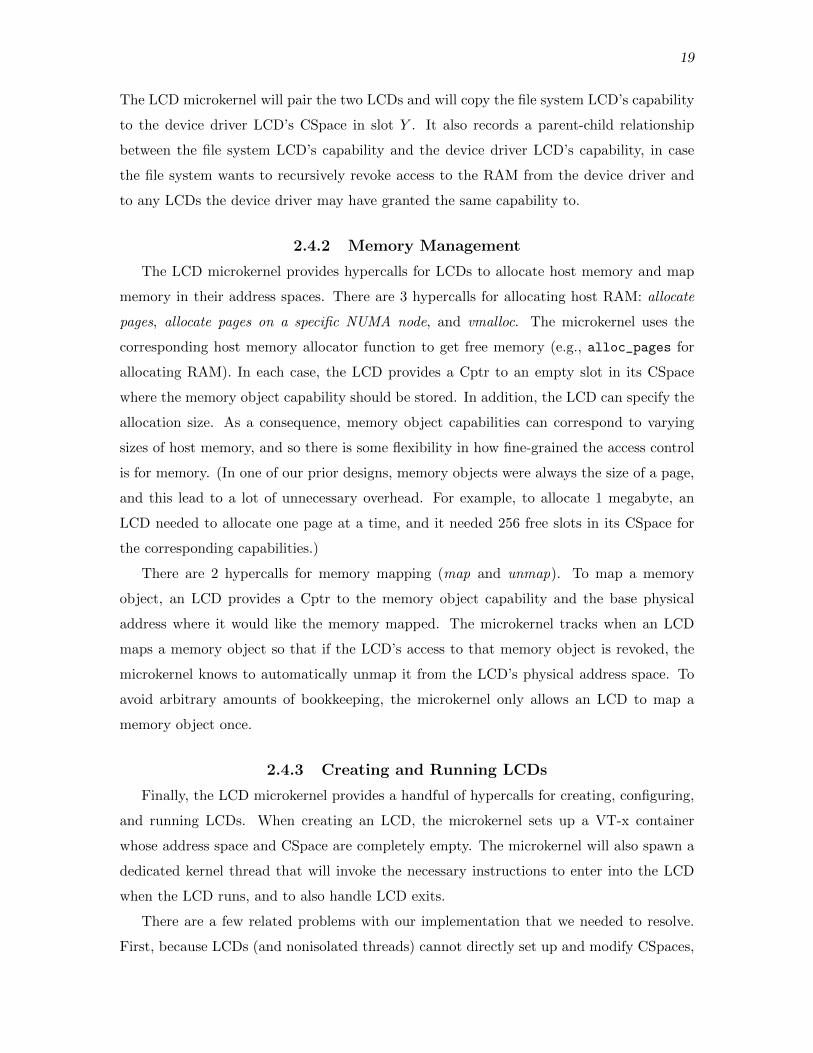
2.4.2 Memory Management
The LCD microkernel provides hypercalls for LCDs to allocate host memory and map
memory in their address spaces. There are 3 hypercalls for allocating host RAM: allocate
pages, allocate pages on a specific NUMA node, and vmalloc. The microkernel uses the
corresponding host memory allocator function to get free memory (e.g., alloc_pages for
allocating RAM). In each case, the LCD provides a Cptr to an empty slot in its CSpace
where the memory object capability should be stored. In addition, the LCD can specify the
allocation size. As a consequence, memory object capabilities can correspond to varying
sizes of host memory, and so there is some flexibility in how fine-grained the access control
is for memory. (In one of our prior designs, memory objects were always the size of a page,
and this lead to a lot of unnecessary overhead. For example, to allocate 1 megabyte, an
LCD needed to allocate one page at a time, and it needed 256 free slots in its CSpace for
the corresponding capabilities.)
There are 2 hypercalls for memory mapping (map and unmap). To map a memory
object, an LCD provides a Cptr to the memory object capability and the base physical
address where it would like the memory mapped. The microkernel tracks when an LCD
maps a memory object so that if the LCD’s access to that memory object is revoked, the
microkernel knows to automatically unmap it from the LCD’s physical address space. To
avoid arbitrary amounts of bookkeeping, the microkernel only allows an LCD to map a
memory object once.
2.4.3 Creating and Running LCDs
Finally, the LCD microkernel provides a handful of hypercalls for creating, configuring,
and running LCDs. When creating an LCD, the microkernel sets up a VT-x container
whose address space and CSpace are completely empty. The microkernel will also spawn a
dedicated kernel thread that will invoke the necessary instructions to enter into the LCD
when the LCD runs, and to also handle LCD exits.
There are a few related problems with our implementation that we needed to resolve.
First, because LCDs (and nonisolated threads) cannot directly set up and modify CSpaces,

20
the LCD microkernel must provide a way for an LCD to grant a capability to the LCD it
is creating. Our solution is that if an LCD has a capability to another LCD, it can grant a
capability to it directly via a hypercall, rather than via synchronous IPC.
Second, we would like to enforce the invariant that an LCD has memory mapped in its
address spaces only if it has a capability to that memory. Rather than rely on the creating
LCD to enforce this invariant, our solution is that the LCD microkernel only provides a
combined grant-and-map function in the interface. It atomically maps the memory in the
LCD’s address space while also carrying out a capability grant from the creating LCD to
the new LCD.
Third, the LCD microkernel relies on the UTCB of an LCD being valid as it carries out
a synchronous IPC transaction (i.e., the UTCB memory should not be return to the host
while the microkernel is using it). However, the UTCB needs to be mapped in the LCD’s
address space, so the invariant above would stipulate that the LCD should have a capability
to the UTCB memory. But rather than attempt to enforce the invariant, we leave it as an
exception.

CHAPTER 3
THE LIBLCD INTERFACE, LIBLCD, AND
KLIBLCD
3.1 Overview
This chapter describes the LIBLCD interface; liblcd, the library kernel that runs inside
an LCD alongside isolated code and provides an implementation of the LIBLCD interface;
and kliblcd, a small module of code that provides an implementation of the LIBLCD
interface to nonisolated threads. Each is described in turn in the sections below.
3.2 The LIBLCD Interface
The LCD microkernel interface is missing useful utilities that LCDs and nonisolated
code need. For example, we want to load kernel modules inside LCDs, but the microkernel
interface only provides low level functions for creating an LCD and setting up its address
space. As another example, the code inside the LCD needs to have memory management
facilities for tracking free regions in its physical address space, setting up slab allocators,
and so on.
To handle these needs, as well as others, we designed the LIBLCD interface, shown
in Figure 1.6. This interface is implemented by liblcd and kliblcd and provides code
with a common environment for interacting with the microkernel and carrying out typical
operations. It provides a more friendly, C-level interface on top of the lower level microkernel
interface. Rather than list the functions, I will describe the more interesting parts of the
interface and how they are implemented in liblcd and kliblcd. Some of the LIBLCD interface
functions are just simple wrappers on top of the lower level microkernel interface.
We attempted to make the semantics of each function in the LIBLCD interface the same,
regardless of whether the code is running inside an LCD or not, but for some functions this
was not possible. For example, the LIBLCD interface includes functions for spawning
nonisolated threads in LCD mode. Isolated code inside LCDs cannot spawn nonisolated
threads, so those functions are no-ops in the liblcd implementation.

22
3.2.1 Environment Initialization
Before using any functions provided by liblcd or kliblcd, code should execute lcd_enter.
This gives the environment a chance to initialize itself. This function was motivated by
CAP_ENTER from Capsicum [40]. When finished using liblcd or kliblcd, code should execute
lcd_exit. The semantics of lcd_exit differs between the two implementations: When
isolated code calls lcd_exit in liblcd, it never returns, similar to exit in user-level. When
nonisolated code calls lcd_exit in kliblcd, it does return. Further details are described in
the respective implementations.
3.2.2 Loading Kernel Modules into LCDs
The LIBLCD interface includes functions for loading a kernel module from disk into
an LCD. The caller provides the module name and the directory (on the host), and the
kernel module is loaded into a fresh LCD. Only kliblcd provides an implementation for
these functions, so only nonisolated threads have the ability to set up LCDs with kernel
modules.
The kliblcd implementation configures the LCD’s address spaces spaces as shown in
Figure 3.1. Recall from Section 2.1 that LCDs always begin running in 64-bit mode. Each
region is described below.
• Miscellaneous Region. The LCD’s UTCB for synchronous IPC, guest virtual page
tables, and bootstrap memory is mapped in a 1 GB region (a large part of this region
is empty on entry). The bootstrap memory is used to pass boot information to the
LCD that it can use as it initializes itself. For example, the creator of the LCD may
insert capabilities into the LCD’s CSpace for synchronous IPC endpoints, memory
objects, and so on, that the LCD needs, and the creator stores the corresponding
Cptrs where those capabilities are stored in the bootstrap memory.
• Stack Region. The kliblcd implementation allocates a handful of pages for an initial
stack and maps it in the stack region (so a large part of this region is empty on entry).
• Heap Region. This is used by the liblcd page allocator, described below. On LCD
entry, this region is empty.
• RAM Map Region. This is used by liblcd to map arbitrary RAM memory objects,
similar to the kmap facility in the Linux kernel. On LCD entry, this region is empty.
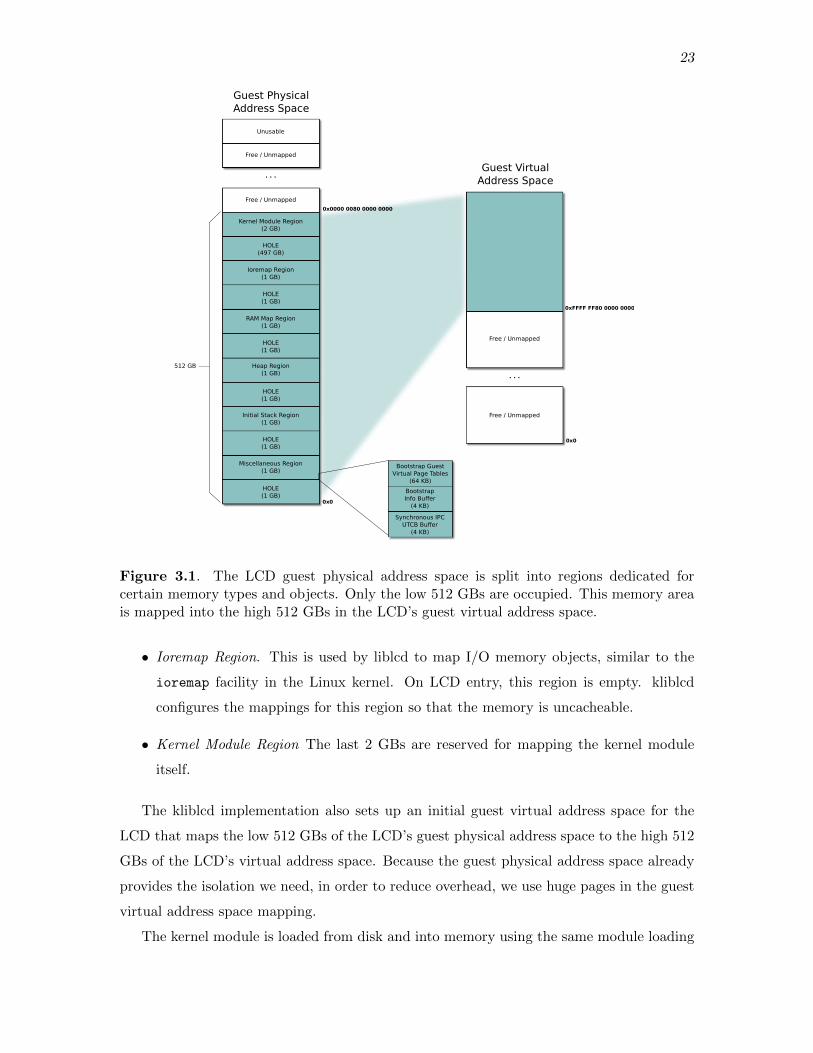
23
HOLE(1 GB)
Miscellaneous Region(1 GB)
HOLE(1 GB)
Initial Stack Region(1 GB)
HOLE(1 GB)
Heap Region(1 GB)
HOLE(1 GB)
RAM Map Region(1 GB)
HOLE(1 GB)
Ioremap Region(1 GB)
HOLE(497 GB)
Kernel Module Region(2 GB)
. . .
Unusable
Synchronous IPC UTCB Buffer
(4 KB)
BootstrapInfo Buffer
(4 KB)
Bootstrap Guest Virtual Page Tables
(64 KB)
Free / Unmapped
Free / Unmapped
512 GB
0x0
0x0000 0080 0000 0000
Free / Unmapped
Free / Unmapped
. . .
0x0
0xFFFF FF80 0000 0000
Guest Physical Address Space
Guest VirtualAddress Space
Figure 3.1. The LCD guest physical address space is split into regions dedicated forcertain memory types and objects. Only the low 512 GBs are occupied. This memory areais mapped into the high 512 GBs in the LCD’s guest virtual address space.
• Ioremap Region. This is used by liblcd to map I/O memory objects, similar to the
ioremap facility in the Linux kernel. On LCD entry, this region is empty. kliblcd
configures the mappings for this region so that the memory is uncacheable.
• Kernel Module Region The last 2 GBs are reserved for mapping the kernel module
itself.
The kliblcd implementation also sets up an initial guest virtual address space for the
LCD that maps the low 512 GBs of the LCD’s guest physical address space to the high 512
GBs of the LCD’s virtual address space. Because the guest physical address space already
provides the isolation we need, in order to reduce overhead, we use huge pages in the guest
virtual address space mapping.
The kernel module is loaded from disk and into memory using the same module loading

24
process, but with some modifications to prevent the kernel module’s initialization routine
from being invoked (we want to run it inside the LCD, not in the nonisolated host). kliblcd
then duplicates the RAM memory that contains the kernel module image (the .ko), and
unloads the original kernel module from the host. The duplicate is what is loaded inside
the LCD. This is done for the following reason. The module loader uses some metadata
that is embedded in the module image (the struct module, symbol tables, and so on), and
it wouldn’t be safe for the host module loader and the LCD to have access to the same
memory (the LCD could corrupt the metadata and confuse the module loader–an integral
part of the host).
On the x86_64 platform, the kernel module is loaded and linked for a spot in the upper 2
GB region of the host virtual address space. In order to avoid relocating the kernel module
for a different address range, we have arranged for the kernel module to be mapped in the
LCD at the same address it was loaded in the host. The LCD begins execution at the
module’s initialization routine (module_init). This is why the upper 2 GBs of the guest
virtual address space are reserved for the kernel module mapping. (We considered patching
the host module loader so that the ELF relocations applied to the kernel module were for
a different base address, but it didn’t seem worth the hassle.)
3.2.3 Memory Management
There are five sets of functions in the LIBLCD interface related to memory management.
First, there are higher-level C functions that are simple wrappers around the lower level
microkernel page allocation functions, described in 2.4.2. These functions return a Cptr to
the allocated memory object. Second, there are more user-friendly functions for allocating
memory that return a pointer to mapped memory (the first set of functions just return a
capability to the memory, and the caller is responsible for mapping it somewhere, if they
wish). Third, there is a set of functions for mapping and unmapping RAM and device
memory. To map memory, the caller provides the Cptr and size of the memory object, and
these functions return the address where the memory object was mapped (each function
will find a free place in the caller’s address space to map the memory object).
Fourth, there are functions for translating memory addresses to memory object Cptrs.
The need for these functions arises in the following scenario. An LCD may have an arbitrary
pointer to some memory in its address space, and it may want to share the memory. Because
we enforce the invariant that an LCD must have a capability to all of the memory inside
its address space (except the UTCB), we know that the memory belongs to some larger
memory object that has been mapped there. These functions take an arbitrary memory

25
address and return three things: the Cptr to the memory object that contains the memory
address, the size of the memory object, and the offset of the address into the memory object.
Finally, there are functions for “volunteering” host memory into the microkernel’s ca-
pability system. They are motivated by the following problem. Nonisolated code can gain
access to host resources, like RAM and I/O memory, without involving the LCD microkernel.
For example, a nonisolated thread can allocate host memory via the nonisolated kernel’s
page allocator. However, the nonisolated code may want to share these host resources
with an LCD. Since we want nonisolated code to use the same explicit, capability grant
mechanism to share resources with LCDs, nonisolated code needs to be able to introduce
the host resource to the LCD microkernel and create a capability for it. We term this
process “volunteering” the host resource. (Internally, the LCD microkernel uses a sparse
tree to track what regions of host memory are currently tracked in the capability access
control system.)
3.2.4 Resource Trees
A resource tree is the data structure used by liblcd and kliblcd for translating memory
addresses to Cptrs (“address-to-Cptr translation”). While it is technically part of the
LIBLCD interface, it is unlikely code outside of liblcd and kliblcd will use it directly.
Resource trees are binary search trees, in which each node is a (start, last, cptr) triple,
where start is the start address of the memory object, last is the last address within the
memory object, and cptr points to the memory object capability in the owner’s CSpace.
Each triple in a resource tree is unique and memory address ranges are nonoverlapping.
(This is why we do not need to use a more general interval tree. The nodes can just be
sorted by starting address.) See Figure 3.2 for an example. Given an address, the lookup
algorithm uses the resource tree to identify the interval that contains it. The algorithm then
returns the corresponding cptr, the size of the memory object that contains the address,
and the offset of the address into the memory object.
In one of our prior implementations for liblcd, we used a giant array of Cptrs for address-
to-Cptr translation, in which the ith element of the array was nonzero if there was a page
mapped at offset 4096 × i (our prior implementation only allowed for single-page-sized
memory objects). This array was only maintained for the heap region, so address-to-Cptr
translation was only possible in this region. This clearly leads to a lot of overhead, and it is
even less realistic for address-to-Cptr translation in the nonisolated environment, in which
there is a huge amount of memory, but only a sparse amount is inside a thread’s CSpace.

26
ioremapRegion
[3, 7]
[10, 19] [94, 96]
[50, 70]
Resource TreeLCD Guest Physical
Address Space
RAM MapRegion
HeapRegion
KernelModule
Cptr to memorycapability
Figure 3.2. The LCD has 4 memory objects mapped in its address space (shown indifferent colors), in the corresponding memory regions for their type (shown in light green).The address ranges where each memory object is mapped along with the cptr for the memoryobject are stored in a resource tree (color coded). For example, the blue memory object ismapped at address range [10, 19] and has a corresponding node in the resource tree.
3.2.5 Generalized Buddy Allocator
3.2.5.1 Overview
The generalized buddy allocator (GBA) is a data structure for tracking page alloca-
tions in a fixed-size address space region. Like resource trees, while technically a part of
the LIBLCD interface, the GBA is only used internally in liblcd. We originally used a
bitmap, first-fit algorithm in the liblcd memory management implementation, but this has
well-known inefficiencies we would like to avoid. The GBA is intended to be used in the
implementations of higher-level allocators (they are the “GBA user”/“GBA creator”), like
the heap and ioremap allocators (see 3.3).
We designed the generalized buddy allocator (GBA) with two goals in mind. First, it
should provide a way to do finer-grained allocations from large allocations obtained from
the microkernel. Second, the allocator metadata should be kept as small as possible, and
it shouldn’t be part of the kernel module image (e.g., in .bss or .data), in order to keep
the image small.
3.2.5.2 Design
The design follows the regular buddy allocator algorithm found in Linux, but with the
following differences. First, numerous instances of the GBA can be created, with different
configurations. Each configuration specifies

27
• The memory region order, in terms of pages (i.e., the memory region is 2x pages for
some x).
• The minimum and maximum allocation order, in terms of pages. For example, a
minimum order of 2 and maximum order of 5 means the minimum allocation size is 4
pages, and the maximum allocation size is 32 pages.
• How metadata is to be allocated, via callbacks, and whether it should be embedded
in the memory region itself.
• How backing memory should be sucked in, via callbacks (this part of the configuration
is optional).
Second, unlike Linux, the GBA minimum allocation size can be configured to be bigger
than a single page, and the amount of metadata is therefore reduced. Like Linux, the GBA
maintains a structure per minimum allocation unit, in a large array; in Linux, this structure
is struct page, and in the GBA, it is struct lcd_page_block. If the minimum allocation
units are larger, there are fewer elements in this array. But this comes with the cost of more
internal fragmentation, and so there is a trade-off between the amount of metadata and the
amount of internal fragmentation. The GBA user can make that choice. Note that the
GBA does not try to reduce internal fragmentation using migration techniques as in Linux.
Equivalently, there is only one migration type in the GBA: no migration.
Third, the creator of a GBA instance specifies how the metadata is allocated using a
callback. The GBA code computes the size of the metadata, given the other parameters,
and invokes the callback. The creator is then free to allocate the metadata in any way they
want. If desired, the metadata can be mapped in the beginning of the memory region itself
(the creator notifies the GBA code of their intent to do so, so that the GBA can properly
initialize itself and mark that part of the memory region as occupied). As described in
3.3, this is used in the liblcd heap so that there is no footprint outside of the heap region.
The GBA code ensures the memory region is big enough to accommodate the metadata.
Note that the metadata should not be embedded in an uncacheable region (like the ioremap
region). The layout of the metadata is shown in Figure 3.3.
Once a GBA instance has been created, it can be used to do allocations within the min-
imum and maximum allocation size. Like the page allocator interface in the Linux kernel, a
GBA allocation returns the struct lcd_page_block for the first minimum allocation unit
in the allocation. In addition, there are functions for translating a struct lcd_page_block
to an offset into the memory region, and back. Note that the GBA is not aware of the base

28
struct lcd_page_allocator { ... struct list_head *free_lists; ... ... struct lcd_page_block *pb_array; ...}
PADDING
min_order free list
min_order + 1 free list
...
max_order free list
PADDING
struct lcd_page_block(for first 2min_order pages)
struct lcd_page_block(for next 2min_order pages)
...
struct lcd_page_block(for last 2min_order pages)
first 2min_order pages
next 2min_order pages
last 2min_order pages
...
Metadata
Memory Region
Figure 3.3. The metadata for an instance of the generalized buddy allocator is shown.The memory region for which the allocator is being used is on the right. The metadataconsists of three parts: a structure, free lists, and an array of struct lcd page blocks. Eachstruct lcd page block corresponds to a chunk of memory of size 2min order pages.
address of the memory region it is tracking. The GBA user is responsible for translating
absolute addresses to offsets into the memory region the GBA is tracking, and back. Also,
the GBA creator is responsible for choosing a memory region base address so that it is
aligned for the maximum allocation unit.
3.2.5.3 Demand Paging
Finally, the GBA provides a means for demand paging on the maximum allocation unit
boundaries. To use this feature, the GBA creator provides nonnull callbacks that specify
how backing memory should be brought in. When the GBA allocates from a maximum
allocation unit (either the whole thing or some subset of it), it invokes the “allocate and
map” callback. The GBA creator should then back the memory region covered by the
maximum allocation unit with memory (e.g., RAM). On the other hand, when the GBA
has recovered a maximum allocation unit from coalescing free blocks, it invokes the “free
and unmap” callback. The GBA creator can then unmap and possibly free the memory
29
associated with this region (e.g., return the RAM to the microkernel).
It is worthwhile to consider how this compares with a balloon driver [39]. The fol-
lowing briefly describes how a balloon driver works. An administrator may configure a
virtual machine so that the maximum RAM it will ever be allotted is 8 GBs. But the
administrator may start the virtual machine with only 1 GBs. The guest operating system
inside the virtual machine boots, thinking that it has access to 8 GBs. At some point in
the boot process, a balloon driver inside the guest allocates the guest physical memory
that corresponds to the unbacked 7 GBs, preventing the page allocator from giving that
memory to some other code that expects real memory to be there. When the administrator
increases the amount of RAM allotted to the virtual machine, the balloon driver will return
the corresponding guest physical pages to the guest page allocator, so that the RAM can
now be used inside the guest.
Comparing the GBA and balloon drivers, the GBA is aware that the memory may
not be backed by real RAM (say), and notifies the GBA user via a callback. Except in
extreme cases, the GBA expects the GBA user to back the corresponding physical address
range. The balloon driver design, on the other hand, is more manual and is triggered by
an administrator, rather than the allocator. The administrator must increase the amount
of RAM allotted to a virtual machine, and the hypervisor notifies the balloon driver inside
the guest. The difference arises, in part, because LCDs are allowed to allocate an arbitrary
amount of memory, and LCDs do relatively finer-grained allocations of host memory. A
virtual machine may be allotted 1 TB of RAM before it even boots, while an LCD may
allocate in chunks of 4 MB at a time. The whole issue of demand paging may go away
if LCDs, like traditional virtual machines, are given a dedicated chunk of RAM from the
beginning (e.g., all of the RAM in a local NUMA node).
3.3 liblcd
3.3.1 Overview
This is a small library kernel that runs inside an LCD. It fulfills a couple of roles.
First, it implements the LIBLCD interface described in the prior section, which includes
a higher-level C interface on top of the lower level VMCALL interface for microkernel
hypercalls. Second, because our primary objective is to run unmodified kernel code inside
an LCD, liblcd also implements common library functions, like memcpy and kmalloc. liblcd
is built as a static library and linked with the kernel module that is to be installed inside
the LCD.

30
liblcd is nearly 13,000 LOC, most of which is code we borrowed from other sources,
including the Linux kernel. As explained further in 3.3.3, only about 2,000 LOC was code
we wrote ourselves. In addition, about 3,000 LOC is shared with kliblcd and the microkernel,
but is built twice–once for liblcd and once for kliblcd. Finally, liblcd includes libcap for
capabilities, libfipc for asynchronous IPC, and libasync, the AC runtime.
3.3.2 Memory Management
liblcd memory management has been designed for the kernel module address space
layout described in 3.2.2. It uses a GBA instance for the heap, RAM map region, and
ioremap region. The heap uses a single page as the minimum allocation unit so that we
can reimplement the Linux page allocator interface on top of the heap, as described in
the next section. RAM map and ioremap allocation units are bigger since more internal
fragmentation can be tolerated in those regions.
liblcd uses a single resource tree to track mapped memory objects and their correspond-
ing Cptrs. This tree is updated every time a memory object is mapped or unmapped from
the LCD’s guest physical address space. Only one tree is required because all memory
objects are contiguous in the LCD’s guest physical address space (this is not true for
nonisolated code).
3.3.3 Providing Linux Functions and Global Variables
As the next chapter describes, for each kernel module dependency–unresolved functions,
global variables, and so on–we must choose how to resolve it. In some cases, it makes sense
to resolve it by redefining the function or global variable inside liblcd. For example, since the
LCD is single threaded and does not handle interrupts, we can redefine locking operations
to be no-ops. Other functions like alloc_pages, part of the Linux kernel’s page allocator
interface, can be redefined using LIBLCD interface functions.
But other functions are impossible to handle with a trivial stub definition or to rewrite
from scratch. Instead, we make a copy of the Linux source code that contains them, and
make them a part of liblcd. This can introduce further dependencies, however, for which
the same kind of analysis must be applied to each. It is helpful to repeatedly use the nm
commandline tool to track outstanding dependencies while carrying out this analysis. For
example, rather than write our own slab allocator, we moved a duplicate of the Linux SLAB
allocator into liblcd. This was feasible because the SLAB allocator only has a handful of
dependencies on the buddy allocator that we could fulfill with liblcd’s page allocator (the

31
heap), and the remaining dependencies were easy to elide or quickly fix. This is also the
approach we used for various library functions like memcpy.
As a result of this work, we realized that liblcd is slowly turning into a library kernel, but
it is being built in an additive way. We are aware of other projects that make it possible to
build Linux as a library kernel, and we think these library kernels will be useful in running
LCDs [5].
3.4 kliblcd
3.4.1 Overview
This is the nonisolated implementation of the LIBLCD interface, and is therefore the
interface that nonisolated threads use to interact with the LCD microkernel. While kliblcd
is conceptually separate from the LCD microkernel, it is compiled as part of the same kernel
module, and it uses internal function calls (as opposed to the VMCALLs for LCDs) to call
into the microkernel. In addition, unlike liblcd, since nonisolated threads have access to
the functions in the host kernel, it is not necessary for kliblcd to provide implementations
of memcpy, kmalloc, and so on. kliblcd is nearly 5,000 LOC, though as mentioned above,
about 3,000 LOC is shared with liblcd. Like liblcd, kliblcd includes libcap, libfipc, and
libasync.
3.4.2 Memory Management
kliblcd memory management is less complicated than in liblcd because host physical
memory is directly accessible from the nonisolated environment (there is no separate physi-
cal address space to be managed). Wherever guest physical mapping was required in liblcd,
kliblcd can simply return host physical addresses directly. In addition, mapping RAM in a
nonisolated thread’s virtual address space is also easy: On the x86_64 platform, all RAM
is already mapped, and so kliblcd can return host virtual addresses directly. Note that
ioremap functions in the LIBLCD interface are not implemented in kliblcd.
Despite these simplifications, nonisolated code still uses these memory management-
related functions in the LIBLCD interface for a couple of reasons. First, nonisolated code
may be granted a capability to RAM, and it may only know the Cptr to its capability
and not the address of the RAM. By invoking the memory mapping functions in the
LIBLCD interface, the nonisolated code is able to obtain the address of the RAM (even
though no actual mapping is done). Second, the memory management functions provide
kliblcd a chance to update the resource trees required for address-to-Cptr translation in the
nonisolated environment.

32
Unlike the isolated environment, memory objects in the nonisolated environment may
not be physically contiguous. For example, memory obtained from vmalloc is contiguous
in the host’s virtual address space, but not necessarily in RAM. kliblcd therefore maintains
two resource trees: one for physically contiguous memory, and another for physically
noncontiguous memory (vmalloc memory). These trees are maintained per thread because
each nonisolated thread has its own CSpace, and the Cptrs returned from address-to-Cptr
translation need to be valid for that CSpace.
When a nonisolated thread invokes a memory mapping function in the LIBLCD inter-
face, kliblcd creates a new node in the appropriate tree for the memory object. At some point
later, the nonisolated thread can invoke the address-to-Cptr related functions, and kliblcd
will query the appropriate tree. For virtual addresses, kliblcd queries the noncontiguous
tree first. If a containing memory object is not found, kliblcd translates the virtual address
to the corresponding physical address, and uses the contiguous tree. kliblcd makes every
effort to be accurate, but it is possible for nonisolated code to use the LIBLCD interface
improperly and confuse the kliblcd internals. We do not guard against this possibility since
nonisolated code is trusted.

CHAPTER 4
DECOMPOSITION TECHNIQUES
4.1 Overview
The prior chapters described the microkernel and overall architecture, including some of
the key mechanisms and components for running and interacting with isolated code. This
chapter presents the techniques we used to systematically break code apart. Our objective
is to run unmodified Linux code that was written for a shared memory environment on top
of the shared nothing LCD architecture.
This is not an easy task. Linux kernel modules consist of thousands of lines of code
that interact with the core kernel in complicated patterns–function calls, passing shared
objects, synchronization, sharing global variables, and so on. But we noticed the same
interaction patterns appearing throughout the kernel, and this led us to believe it might
be feasible to classify patterns and develop general strategies for emulating them in the
LCD architecture. For example, kernel modules typically implement an object-oriented
interface to export their functionality to the core kernel (e.g., file systems implement the
VFS interface), and we investigated if such interfaces could be easily translated into a
message passing protocol.
Other kernel refactoring and decomposition work, like the Rump Kernels project, seemed
to provide further evidence that decomposing Linux would be feasible [18]. In the Rump
Kernels project, the NetBSD kernel was refactored into a base component and “orthogonal
factions”–dev, net, and vfs–that are independent of each other. While components in a
rump kernel still interact through shared memory interfaces, we found it compelling that a
monolithic kernel could be systematically refactored into components.
4.2 Lightweight Interposition Layers
As described in 1.2.6, we introduced interposition layers in two places: One layer is linked
with the isolated kernel module and runs inside the LCD, while the other layer is installed
in the nonisolated, core kernel. The interposition layer for an LCD consists of liblcd, built

34
as a static library, and glue code, built as a collection of object files; these are built using
the kernel’s build system and linked with the kernel module that is to be isolated. The
interposition layer for the nonisolated side is built and installed as a regular kernel module.
Together, the interposition layers resolve all dependencies so that the original code works
seamlessly in this new architecture.
It is worth comparing these interposition layers to other systems like the Network Filesys-
tem (NFS) protocol, the Filesystem in Userspace (FUSE) interface, Filesystem Virtual
Appliances (FSVA), and network block device protocols like iSCSI and NBD [35, 38, 1].
These are client-server systems (in FUSE, the client is the kernel, and the server is the
user-level FUSE file system). The client typically has a module installed in its kernel
that translates local operations into protocol messages transmitted to the server, while the
server runs a user-level application that receives and processes the protocol messages from
the client. These client and server components that transparently translate local operations
to remote ones can be seen as similar to the glue code in the LCD architecture. On the
other hand, making the comparison in the other direction, in the LCD architecture, the
nonisolated kernel could be considered the client, while the isolated LCD is the server (e.g.,
the LCD contains a filesystem and acts as a file server).
However, our approach in building the interposition layers and “protocol” is different
from these other systems. Rather than develop a new protocol from scratch, we system-
atically go through each shared memory interaction pattern that crosses an interface and
translate it to an equivalent pattern in the LCD architecture. We effectively translate the
implied protocol in a shared memory interface directly into a message passing protocol that
completely preserves the original semantics. As mentioned in the overview, our hypothesis
is that there are only a small number of shared memory interaction patterns, and we can
develop general techniques that make it easy to break the code apart. Further, we contend
that this is easier than designing a new protocol and writing ‘smarter’ glue code (like the
NFS client).
4.3 Decomposing Linux Inside the Source Tree
One of our objectives is to decompose Linux within the source tree, so that decomposed
code can evolve along with the rest of the kernel. While our current build system requires
duplicating the source files for the kernel module to be isolated, we did develop techniques
for building all code–nonisolated and isolated–at once and with the same headers.
All LCD-related source code and headers–the microkernel, liblcd library kernel, kliblcd,
and so on–reside in the lcd-domains directory in the Linux source tree, but are built as
35
external modules. This is for practical reasons only (it is easier to repeatedly rebuild a
set of external modules). Furthermore, we duplicate the source files for the kernel module
that is to be isolated into a separate directory inside lcd-domains, for practical reasons
as well. Alternatively, minimal modifications to the original kernel module source files and
build system files could easily be done so that the kernel module is built for the LCD
environment and linked with the interposition layer (liblcd and the glue code).
Rather than rewrite new headers for the same kernel functions and data structures that
the interposition layers provide, all code is compiled with the original Linux headers. For
example, liblcd provides an implementation of kmalloc; rather than duplicate or write our
own header that defines the interface for kmalloc, including all of the constants, we reuse
the slab-related headers. We made this choice because Linux headers are large and complex
with hundreds of build system macros and further includes, and it would be tedious and
error prone to duplicate these headers or rewrite them from scratch. In addition, kernel
modules that we intend to isolate are made up of source code that expects a lot of these
headers and build system macros to be available, and we would like to touch the source
code as little as possible.
But we cannot reuse the Linux headers directly. The nonisolated code build configura-
tion may not correspond exactly to the execution environment inside the LCD. For example,
LCDs are currently single-threaded (single core), and so we would like to eliminate a lot
of the SMP-related configuration options. In addition, even some parts of the nonisolated
code configuration may be LCD friendly, but may require bringing a lot of unwanted code
into the LCD to fulfill additional dependencies.
Our solution is to two fold. First, we created a special “prehook” header to be included
in all of the source files that are compiled for LCDs (kernel module, glue, and liblcd source
files). This header undefines unwanted configuration options before all of the remaining
headers and code in a source file are processed, effectively changing the build configuration
for that particular file. This is error prone and sensitive to the nonisolated kernel build
configuration, and it can introduce some very subtle, nasty bugs. We may explore an
alternative approach in the future.
Second, we created a special “posthook” header that redefines problematic C macros
and other constructs. This header is included after all other headers in a C source file that is
to be built for an LCD. For example, in the posthook header, we redefine Linux’s BUG macro
so that it does not trigger an undefined opcode exception. This header can also be used to
elide entire function calls, making the remaining decomposition techniques described below
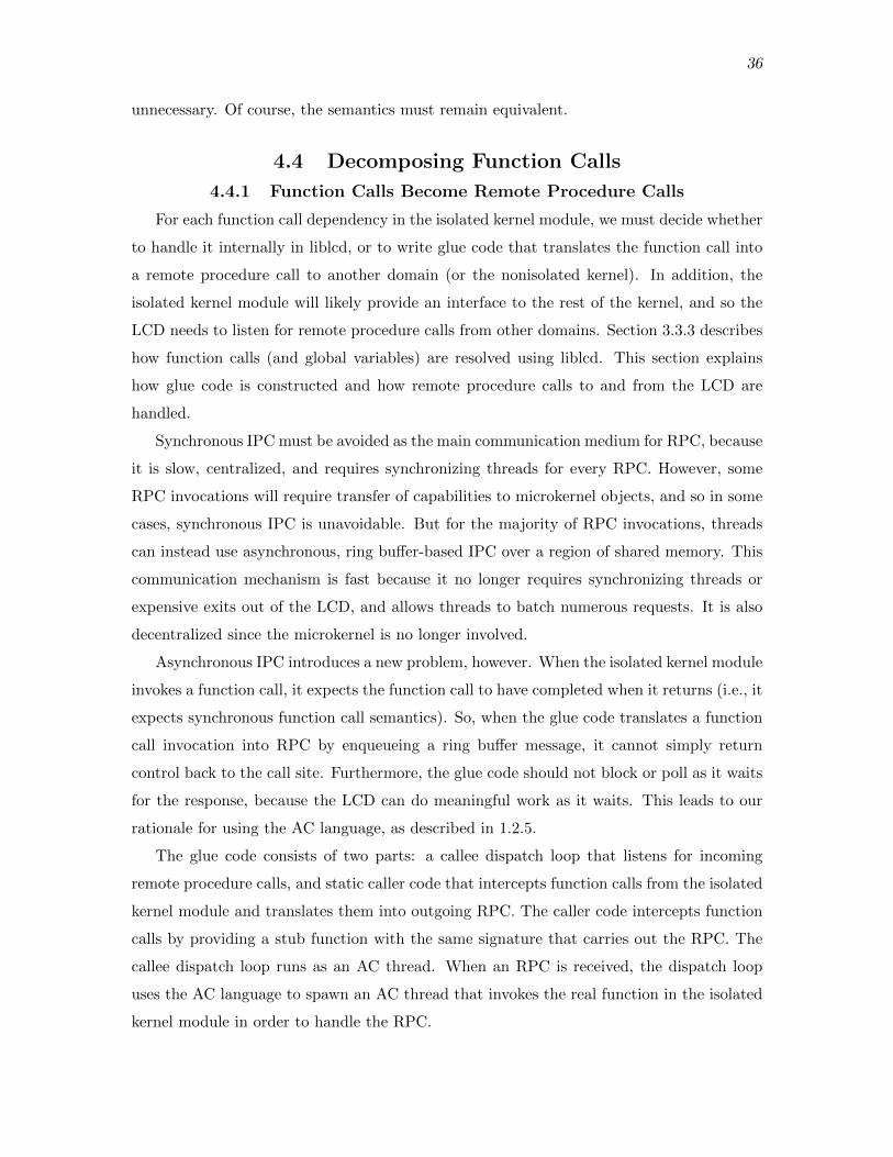
36
unnecessary. Of course, the semantics must remain equivalent.
4.4 Decomposing Function Calls
4.4.1 Function Calls Become Remote Procedure Calls
For each function call dependency in the isolated kernel module, we must decide whether
to handle it internally in liblcd, or to write glue code that translates the function call into
a remote procedure call to another domain (or the nonisolated kernel). In addition, the
isolated kernel module will likely provide an interface to the rest of the kernel, and so the
LCD needs to listen for remote procedure calls from other domains. Section 3.3.3 describes
how function calls (and global variables) are resolved using liblcd. This section explains
how glue code is constructed and how remote procedure calls to and from the LCD are
handled.
Synchronous IPC must be avoided as the main communication medium for RPC, because
it is slow, centralized, and requires synchronizing threads for every RPC. However, some
RPC invocations will require transfer of capabilities to microkernel objects, and so in some
cases, synchronous IPC is unavoidable. But for the majority of RPC invocations, threads
can instead use asynchronous, ring buffer-based IPC over a region of shared memory. This
communication mechanism is fast because it no longer requires synchronizing threads or
expensive exits out of the LCD, and allows threads to batch numerous requests. It is also
decentralized since the microkernel is no longer involved.
Asynchronous IPC introduces a new problem, however. When the isolated kernel module
invokes a function call, it expects the function call to have completed when it returns (i.e., it
expects synchronous function call semantics). So, when the glue code translates a function
call invocation into RPC by enqueueing a ring buffer message, it cannot simply return
control back to the call site. Furthermore, the glue code should not block or poll as it waits
for the response, because the LCD can do meaningful work as it waits. This leads to our
rationale for using the AC language, as described in 1.2.5.
The glue code consists of two parts: a callee dispatch loop that listens for incoming
remote procedure calls, and static caller code that intercepts function calls from the isolated
kernel module and translates them into outgoing RPC. The caller code intercepts function
calls by providing a stub function with the same signature that carries out the RPC. The
callee dispatch loop runs as an AC thread. When an RPC is received, the dispatch loop
uses the AC language to spawn an AC thread that invokes the real function in the isolated
kernel module in order to handle the RPC.
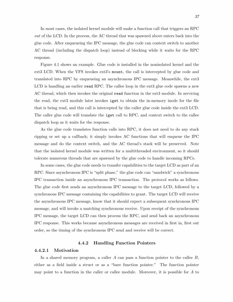
37
In most cases, the isolated kernel module will make a function call that triggers an RPC
out of the LCD. In the process, the AC thread that was spawned above enters back into the
glue code. After enqueueing the IPC message, the glue code can context switch to another
AC thread (including the dispatch loop) instead of blocking while it waits for the RPC
response.
Figure 4.1 shows an example. Glue code is installed in the nonisolated kernel and the
ext3 LCD. When the VFS invokes ext3’s mount, the call is intercepted by glue code and
translated into RPC by enqueueing an asynchronous IPC message. Meanwhile, the ext3
LCD is handling an earlier read RPC. The callee loop in the ext3 glue code spawns a new
AC thread, which then invokes the original read function in the ext3 module. In servicing
the read, the ext3 module later invokes iget to obtain the in-memory inode for the file
that is being read, and this call is intercepted by the caller glue code inside the ext3 LCD.
The caller glue code will translate the iget call to RPC, and context switch to the callee
dispatch loop as it waits for the response.
As the glue code translates function calls into RPC, it does not need to do any stack
ripping or set up a callback; it simply invokes AC functions that will enqueue the IPC
message and do the context switch, and the AC thread’s stack will be preserved. Note
that the isolated kernel module was written for a multithreaded environment, so it should
tolerate numerous threads that are spawned by the glue code to handle incoming RPCs.
In some cases, the glue code needs to transfer capabilities to the target LCD as part of an
RPC. Since asynchronous IPC is “split phase,” the glue code can “sandwich” a synchronous
IPC transaction inside an asynchronous IPC transaction. The protocol works as follows.
The glue code first sends an asynchronous IPC message to the target LCD, followed by a
synchronous IPC message containing the capabilities to grant. The target LCD will receive
the asynchronous IPC message, know that it should expect a subsequent synchronous IPC
message, and will invoke a matching synchronous receive. Upon receipt of the synchronous
IPC message, the target LCD can then process the RPC, and send back an asynchronous
IPC response. This works because asynchronous messages are received in first in, first out
order, so the timing of the synchronous IPC send and receive will be correct.
4.4.2 Handling Function Pointers
4.4.2.1 Motivation
In a shared memory program, a caller A can pass a function pointer to the callee B,
either as a field inside a struct or as a “bare function pointer.” The function pointer
may point to a function in the caller or callee module. Moreover, it is possible for A to

38
AC Threads
ext3
calleeloop
callercode
Linux
calleeloopcaller
code
VFS
mount
libfipcAsync IPC
read
Glue
iget
Figure 4.1. Function calls to and from the VFS and ext3 module are transparentlytranslated into RPC.
receive multiple instances of the same function pointer. For example, file systems in the
Linux kernel register an object-oriented interface with the VFS by passing it a structure of
function pointers. Since more than one file system can register with the VFS, there can be
more than one instance of these function pointers.
In the LCD architecture, like regular function calls, when B later invokes the function
via the pointer, B’s glue code will intercept the call and translate it into RPC that targets
A. This is done for all function pointers that are passed from A to B, even those that point
to functions that are not implemented by A. In this case, A will receive the RPC for the
function pointer from B, and A’s callee glue code will invoke the original function pointer,
which, if not defined in A’s module, will be caught by the caller glue code and translated
into RPC to the domain that does implement the function.
At a minimum, when B’s glue code intercepts the function pointer call, it needs to know
who it should send the RPC to. However, other domains in addition to A may have passed
a function pointer that could be used in the same calling context, and so the target LCD
is not known statically as is the case for regular functions. If we follow the same approach
and use a single stub function to intercept the function pointer call (passing a pointer to the
stub function in lieu of the real pointer when A invokes a RPC to B), it will be impossible
for the glue to determine which LCD to send a RPC to.
There are a few natural approaches that first come to mind. First, like other systems
such as NFS, every isolated module could have a “proxy” installed in the nonisolated kernel
that implements the interface of function pointers. For example, the isolated ext3 module
would have a corresponding ext3 proxy module installed in the nonisolated kernel that
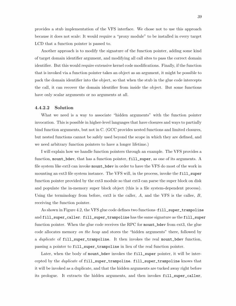
39
provides a stub implementation of the VFS interface. We chose not to use this approach
because it does not scale: It would require a “proxy module” to be installed in every target
LCD that a function pointer is passed to.
Another approach is to modify the signature of the function pointer, adding some kind
of target domain identifier argument, and modifying all call sites to pass the correct domain
identifier. But this would require extensive kernel code modifications. Finally, if the function
that is invoked via a function pointer takes an object as an argument, it might be possible to
pack the domain identifier into the object, so that when the stub in the glue code intercepts
the call, it can recover the domain identifier from inside the object. But some functions
have only scalar arguments or no arguments at all.
4.4.2.2 Solution
What we need is a way to associate “hidden arguments” with the function pointer
invocation. This is possible in higher-level languages that have closures and ways to partially
bind function arguments, but not in C. (GCC provides nested functions and limited closures,
but nested functions cannot be safely used beyond the scope in which they are defined, and
we need arbitrary function pointers to have a longer lifetime.)
I will explain how we handle function pointers through an example. The VFS provides a
function, mount_bdev, that has a function pointer, fill_super, as one of its arguments. A
file system like ext3 can invoke mount_bdev in order to have the VFS do most of the work in
mounting an ext3 file system instance. The VFS will, in the process, invoke the fill_super
function pointer provided by the ext3 module so that ext3 can parse the super block on disk
and populate the in-memory super block object (this is a file system-dependent process).
Using the terminology from before, ext3 is the caller, A, and the VFS is the callee, B,
receiving the function pointer.
As shown in Figure 4.2, the VFS glue code defines two functions–fill_super_trampoline
and fill_super_caller. fill_super_trampoline has the same signature as the fill_super
function pointer. When the glue code receives the RPC for mount_bdev from ext3, the glue
code allocates memory on the heap and stores the “hidden arguments” there, followed by
a duplicate of fill_super_trampoline. It then invokes the real mount_bdev function,
passing a pointer to fill_super_trampoline in lieu of the real function pointer.
Later, when the body of mount_bdev invokes the fill_super pointer, it will be inter-
cepted by the duplicate of fill_super_trampoline. fill_super_trampoline knows that
it will be invoked as a duplicate, and that the hidden arguments are tucked away right before
its prologue. It extracts the hidden arguments, and then invokes fill_super_caller,

40
ext3
VFS
ext3_fill_super
Linux
heap
.text
fill_super_trampoline
fill_super_caller
fill_super_trampoline
hidden args
calleeloop
mount_bdevfill_super
Original trampoline code (never called)
Duplicate trampoline code
Figure 4.2. The VFS glue code sets up a duplicate of a trampoline function along withhidden arguments on the heap so that it can redirect the function pointer invocation to thereal target inside the ext3 module.
passing the arguments that are part of the original fill_super signature along with the
hidden arguments. fill_super_caller then carries out the required RPC, using the hidden
arguments to determine the target LCD.
Our current implementation of this mechanism requires a combination of linker scripts
and assembly, primarily because, to our knowledge, the C compiler does not provide a way
to obtain the address of the first instruction in a function at runtime (function addresses
are treated like global variables). This is needed in order to extract the hidden arguments,
since they are stored right before the first instruction in the function. In addition, since
trampolines are allocated at runtime, some manual analysis is required to determine their
lifetime, so that they are initialized and later deallocated at the right time.
4.4.3 Analyzing Function Calls
Every unresolved function or function pointer needs to be handled while building the
interposition layers, and detailed analysis is required in order to fully preserve the original
semantics. The following sketch provides some guidelines. First, all of the unresolved
functions and function pointers that will result when the code is split apart should be
identified. These can be determined using the following steps:
1. A symbol table tool, like the nm commandline tool, can be used to determine all of the
undefined functions for a kernel module and other object files. These are functions
that are declared as globally accessible in the kernel. (Weak symbols can be manually

41
resolved to determine which definition should be used.) Label this group of functions
as F .
2. For each function that appears as an undefined symbol in F , check if any of its
arguments are function pointers, or a structure that contains function pointers. These
are functions that are passed across domains and may be called from another domain.
Label this group of functions F ′, and let F = F ∪ F ′. Except in extreme cases, the
functions that are passed as function pointers can be determined statically. Note
that these functions will not necessarily appear as undefined symbols, so this step is
necessary.
3. Repeat step 2 until F does not change (some functions passed as pointers may
themselves receive function pointers as arguments).
Next, for each function in F , determine if the domain crossing is necessary. The function
could possibly be redefined in liblcd or the glue code (even to a no-op) while maintaining the
desired level of correctness. If the objective is to only get certain high-level features working,
it may not even be necessary to resolve this dependency (the function is never called). For
complex code, a call graph can be used to determine which functions are required in order
to get a certain feature working (e.g., using the Doxygen documentation tool [7]).
Finally, for those functions in F that require a domain crossing, sketch a graph of the
call dependencies between them (this will likely be a directed acyclic graph). Start writing
glue code for “leaf domain crossings,” and work upward (writing the glue code will require
analyzing data flow, as described below). It is easier to start with leaf domain crossings
because no further domain crossings will happen, and it is easier to reason about. See
Figure 4.3 for an example.
4.5 Handling Shared Objects
4.5.1 Shared Objects are Replicated
By definition, in a shared memory program, two modules can share state between each
other. For example, one module may define a global variable with external linkage that is
directly accessible from the other module, or it may define the global variable with internal
linkage but pass a pointer to it as an argument in a function call to the second module.
Either module may allocate objects on the stack or in the heap and pass pointers to those
objects as function arguments.
In the LCD architecture, the two modules will no longer share a common address space,
but we want to provide the illusion that the code is still operating in a shared memory
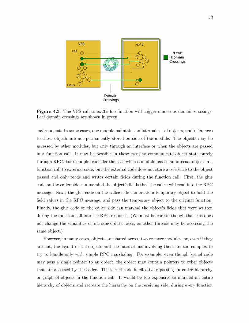
42
ext3
DomainCrossings
VFS
Linux
foo"Leaf"
Domain Crossings
Figure 4.3. The VFS call to ext3’s foo function will trigger numerous domain crossings.Leaf domain crossings are shown in green.
environment. In some cases, one module maintains an internal set of objects, and references
to those objects are not permanently stored outside of the module. The objects may be
accessed by other modules, but only through an interface or when the objects are passed
in a function call. It may be possible in these cases to communicate object state purely
through RPC. For example, consider the case when a module passes an internal object in a
function call to external code, but the external code does not store a reference to the object
passed and only reads and writes certain fields during the function call. First, the glue
code on the caller side can marshal the object’s fields that the callee will read into the RPC
message. Next, the glue code on the callee side can create a temporary object to hold the
field values in the RPC message, and pass the temporary object to the original function.
Finally, the glue code on the callee side can marshal the object’s fields that were written
during the function call into the RPC response. (We must be careful though that this does
not change the semantics or introduce data races, as other threads may be accessing the
same object.)
However, in many cases, objects are shared across two or more modules, or, even if they
are not, the layout of the objects and the interactions involving them are too complex to
try to handle only with simple RPC marshaling. For example, even though kernel code
may pass a single pointer to an object, the object may contain pointers to other objects
that are accessed by the callee. The kernel code is effectively passing an entire hierarchy
or graph of objects in the function call. It would be too expensive to marshal an entire
hierarchy of objects and recreate the hierarchy on the receiving side, during every function

43
call. Figure 4.4 shows a simplified version of an object graph that appears in the VFS and
filesystem-related code. The figure also shows how kernel code uses specific object layouts
for implementing interfaces in C. A generic struct inode is stored right after a filesystem-
specific inode object, and the filesystem code uses pointer arithmetic to move between the
two.
Our conclusion from these observations is that modules need to share state–not through
shared memory, but by some other means. One approach is to maintain a single, global
copy of an object in a central location and provide secure access to it to certain domains.
But centralizing system state could introduce a lot of unnecessary access latency and the
central object repository would need to be trusted by all domains. In addition, domains
would still need to maintain their own private copies of the objects, “snapshots” of the
system state, that are passed to the original kernel code.
This leads to the solution we chose to follow. In our approach, objects that are involved
in stateful interactions are replicated. Each domain maintains its own replica of the system
state, and replicas are synchronized as necessary using RPC. From our experiences looking
at kernel code, we noticed that many objects that are passed across interfaces consist of
two disjoint sets of fields: the first set is primarily used by the file system or device driver
that implements the interface, and the second set is used by the core kernel that uses the
interface. For example, the struct super_block in the Linux VFS interface consists of
nearly 50 fields, but less than half of those fields are used by a file system, including more
complex file systems like XFS. This implies that there is less contention on the fields in such
objects, and consequently less synchronization will be required. In addition, prior work has
also shown that a replicated approach yields better performance in an operating system [2].
Initializing, synchronizing, and tearing down object replicas at the right time requires
some thought, and must be handled on a case-by-case basis. In the original shared memory
code, an object is allocated by a module either statically as a global variable or dynamically
on the stack or heap, and then shared with other modules. In the LCD environment, the
other modules need to be given a replica of the object in lieu of the original when it would
have been shared and accessed by them. Our general approach is to have the glue code
layers manage object replicas. When necessary, the glue code allocates and initializes an
object replica and “piggy backs” on RPC to synchronize the replica with other domains
throughout the replica’s lifetime. It may be necessary to introduce additional IPC exchanges
in order to synchronize replicas at the right time, though we did not encounter any examples.
Note that initializing the object itself may be somewhat complex and requires some manual

44
ext3superblock
dentry
ext3inode
Figure 4.4. The objects used in the VFS interface are connected in a complex graph. Thefigure shows a simplified example. The yellow squares are the generic objects used in theVFS interface, while the blue squares are the filesystem-specific data (ext3 in this case). Apointer to the file object in the figure may be passed as an argument, for example, but thecallee may access many of the other objects in the graph during the function call.
analysis of the code (e.g., for per-CPU objects and data).
4.5.2 Secure Remote References
Domains need a way to securely reference the object replicas in other domains. For
example, when the VFS invokes an operation on an inode, it needs a way to refer to ext3’s
private replica of the inode object. Our solution is to reuse the same capability access
control design found in the LCD microkernel. A Cptr is now used as a remote reference to
an object in another, target domain. The target domain’s glue code maintains a CSpace
that it uses to resolve the Cptr to the private object replica. Capabilities could also be
used for higher-level objects like files, so that in a sense, domains become “microkernels”
for the objects they manage, decentralizing access control. Using capabilities provides a
secure mechanism for remote references because valid references are restricted to only those
objects in a CSpace, and the object lookup algorithm is type safe. Figure 4.5 shows an
example for a pair of replicated objects, a super block and inode. When the VFS glue code
translates an inode operation into RPC, it uses the inode Cptr to refer to ext3’s private
replica.
The figure also presents one of our other techniques. When a glue code stub intercepts a
function call that passes pointers to objects, it needs to translate local pointers into remote
references so that it can set up the RPC. Our solution is to wrap existing objects, or structs,
inside a container struct. The container struct provides fields for the glue code layer to store

45
Linux
VFS
superblock
inodeext3
superblock
inode
ext3
VFS
CSpace
Cptr
Glue
ContainerStruct
Figure 4.5. The VFS and ext3 have their own private replica of the super block and inodeobjects shown. Glue code on both sides maintains a CSpace that is used to translate remotereferences (Cptrs) into local pointers. The objects themselves are wrapped in containerstructs, in which the glue code can store per-object metadata (shown in blue) like remotereferences.
additional metadata, like remote references that refer to the object copies in other domains.
From our experience, embedding metadata around kernel objects has not introduced any
problems. Note that this does require altering some kernel code so that stateful objects are
allocated with a container around them.
4.5.3 Analyzing Shared Objects and Data Flow
All object replicas must be maintained so that the code still works at the desired level
of correctness. This requires careful, manual analysis of the kernel code involved and is not
trivial. Shared objects can percolate into different parts of a module and become accessible
to a wide variety of code, and it can be difficult to determine when the code accesses them.
The following sketch covers some data flow patterns when objects are passed as arguments.
1. Starting with the “leaf level” functions in F from 4.4.3, look for objects passed as
arguments.
2. For each object, determine whether the object should or already has been replicated.
If this is the first time the object is crossing the isolation boundary, object replicas and
remote references should be set up. It is also necessary to identify when the object
replicas should be torn down. Note that it may be necessary to set up object replicas
even when the original shared memory interaction does not appear stateful, because
the object is passed back and forth across the isolation boundary in a criss crossing
pattern, similar to the pattern shown in Figure 4.3.

46
3. Determine in what RPC messages object replicas should be synchronized, and which
fields. In general, this is difficult to determine and requires manually inspecting code
and deciding when to ship field values in RPC in order to ensure the desired level
of coherence and correctness is achieved. Some objects that are not related to the
function call may even require synchronization. (We are faced with the same issues
that arise in other coherence protocols, like the cache coherence protocol in hardware
and distributed shared memory.)
Figure 4.6 shows an example. As future work, we intend to use Data Structure Analysis
(DSA) to automate some of the analysis for determining which object fields are accessed
and when [20].
4.6 Sharing Strings and Memory Buffers
Strings and arbitrary memory buffers may also be shared through global variables or
pointers passed as arguments. While we could use the same approach as shared objects and
replicate strings and memory buffers (after all, an object is just a typed memory buffer),
buffers are usually a lot larger and it is harder to reason about reads and writes to them
since they are untyped. If buffers are large or shared frequently between two domains,
especially on the data path, it may be worthwhile to set up a region of shared memory
between them. Buffers from the caller can be copied into the shared memory and passed
to the callee, or the caller may be able to allocate memory from the shared region so that
the data transfer is zero-copy.
Buffers can also be shared temporarily for convenience instead of marshaling it into an
RPC message. This can be done to pass strings when performance does not matter. The
following protocol can be used.
1. The caller layer determines the memory object that contains the buffer, and the asso-
ciated capability it has to that object (using the address-to-cptr translation functions
in the LIBLCD interface described in 3.2.4).
2. The caller grants the callee a capability to the memory object, and also provides the
offset and length of the string inside the memory object.
3. The caller grants the callee a capability to the memory object, using synchronous
IPC.
4. The callee maps the memory object in its address space, and uses the offset and length
to recreate the pointer to the string.

47
ext3RPC
VFS
write i->sizewrite i->status
read i->statuswrite i->status
write i->statusread i->size
read i->size
Non-ConcurrentCode Sections
inode inode
status
size
Figure 4.6. The VFS and ext3 filesystem share an inode object. The white blocks arenonconcurrent code sections– they may be critical sections surrounded by a lock, or framesin a call graph that criss crosses back and forth. The fields of the inode that are accessedare shown. The field values are shipped in RPC messages at the right time so that the codeworks properly. Note that the size field value could have been sent in the earlier RPC, butthe VFS doesn’t access this field until later.
Since this technique requires granting a capability, it uses synchronous IPC and is
therefore slow. It can also be too coarse grained if the memory object that contains the
buffer is large. For example, the buffer may only be 12 bytes, but the memory object may
be 4 MBs of RAM from the heap. This technique should be used sparingly.
4.7 Related and Future Work
Writing the glue code described in this section by hand is very tedious and error prone.
We explored using an IDL to describe the high-level shared memory interaction patterns,
and a compiler to translate the IDL into glue code. In addition, there are more shared
memory patterns that we did not develop general techniques for. For example, a caller and
callee may share a global variable and modify it under a lock. We leave such patterns for
future work.

CHAPTER 5
CASE STUDY: ISOLATING PMFS
5.1 Overview
We created small kernel modules in order to exercise individual pieces of the LCD
architecture and decomposition techniques; but in order to truly assess the feasibility of our
design choices, we needed to take an existing nontrivial kernel module and try to isolate it.
To this end, we decided to isolate the Persistent Memory File System (PMFS) developed by
Intel [8]. PMFS consists of a few patches to the core of the Linux kernel and a kernel module
that is approximately 6,000 LOC (our objective is to isolate the kernel module only). PMFS
is an “in memory” file system: All files and directories are stored in nonvolatile memory (or
RAM if persistence is unnecessary) that is directly accessible from the processor.
Like other file systems in Linux, PMFS sits below the Virtual File System (VFS) and
interacts with the VFS through an object-oriented interface with the same name, the VFS
interface. The VFS is the component in the core of the Linux kernel that sits between
applications and individual file systems. See Figure 5.1. The VFS concept and first
implementation was developed back in the 1980s at Sun Microsystems [35].
The VFS fulfills a few roles. First, it is responsible for receiving file system-related system
calls from user-level and carries out various file system-independent tasks, like traversing
directories, sanitizing system call arguments, and checking permissions. Second, it provides
the infrastructure for connecting numerous file systems under one directory tree. Third,
it provides additional generic functions and utilities that file systems can use to carry out
common tasks.
The VFS interface is used by the VFS to communicate with a specific file system for
file system-specific parts of a system call. For example, the VFS calls into a file system
to list entries in a directory since the storage format of directories on disk depends on the
file system. The objects in the VFS interface represent common file system structures, like
inodes, directory entries, and super blocks, and each object type has a set of associated
operations. The interactions between the VFS and a file system relies on having shared
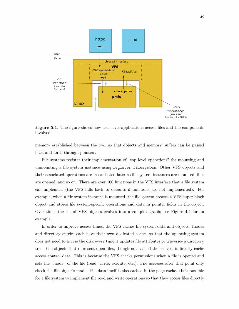
49
httpd sshd
VFS
Syscall Interface
FS-Independent Code
FS Utilities
pmfs
Linux
read
read
check_perms
VFSInterface
(over 100 functions)
Linux"Interface"
(about 100 functions for PMFS)
User
Kernel
Figure 5.1. The figure shows how user-level applications access files and the componentsinvolved.
memory established between the two, so that objects and memory buffers can be passed
back and forth through pointers.
File systems register their implementation of “top level operations” for mounting and
unmounting a file system instance using register_filesystem. Other VFS objects and
their associated operations are instantiated later as file system instances are mounted, files
are opened, and so on. There are over 100 functions in the VFS interface that a file system
can implement (the VFS falls back to defaults if functions are not implemented). For
example, when a file system instance is mounted, the file system creates a VFS super block
object and stores file system-specific operations and data in pointer fields in the object.
Over time, the set of VFS objects evolves into a complex graph; see Figure 4.4 for an
example.
In order to improve access times, the VFS caches file system data and objects. Inodes
and directory entries each have their own dedicated caches so that the operating system
does not need to access the disk every time it updates file attributes or traverses a directory
tree. File objects that represent open files, though not cached themselves, indirectly cache
access control data. This is because the VFS checks permissions when a file is opened and
sets the “mode” of the file (read, write, execute, etc.). File accesses after that point only
check the file object’s mode. File data itself is also cached in the page cache. (It is possible
for a file system to implement file read and write operations so that they access files directly

50
every time, bypassing the page cache. This is what PMFS does.)
One of the important implications of caching for our task is that many of the objects
used in the VFS interface have interesting lifetimes, and the overall interface is stateful. For
example, when a file is opened, the VFS, in coordination with the file system that owns the
file, will initialize a small hierarchy of interconnected objects (a file object, inode object,
address space object, directory entry object, etc.) that persist while the file is opened (and
some even beyond that). Later, the VFS will invoke an operation on one of the objects,
like the read_page operation on the address space object.
Our objective was to get as close as possible to a fully functioning version of PMFS
running inside an LCD that interacts transparently with the nonisolated host (where the
VFS would be). To fulfill this objective, we needed to analyze the interactions between the
VFS and PMFS and follow the techniques described in the prior chapters. This includes
writing glue code for both the PMFS LCD and for the nonisolated environment to resolve
certain dependencies. Our overall approach was to get each high-level operation working,
one at a time, rather than all operations at once: PMFS initialization, then mounting, then
basic file I/O, and so on.
The task proved to be quite difficult. We built enough infrastructure so that PMFS could
register and unregister itself with the VFS, and multiple instances of the PMFS file system
could be created and mounted. The glue code for both environments is approximately 3,000
LOC, about half of the size of the file system itself. Due to time and the complexity of
the remaining dependencies, we did not get other key things like file read, file write, and
directory traversals working. In the process of conducting this study, we gathered valuable
insights on the feasibility of our approach.
5.2 PMFS Initialization and Tear Down
There are three components involved in the system we constructed: the PMFS LCD,
a nonisolated thread (“VFS thread”) and glue code that sits between the VFS and PMFS
LCD, and a small, nonisolated kernel module (“setup module”) that initializes the other
components. See Figure 5.2. Using the techniques described in the prior chapters, we first
analyzed the PMFS initialization code and built enough infrastructure so that PMFS could
register itself with the VFS. The dependencies are listed in Figure 5.3. Note that the VFS
does not invoke any PMFS functions (including function pointers) during the initialization
process. The slab cache dependencies (kmem_cache_create and kmem_cache_destroy) are
fulfilled by liblcd (see 3.3.3), while the remaining functions require glue code for interacting

51
pmfs
calleeloop caller
code
Linux
calleeloopcaller
code
register_filesystemsync endpoint
SetupModule
Microkernel
PMFS-specificsync endpoint
PMFS-specificasync channel
VFS Thread
Setup during PMFS initialization
Figure 5.2. There are three components in the system in which PMFS is isolated:the PMFS LCD (far right), the VFS thread, and a setup module. There are threecommunication channels: a synchronous channel that the VFS thread listens on specificallyfor register filesytem invocations (green), and a pair of synchronous and asynchronouschannels PMFS and the VFS use to communicate with each other (red).
kmem_cache_create
kmem_cache_destroy
register_filesystem
unregister_filesystem
bdi_init
bdi_destroy
Figure 5.3. PMFS initialization and tear down dependencies.
with the nonisolated kernel. We manually triggered the initialization and “tear down” code
inside PMFS at the right times in order to test it.
The register_filesystem dependency is fulfilled using synchronous IPC. After loading
the PMFS LCD and VFS glue code, the setup module creates a synchronous IPC endpoint
and grants access to it to the PMFS LCD and VFS thread. The VFS thread listens on
the synchronous IPC endpoint for a register_filesystem message. Glue code inside
the PMFS LCD will intercept the call to register_filesystem and translate it into a
register_filesystem synchronous IPC message, sent to the VFS.

52
During register_filesytem RPC, the glue code on both sides initializes the compo-
nents necessary for future communication between the VFS and PMFS, using the following
protocol:
1. The PMFS LCD initializes two channels: an additional PMFS-specific synchronous
channel for transferring capabilities to and from the VFS, and an asynchronous IPC
channel for RPC between PMFS and the VFS (shown in red in Figure 5.2).
2. The PMFS LCD does a register_filesystem remote procedure call on the syn-
chronous channel the VFS is listening on (shown in green), granting the VFS thread
access to the two new channels and passing data necessary for register_filesystem.
3. The VFS thread receives and processes the register_filesystem message and then
begins polling for messages on the asynchronous PMFS channel. The logic in this
part of the VFS glue code has been designed to anticipate the future scenario in
which numerous file systems try to register over the synchronous channel. The VFS
periodically polls on the synchronous channel for additional register requests.
The PMFS LCD and VFS thread also initialize CSpaces for remote references, as described
in 4.5.2 (not shown).
The remaining three dependencies are fulfilled using asynchronous IPC. After invoking
register_filesystem, the PMFS LCD invokes bdi_init; this is translated into asyn-
chronous IPC over the PMFS-specific channel.1 Similarly, when PMFS’s module unload
function is called, bdi_exit and unregister_filesystem are invoked and translated into
asynchronous IPC. After carrying out the unregister_filesystem remote procedure call,
the glue code on both sides tears down the PMFS-specific channels.
5.3 PMFS Mounting and Unmounting
Next, we built the infrastructure for creating, mounting, and unmounting a PMFS file
system instance. More specifically, the VFS thread can invoke the PMFS mount function and
later invoke the PMFS kill_sb function. (We did not build enough infrastructure to mount
and unmount PMFS from the commandline in user-level.) The decomposition process
became significantly more complex at this point. There are approximately 30 functions
that PMFS invokes and 7 functions the VFS invokes that must be resolved in order for
1Note that the bdi init function is conceptually not part of the VFS; but since the VFS thread is running inthe nonisolated kernel, for simplicity, we have it handle all remote procedure calls from PMFS. Alternatively,we could set up a second thread and set of channels to handle other functions.
53
mount and kill_sb to work. We describe our strategies for handling them below. Even
with some simplifications, it took over a month of analysis and coding to get mount and
unmount working for PMFS.
We tried to avoid taking shortcuts as much as possible so that we fully exercise the
design choices described in prior sections. For example, we know that the PMFS mount
function simply calls mount_nodev, which leads to an immediate domain crossing back to
the VFS. As an optimization, VFS glue code could invoke mount_nodev directly, instead of
carrying out a MOUNT rpc. But the glue code would not work for other file systems that do
not use mount_nodev.
We determined that nearly two-thirds of the functions used by PMFS would not require
a domain crossing (exiting the PMFS LCD). First, PMFS uses ioremap to map the physical
memory where the file system will reside into its virtual address space. liblcd provides an
ioremap implementation, and it was simple to redefine Linux kernel functions to use that.
Second, PMFS uses a handful of simple library functions for parsing the mount options
string, and it was simple to replicate the source files for these functions and make them a
part of liblcd. Third, a few other functions, like get_random_bytes or get_seconds, were
redefined as simple functions that still preserve our desired level of correctness (e.g., just
return 0). We did not consider them interesting enough to warrant more effort. Finally,
some functions related to waitqueues and kernel threads were elided or redefined to no-ops
since some of the journaling tasks in PMFS are not required for mount and unmount to
function correctly (e.g., log cleanup).
We were left with 15 function calls that required a domain crossing: 8 function calls
originating from PMFS, and 7 from the VFS. All of the function calls from the VFS are
through function pointers, and hence required using the “trampoline pattern” described in
the prior chapter. A few of the functions require transferring capabilities to memory, and
the glue code uses the protocol described in the prior chapter that combines synchronous
and asynchronous IPC. For example, one of the arguments to mount is the mount options
string. The following protocol is used in the MOUNT rpc:
1. The VFS thread sends an asynchronous IPC MOUNT message to PMFS with some of
the arguments.
2. The VFS thread then does a synchronous IPC call on the PMFS-specific synchronous
channel in order to grant PMFS a capability to the memory that contains the mount
options string.
54
3. PMFS receives the asynchronous IPC MOUNT message, and unmarshals the arguments.
4. PMFS knows that, since it received a MOUNT message, it should expect to receive a
capability to the mount options string memory, and does a synchronous receive on
the synchronous channel.
5. The capability is transferred, along with some remaining data.
6. PMFS then replies to the asynchronous IPC MOUNT message with the results.
5.4 Conclusion
While working on the infrastructure for mount and unmount, we began to realize just
how complex the implied protocol of the VFS interface is. A single domain crossing for
RPC can trigger at least a handful of additional domain crossings, back and forth, before
the original domain crossing “returns” (so-called “criss crossing”). For example, a top-level
call to mount triggers approximately 5 domain hops, back and forth, before it returns.
See Figure 5.4. Compare this with another protocol, like NFS, in which an operation like
reading a file is just a single roundtrip to the server. This is due to the mutual dependence
of the components (PMFS invokes functions in the VFS, but the VFS can turn around and
invoke functions in PMFS using function pointers).
In addition, each high-level operation has a number of possible interaction patterns. Er-
rors can trigger unexpected function calls that are not encountered under normal conditions,
and file systems use a variety of implementations that will trigger different function calls.
For example, PMFS mount uses mount_nodev, but other file systems will use mount_bdev.
We also encountered an interesting shared memory pattern that is difficult to handle in
the LCD architecture with replicated objects. When a slab cache is created, an optional
“constructor” argument can be provided. When a new page is added to the slab cache, the
constructor is invoked on all of the objects in the page. The constructor initializes fields
that are “idempotent” across slab allocations. This means that when objects are allocated
from the slab cache, certain initialization steps can be skipped, since they were already done
by the constructor. To handle this pattern with replicated objects, we need to manually
invoke the constructor (or the equivalent) on each replicated object.

55
pmfsVFS
Linux
mount
mount_nodevfill_superiget_locked
alloc_inodeunlock_new_inode
d_make_root
Figure 5.4. The criss cross call pattern in the call to PMFS’s mount function.

CHAPTER 6
RELATED WORK
The LCD architecture is motivated in part by prior work in microkernels and distributed
kernels. Microkernels have been around for decades [33, 34, 15, 19, 10, 9, 36]. The
principle behind microkernels is to make the trusted computing base small and move
as much of the kernel into untrusted domains. For example, in the Mach microkernel
environment, file systems, device drivers, and memory “pagers” run in user-level processes
and communicate using secure, synchronous IPC. The Mach microkernel itself only provides
a minimal set of mechanisms for spawning threads, setting up communication channels,
and so on. The LCD microkernel was designed from the same philosophy and was kept
as small and simple as possible. Some microkernels use capability access control or some
variant for explicit tracking and secure sharing of all resources [19, 36, 9]. As mentioned
in the introduction (1.2.2), we borrowed significant parts of the seL4 design for the LCD
microkernel’s capability-mediated interface and the internals of the capability access control
system.
Like LCDs, distributed kernels were motivated by emerging distributed systems, either
across machines or within a single machine [33, 34, 2, 27, 13, 6]. In the Barrelfish multikernel
architecture and the operating system implementation, processor cores run dedicated kernels
and no or little state is shared between different kernels. Kernels communicate using
message passing, and system state is replicated amongst the kernels and kept synchronized
using message passing. The kernels themselves are fully trusted. Some key points of the
LCD design were motivated by Barrelfish, and as mentioned in 1.2.5, we borrowed the
AC language and runtime in our implementation. (AC is a subproject of Barrelfish.) The
LCD microkernel and nonisolated kernel could be viewed as the analogue of the trusted
‘CPU driver’ in the Barrelfish operating system. (Though in the LCD architecture, as with
monolithic kernels, there is only one CPU driver.)
While the trajectory of the LCD architecture is toward these other systems, the key
differentiating factor of LCDs is a design that allows for incrementally isolating kernel code.

57
The LCD microkernel runs as a type 2 hypervisor, the nonisolated kernel runs bare metal,
and isolated and nonisolated code can interact. In contrast, many of the related systems
require substantial rewrites or decomposing the entire Linux kernel for the new environment.
To our knowledge, this work is the first attempt to decompose a monolithic kernel for
a microkernel environment since the work done by Gefflaut, et al. [12] in the Sawmill
project in the early 2000s. Gefflaut, et al. attempted to decompose Linux for the L4
microkernel, and they successfully isolated the ext2 filesystem and the networking stack from
Linux. But the project was abandoned and the source code is unavailable. Furthermore,
the execution environment in the L4 architecture is much different than LCDs—domains
in L4 are user-level processes, scheduled by the L4 microkernel, that communicate using
synchronous IPC.
Others have decomposed monolithic kernels but for a different type of execution envi-
ronment or with different goals in mind. In Nooks [37], Swift isolated unmodified Linux
drivers and filesystems in separate address spaces. He introduced interposition layers that
keep replicated data structures synchronized and translate function calls into cross address
space IPC. The objectives in Nooks, however, were primarily fault isolation and reliability,
and isolated code was fully trusted.
In VirtuOS, Nikolaev and Back decomposed Linux for Xen in a way that put user-level
applications, the storage stack, and the networking stack in their own virtual machines (‘ver-
tical slicing’) [28]. User-level applications communicated with the storage and networking
stack through “exceptionless system calls” that use Xen’s ring buffer inter-VM IPC. The
isolated storage and networking stacks could not communicate with each other, however,
and the decomposition is more coarse-grained than LCDs.
Kantee refactored NetBSD in the rumpkernels project so that pieces of NetBSD could
be reused in various environments [18]. The kernel was refactored so that it could be split
into a core part and three “factors”— a networking factor, virtual filesystem factor, and
device factor—that can run on top of a lower-level abstraction layer. Device drivers and
filesystems could then be run in a new environment by linking them with the core part,
abstraction layer, and right factors. The emphasis in rumpkernels is to redesign a monolithic
kernel so that it can be arbitrarily decomposed and components can be installed and reused
in a variety of environments.1 The objective in LCDs is similar but device drivers and
filesystems are isolated from their “factors”, and hence the decomposition is a bit more
1The kernel community is considering redesigning parts of Linux so that they can be reused as librariesin arbitrary environments. This has been termed “librarifying” Linux.

58
complex (e.g., a filesystem and the VFS run in separate domains). In addition, LCDs has
a specific target execution environment—a microkernel.
Other work has shown ways to move filesystems and device drivers into user-level pro-
cesses. User-level processes can be seen as an alternative way to isolate kernel code, instead
of using hardware virtual machines. The FUSE interface allows for running filesystems in
user-level processes that are accessible to other applications [38]. Applications operate on
files by invoking regular system calls. These are received by a FUSE component inside the
Linux kernel and forwarded to the correct filesystem that is sitting in user space. FUSE uses
a protocol developed from scratch, and it is not possible to run unmodified filesystems in the
FUSE framework. In Microdrivers, Ganapathy, et. al [11] split device drivers into kernel-
and user-level parts that interact using IPC. The result is an even finer decomposition than
in LCDs. Finally, Boyd-Wickizer and Zeldovich moved entire, unmodified device drivers
into user space that run on top of a version of User-Mode Linux.

CHAPTER 7
CONCLUSION
This work was motivated by two observations: First, the monolithic kernels we use today
are vulnerable, and second, they may not be the ideal design for commodity hardware
in coming years. We anticipate that future hardware will be more heterogeneous and
decentralized, with increasing numbers of cores, memory, and other resources. Together
with emerging security features like hardware capabilities and sandboxing, we think this
warrants reconsidering a microkernel design. But decades of effort has gone into monolithic
kernels, so we would like to reuse as much of them as we can as we move toward microkernels.
In this work, we explored the idea of embedding a microkernel environment inside Linux,
a monolithic kernel, and developing techniques for incrementally moving Linux components
into isolated domains. We tested the hypothesis that it is feasible to move nontrivial kernel
code into an isolated domain, in a way that improves security and performance, while also
being transparent to the original code. We concluded that, while it is theoretically possible
to isolate unmodified code, doing so in a way that preserves strong, byte level coherence leads
to too much performance overhead and engineering complexity. Components in a shared
memory program are interwoven with call patterns and data flows that are too complex to
break apart without modification. We also concluded that it is difficult for domains to be
lightweight. A lot of infrastructure is required inside LCDs for kernel code, unmodified or
not, to manage memory, handle interrupts, and interact with devices.
It is informative to compare the partially complete and implied protocol we developed in
the PMFS case study with other decoupled file system designs, like NFS, FUSE, and FSVA
[35, 38, 1]. Our conclusion in comparing our work to these others is that the protocols
developed in these other systems were developed from scratch. Our protocol attempts to
translate the implied protocol behind the shared memory interactions in the VFS interface
verbatim into a message-passing protocol. In the NFS protocol, one read operation is a
single roundtrip to the NFS server. But in our system, one read operation could trigger at
least a few criss crosses back and forth between the VFS and the file system. Moreover,

60
other systems like NFS only attempt to keep higher level objects coherent, or tolerate some
degree of weaker coherence. In contrast, we aimed toward full consistency, and in the
process, we wrote code that was trying to do the work of the cache coherence protocol but
in software, maintaining byte-level coherence of data structures. We also concluded that
even if it is easy to break the code apart, mimicking the implied shared memory protocol
may be inefficient.
Despite the result of this work, we think hardware trends will eventually lead the systems
community to reconsider commodity kernel design. We anticipate that kernels will resemble
distributed systems of independent components, as envisioned in the Barrelfish multikernel
architecture. The kernel community is working on ‘librarifying’ Linux [5], and we think this
will make it more feasible in the future to fully transition to the multikernel model while
also reusing existing code.
REFERENCES
[1] M. Abd-El-Malek, M. Wachs, J. Cipar, K. Sanghi, G. R. Ganger, G. A.Gibson, and M. K. Reiter, File system virtual appliances: Portable file systemimplementations, Tech. Rep. CMU-PDL-08-106, Parallel Data Laboratory, CarnegieMellon University, May 2009.
[2] A. Baumann, P. Barham, P.-E. Dagand, T. Harris, R. Isaacs, S. Peter,T. Roscoe, A. Schupbach, and A. Singhania, The multikernel: A new OSarchitecture for scalable multicore systems, in Proceedings of the ACM SIGOPS 22ndSymposium on Operating Systems Principles (SOSP), ACM, 2009, pp. 29–44.
[3] A. Belay, A. Bittau, A. Mashtizadeh, D. Terei, D. Mazieres, andC. Kozyrakis, Dune: Safe user-level access to privileged CPU features, in Proceedingsof the 10th USENIX Symposium on Operating Systems Design and Implementation(OSDI), 2012, pp. 335–348.
[4] A. Belay, G. Prekas, A. Klimovic, S. Grossman, C. Kozyrakis, andE. Bugnion, IX: A protected dataplane operating system for high throughput and lowlatency, in Proceedings of the 11th USENIX Symposium on Operating Systems Designand Implementation (OSDI), USENIX Association, 2014, pp. 49–65.
[5] Z. Brown, Librarifying the kernel. http://www.linux-magazine.com/Issues/2015/176/Kernel-News.
[6] J. Chapin, M. Rosenblum, S. Devine, T. Lahiri, D. Teodosiu, and A. Gupta,Hive: Fault containment for shared-memory multiprocessors, in Proceedings of thefifteenth ACM Symposium on Operating Systems Principles (SOSP), ACM, 1995,pp. 12–25.
[7] Doxygen, Doxygen. http://www.doxygen.org.
[8] S. R. Dulloor, S. Kumar, A. Keshavamurthy, P. Lantz, D. Reddy,R. Sankaran, and J. Jackson, System software for persistent memory, in Pro-ceedings of the Ninth European Conference on Computer Systems (EuroSys), ACM,2014.
[9] D. R. Engler, M. F. Kaashoek, and J. O’Tool Jr., Exokernel: An operatingsystem architecture for application-level resource management, in Proceedings of thefifteenth ACM Symposium on Operating Systems Principles (SOSP), ACM, 1995,pp. 256–266.
[10] B. Ford, M. Hibler, J. Lepreau, P. Tullmann, G. Back, and S. Clawson,Microkernels meet recursive virtual machines, in Proceedings of the 2nd USENIX Sym-posium on Operating Systems Design and Implementation (OSDI), 1996, pp. 137–151.
62
[11] V. Ganapathy, M. J. Renzelmann, A. Balakrishnan, M. M. Swift, andS. Jha, The design and implementation of microdrivers, in ACM SIGARCH ComputerArchitecture News, vol. 36, ACM, 2008, pp. 168–178.
[12] A. Gefflaut, T. Jaeger, Y. Park, J. Liedtke, K. J. Elphinstone, V. Uhlig,J. E. Tidswell, L. Deller, and L. Reuther, The SawMill multiserver approach, inProceedings of the 9th ACM SIGOPS European Workshop (EW), ACM, 2000, pp. 109–114.
[13] K. Govil, D. Teodosiu, Y. Huang, and M. Rosenblum, Cellular Disco: Resourcemanagement using virtual clusters on shared-memory multiprocessors, in Proceedingsof the seventeenth ACM Symposium on Operating Systems Principles (SOSP), ACM,1999, pp. 154–169.
[14] T. Harris, M. Abadi, R. Isaacs, and R. McIlroy, AC: Composable asynchronousIO for native languages, in Proceedings of the 2011 ACM international conferenceon Object Oriented Programming Systems Languages and Applications (OOPSLA),ACM, 2011, pp. 903–920.
[15] J. N. Herder, H. Bos, B. Gras, P. Homburg, and A. S. Tanenbaum, MINIX3: A highly reliable, self-repairing operating system, ACM SIGOPS Operating SystemsReview, 40 (2006), pp. 80–89.
[16] R. Hirokawa, System for autonomous vehicle navigation with carrier phase DGPSand laser-scanner augmentation. US Patent 7,502,688.
[17] Intel Corporation, Intel 64 and IA-32 Architectures Software Developer’s Manual,2016.
[18] A. Kantee, Flexible Operating System Internals: The Design and Implementation ofthe Anykernel and Rump Kernels, PhD thesis, Aalto University, 2012.
[19] G. Klein, K. Elphinstone, G. Heiser, J. Andronick, D. Cock, P. Der-rin, D. Elkaduwe, K. Engelhardt, R. Kolanski, M. Norrish, T. Sewell,H. Tuch, and S. Winwood, seL4: Formal verification of an OS kernel, in Proceed-ings of the 22nd ACM SIGOPS Symposium on Operating Systems Principles (SOSP),ACM, 2009, pp. 207–220.
[20] C. Lattner and V. Adve, Data structure analysis: A fast and scalable context-sensitive heap analysis, Tech. Rep. UIUCDCSR-2003-2340, University of Illinois atUrbana-Champaign, 2003.
[21] J. Levin, Mac OS X and iOS Internals: To the Apple’s Core, Wrox, 2012.
[22] H. Lim, D. Han, D. G. Andersen, and M. Kaminsky, MICA: A holistic approachto fast in-memory key-value storage, in Proceedings of the 11th USENIX Symposium onNetworked Systems Design and Implementation (NSDI), USENIX Association, 2014,pp. 429–444.
[23] W. Mauerer, Professional Linux Kernel Architecture, Wrox, 2008.
[24] R. McDougall and J. Mauro, Solaris Internals: Solaris 10 and OpenSolaris KernelArchitecture, Prentice Hall, 2006.

63
[25] M. K. McKusick, G. V. Neville-Neil, and R. N. Watson, The Design andImplementation of the FreeBSD Operating System, Addison-Wesley Professional, 2014.
[26] D. Merkel, Docker: Lightweight Linux containers for consistent development anddeployment, Linux Journal, 2014 (2014).
[27] E. B. Nightingale, O. Hodson, R. McIlroy, C. Hawblitzel, and G. Hunt,Helios: Heterogeneous multiprocessing with satellite kernels, in Proceedings of theACM SIGOPS 22nd Symposium on Operating Systems Principles (SOSP), ACM, 2009,pp. 221–234.
[28] R. Nikolaev and G. Back, VirtuOS: An operating system with kernel virtualization,in Proceedings of the 24th ACM Symposium on Operating Systems Principles (SOSP),ACM, 2013, pp. 116–132.
[29] OpenWRT, OpenWRT. https://openwrt.org/.
[30] S. Ozkan, Linux vulnerabilities. https://www.cvedetails.com/product/47/
Linux-Linux-Kernel.html?vendor_id=33.
[31] N. Palix, G. Thomas, S. Saha, C. Calves, J. Lawall, and G. Muller, Faultsin Linux: Ten years later, in Proceedings of the sixteenth international conference onArchitectural Support for Programming Languages and Operating Systems (ASPLOS),ACM, 2011, pp. 305–318.
[32] S. Peter, J. Li, I. Zhang, D. R. Ports, D. Woos, A. Krishnamurthy,T. Anderson, and T. Roscoe, Arrakis: The operating system is the control plane,in Proceedings of the 11th USENIX Symposium on Operating Systems Design andImplementation (OSDI), USENIX Association, 2014, pp. 1–16.
[33] R. Rashid, R. Baron, A. Forin, D. Golub, M. Jones, D. Julin, D. Orr,and R. Sanzi, Mach: A foundation for open systems, in Proceedings of the SecondWorkshop on Workstation Operating Systems, IEEE, 1989, pp. 109–113.
[34] M. Rozier, V. Abrossimov, F. Armand, I. Boule, M. Gien, M. Guillemont,F. Herrmann, C. Kaiser, S. Langlois, P. Leonard, and W. Neuhauser,CHORUS distributed operating systems, Computing Systems, 1 (1988), pp. 305–370.
[35] R. Sandberg, D. Goldberg, S. Kleiman, D. Walsh, and B. Lyon, Designand implementation of the Sun network filesystem, in Proceedings of the 2nd SummerUSENIX Conference, 1985, pp. 119–130.
[36] J. S. Shapiro and N. Hardy, EROS: A principle-driven operating system from theground up, IEEE Software, 19 (2002), pp. 26–33.
[37] M. M. Swift, S. Martin, H. M. Levy, and S. J. Eggers, Nooks: An architec-ture for reliable device drivers, in Proceedings of the 10th ACM SIGOPS EuropeanWorkshop (EW), ACM, 2002, pp. 102–107.
[38] M. Szeredi, FUSE: Filesystem in Userspace. https://github.com/libfuse/
libfuse.
[39] C. A. Waldspurger, Memory resource management in VMware ESX server, inProceedings of the 5th USENIX symposium on Operating Systems Design and Im-plementation (OSDI), USENIX Association, 2002.

64
[40] R. N. Watson, J. Anderson, B. Laurie, and K. Kennaway, Capsicum: Practicalcapabilities for UNIX, in Proceedings of the 19th USENIX Security Symposium, 2010,pp. 29–45.
[41] P. Yosifovich, M. E. Russinovich, D. A. Solomon, and A. Ionescu, WindowsInternals, Part 1: System architecture, processes, threads, memory management, andmore, Microsoft Press, 2016.
Top Related