


Languages
Pages
Legal


- • - • - - • - - • • • • • • - • - - • • • - • • • • • - •
Orca DX & Contest Club 19 April 2013
Lightning Protection
Notes on the
EVALUATION and APPLICATIONof
INEXPENSIVE SURGE PROTECTORS
for Antenna and Radio Systems
by
John White
- • - • - - • - - • • • • • • - • - - • • • - • • • • • - •
Orca DX & Contest Club 29 April 2013
Lightning Activity
� Pacific North West - Thunderstorm days per year (typically) = 5
IEEE ANSI/IEEE Std 142-1982

- • - • - - • - - • • • • • • - • - - • • • - • • • • • - •
Orca DX & Contest Club 39 April 2013
Some Lightning Facts
� Average duration 50 microseconds
� Average speed of Lightning stroke 20,000 mph
� Average Temperature 30,000 degrees C
� Average Length 3 km
� Average Energy 300,000,000 joules
� Average Power 10,000,000,000,000 watts (10 terawatts)
� Average number of strokes per flash, 4
� 50% of the time, strike current > 10,000 amperes
� To understand lightning more fully, read,
http://www.nsarc.ca/hf/lightning.pdf
- • - • - - • - - • • • • • • - • - - • • • - • • • • • - •
Orca DX & Contest Club 49 April 2013
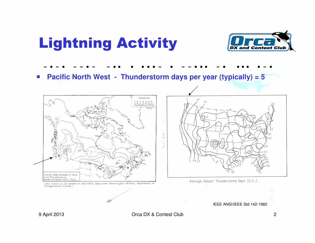
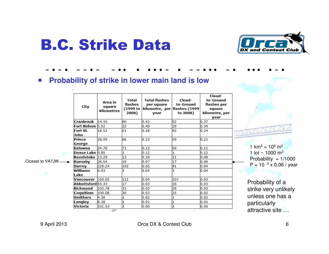
Current Distribution
� Percentage of strikes exceeding a given current
� 50 % will exceed 10,000 amps

- • - • - - • - - • • • • • • - • - - • • • - • • • • • - •
Orca DX & Contest Club 59 April 2013
Nearby Strikes
� Direct Strike is major threat; extensive damage & possible injury
� Nearby Strike will have much less effect but can induce significant voltage and current causing equipment failure
� At 300m (1000 ft), coax run of 30M
(100 ft) may have up to 15 kV induced
(~ 500V/m @ 300m x 30m)
� Equipment at risk
- • - • - - • - - • • • • • • - • - - • • • - • • • • • - •
Orca DX & Contest Club 69 April 2013
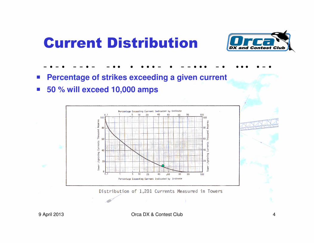
B.C. Strike Data
� Probability of strike in lower main land is low
Closest to VA7JW
1 km2 = 106 m2
1 lot ~ 1000 m2
Probability = 1/1000P = 10 -3 x 0.06 / year
Probability of a strike very unlikely unless one has a particularly attractive site …
- • - • - - • - - • • • • • • - • - - • • • - • • • • • - •
Orca DX & Contest Club 79 April 2013
But …
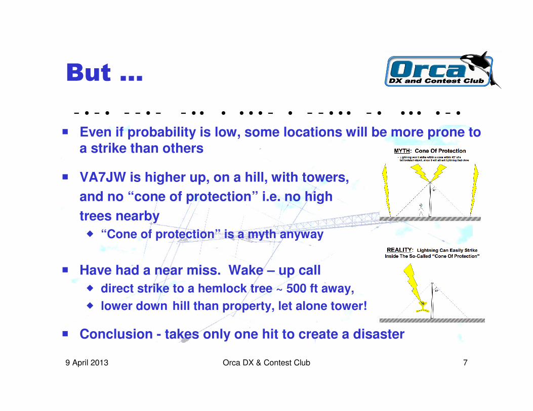
� Even if probability is low, some locations will be more prone toa strike than others
� VA7JW is higher up, on a hill, with towers,
and no “cone of protection” i.e. no high
trees nearby
� “Cone of protection” is a myth anyway
� Have had a near miss. Wake – up call
� direct strike to a hemlock tree ~ 500 ft away,
� lower down hill than property, let alone tower!
� Conclusion - takes only one hit to create a disaster
- • - • - - • - - • • • • • • - • - - • • • - • • • • • - •
Orca DX & Contest Club 89 April 2013
My Problem
� 9 Coax’s, 3 rotors, 2 control cables, 4 towers, highest = 65 ft
� “Copper” highway connected from outdoor antenna systems to the indoor radios, and the operator
� Very high risk of personal injury, household damage and radio equipment, if struck
� What are the costs of not having protection? (see above statement)
� What are the costs of installing protection ?
� as it turned out, materials cost ~ $1000

- • - • - - • - - • • • • • • - • - - • • • - • • • • • - •
Orca DX & Contest Club 99 April 2013
The Plan
Prevent destructive voltage and currentsfrom entering the shack
� Utilize lightning arrestor devices together with an effective grounding system to conduct lightning currents directly to earth
� Clamp surge voltages to manageable levels; Bypass surge currents to earth ground
� Every wire – coax, rotor, control, power would have a lightning arrestor
� Arrestors to be installed OUTSIDE the dwelling such that currents and voltages will be discouraged from entering the dwelling.
� Lightning is unpredictable – No Guarantees how well this will work…

- • - • - - • - - • • • • • • - • - - • • • - • • • • • - •
Orca DX & Contest Club 109 April 2013
Generic Lightning
Arrestors
1. Spark Gaps� RF in-line coaxial
2. Gas Tubes� RF in-line coaxial, rotor, control and power wiring
3. MOV, = Metal Oxide Varistor (voltage variable resistor)� Power and Control wiring - wire to ground
� Capable of shunting large currents, kA range, for microseconds
� Clamping voltages to low non-destructive levels i.e. < 600v
- • - • - - • - - • • • • • • - • - - • • • - • • • • • - •
Orca DX & Contest Club 119 April 2013
Introducing the “A28”
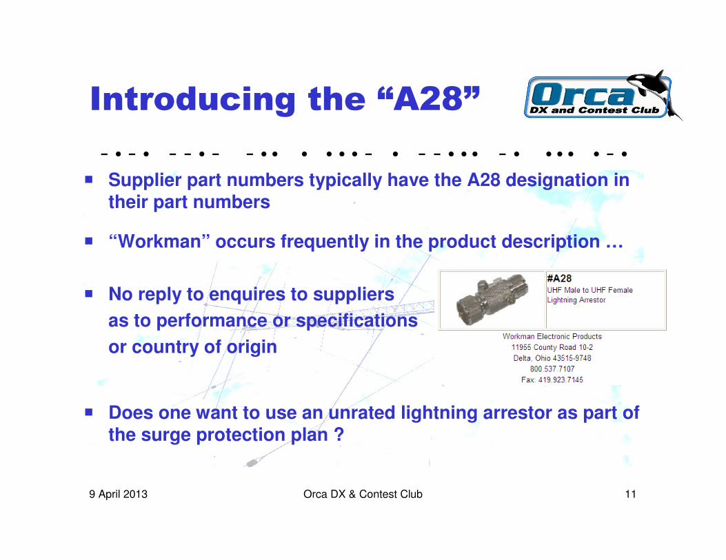
� Supplier part numbers typically have the A28 designation in their part numbers
� “Workman” occurs frequently in the product description …
� No reply to enquires to suppliers
as to performance or specifications
or country of origin
� Does one want to use an unrated lightning arrestor as part of the surge protection plan ?
- • - • - - • - - • • • • • • - • - - • • • - • • • • • - •
Orca DX & Contest Club 129 April 2013
How Does it Work ?
� Inserts directly in–line with coaxial cable
� Construction of the body and center conductor retains approximate coaxial cable characteristic impedance (50 ohm)
� The body is connected has a ground lug for wiring to earth for the purpose of diverting surge currents
� A screw on the body is gapped to the center conductor forming the protective spark gap
� High voltages will fire the gap diverting high currents to the body ground while maintaining a low clamping voltage between the coax center conductor and braid
� Time to investigate
- • - • - - • - - • • • • • • - • - - • • • - • • • • • - •
Orca DX & Contest Club 139 April 2013
“A28” Not all the Same
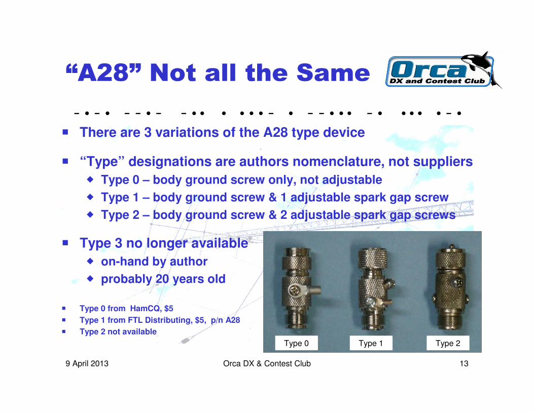
� There are 3 variations of the A28 type device
� “Type” designations are authors nomenclature, not suppliers
� Type 0 – body ground screw only, not adjustable
� Type 1 – body ground screw & 1 adjustable spark gap screw
� Type 2 – body ground screw & 2 adjustable spark gap screws
� Type 3 no longer available
� on-hand by author
� probably 20 years old
� Type 0 from HamCQ, $5
� Type 1 from FTL Distributing, $5, p/n A28
� Type 2 not available
Type 0 Type 1 Type 2
- • - • - - • - - • • • • • • - • - - • • • - • • • • • - •
Orca DX & Contest Club 149 April 2013
Look Inside
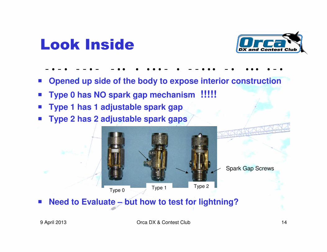
� Opened up side of the body to expose interior construction
� Type 0 has NO spark gap mechanism !!!!!
� Type 1 has 1 adjustable spark gap
� Type 2 has 2 adjustable spark gaps
� Need to Evaluate – but how to test for lightning?
Type 0Type 1 Type 2
Spark Gap Screws
- • - • - - • - - • • • • • • - • - - • • • - • • • • • - •
Orca DX & Contest Club 159 April 2013
Lightning Generator
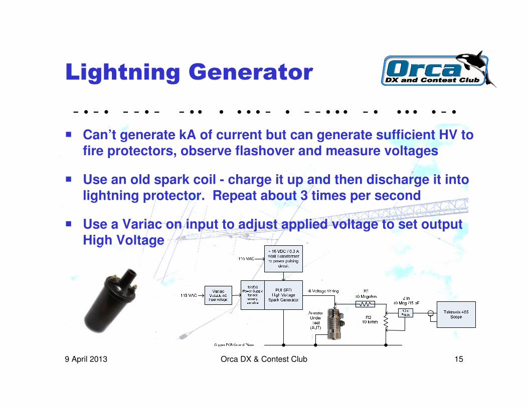
� Can’t generate kA of current but can generate sufficient HV to fire protectors, observe flashover and measure voltages
� Use an old spark coil - charge it up and then discharge it into lightning protector. Repeat about 3 times per second
� Use a Variac on input to adjust applied voltage to set output High Voltage

- • - • - - • - - • • • • • • - • - - • • • - • • • • • - •
Orca DX & Contest Club 169 April 2013
Test Setup
Variac to adjust115VAC input voltagewhich adjusts output
HV levels
‘Scope
Test Jig
AutomotiveSpark Coil
12VDC Power Supply for coil
Pulsing Circuit driving relay on coil primary
- • - • - - • - - • • • • • • - • - - • • • - • • • • • - •
Orca DX & Contest Club 179 April 2013
Type 0 Performance
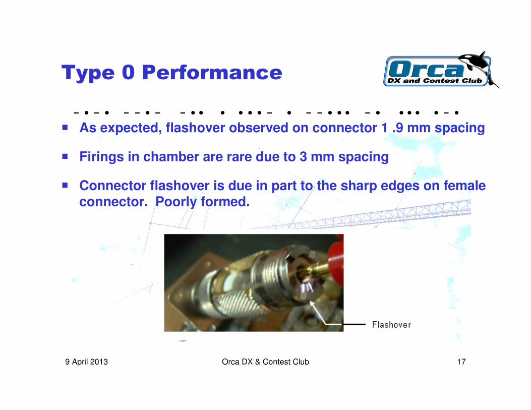
� As expected, flashover observed on connector 1 .9 mm spacing
� Firings in chamber are rare due to 3 mm spacing
� Connector flashover is due in part to the sharp edges on female connector. Poorly formed.
- • - • - - • - - • • • • • • - • - - • • • - • • • • • - •
Orca DX & Contest Club 189 April 2013
Type 1 Performance
� Gap set to 1.25 mm. Some firing seen in chamber
� Flashover occurs on connector at 2 mm spacing
� Again, the connector flashover seems due to sharp edges on female connector
- • - • - - • - - • • • • • • - • - - • • • - • • • • • - •
Orca DX & Contest Club 199 April 2013
Type 2 Performance
� Gap set to 1 mm.
� Firings observed in chamber.
� One gap will fire before the other as the gaps are not preciselyequal
� Female connector receptacle is better formed
� Performs as one would expect!

- • - • - - • - - • • • • • • - • - - • • • - • • • • • - •
Orca DX & Contest Club 209 April 2013
Flashover Waveform
� Variac voltage raised until firing or flashover occurs ~ 6 kV
� Gap fires virtually instantly; estimated arc voltage ~ 200 V
� Arc lasts for ~ 140 usec until coil energy is dissipated.
� Ringing observed as residual energy dissipates after gap quenches.
- • - • - - • - - • • • • • • - • - - • • • - • • • • • - •
Orca DX & Contest Club 219 April 2013
Expanded Waveform
� Expanded view of flashover ignition
� Shows instantaneous rise time
� ~ 1 usec settling time to gap voltage drop
- • - • - - • - - • • • • • • - • - - • • • - • • • • • - •
Orca DX & Contest Club 229 April 2013
A28 Observations
� Spark gap fires < 1 usec. Very fast protection
� Gap voltage is estimated to clamp to ~ 200V in 1 usec
� As a first line of defense, the air spark gap method may well divert significant energy, quickly
� No indication of the amount of current that can be sustained and for how long
� Suppressor will divert currents on the braid if mounted at towerbase at ground level & gap will divert center conductor currentsto ground while sustaining a low voltage

- • - • - - • - - • • • • • • - • - - • • • - • • • • • - •
Orca DX & Contest Club 239 April 2013
Which to Use?
� Type 0 - no adjustable gap
� provided body is well grounded, it will divert surge currents onbraid
� flashover occurs on connector
� Type 1 – one adjustable gap
� provided body is well grounded, will divert surge currents on braid
� gap can be adjusted to flash over before connector end
� how to adjust the GAP? - procedure next slide
� Type 2 – two adjustable gaps
� no longer available but best designed
Dx Engineering product
- • - • - - • - - • • • • • • - • - - • • • - • • • • • - •
Orca DX & Contest Club 249 April 2013
Adjusting the Gap
� Procedure: note – breakdown voltage for air, 3 kV / mm
� Discard the supplied gap screw. Save the nut or supply a new Stainless nut� Use a 4 x 10 mm metric machine stainless screw to replace the supplied screw� File, or grind with a Dremel © tool, a 4 sided point, 45 degree angle is good� Thread the nut on the screw up to the head, just snug� Thread this assembly into the vacated screw gap hole� Connect an ohmmeter between the center conductor and the casing� Screw the screw in until it shorts to the internal center conductor� The “thread rate” on the 10 mm screw is about 0.7 mm per turn (1 revolution)� Back off the screw min 1 to ~ 1-1/2 turns. This provides ~0.7 to 1.5 mm gap� Would not recommend less as ambient thermal change may compromise gap� Lock the screw down by tightening the nut against the case. Careful not to
disturb the setting� Use non-permanent LOCTITE © on the joint to weather seal and hold the gap
- • - • - - • - - • • • • • • - • - - • • • - • • • • • - •
Orca DX & Contest Club 259 April 2013
2. The Gas Tube
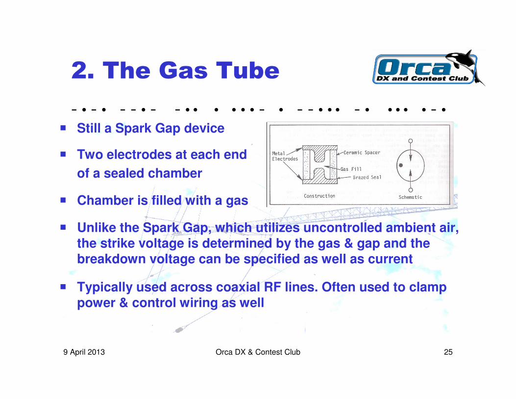
� Still a Spark Gap device
� Two electrodes at each end
of a sealed chamber
� Chamber is filled with a gas
� Unlike the Spark Gap, which utilizes uncontrolled ambient air, the strike voltage is determined by the gas & gap and the breakdown voltage can be specified as well as current
� Typically used across coaxial RF lines. Often used to clamp power & control wiring as well

- • - • - - • - - • • • • • • - • - - • • • - • • • • • - •
Orca DX & Contest Club 269 April 2013
Gas Tube Characteristics
� Gas tubes are tested to industry “standard” lightning specs.
� For coaxial cable lightning surge suppression
Example for a Typical Strike
Rise Time t1 ~ 8 ����secondsCrest ~ 25 kAFall time t2 ~ 20 ����seconds to half of crest value

- • - • - - • - - • • • • • • - • - - • • • - • • • • • - •
Orca DX & Contest Club 279 April 2013
Coaxial Gas Tube
� A Spark Gap device embedded in a coaxial housing which can be inserted in-line like the A28 device
� Many to choose from � ratings 200 W up, to > 1 GHz
Alpha Delta $70
MFJ-272$30 Poly Phasor
$65
Jet Stream
$55
L-Com UHF$15

- • - • - - • - - • • • • • • - • - - • • • - • • • • • - •
Orca DX & Contest Club 289 April 2013
Typical Features
� In-Line with ground lug or ground panel mounting body
� Connector options� typically PL style, male and female combinations
� N style male and female options, not all suppliers
� Performance� Frequency 1 MHz to 1 GHz or greater, SWR < 1.5:1
� Insertion losses typically 0.1 dB
� Power rating, anywhere from 200 W to > kW
� Gas Tube � Typically replaceable. Optional voltages available depending on
transmit power handling requirements

- • - • - - • - - • • • • • • - • - - • • • - • • • • • - •
Orca DX & Contest Club 299 April 2013
VA7JW Selection
� L-Com Product AL-UFUFB-6
� Excellent, detailed specifications
� DC – 3GHz / SWR < 1.3:1
� Insertion Loss < 0.4 dB to 3 GHz
� Excellent variety of connectors (both PL and N)
� Supplied with 600V gas tube. Other voltages available
� PL style $15 US / N style $25 Replacement gas tubes, $5 ea
� Stock, Ships UPS (UPS expensive outside of USA, “border” fee of $45 per shipment)
UHF-Female to UHF-Female Bulkhead 0-3 GHz 600V Lightning Protector - AL-UFUFB-6
� For 1-of local supply, Burnaby Radio, variety $35 > $60

- • - • - - • - - • • • • • • - • - - • • • - • • • • • - •
Orca DX & Contest Club 309 April 2013
Flashover Waveform
� 600 V gas tube installed
� Instantaneous clamping, no overshoot
� Clamping voltage is about 10V
� Ringing is minimal as energy is very quickly and completely suppressed
- • - • - - • - - • • • • • • - • - - • • • - • • • • • - •
Orca DX & Contest Club 319 April 2013
Expanded Waveform
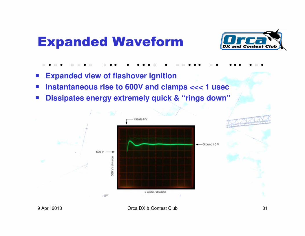
� Expanded view of flashover ignition
� Instantaneous rise to 600V and clamps <<< 1 usec
� Dissipates energy extremely quick & “rings down”

- • - • - - • - - • • • • • • - • - - • • • - • • • • • - •
Orca DX & Contest Club 329 April 2013
Observations
� Superior performance to the A28 Spark Gap
� No connector flashovers
� Clamp time estimated in nanosec’s; not measureable
� Clamp voltage very low, estimated 10 V

- • - • - - • - - • • • • • • - • - - • • • - • • • • • - •
Orca DX & Contest Club 339 April 2013
Comparison A28 / L-Com
� SWR
� Insertion Loss
� Clamping Characteristics
Used AIM-4170 Vector Impedance Meter
Tectronix 465 ‘scope

- • - • - - • - - • • • • • • - • - - • • • - • • • • • - •
Orca DX & Contest Club 349 April 2013
Axial Leaded Gas Tube
� Same construction and specs as used
with the coaxial gas tube arrestor
� Selected 150V to protect low voltage
< 30 V wired cable (not coax)
� Surge rating 20 kA 8 x 20 usec, once
� Firing voltages in the 75 to 600 V range
� Digikey Part number 2027-15-BLF-ND
� 100 pieces, $85

- • - • - - • - - • • • • • • - • - - • • • - • • • • • - •
Orca DX & Contest Club 359 April 2013
3. The MOV
� Metal Oxide Varistor is a voltage dependent resistor
� Looks like a Disc Ceramic Capacitor but it is not
� At low voltages it is open circuit (megohms)
� At some specified higher voltage, the resistancefalls to a low value (a few ohms or less)
� Large currents can flow and the voltage is clamped to the rated voltage of the varistor, i.e. 100V
� Not polarity sensitive. Can be used to clamp AC or DC circuits
� Not suitable for RF
- • - • - - • - - • • • • • • - • - - • • • - • • • • • - •
Orca DX & Contest Club 369 April 2013
MOV Characteristics
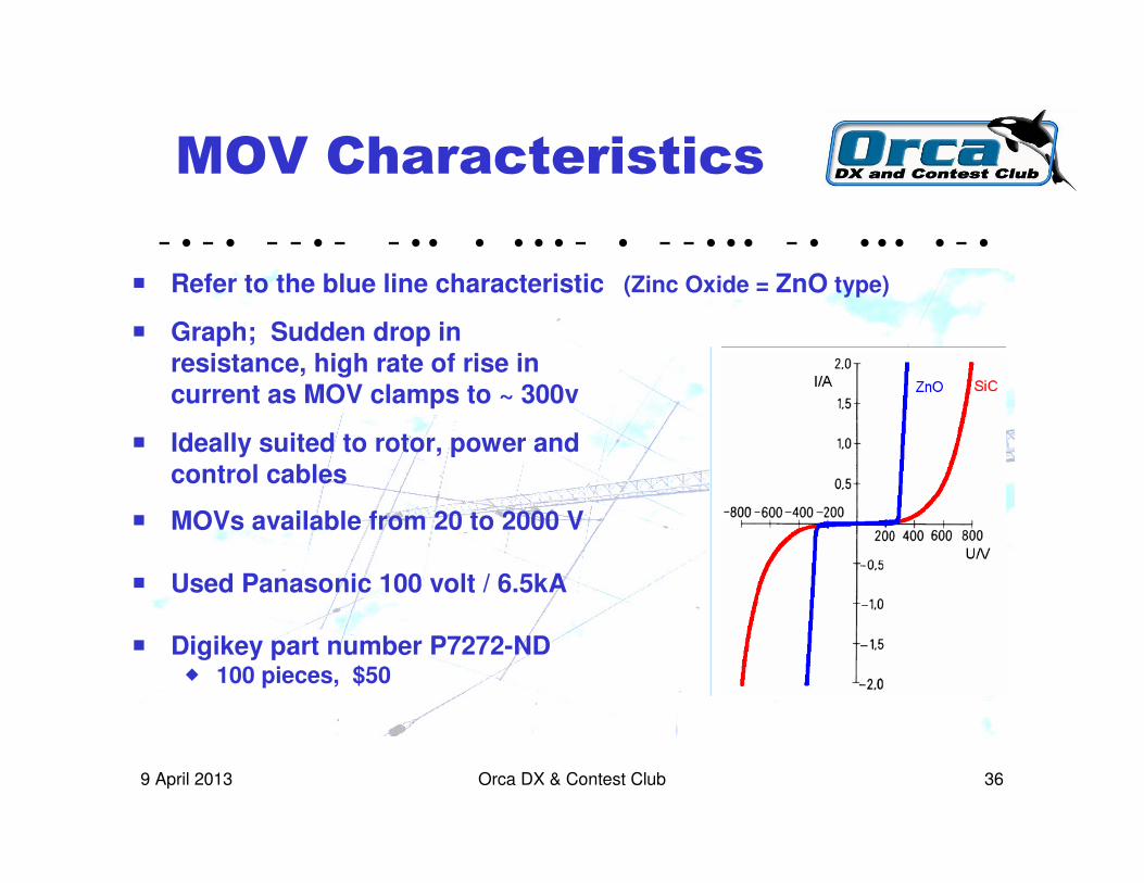
� Refer to the blue line characteristic (Zinc Oxide = ZnO type)
� Graph; Sudden drop in resistance, high rate of rise in current as MOV clamps to ~ 300v
� Ideally suited to rotor, power andcontrol cables
� MOVs available from 20 to 2000 V
� Used Panasonic 100 volt / 6.5kA
� Digikey part number P7272-ND� 100 pieces, $50
- • - • - - • - - • • • • • • - • - - • • • - • • • • • - •
Orca DX & Contest Club 379 April 2013
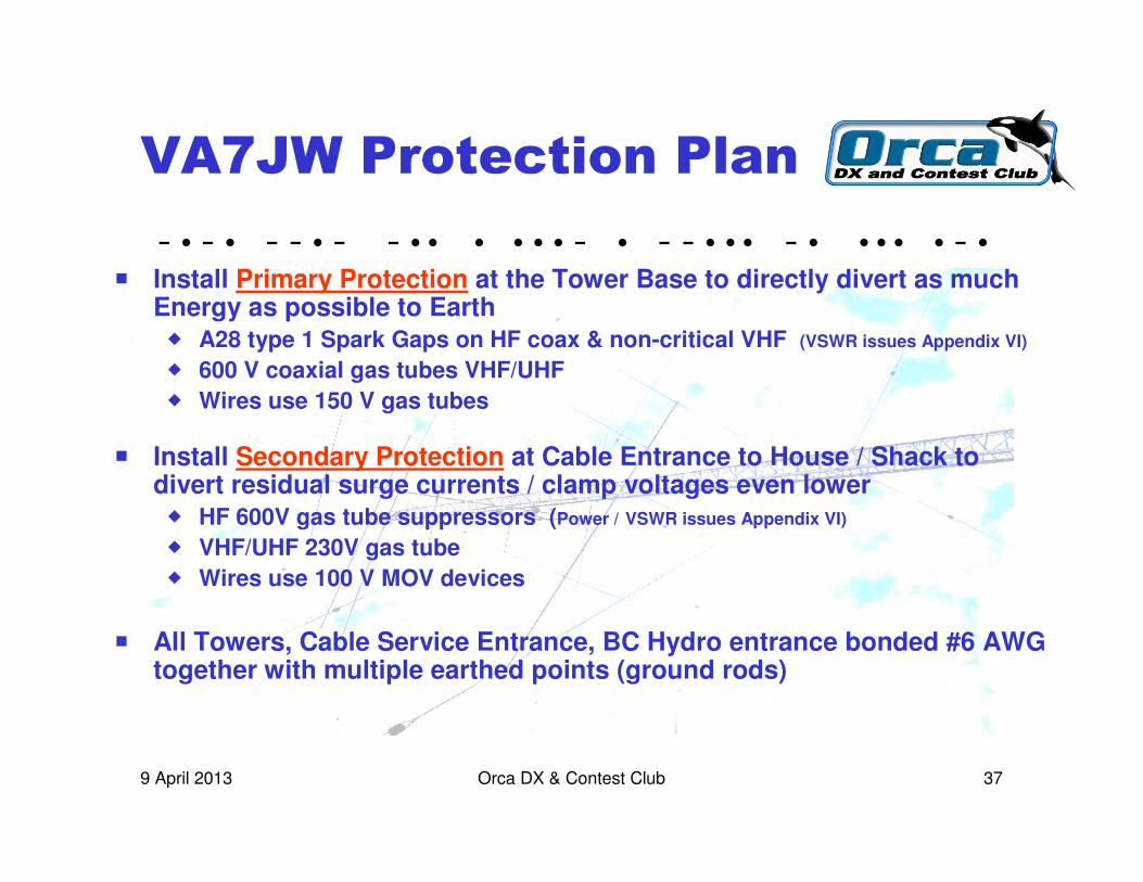
VA7JW Protection Plan
� Install Primary Protection at the Tower Base to directly divert as much Energy as possible to Earth � A28 type 1 Spark Gaps on HF coax & non-critical VHF (VSWR issues Appendix VI)
� 600 V coaxial gas tubes VHF/UHF
� Wires use 150 V gas tubes
� Install Secondary Protection at Cable Entrance to House / Shack to divert residual surge currents / clamp voltages even lower� HF 600V gas tube suppressors (Power / VSWR issues Appendix VI)
� VHF/UHF 230V gas tube
� Wires use 100 V MOV devices
� All Towers, Cable Service Entrance, BC Hydro entrance bonded #6 AWG together with multiple earthed points (ground rods)
- • - • - - • - - • • • • • • - • - - • • • - • • • • • - •
Orca DX & Contest Club 389 April 2013
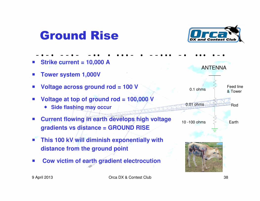
Ground Rise
� Strike current = 10,000 A
� Tower system 1,000V
� Voltage across ground rod = 100 V
� Voltage at top of ground rod = 100,000 V
� Side flashing may occur
� Current flowing in earth develops high voltage
gradients vs distance = GROUND RISE
� This 100 kV will diminish exponentially with
distance from the ground point
� Cow victim of earth gradient electrocution
0.1 ohms
0.01 ohms
10 -100 ohms Earth
Rod
Feed line& Tower
ANTENNA

- • - • - - • - - • • • • • • - • - - • • • - • • • • • - •
Orca DX & Contest Club 399 April 2013
Ground Rise & Grounding
� Amount of ground rise, the gradients, the distance “out” where harmful levels may exist, which directions, these are all unpredictable due to circumstance of soils, terrain, etc
� Voltage gradients between system components are unpredictable
� Best one can do is tie system ground to earth ground at frequentpoints to try and have system levels closely tied to the ground rise.
� Objective is to minimize potential differences between ground rise and antenna, and radio systems, and operator

- • - • - - • - - • • • • • • - • - - • • • - • • • • • - •
Orca DX & Contest Club 409 April 2013
System Diagram
� Primary at tower bases & Secondary protection at house entry
� Bonded ground system tying all major components together� Tower bases (all 4) direct to earth� Cable service entrance� Hydro service entrance� Copper cold water pipe� Equipment ground connected
� Frequent use of ground rods

- • - • - - • - - • • • • • • - • - - • • • - • • • • • - •
Orca DX & Contest Club 419 April 2013
Ground Wire Sizing
� What Gauge wire is needed to carry a strike current ?
� Wire Melt, called FUSING as in blowing a fuse, is the issue
� #6 copper is Canadian
Electrical Code
requirement
� For 70 ����sec, fusing
current ~ 500 kA
� For 8 x 20uS strike at
10 kA, appears as
though #6 will surviveDon White Consultants
- • - • - - • - - • • • • • • - • - - • • • - • • • • • - •
Orca DX & Contest Club 429 April 2013
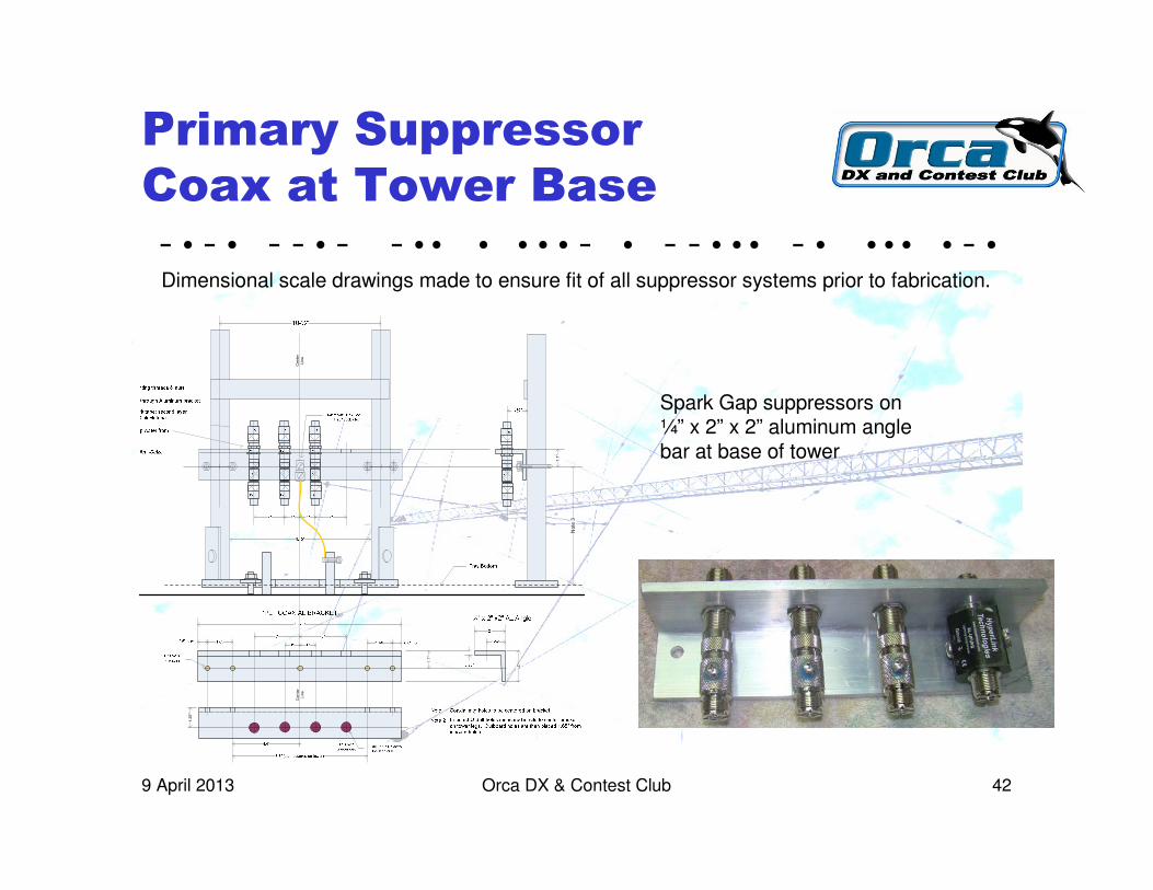
Primary Suppressor
Coax at Tower Base
Dimensional scale drawings made to ensure fit of all suppressor systems prior to fabrication.
1.1"
Center
Line
2"
1.1"
1.25"
Center
Line
Note 3
Spark Gap suppressors on¼” x 2” x 2” aluminum anglebar at base of tower

- • - • - - • - - • • • • • • - • - - • • • - • • • • • - •
Orca DX & Contest Club 439 April 2013
Primary Suppressor
12 Wire at Tower Base
Dimensional drawings made to ensure fit of all suppressor systems prior to fabrication. i.e

- • - • - - • - - • • • • • • - • - - • • • - • • • • • - •
Orca DX & Contest Club 449 April 2013
Primary on Tower Bases
HF TOWER
VHF / UHF TOWER
Gas Tube WireSuppressor Enclosures
2 places – Rotor & SteppIR
Two A28 SparkGap Arrestors1.5 mm gap
Six, 600V Gas Tube Suppressors
on 2 bars
150 V Gas Tube Wire Suppressor
Enclosures3 places – 2 Rotors
& Power
1 Gas Tube Suppressorat 600V
Black, Split Loom for WX & UV protectionof exposed cables.
VERY durable
- • - • - - • - - • • • • • • - • - - • • • - • • • • • - •
Orca DX & Contest Club 459 April 2013
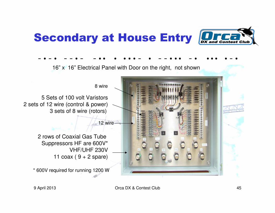
Secondary at House Entry
2 rows of Coaxial Gas Tube Suppressors HF are 600V*
VHF/UHF 230V11 coax ( 9 + 2 spare)
5 Sets of 100 volt Varistors2 sets of 12 wire (control & power)
3 sets of 8 wire (rotors)
16” x 16” Electrical Panel with Door on the right, not shown
12 wire
8 wire
* 600V required for running 1200 W
- • - • - - • - - • • • • • • - • - - • • • - • • • • • - •
Orca DX & Contest Club 469 April 2013
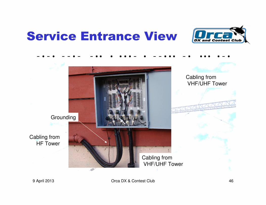
Service Entrance View
Cabling fromHF Tower
Cabling fromVHF/UHF Tower
Grounding
Cabling fromVHF/UHF Tower

- • - • - - • - - • • • • • • - • - - • • • - • • • • • - •
Orca DX & Contest Club 479 April 2013
Operating Results
� Good – no issues through hot summer, wet winter
� Suppressors had had no measurable affect on performance
1 through 450 MHz
� VSWR’s good & stable
� No measurable affect on any of the rotor, SteppIR control or power systems.
� Have not yet been hit by lightning; ultimate performance TBD
- • - • - - • - - • • • • • • - • - - • • • - • • • • • - •
Orca DX & Contest Club 489 April 2013
Appendices
� Appendix I - Coaxial suppresser cost
� Appendix II - Wire suppresser cost
� Appendix III - A28 Type 0 Evaluation
� Appendix IV - A28 Type 1 Evaluation
� Appendix V - A28 Type 2 Evaluation
� Appendix VI – Power Rating Gas Tubes
� Appendix VII - Inductance
- • - • - - • - - • • • • • • - • - - • • • - • • • • • - •
Orca DX & Contest Club 499 April 2013
Appendix I. Cost – Coaxial Cable
Suppressor Parts
� Type 1 Coaxial Spark Gap $5 ea
� UHF-UHF Coaxial Gas Tube $15 ea
� N – N type Coaxial gas Tube $26 ea
� PL-259 Male coax connectors $3 ea
� N style 2 piece coax connector $5.50
� Cabinet, metal plates, angles, U bolts,screws, ground wire, clamps, ….. ~ $500
� Exchange, shipping, brokerage, duties, taxes not included
- • - • - - • - - • • • • • • - • - - • • • - • • • • • - •
Orca DX & Contest Club 509 April 2013
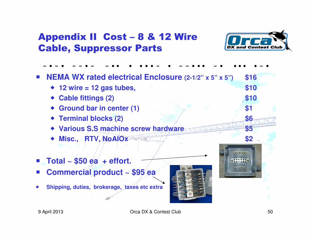
Appendix II Cost – 8 & 12 Wire
Cable, Suppressor Parts
� NEMA WX rated electrical Enclosure (2-1/2” x 5” x 5”) $16
� 12 wire = 12 gas tubes, $10
� Cable fittings (2) $10
� Ground bar in center (1) $1
� Terminal blocks (2) $6
� Various S.S machine screw hardware $5
� Misc., RTV, NoAlOx $2
� Total ~ $50 ea + effort.
� Commercial product ~ $95 ea
� Shipping, duties, brokerage, taxes etc extra

- • - • - - • - - • • • • • • - • - - • • • - • • • • • - •
Orca DX & Contest Club 519 April 2013
Appendix III. Type 0
No Spark Gap
� No spark gap. Assume spacing from center conductor to body IS the gap and adjusted to protect coax etc
� Gap on female end of connector is 1.9 mm whereas there is a 3 mm gap between center conductor and body ? ? ?
� Can you guess which one flashes over first?
� Flashover is calculated to be ~ 3 kV/mm for 3 x 1.9 = 5.7 kV
1.9 mm gap 3 mm chamber gap

- • - • - - • - - • • • • • • - • - - • • • - • • • • • - •
Orca DX & Contest Club 529 April 2013
Appendix IV Type 1
1 Spark Gap
� There is an adjustable spark gap. End of screw is FLAT – should be pointed to enhance initiation of flashover.
� Factory set gap tight against the external nut is ~ 1.25 mm
� Flashover voltage estimated at 3.75 kV
� The gap on female end is 2 mm, same as chamber
� The center conductor leaves a lot to be desired as the two piececonstruction is bent and the adjustable gap is compromised
2 mm gap 2 mm chamber gap
- • - • - - • - - • • • • • • - • - - • • • - • • • • • - •
Orca DX & Contest Club 539 April 2013
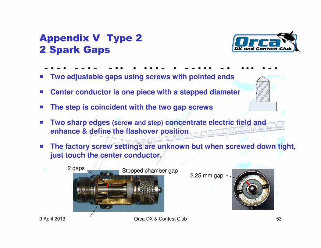
Appendix V Type 2
2 Spark Gaps
� Two adjustable gaps using screws with pointed ends
� Center conductor is one piece with a stepped diameter
� The step is coincident with the two gap screws
� Two sharp edges (screw and step) concentrate electric field and enhance & define the flashover position
� The factory screw settings are unknown but when screwed down tight, just touch the center conductor.
Stepped chamber gap2.25 mm gap
2 gaps
- • - • - - • - - • • • • • • - • - - • • • - • • • • • - •
Orca DX & Contest Club 549 April 2013
Appendix VI
RF Power Considerations
� Coaxial gas tube rating typical max 600V
� Running power > 2 kW ?
� RMS voltage on 50 ohm line = 316V x 1.414 = 447V peak
� This is for VSWR = 1:1
� For VSWR = 2:1, V peak = 895v, probable gas tube firing

- • - • - - • - - • • • • • • - • - - • • • - • • • • • - •
Orca DX & Contest Club 559 April 2013
Appendix VII
Inductance
� The “resistive” model of voltage drop is incomplete.
� Inductance associated with wiring develops much higher voltages
� Relationship between Voltage and Current for an inductance
� V is the voltage developed across and inductor
� L is the inductance value
� i is the current
� t is time
� di/dt is the rate of change of current with time, amps per sec
� With high rate of di/dt, kA/ ����S large voltage drops develop

- • - • - - • - - • • • • • • - • - - • • • - • • • • • - •
Orca DX & Contest Club 569 April 2013
Appendix VII continued
Inductance Calculation
� One foot of #6 AWG copper
� Inductance ~ 0.26 ����H per foot
� Resistance ~ 0.0004 ohm per foot
� Strike of 8 ����S rise time x 10,000 Amperes
� Resistive Voltage drop / foot at 10 kA = 4 volts / foot
� Inductive voltage drop / foot at 10 kA/8 ����s = 325 volts / foot
� The impedance is clearly limited by L
Top Related