


Languages
Pages
Legal


2013-2015 Microchip Technology Inc. DS40001718D
MGC3030/3130 GestIC® LibraryInterface Description
User’s Guide

DS40001718D-page 2 2013-2015 Microchip Technology Inc.
Information contained in this publication regarding deviceapplications and the like is provided only for your convenienceand may be superseded by updates. It is your responsibility toensure that your application meets with your specifications.MICROCHIP MAKES NO REPRESENTATIONS ORWARRANTIES OF ANY KIND WHETHER EXPRESS ORIMPLIED, WRITTEN OR ORAL, STATUTORY OROTHERWISE, RELATED TO THE INFORMATION,INCLUDING BUT NOT LIMITED TO ITS CONDITION,QUALITY, PERFORMANCE, MERCHANTABILITY ORFITNESS FOR PURPOSE. Microchip disclaims all liabilityarising from this information and its use. Use of Microchipdevices in life support and/or safety applications is entirely atthe buyer’s risk, and the buyer agrees to defend, indemnify andhold harmless Microchip from any and all damages, claims,suits, or expenses resulting from such use. No licenses areconveyed, implicitly or otherwise, under any Microchipintellectual property rights.
Note the following details of the code protection feature on Microchip devices:
• Microchip products meet the specification contained in their particular Microchip Data Sheet.
• Microchip believes that its family of products is one of the most secure families of its kind on the market today, when used in the intended manner and under normal conditions.
• There are dishonest and possibly illegal methods used to breach the code protection feature. All of these methods, to our knowledge, require using the Microchip products in a manner outside the operating specifications contained in Microchip’s Data Sheets. Most likely, the person doing so is engaged in theft of intellectual property.
• Microchip is willing to work with the customer who is concerned about the integrity of their code.
• Neither Microchip nor any other semiconductor manufacturer can guarantee the security of their code. Code protection does not mean that we are guaranteeing the product as “unbreakable.”
Code protection is constantly evolving. We at Microchip are committed to continuously improving the code protection features of ourproducts. Attempts to break Microchip’s code protection feature may be a violation of the Digital Millennium Copyright Act. If such actsallow unauthorized access to your software or other copyrighted work, you may have a right to sue for relief under that Act.
Microchip received ISO/TS-16949:2009 certification for its worldwide headquarters, design and wafer fabrication facilities in Chandler and Tempe, Arizona; Gresham, Oregon and design centers in California and India. The Company’s quality system processes and procedures are for its PIC® MCUs and dsPIC® DSCs, KEELOQ® code hopping devices, Serial EEPROMs, microperipherals, nonvolatile memory and analog products. In addition, Microchip’s quality system for the design and manufacture of development systems is ISO 9001:2000 certified.
QUALITY MANAGEMENT SYSTEM CERTIFIED BY DNV
== ISO/TS 16949 ==
Trademarks
The Microchip name and logo, the Microchip logo, dsPIC, FlashFlex, flexPWR, JukeBlox, KEELOQ, KEELOQ logo, Kleer, LANCheck, MediaLB, MOST, MOST logo, MPLAB, OptoLyzer, PIC, PICSTART, PIC32 logo, RightTouch, SpyNIC, SST, SST Logo, SuperFlash and UNI/O are registered trademarks of Microchip Technology Incorporated in the U.S.A. and other countries.
The Embedded Control Solutions Company and mTouch are registered trademarks of Microchip Technology Incorporated in the U.S.A.
Analog-for-the-Digital Age, BodyCom, chipKIT, chipKIT logo, CodeGuard, dsPICDEM, dsPICDEM.net, ECAN, In-Circuit Serial Programming, ICSP, Inter-Chip Connectivity, KleerNet, KleerNet logo, MiWi, MPASM, MPF, MPLAB Certified logo, MPLIB, MPLINK, MultiTRAK, NetDetach, Omniscient Code Generation, PICDEM, PICDEM.net, PICkit, PICtail, RightTouch logo, REAL ICE, SQI, Serial Quad I/O, Total Endurance, TSHARC, USBCheck, VariSense, ViewSpan, WiperLock, Wireless DNA, and ZENA are trademarks of Microchip Technology Incorporated in the U.S.A. and other countries.
SQTP is a service mark of Microchip Technology Incorporated in the U.S.A.
Silicon Storage Technology is a registered trademark of Microchip Technology Inc. in other countries.
GestIC is a registered trademarks of Microchip Technology Germany II GmbH & Co. KG, a subsidiary of Microchip Technology Inc., in other countries.
All other trademarks mentioned herein are property of their respective companies.
© 2013-2015, Microchip Technology Incorporated, Printed in the U.S.A., All Rights Reserved.
ISBN: 978-1-63276-974-9

MGC3030/3130 GestIC® LIBRARY
INTERFACE DESCRIPTIONTable of Contents
Preface ........................................................................................................................... 5
Chapter 1. Introduction1.1 Purpose of this Document ............................................................................ 111.2 MGC3X30 Software Architecture ................................................................. 111.3 GestIC® Library ............................................................................................ 121.4 Bridge ........................................................................................................... 121.5 GestIC API ................................................................................................... 131.6 Application Software ..................................................................................... 13
Chapter 2. MGC3030/3130 Host Interface2.1 MGC3X30 Hardware Interface ..................................................................... 152.2 Usage of Transfer Status Line (TS) .............................................................. 162.3 Coding Example ........................................................................................... 17
Chapter 3. GestIC Library Message Interface3.1 Messages Overview ..................................................................................... 193.2 Message Format .......................................................................................... 203.3 Message Header .......................................................................................... 203.4 Message Payload ......................................................................................... 213.5 Message Coding and Decoding ................................................................... 21
3.5.1 Header Extraction ...................................................................................... 213.5.2 Payload Extraction .................................................................................... 22
3.6 Message Control Flow and Coding Examples ............................................. 233.6.1 Message Control Flow ............................................................................... 233.6.2 Read GestIC Library Version .................................................................... 24
3.6.2.1 Example: Request FW Version Info .......................................... 243.6.3 Run-Time Control ...................................................................................... 25
3.6.3.1 Example: Enable Approach Detection ....................................... 253.6.3.2 Example: Enable All Gestures ................................................... 253.6.3.3 Example: Enable Data Output ................................................... 263.6.3.4 Example: Lock Data Output ....................................................... 26
3.6.4 Sensor Data Output ................................................................................... 273.6.4.1 Example: Read Sensor Data Output ......................................... 27
Chapter 4. GestIC Library Message Reference4.1 System_Status ............................................................................................. 294.2 Request_Message ....................................................................................... 314.3 Fw_Version_Info .......................................................................................... 324.4 Set_Runtime_Parameter .............................................................................. 33
4.4.1 Trigger ....................................................................................................... 334.4.2 Make Persistent ......................................................................................... 344.4.3 Analog Front End (AFE) Category ............................................................ 34
2013-2015 Microchip Technology Inc. DS40001718D-page 3

MGC3030/3130 GestIC® Library Interface Description
4.4.3.1 Signal Matching .........................................................................344.4.3.2 Electrode Mapping .....................................................................35
4.4.4 Digital Signal Processing (DSP) Category .................................................364.4.4.1 Transmit Frequency Selection ...................................................364.4.4.2 Touch Detection .........................................................................374.4.4.3 Approach Detection ...................................................................37
4.4.5 System Category .......................................................................................384.4.5.1 AirWheel ....................................................................................384.4.5.2 Gesture Processing (HMM) .......................................................384.4.5.3 Calibration Operation Mode .......................................................384.4.5.4 Data Output Enable Mask ..........................................................394.4.5.5 Data Output Lock Mask .............................................................404.4.5.6 Data Output Request Mask ........................................................414.4.5.7 Gesture in Progress Flag Control ..............................................41
4.5 Sensor_Data_Output .................................................................................... 42
Chapter 5. Messages for GestIC Library Update5.1 Library Loader Update Procedure ................................................................ 455.2 Fw_Update_Start ......................................................................................... 465.3 Fw_Update_Block ........................................................................................ 475.4 Fw_Update_Completed ................................................................................ 49
Appendix A. I2C™ Command Examples
Appendix B. Glossary
Worldwide Sales and Service .....................................................................................61
DS40001718D-page 4 2013-2015 Microchip Technology Inc.

MGC3030/3130 GestIC® LIBRARY
INTERFACE DESCRIPTIONPreface
INTRODUCTION
This chapter contains general information that will be useful to know before using the MGC3030/3130 GestIC® Library Interface. Items discussed in this chapter include:
• Document Layout
• Conventions Used in this Guide
• Warranty Registration
• Recommended Reading
• The Microchip Web Site
• Development Systems Customer Change Notification Service
• Customer Support
• Document Revision History
DOCUMENT LAYOUT
This document describes the MGC3030/3130 GestIC Library and is organized as follows:
• Chapter 1. Introduction
• Chapter 2. MGC3030/3130 Host Interface
• Chapter 3. GestIC Library Message Interface
• Chapter 4. GestIC Library Message Reference
• Chapter 5. Messages for GestIC Library Update
NOTICE TO CUSTOMERS
All documentation becomes dated, and this manual is no exception. Microchip tools and documentation are constantly evolving to meet customer needs, so some actual dialogs and/or tool descriptions may differ from those in this document. Please refer to our web site (www.microchip.com) to obtain the latest documentation available.
Documents are identified with a “DS” number. This number is located on the bottom of each page, in front of the page number. The numbering convention for the DS number is “DSXXXXXA”, where “XXXXX” is the document number and “A” is the revision level of the document.
For the most up-to-date information on development tools, see the MPLAB® IDE on-line help. Select the Help menu, and then Topics to open a list of available online help files.
2013-2015 Microchip Technology Inc. DS40001718D-page 5

MGC3030/3130 GestIC® Library Interface Description
CONVENTIONS USED IN THIS GUIDE
This manual uses the following documentation conventions:
DOCUMENT CONVENTIONS
Description Represents Examples
Arial font:
Italic characters Referenced books MPLAB IDE User’s Guide
Emphasized text ...is the only compiler...
Initial caps A window the Output window
A dialog the Settings dialog
A menu selection select Enable Programmer
Quotes A field name in a window or dialog
“Save project before build”
Underlined, italic text with right angle bracket
A menu path File>Save
Bold characters A dialog button Click OK
A tab Click the Power tab
N‘Rnnnn A number in verilog format, where N is the total number of digits, R is the radix and n is a digit.
4‘b0010, 2‘hF1
Text in angle brackets < > A key on the keyboard Press <Enter>, <F1>
Courier New font:
Plain Courier New Sample source code #define START
Filenames autoexec.bat
File paths c:\mcc18\h
Keywords _asm, _endasm, static
Command-line options -Opa+, -Opa-
Bit values 0, 1
Constants 0xFF, ‘A’
Italic Courier New A variable argument file.o, where file can be any valid filename
Square brackets [ ] Optional arguments mcc18 [options] file [options]
Curly brackets and pipe character: |
Choice of mutually exclusive arguments; an OR selection
errorlevel 0|1
Ellipses... Replaces repeated text var_name [, var_name...]
Represents code supplied by user
void main (void) ...
DS40001718D-page 6 2013-2015 Microchip Technology Inc.
Preface
WARRANTY REGISTRATION
Please complete the enclosed Warranty Registration Card and mail it promptly. Sending in the Warranty Registration Card entitles users to receive new product updates. Interim software releases are available at the Microchip web site.
RECOMMENDED READING
This user’s guide describes how to use MGC3030/3130 GestIC Library Interface. Other useful documents are listed below. The following Microchip documents are available and recommended as supplemental reference resources.
• “MGC3030/3130 3D Gesture Controller Data Sheet” (DS40001667) – Consult this document for information regarding the MGC3030/3130 3D Tracking and Gesture Controller.
• “Aurea Graphical User Interface User’s Guide” (DS40001681) – Describes how to use the MGC3X30 Aurea Graphical User Interface.
• “GestIC® Design Guide” (DS40001716) – This document describes the GestIC system characteristic parameters and the design process. It enables the user to generate a good electrode design and to parameterize the full GestIC system.
Note: The “MGC3030/3130 GestIC® Library Interface Description User’s Guide” applies to the MGC3030 and MGC3130 parts. Throughout this document the term MGC3X30 will be representative for these two parts.
2013-2015 Microchip Technology Inc. DS40001718D-page 7

MGC3030/3130 GestIC® Library Interface Description
THE MICROCHIP WEB SITE
Microchip provides online support via our web site at www.microchip.com. This web site is used as a means to make files and information easily available to customers. Information about GestIC technology and MGC3X30 can be directly accessed via http://www.microchip.com/gestic.
DEVELOPMENT SYSTEMS CUSTOMER CHANGE NOTIFICATION SERVICE
Microchip’s customer notification service helps keep customers current on Microchip products. Subscribers will receive e-mail notification whenever there are changes, updates, revisions or errata related to a specified product family or development tool of interest.
To register, access the Microchip web site at www.microchip.com, click on Customer Change Notification and follow the registration instructions.
The Development Systems product group categories are:
• Compilers – The latest information on Microchip C compilers, assemblers, linkers and other language tools. These include all MPLAB® C compilers; all MPLAB assemblers (including MPASM™ assembler); all MPLAB linkers (including MPLINK™ object linker); and all MPLAB librarians (including MPLIB™ object librarian).
• Emulators – The latest information on Microchip in-circuit emulators.This includes the MPLAB® REAL ICE™ and MPLAB ICE 2000 in-circuit emulators.
• In-Circuit Debuggers – The latest information on the Microchip in-circuit debuggers. This includes MPLAB ICD 3 in-circuit debuggers and PICkit™ 3 debug express.
• MPLAB IDE – The latest information on Microchip MPLAB IDE, the Windows Integrated Development Environment for development systems tools. This list is focused on the MPLAB IDE, MPLAB IDE Project Manager, MPLAB Editor and MPLAB SIM simulator, as well as general editing and debugging features.
• Programmers – The latest information on Microchip programmers. These include production programmers such as MPLAB REAL ICE in-circuit emulator, MPLAB ICD 3 in-circuit debugger and MPLAB PM3 device programmers. Also included are nonproduction development programmers such as PICSTART® Plus and PICkit 2 and 3.
DS40001718D-page 8 2013-2015 Microchip Technology Inc.

Preface
CUSTOMER SUPPORT
Users of Microchip products can receive assistance through several channels:
• Distributor or Representative
• Local Sales Office
• Field Application Engineer (FAE)
• Technical Support
Customers should contact their distributor, representative or field application engineer (FAE) for support. Local sales offices are also available to help customers.
Technical support is available through the web site at:
http://www.microchip.com/support.
DOCUMENT REVISION HISTORY
Revision A (August, 2013)
Initial release of the document.
Revision B (November, 2013)
Updated Chapters 1, 2, 3 and 4; Added Chapter 5; Updated content for GestIC Library V1.0 and later.
Revision C (May, 2014)
Updated Section 3.5.2 (Payload Extraction), Section 4.2 (Request_Message), Section 4.4 (Set_Runtime_Parameter) and Section 4.5 (Sensor_Data_Output); Updated Tables 3-7, 3-12, 3-13, 3-14, 5.2, 5-4 and 5-6; Added Appendix A (I2C™ Command Examples).
Revision D (January, 2015)
Changed document title; Added note and updated titles in the Recommended Reading section; Updated Appendix B; Other minor corrections.
2013-2015 Microchip Technology Inc. DS40001718D-page 9

MGC3030/3130 GestIC® Library Interface Description
NOTES:
DS40001718D-page 10 2013-2015 Microchip Technology Inc.

MGC3030/3130 GestIC® LIBRARY
INTERFACE DESCRIPTIONChapter 1. Introduction
1.1 PURPOSE OF THIS DOCUMENT
This document is the interface description of the MGC3X30’s GestIC Library. It outlines the function of the Library’s I2C™ message interface, and contains the complete message reference to control and operate the MGC3X30 system.
The main sections covered are:
• Description of the message interface and data protocol
• Message reference of the GestIC Library
The parameterization of the Colibri Suite is not covered in this document. That is only possible via Aurea PC software. Please refer to “Aurea Graphical User Interface” (DS40001681).
1.2 MGC3X30 SOFTWARE ARCHITECTURE
A MGC3X30 system can be accessed at two software levels:
• by direct I2C access via message interface of GestIC Library (direct interface)
• by GestIC API as an abstraction layer of the messages (administered interface)
Examples for the two principal options are shown in Figure 1-1.
FIGURE 1-1: EXAMPLES FOR MGC3X30 SOFTWARE ACCESS
The direct interface is the simplest way to access MGC3X30, but it requires the user to receive and decode all I2C messages and validate received data. Direct access is recommended if a reduced set of sensor data are used by the application (e.g., gestures only, position only). The administered interface via GestIC API provides decoded and validated sensor data, which can be immediately used in the application. Typically, GestIC API runs in PC applications or OS drivers, which provide data to the application software.
The following sections give a brief description of the building blocks of the two interface modes.
Application Host
Application Software- Message decoding- Buffering
MGC3X30
GestIC® Library
Message Interface
Application Host
MGC3X30
Application Software
GestIC® API- Message decoding- Buffering
GestIC® Library
API Structures
Message Interface
BridgeI²C™
USBI²C™
Administered Interface Direct Interface
2013-2015 Microchip Technology Inc. DS40001718D-page 11

MGC3030/3130 GestIC® Library Interface Description
1.3 GestIC® LIBRARY
The GestIC Library is embedded firmware stored on the MGC3X30’s internal Flash memory. It contains:
• the Colibri Suite with the digital signal processing algorithms for GestIC features (i.e., GestIC core features Approach Detection, Position Tracking and Gesture Recognition)
• the System Control block providing full control of host interfaces, parameter storage and AFE access
• the Library Loader for updates of GestIC Library
The main building blocks are shown in Figure 1-2.
The GestIC Library incorporates a message-based interface that allows the configuration of the chip and the streaming of sensor data to the host application.
FIGURE 1-2: BUILDING BLOCKS OF GestIC® LIBRARY
1.4 BRIDGEAn additional hardware bridge is needed if the application host does not support a
native I2C interface. The bridge converts the I2C hardware protocol to USB/UART.
If a bridge hardware is incorporated, the application host may need an additional device driver to register the interface and provide MGC3X30 data within the operating system.
Examples are:
• Windows® CDC driver to send MGC3X30 data to a virtual COM port. In this case, the driver is not aware of the MGC3X30 data format.
• HID driver to use the MGC3X30 data directly as USB HID classes within the operating system. Such driver must decode MGC3X30 messages and, thus, the GestIC API reference code is recommended to be part of it.
GestIC® Library Architecture
Digital Signal Processing
Library Loader
System ControlColibry Suite
Parametersstorage
AFE access
Interface control
Position Tracking
Gesture Recognition
Approach Detection
GestIC® Library Building Blocks
Digital Signal Processing
Library Loader
System ControlColibri Suite
Parametersstorage
AFE access
Interface control
Position Tracking
Gesture Recognition
Approach Detection
DS40001718D-page 12 2013-2015 Microchip Technology Inc.
Introduction
1.5 GestIC APIAs an abstraction layer for MGC3X30 messages, Microchip developed the GestIC API to provide a simplified user interface which can be easily integrated into the customer’s application.
GestIC API comes along with a C reference code which includes message buffer, decoder and event handler to make the interface independent from the low-level protocol and its timing constraints.
1.6 APPLICATION SOFTWAREThe sensor output is used in a user’s application which integrates context-driven actions based on the user’s hand movements.
Typically, the application software provides a graphical user interface (GUI) to visualize the MGC3X30 control options, like Aurea, which is delivered within the MGC3X30 evaluation and development kits.
2013-2015 Microchip Technology Inc. DS40001718D-page 13

MGC3030/3130 GestIC® Library Interface Description
NOTES:
DS40001718D-page 14 2013-2015 Microchip Technology Inc.

MGC3030/3130 GestIC® LIBRARY
INTERFACE DESCRIPTIONChapter 2. MGC3030/3130 Host Interface
2.1 MGC3X30 HARDWARE INTERFACECommunication with the MGC3X30 is accomplished via a two-wire I2C compatible serial port, which allows the user to read the sensor data and to send control messages to the chip. It communicates via the serial interface with a master controller, which oper-ates at speeds up to 400 kHz. One pin (IS2) is available for address selection and enables the user to connect up to two MGC3X30 devices on the same bus without address conflict.
In addition, MGC3X30 requires a dedicated transfer status line (TS), which features a data transfer status function. It is used by both I2C Master and Slave to control the data flow. I2C SCL, I2C SDA and TS lines require an open-drain connection on MGC3X30 and the connected host controller. To function properly, I2C SCL and I2C SDA need to be pulled up to VCC with 1.8 kΩ resistors and the TS line needs to be pulled up to VCC with a 10 kΩ resistor.
FIGURE 2-1: HARDWARE INTERFACE TO HOST CONTROLLER
In order to complete the control options for MGC3X30, it is recommended that the host controller controls the MGC3X30 MCLR line. In particular, the hardware reset is necessary for the update procedure of the GestIC Library.
Note: The MGC3X30 I2C™ addresses are 0x42 and 0x43. They are given as device addresses without the R/W bit. Please compare to the “MGC3030/3130 3D Gesture Controller Data Sheet” (DS40001667).
2013-2015 Microchip Technology Inc. DS40001718D-page 15

MGC3030/3130 GestIC® Library Interface Description
2.2 USAGE OF TRANSFER STATUS LINE (TS)
The transfer status line is used to check if I2C data are valid and if they can be sent from MGC3X30 to the host controller.
The MGC3X30 (I2C Slave) uses this line to inform the host controller (I2C Master) that there is data available which can be transferred. The host controller uses the TS line to indicate that data are being transferred and prevents MGC3X30 from updating its data buffer.
Table 2-1 shows how the TS line is used in the different states of communication.
MGC3X30 can update the I2C buffer only when TS is released by both chips, and a data transfer can only be started when MGC3X30 pulls TS low.
This procedure secures that:
• the host is always informed when new sensor data are available
• buffer updates in MGC3X30 are always completed before data are sent to the I2C bus
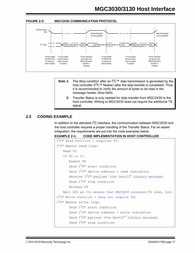
Figure 2-2 shows the complete communication protocol.
TABLE 2-1: USAGE OF TRANSFER STATUS LINE
MGC3X30 Host Controller TS Line Status
Released (H) Released (H) High Host finished reading data (Transfer end). No more data to be transferred to the host. MGC3X30 is allowed to update the data buffer.
Asserted (L) Released (H) Low Data from MGC3X30 is available to be sent, but the host has not yet started reading. If the host is busy and did not start reading before the next data update (5 ms), the MGC3X30 will assert the TS line high while updating the data buffer.
Asserted (L) Asserted (L) Low Host starts reading. MGC3X30 data buffer will not be updated until the end of transfer (host releases TS high).
Released (H) Asserted (L) Low MGC3X30 is ready to update the data buffer, but the host is still read-ing the previous data. MGC3X30 is allowed to update the data only when the host releases the TS high.
DS40001718D-page 16 2013-2015 Microchip Technology Inc.
MGC3030/3130 Host Interface
FIGURE 2-2: MGC3X30 COMMUNICATION PROTOCOL
2.3 CODING EXAMPLE
In addition to the standard I2C interface, the communication between MGC3X30 and the host controller requires a proper handling of the Transfer Status. For an easier integration, the requirements are put into the code examples below.
EXAMPLE 2-1: CODE IMPLEMENTATION IN HOST CONTROLLER
Transfer Status(TS)
I2C™ Bus MGC3130 related Transfer MGC3130 related Transfer
TS line pulled low by master when transfer
is started
TS line released by master and
MGC3130 when transfer is finished
TS line pulled by MGC3130 to request a data transfer
MGC3130 buffer can be updated
Non MGC3130 related transfer or Bus Idle
TS line pulled low by master, when transfer
is started
MGC3130 buffer can be updated
TS line pulled by MGC3130 to request a data transfer
TS line released by master and
MGC3130 when transfer is finished
Note 1: The Stop condition after an I2C™ data transmission is generated by the host controller (I2C™ Master) after the data transfer is completed. Thus, it is recommended to verify the amount of bytes to be read in the message header (Size field).
2: Transfer Status is only needed for data transfer from MGC3X30 to the host controller. Writing to MGC3X30 does not require the additional TS signal.
I2C™ Read Function - requires TS:
I2C™ Master read loop:
Read TS
If TS == 0:
Assert TS
Send I2C™ start condition
Send I2C™ device address + read indication
Receive I2C™ payload (the GestIC® Library message)
Send I2C™ stop condition
Release TS
Wait 200 μs (to assure that MGC3X30 released TS line, too)
I2C™ Write Function - does not require TS:
I2C™ Master write loop:
Send I2C™ start condition
Send I2C™ device address + write indication
Send I2C™ payload (the GestIC® Library message)
Send I2C™ stop condition
2013-2015 Microchip Technology Inc. DS40001718D-page 17
MGC3030/3130 GestIC® Library Interface Description
NOTES:
DS40001718D-page 18 2013-2015 Microchip Technology Inc.

MGC3030/3130 GestIC® LIBRARY
INTERFACE DESCRIPTIONChapter 3. GestIC Library Message Interface
3.1 MESSAGES OVERVIEWGestIC Library messages are defined for providing sensor data to the host application and for controlling MGC3X30 and its embedded features. They are sent as the payload of the I2C packets.
TABLE 3-1: MESSAGES FOR SYSTEM CONTROL
ID Name Page
0x15 System_Status 29
0x06 Request_Message 31
0x83 Fw_Version_Info 32
0xA2 Set_Runtime_Parameter 33
TABLE 3-2: MESSAGE FOR SENSOR DATA OUTPUT
ID Name Page
0x91 Sensor_Data_Output 42
TABLE 3-3: MESSAGES FOR GestIC® LIBRARY UPDATE
ID Name Page
0x80 Fw_Update_Start 46
0x81 Fw_Update_Block 47
0x82 Fw_Update_Completed 49
2013-2015 Microchip Technology Inc. DS40001718D-page 19
MGC3030/3130 GestIC® Library Interface Description
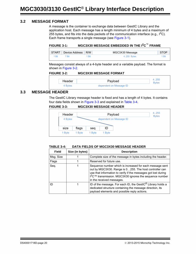
3.2 MESSAGE FORMATA message is the container to exchange data between GestIC Library and the application host. Each message has a length minimum of 4 bytes and a maximum of 255 bytes, and fits into the data packets of the communication interface (e.g., I2C). Each frame transports a single message (see Figure 3-1).
FIGURE 3-1: MGC3X30 MESSAGE EMBEDDED IN THE I2C™ FRAME
Messages consist always of a 4-byte header and a variable payload. The format is shown in Figure 3-2.
FIGURE 3-2: MGC3X30 MESSAGE FORMAT
3.3 MESSAGE HEADER
The GestIC Library message header is fixed and has a length of 4 bytes. It contains four data fields shown in Figure 3-3 and explained in Table 3-4.
FIGURE 3-3: MGC3X30 MESSAGE HEADER
MGC3X30 Message4..255 Bytes
Device AddressSTART STOPR/W7 Bit 1 Bit1 Bit 1 Bit
Header Payload4 Bytes
4..255 Bytes
dependent on Message ID
TABLE 3-4: DATA FIELDS OF MGC3X30 MESSAGE HEADER
Field Size (in bytes) Description
Msg. Size 1 Complete size of the message in bytes including the header.
Flags 1 Reserved for future use.
Seq. 1 Sequence number which is increased for each message sent out by MGC3X30. Range is 0…255. The host controller can use that information to verify if the messages got lost during I2C™ transmission. MGC3X30 ignores the sequence number in the received messages.
ID 1 ID of the message. For each ID, the GestIC® Library holds a dedicated structure containing the message direction, its payload elements and possible reply actions.
size flags
Header
seq
Payload4 Bytes
4..255 Bytes
dependent on Message ID
ID1 Byte 1 Byte 1 Byte 1 Byte
DS40001718D-page 20 2013-2015 Microchip Technology Inc.
GestIC Library Message Interface
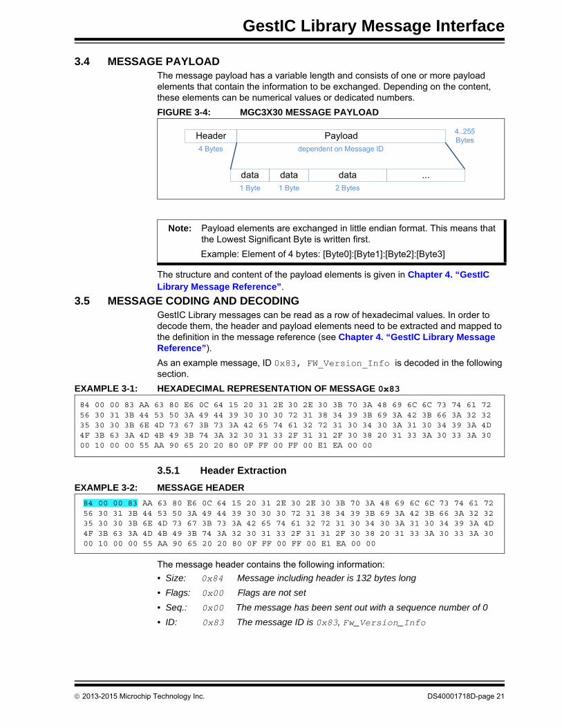
3.4 MESSAGE PAYLOADThe message payload has a variable length and consists of one or more payload elements that contain the information to be exchanged. Depending on the content, these elements can be numerical values or dedicated numbers.
FIGURE 3-4: MGC3X30 MESSAGE PAYLOAD
The structure and content of the payload elements is given in Chapter 4. “GestIC Library Message Reference”.
3.5 MESSAGE CODING AND DECODINGGestIC Library messages can be read as a row of hexadecimal values. In order to decode them, the header and payload elements need to be extracted and mapped to the definition in the message reference (see Chapter 4. “GestIC Library Message Reference”).
As an example message, ID 0x83, FW_Version_Info is decoded in the following section.
EXAMPLE 3-1: HEXADECIMAL REPRESENTATION OF MESSAGE 0x83
3.5.1 Header Extraction
EXAMPLE 3-2: MESSAGE HEADER
The message header contains the following information:
• Size: 0x84 Message including header is 132 bytes long
• Flags: 0x00 Flags are not set
• Seq.: 0x00 The message has been sent out with a sequence number of 0
• ID: 0x83 The message ID is 0x83, Fw_Version_Info
data data
Header
data
Payload4 Bytes
4..255 Bytes
dependent on Message ID
...1 Byte 1 Byte 2 Bytes
Note: Payload elements are exchanged in little endian format. This means that the Lowest Significant Byte is written first.
Example: Element of 4 bytes: [Byte0]:[Byte1]:[Byte2]:[Byte3]
84 00 00 83 AA 63 80 E6 0C 64 15 20 31 2E 30 2E 30 3B 70 3A 48 69 6C 6C 73 74 61 72 56 30 31 3B 44 53 50 3A 49 44 39 30 30 30 72 31 38 34 39 3B 69 3A 42 3B 66 3A 32 32 35 30 30 3B 6E 4D 73 67 3B 73 3A 42 65 74 61 32 72 31 30 34 30 3A 31 30 34 39 3A 4D 4F 3B 63 3A 4D 4B 49 3B 74 3A 32 30 31 33 2F 31 31 2F 30 38 20 31 33 3A 30 33 3A 30 00 10 00 00 55 AA 90 65 20 20 80 0F FF 00 FF 00 E1 EA 00 00
84 00 00 83 AA 63 80 E6 0C 64 15 20 31 2E 30 2E 30 3B 70 3A 48 69 6C 6C 73 74 61 72 56 30 31 3B 44 53 50 3A 49 44 39 30 30 30 72 31 38 34 39 3B 69 3A 42 3B 66 3A 32 32 35 30 30 3B 6E 4D 73 67 3B 73 3A 42 65 74 61 32 72 31 30 34 30 3A 31 30 34 39 3A 4D 4F 3B 63 3A 4D 4B 49 3B 74 3A 32 30 31 33 2F 31 31 2F 30 38 20 31 33 3A 30 33 3A 30 00 10 00 00 55 AA 90 65 20 20 80 0F FF 00 FF 00 E1 EA 00 00
2013-2015 Microchip Technology Inc. DS40001718D-page 21

MGC3030/3130 GestIC® Library Interface Description
3.5.2 Payload Extraction
EXAMPLE 3-3: MESSAGE PAYLOAD
According to Section 4.3 “Fw_Version_Info”, Fw_Version_Info holds seven payload elements:
• FwValid Status of GestIC Library (1 byte)
• HwRev HW revision information (2 bytes)
• ParameterStartAddr Start address of parameter (1 byte)
• LibraryLoaderVersion GestIC Library loader version (2 bytes)
• LibraryLoaderPlatform GestIC Library loader platform (1 byte)
• FwStartAddr Start address of GestIC Library(1 byte)
• FwVersion Version information of GestIC Library if valid (120 bytes)
The values can now be converted and mapped to the description of the payload elements:
FwValid = AA (170): A valid GestIC Library is available
HwRev = 63 80 (read as 0x63 0x80): HW revision is 99.128
ParameterStartAddr = 0xE6 (230x128=29440): Start address of parameter is 29440
LibraryLoaderVersion = 0C 64 (read as 0x64 0x0C): Library Loader version is 100.12
LibraryLoaderPlatform = 15 (read as 0x15): Library Loader Platform is 21
FwStartAddr = 0x20 (32x128=4096): Start address of GestIC Library is 4096
FwVersion = 31 2E 30 2E 30 3B 70 3A 48 69 6C 6C 73 74 61 72 56 30 31 3B 44 53 50 3A 49 44 39 30 30 30 72 31 38 34 39 3B 69 3A 42 3B 66 3A 32 32 35 30 30 3B 6E 4D 73 67 3B 73 3A 42 65 74 61 32 72 31 30 34 30 3A 31 30 34 39 3A 4D 4F 3B 63 3A 4D 4B 49 3B 74 3A 32 30 31 33 2F 31 31 2F 30 38 20 31 33 3A 30 33 3A 30 00 10 00 00 55 AA 90 65 20 20 80 0F FF 00 FF 00 E1 EA 00 00
The version string is interpreted by ASCII characters. It is a semicolon-separated string, always starting with the version number itself, followed by different tags:
1.0.0;p:HillstarV01;DSP:ID9000r1849;i:B;f:22500;nMsg;s:Beta2r1040:1049:MO;c:MKI;t:2013/11/08 13:03:0;...
84 00 00 83 AA 63 80 E6 0C 64 15 20 31 2E 30 2E 30 3B 70 3A 48 69 6C 6C 73 74 61 72 56 30 31 3B 44 53 50 3A 49 44 39 30 30 30 72 31 38 34 39 3B 69 3A 42 3B 66 3A 32 32 35 30 30 3B 6E 4D 73 67 3B 73 3A 42 65 74 61 32 72 31 30 34 30 3A 31 30 34 39 3A 4D 4F 3B 63 3A 4D 4B 49 3B 74 3A 32 30 31 33 2F 31 31 2F 30 38 20 31 33 3A 30 33 3A 30 00 10 00 00 55 AA 90 65 20 20 80 0F FF 00 FF 00 E1 EA 00 00
DS40001718D-page 22 2013-2015 Microchip Technology Inc.

GestIC Library Message Interface
3.6 MESSAGE CONTROL FLOW AND CODING EXAMPLES
3.6.1 Message Control Flow
The control of MGC3X30 GestIC Library is done through the following messages:
• Set_Runtime_Parameter (ID 0xA2)• Request_Message (ID 0x06)
MGC3X30 acknowledges each control message by a System_Status (ID 0x15) which contains the original message ID and a 2-byte error code. If the error code is ‘0’, the message is applied correctly to MGC3X30.
The message control flow from the point of view of the application host is shown in Figure 3-5.
FIGURE 3-5: APPLICATION HOST MESSAGE CONTROL
Start
Send Control Messagee.g. Set_Runtime_Parameter (ID 0xA2)
ErrorCode = 0 ?
Control Message is applied
Receive System_StatusSystem_Status (ID 0x15)
NO
YES
Note: The Hillstar and Sabrewing I2C to USB bridge prefixes every I2C packet with 0xFEFF before it is sent out via UART emulation on USB. That is done to allow a frame separation inside the data stream of the PC. For messages sent to MGC3X30 from a terminal program (e.g., Hterm), the prefix has to be added, as well.
2013-2015 Microchip Technology Inc. DS40001718D-page 23
MGC3030/3130 GestIC® Library Interface Description
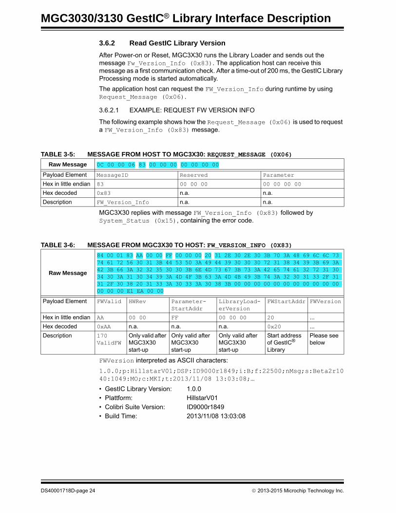
3.6.2 Read GestIC Library Version
After Power-on or Reset, MGC3X30 runs the Library Loader and sends out the message Fw_Version_Info (0x83). The application host can receive this message as a first communication check. After a time-out of 200 ms, the GestIC Library Processing mode is started automatically.
The application host can request the FW_Version_Info during runtime by using Request_Message (0x06).
3.6.2.1 EXAMPLE: REQUEST FW VERSION INFO
The following example shows how the Request_Message (0x06) is used to request a FW_Version_Info (0x83) message.
MGC3X30 replies with message FW_Version_Info (0x83) followed by System_Status (0x15), containing the error code.
FWVersion interpreted as ASCII characters:
1.0.0;p:HillstarV01;DSP:ID9000r1849;i:B;f:22500;nMsg;s:Beta2r1040:1049:MO;c:MKI;t:2013/11/08 13:03:08;…
• GestIC Library Version: 1.0.0• Plattform: HillstarV01
• Colibri Suite Version: ID9000r1849
• Build Time: 2013/11/08 13:03:08
TABLE 3-5: MESSAGE FROM HOST TO MGC3X30: REQUEST_MESSAGE (0X06)
Raw Message 0C 00 00 06 83 00 00 00 00 00 00 00
Payload Element MessageID Reserved Parameter
Hex in little endian 83 00 00 00 00 00 00 00
Hex decoded 0x83 n.a. n.a.
Description FW_Version_Info n.a. n.a.
TABLE 3-6: MESSAGE FROM MGC3X30 TO HOST: FW_VERSION_INFO (0X83)
Raw Message
84 00 01 83 AA 00 00 FF 00 00 00 20 31 2E 30 2E 30 3B 70 3A 48 69 6C 6C 73 74 61 72 56 30 31 3B 44 53 50 3A 49 44 39 30 30 30 72 31 38 34 39 3B 69 3A 42 3B 66 3A 32 32 35 30 30 3B 6E 4D 73 67 3B 73 3A 42 65 74 61 32 72 31 30 34 30 3A 31 30 34 39 3A 4D 4F 3B 63 3A 4D 4B 49 3B 74 3A 32 30 31 33 2F 31 31 2F 30 38 20 31 33 3A 30 33 3A 30 38 3B 00 00 00 00 00 00 00 00 00 00 00 00 00 00 E1 EA 00 00
Payload Element FWValid HWRev Parameter-StartAddr
LibraryLoad-erVersion
FWStartAddr FWVersion
Hex in little endian AA 00 00 FF 00 00 00 20 ...
Hex decoded 0xAA n.a. n.a. n.a. 0x20 ...
Description 170 ValidFW
Only valid after MGC3X30 start-up
Only valid after MGC3X30 start-up
Only valid after MGC3X30 start-up
Start address of GestIC® Library
Please see below
DS40001718D-page 24 2013-2015 Microchip Technology Inc.

GestIC Library Message Interface
3.6.3 Run-Time Control
A dedicated set of run-time control options is provided within the message Set_Runtime_Parameter (0xA2). It can be used to control the active feature set and sensor data output and, thus, it allows the build-up of a context-sensitive operation of MGC3X30. For a detailed message description, please refer to Section 4.4 “Set_Runtime_Parameter”.
The following examples show how to set relevant runtime parameters.
3.6.3.1 EXAMPLE: ENABLE APPROACH DETECTION
This example shows how to enable the Approach Detection mode by using the message Set_Runtime_Parameter (0xA2).
MGC3X30 replies with message System_Status (0x15), containing the error code.
3.6.3.2 EXAMPLE: ENABLE ALL GESTURES
This example shows how to enable all gestures (Flicks and Circles) by using the message Set_Runtime_Parameter (0xA2).
MGC3X30 replies with message System_Status (0x15). Refer to Table 3-8.
TABLE 3-7: MESSAGE FROM HOST TO MGC3X30: SET_RUNTIME_PARAMETER (0XA2)
Raw Message 10 00 00 A2 97 00 00 00 01 00 00 00 01 00 00 00
Payload Element RuntimeParameterID Reserved Argument0 Argument1
Hex in little endian 97 00 00 00 01 00 00 00 01 00 00 00
Hex decoded 0x0097 n.a. 0x00000001 0x00000001
Description ApproachDetection n.a. Enable Approach Detection mode
Mask for Approach Detection bit
TABLE 3-8: MESSAGE FROM MGC3X30 TO HOST: SYSTEM_STATUS (0X15)
Raw Message 10 00 08 15 A2 34 00 00 00 00 00 00 00 00 00 00
Payload Element MsgID MaxCmdSize ErrorCode Reserved Reserved
Hex in little endian A2 34 00 00 00 00 00 00 00 00 00 00
Hex decoded 0xA2 0x34 0x0000 n.a. n.a.
Description Acknowledge to ID 0xA2
n.a. No error n.a. n.a.
TABLE 3-9: MESSAGE FROM HOST TO MGC3X30: SET_RUNTIME_PARAMETER (0XA2)
Raw Message 10 00 00 A2 85 00 00 00 7F 00 00 00 7F 00 00 00
Payload Element RuntimeParameterID Reserved Argument0 Argument1
Hex in little endian 85 00 00 00 7F 00 00 00 7F 00 00 00
Hex decoded 0x0085 n.a. 0x0000007F 0x0000007F
Description despGestureMask n.a. Enable gestures 0...6 Mask for Enable gestures 0...6 bits
2013-2015 Microchip Technology Inc. DS40001718D-page 25
MGC3030/3130 GestIC® Library Interface Description
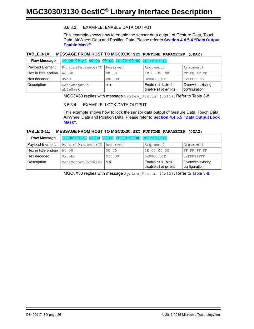
3.6.3.3 EXAMPLE: ENABLE DATA OUTPUT
This example shows how to enable the sensor data output of Gesture Data, Touch Data, AirWheel Data and Position Data. Please refer to Section 4.4.5.4 “Data Output Enable Mask”.
MGC3X30 replies with message System_Status (0x15). Refer to Table 3-8.
3.6.3.4 EXAMPLE: LOCK DATA OUTPUT
This example shows how to lock the sensor data output of Gesture Data, Touch Data, AirWheel Data and Position Data. Please refer to Section 4.4.5.5 “Data Output Lock Mask”.
MGC3X30 replies with message System_Status (0x15). Refer to Table 3-8.
TABLE 3-10: MESSAGE FROM HOST TO MGC3X30: SET_RUNTIME_PARAMETER (0XA2)
Raw Message 10 00 00 A2 A0 00 00 00 1E 00 00 00 FF FF FF FF
Payload Element RuntimeParameterID Reserved Argument0 Argument1
Hex in little endian A0 00 00 00 1E 00 00 00 FF FF FF FF
Hex decoded 0xA0 0x0000 0x0000001E 0xFFFFFFFF
Description DataOutputEn-ableMask
n.a. Enable bit 1...bit 4; disable all other bits
Overwrite existing configuration
TABLE 3-11: MESSAGE FROM HOST TO MGC3X30: SET_RUNTIME_PARAMETER (0XA2)
Raw Message 10 00 00 A2 A1 00 00 00 1E 00 00 00 FF FF FF FF
Payload Element RuntimeParameterID Reserved Argument0 Argument1
Hex in little endian A1 00 00 00 1E 00 00 00 FF FF FF FF
Hex decoded 0x00A1 0x0000 0x0000001E 0xFFFFFFFF
Description DataOutputLockMask n.a. Enable bit 1...bit 4; disable all other bits
Overwrite existing configuration
DS40001718D-page 26 2013-2015 Microchip Technology Inc.

GestIC Library Message Interface
3.6.4 Sensor Data Output
The GestIC Library processes sensor data with a default update rate of 5 ms. That means the I2C message buffer is regularly updated in that time interval. Whenever new data are available, MGC3X30 pulls the TS line to request the I2C master to transfer this data. Sensor data sent from MGC3X30 to the host are included in the message Sensor_Data_Output (0x91).
The content of the sensor data output can be configured via the message Set_Runtime_Parameter (0xA2).
3.6.4.1 EXAMPLE: READ SENSOR DATA OUTPUT
In the following examples the sensor data output is configured according to Section 3.6.3.3 “Example: Enable Data Output” and Section 3.6.3.4 “Example: Lock Data Output”.
TABLE 3-12: MESSAGE FROM MGC3X30 TO HOST: FLICK EAST TO WEST
Raw Message 18 08 FF 91 1E 01 57 8C 03 10 04 00 00 00 00 00 00 00 00 00 00 00 00 00
Payload Element SystemInfo GestureInfo TouchInfo Air-WheelInfo
xyzPosition
Hex in little endian 8C 03 10 04 00 00 00 00 00 00 00 00 00 00 00 00 00
Hex decoded 0x8C 0x00041003 0x00000000 0x0000 0x000000000000
Description Bit 2: RawDataValidBit 3: NoisePowerValidBit 7: DSPRunning
Flick East to West No touch No AirWheel No Position Data available
TABLE 3-13: MESSAGE FROM MGC3X30 TO HOST: TOUCH OF CENTER ELECTRODE
Raw Message 18 08 3B 91 1E 01 38 8D 00 00 00 00 10 00 00 00 00 00 5A A6 12 53 6B 0A
Payload Element SystemInfo GestureInfo TouchInfo Air-WheelInfo
xyzPosition
Hex in little endian 8D 00 00 00 00 10 00 00 00 00 00 5A A6 12 53 6B 0A
Hex decoded 0x8D 0x00000000 0x00000010 0x0000 Byte 1 and 2: 0xA65AByte 3 and 4: 0x5312Byte 5 and 6: 0x0A6B
Description Bit 0: PositionValidBit 2: RawDataValidBit 3: NoisePowerValidBit 7: DSPRunning
No Gesture Detected
Touch on Center Electrode
No AirWheel Data
x: 42586y: 21266z: 2667
TABLE 3-14: MESSAGE FROM MGC3X30 TO HOST: POSITION
Raw Message 18 08 44 91 1E 01 41 8D 00 00 00 00 00 00 00 00 00 00 2F B2 E7 87 6A 35
Payload Element SystemInfo GestureInfo TouchInfo Air-WheelInfo
xyzPosition
Hex in little endian 8D 00 00 00 00 00 00 00 00 00 00 2F B2 E7 87 6A 35
Hex decoded 0x8D 0x00000000 0x00000000 0x0000 Byte 1 and 2: 0xB22FByte 3 and 4: 0x87E7Byte 5 and 6: 0x356a
Description Bit 0: PositionValidBit 2: RawDataValidBit 3: NoisePowerValidBit 7: DSPRunning
No Gesture Detected
Touch on Center Electrode
No AirWheel Data
x: 45615y: 34791z: 13674
2013-2015 Microchip Technology Inc. DS40001718D-page 27

MGC3030/3130 GestIC® Library Interface Description
NOTES:
DS40001718D-page 28 2013-2015 Microchip Technology Inc.

MGC3030/3130 GestIC® LIBRARY
INTERFACE DESCRIPTIONChapter 4. GestIC Library Message Reference
4.1 SYSTEM_STATUS
System_Status is used to acknowledge the reception of messages from the host. This message holds the error code and is used to confirm the transmission of the following messages:
• Request_Message (0x06)• Set_Runtime_Parameter (0xA2)• Fw_Update_Start (0x80)• Fw_Update_Block (0x81)• Fw_Update_Completed (0x82)
Direction: MGC3X30 to Host
TABLE 4-1: MESSAGE OVERVIEW
Header Payload
Msg. Size Flags Seq. ID MsgID MaxCmdSize ErrorCode Reserved Reserved
1 Byte 1 Byte 1 Byte 1 Byte 1 Byte 1 Byte 2 Bytes 4 Bytes 4 Bytes
0x10 n.a. n.a. 0x15 see description below
2013-2015 Microchip Technology Inc. DS40001718D-page 29

MGC3030/3130 GestIC® Library Interface Description
TABLE 4-2: PAYLOAD ELEMENTS
ElementElement Size (in
bytes)Description
MsgID 1 Holds the Message ID which System_Status corresponds toStructure: 1 byteRange: (0x00..0xFF)
MaxCmdSize 1 Holds the maximum I2C™ packet size GestIC® Library accepts (including header)Structure: 1 byteRange: (0..0xFF)
ErrorCode 2 Error code, returned for the previous message.Structure: 16-bit word containing dedicated values (see list below)Possible values:These error codes are sent by the Library Loader, Library Loader Updater and Library0x0000 NoError OK0x0001 UnknownCommand Message ID is unknown
These error codes are sent by the Library Loader0x0002 InvalidSessionId Session ID is invalid or does not match
(0x0 is not allowed) (messageFwUpdateStart, FwUpdateCom-pleted)
0x003 InvalidCrc CRC is invalidthrown by commands:FwUpdateBlock, FwUpdate-Start,FwUpdateCompleted
0x0004 InvalidLength Length is invalid (messageFwUpdateBlock)
0x0005 InvalidAddress Address is invalid (messageFwUpdateBlock)
0x0006 InvalidFunction Function-id is invalid (messageFwUpdateStart, FwUpdateBlock, FwUpdateCompleted)
0x0008 ContentMismatch The VerifyOnly function found a mis-match between content and Flash memory (message: FwUpdateBlock)
0x000B WrongParameterAddr Parameter Start address, contained in the new Library FW to be loaded, does not match Library Loader assumption. The Library Update is therefore aborted. (message: FwUpdateStart)
These error codes are sent by the Library
0x0014 WrongParameterValue The value of the Argument/Parameter of a
RuntimeParameter command is out of the valid range (message: Request Message and Set_Runtime_Parameter)
0x0015 UnknownParameterID The MessageID or RuntimeParameterID is unknown or out of the valid range (message: Request Message and Set_Runtime_Parameter)
0x001A WakeupHappend A wake-up by Host was detected
These error codes are sent by the Library Loader Updater0x0080 LoaderUpdateStarted The Library Loader update started
0x0081 LoaderUpdateFinished The Library Loader update finished
DS40001718D-page 30 2013-2015 Microchip Technology Inc.

GestIC Library Message Reference
4.2 REQUEST_MESSAGE
Request_Message forces GestIC Library to reply to the message with the requested ID.
Direction: Host to MGC3X30
Reserved 4 Reserved
Reserved 4 Reserved
TABLE 4-2: PAYLOAD ELEMENTS
ElementElement Size (in
bytes)Description
TABLE 4-3: MESSAGE OVERVIEW
Header Payload
Msg. Size Flags Seq. ID MessageID Reserved Param.
1 Byte 1 Byte 1 Byte 1 Byte 1 Byte 3 Bytes 4 Bytes
0x0C n.a. n.a. 0x06 see description below
TABLE 4-4: PAYLOAD ELEMENTS
ElementElement Size (in
bytes)Description
MessageID 1 Request the Message with ID MessageID from GestIC® Library. GestIC® Library shall answer with the requested message or stay silent.Structure: Single byte read as a hexadecimal valueRange: (0x00..0xFF)
Reserved 3 Reserved, write as ‘0’.
Param. 4 Optional, parameter can be used to specify the kind of return.Example: Requesting message SetRuntimeParameter, param. specifies the RuntimeParameterId to read-back the parameter.Structure: 32-bit word, containing dedicated values or bit fields.Range: (0x00000000..0xFFFFFFFF)
Note 1: The Request_Message command can only be used with MessageID 0x83 and 0xA2.
2: The TransFreqSelect runtime parameter is a write only parameter and could not be requested with message Request_Message.
3: For the complete list of the Request_Message command examples please refer to Table A-1.
2013-2015 Microchip Technology Inc. DS40001718D-page 31

MGC3030/3130 GestIC® Library Interface Description
4.3 FW_VERSION_INFO
At start-up, MGC3X30 sends Fw_Version_Info message to the host interface to
show that the chip is alive and ready for operation. Fw_Version_Info can also be
requested using Request_Message (0x06).
Direction: MGC3X30 to Host.
Note: The payload elements HWRev, ParameterStartAddr and LibraryLoaderVersion are only valid after MGC3X30 start-up.
TABLE 4-5: MESSAGE OVERVIEW
Header Payload
Msg. Size
Flags Seq. ID FwValid HwRev ParameterStartAddr LibraryLoaderVersion FwStartAddr FwVersion
1 Byte 1 Byte 1 Byte 1 Byte 1 Byte 2 Bytes 1 Byte 3 Bytes 1 Byte 120 Bytes
0x84 n.a. n.a. 0x83 see description below
TABLE 4-6: PAYLOAD ELEMENTS
ElementElement Size
(in bytes)Description
FwValid 1 Status of GestIC® Library.Structure: Single byte containing dedicated values (see list below)Possible values:0x00 Empty No valid GestIC® Library could be located0x0A InvalidFW An invalid GestIC® Library was stored, or the last
update failed0xAA ValidFW A valid GestIC® Library is available
HwRev 2 Hardware revision informationStructure: Vector of 2 bytes interpreted as decimal values in format xx.xxRange: (0x00..0xFF, 0x00..0xFF)
ParameterStartAddr 1 Parameter start address as supported by the Imageaddress = 128 * value of ParameterStartAddrStructure: 1 byte interpreted as hex valueRange: (0x00..0xFF)
LibraryLoaderVersion 3 GestIC® Library loader version informationStructure: Vector of 3 bytes interpreted as decimal values in format
xx.xx.xxRange: (0x00..0xFF, 0x00..0xFF,0x00..0xFF)
FwStartAddr 1 Start address of GestIC® Library as supported by the Bootloader, start address = 128 * value of FwStartAddrStructure: 1 byte interpreted as hex valueRange: (0x00..0xFF)
FwVersion 120 Version information of GestIC® Library if valid (FwValid is not 0x00). The version string is interpreted as ASCII characters. It is a semicolon-separated string, always starting with the Version Number itself, followed by different tags.Supported Tags:p Platform (e.g., HillstarVxx)DSP Colibri Suite Version (e.g., ID45r -1167)s Reservedc Reservedt Build time (e.g., 2013/04/24 14:24:50)Structure: Vector of 120 bytes interpreted as string (ASCII characters)Range: (0x00..0xFF, 0x00..0xFF, 0x00..0xFF, ...)
DS40001718D-page 32 2013-2015 Microchip Technology Inc.

GestIC Library Message Reference
4.4 SET_RUNTIME_PARAMETER
This message is used to set runtime parameters within the GestIC Library. It supports parameters for AFE parameterization, feature configuration and sensor data output. A special value is defined for a persistent saving of parameters to the Flash memory. Parameters which can be made persistent are grouped into three categories:
• Analog Front End (AFE) Category
• Digital Signal Processing (DSP) Category
• System Category
Direction: Host to MGC3X30.
4.4.1 Trigger
This parameter forces a trigger defined in Argument0.
RuntimeParameterID 0x1000 Trigger Parameter forces a trigger.
Argument0 0x00000000: Force recalibration
0x00000002: Enter Deep Sleep 1: The wake-up sources from Deep Sleep 1 are I2C0 Start bit detection or MCLR Reset. The system will resume from Deep Sleep on any I2C messages sent on the bus and the first I2C message will be lost.
0x00000003: Enter Deep Sleep 2: The wake-up source from Deep Sleep 2 is a falling edge on External Interrupt (IRQ0) or MCLR Reset. The IRQ0 (EIO2) should be tied to high when this command is sent unless the MGC3X30 will resume directly after receiving it.
Range: (0x00000000, 0x00000002, 0x00000003)
Argument1 Not used
TABLE 4-7: MESSAGE OVERVIEW
Header Payload
Msg. Size Flags Seq. ID RuntimeParameterID Reserved Argument0 Argument1
1 Byte 1 Byte 1 Byte 1 Byte 2 Bytes 2 Bytes 4 Bytes 4 Bytes
0x10 n.a. n.a. 0xA2 see description below
TABLE 4-8: PAYLOAD ELEMENTS
ElementElement Size
(in bytes)Description
RuntimeParameterID 2 ID of runtime parameter. Please refer to Section 4.4.1 “Trigger” through Section 4.4.5.5 “Data Output Lock Mask”.Structure: 16-bit word interpreted as hex valueRange: (0x0000..0xFFFF)
Reserved 2 write as ‘0’
Argument0 4 Argument values, depending on runtime parameter ID. If not used, Argument0 should be provided as ‘0’.Structure: 32-bit word: Argument0Range: depends on runtime parameter
Argument1 4 Argument values, depending on runtime parameter ID. If not used, Argument1 should be provided as ‘0’.Structure: 32-bit word: Argument1.Range: depends on runtime parameter.
2013-2015 Microchip Technology Inc. DS40001718D-page 33
MGC3030/3130 GestIC® Library Interface Description
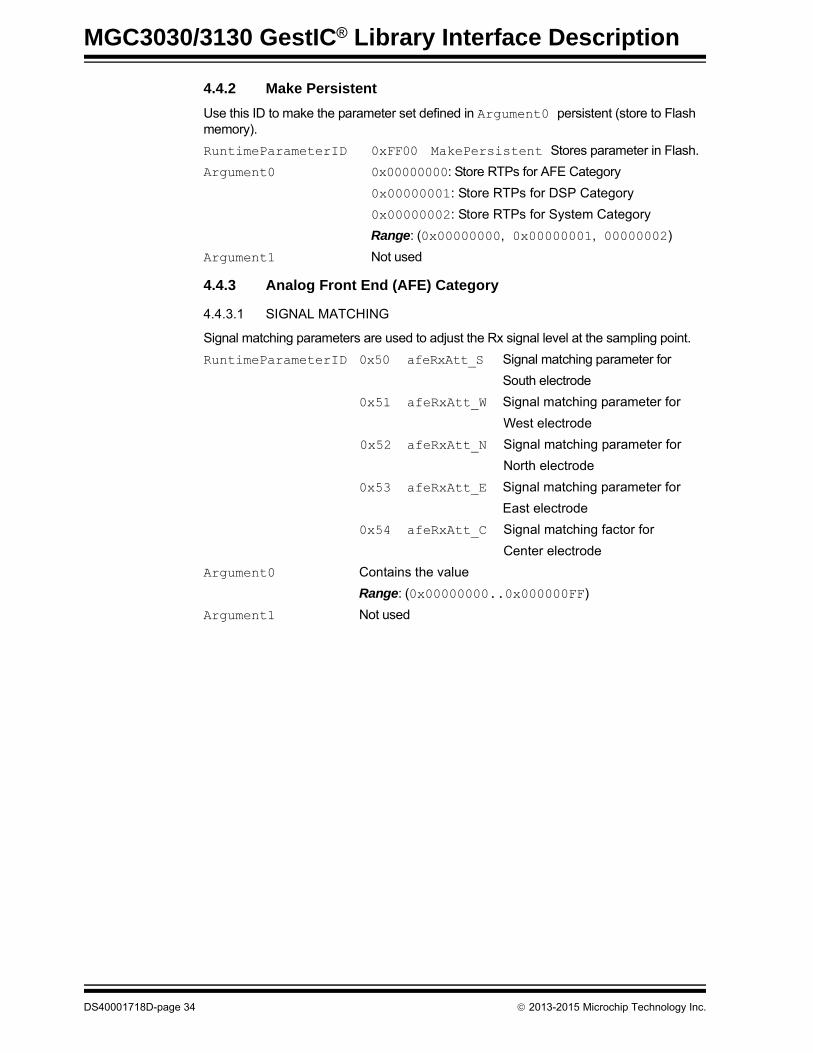
4.4.2 Make Persistent
Use this ID to make the parameter set defined in Argument0 persistent (store to Flash memory).
RuntimeParameterID 0xFF00 MakePersistent Stores parameter in Flash.
Argument0 0x00000000: Store RTPs for AFE Category
0x00000001: Store RTPs for DSP Category
0x00000002: Store RTPs for System Category
Range: (0x00000000, 0x00000001, 00000002)
Argument1 Not used
4.4.3 Analog Front End (AFE) Category
4.4.3.1 SIGNAL MATCHING
Signal matching parameters are used to adjust the Rx signal level at the sampling point.
RuntimeParameterID 0x50 afeRxAtt_S Signal matching parameter for
South electrode
0x51 afeRxAtt_W Signal matching parameter for
West electrode
0x52 afeRxAtt_N Signal matching parameter for
North electrode
0x53 afeRxAtt_E Signal matching parameter for
East electrode
0x54 afeRxAtt_C Signal matching factor for
Center electrode
Argument0 Contains the value
Range: (0x00000000..0x000000FF)
Argument1 Not used
DS40001718D-page 34 2013-2015 Microchip Technology Inc.

GestIC Library Message Reference
4.4.3.2 ELECTRODE MAPPING
The physical channel number assigned to the electrodes. These parameters represent the physical connection of the electrodes to MGC3X30 Rx channels. For the correct function, the mapping has to be looked up in the circuitry design.
RuntimeParameterID 0x65 Channelmapping_S Physical channel assigned
to the South Electrode
0x66 Channelmapping_W Physical channel assigned
to the West Electrode
0x67 Channelmapping_N Physical channel assigned
to the North Electrode
0x68 Channelmapping_E Physical channel assigned
to the East Electrode
0x69 Channelmapping_C Physical channel assigned
to the Center Electrode
Argument0 Contains the number of physical receive channels (Rx0, Rx1, Rx2, Rx3, Rx4)
Range: (0x00000000, 0x00000001, 0x00000002, 0x00000003, 0x00000004)
Argument1 Not used.
2013-2015 Microchip Technology Inc. DS40001718D-page 35

MGC3030/3130 GestIC® Library Interface Description
4.4.4 Digital Signal Processing (DSP) Category
4.4.4.1 TRANSMIT FREQUENCY SELECTION
Sets the amount of used transmitter frequencies and the order in which they are tested for the frequency hopping.
RuntimeParameterID 0x82 TransFreqSelect Parameter to set the used frequencies IDs
Argument0 Amount of used Tx frequencies. This parameter can be 1, 2, 3, 4 or 5.
Argument1 This determines in what order the transmitter frequencies are tested. The indexes numbered 0 to 4 represent respective transmitter frequencies:
- Frequency ID 0 corresponds to 115 kHz
- Frequency ID 1 corresponds to 103 kHz
- Frequency ID 2 corresponds to 88 kHz- Frequency ID 3 corresponds to 67 kHz
- Frequency ID 4 corresponds to 44 kHz
These indexes have to be provided in nibbles.
Example: e.g., Argument0 = 0x04 in combination with
Argument1 = 0x3104 means that frequencies with the index 4, 0, 1 and 3 are used and tested in this specific order.
e.g., Index – Default Frequency Mapping (Argument 0 = 0x5, Argument 1 = 0x43210)
Frequency ID 0 – Transmitter Frequency: 115 kHz
Frequency ID 1 – Transmitter Frequency: 103 kHz
Frequency ID 2 – Transmitter Frequency: 88 kHz
Frequency ID 3 – Transmitter Frequency: 67 kHz
Frequency ID 4 – Transmitter Frequency: 44 kHz
Note: The TransFreqSelect runtime parameter is a write-only parameter and could not be requested with message REQUEST_MESSAGE (0x06).
DS40001718D-page 36 2013-2015 Microchip Technology Inc.

GestIC Library Message Reference
4.4.4.2 TOUCH DETECTION
This parameter enables/disables Touch Detection.
RuntimeParameterID 0x97 dspTouchConfig Parameter to enable/disable Touch Detection
Argument0 Set Argument0 to ‘0x08’ to enable and set Argument0 to
‘0x00’ to disable Touch Detection
Note: If Argument1 is not set correctly the system will show malfunctions.
Argument1 0x08
4.4.4.3 APPROACH DETECTION
This parameter enables/disables Approach Detection mode.
RuntimeParameterID 0x97dspApproachDetectionMode Parameter to enable/ disable Approach Detection Mode
Argument0 Set Argument0 to 0x01 to enable and set Argument0 to
0x00 to disable Approach Detection
Note: If Argument1 is not set correctly the system will show malfunctions.
Argument1 0x01
Note: On earlier versions than V1.0, the Approach Detection RuntimeParame-terID was 0x81 with the same definition of Argument0 and Argument1. This RTC is no longer supported on V1.1 and later. Aurea PC Software still uses this RTC for legacy purposes.
2013-2015 Microchip Technology Inc. DS40001718D-page 37

MGC3030/3130 GestIC® Library Interface Description
4.4.5 System Category
4.4.5.1 AIRWHEEL
This parameter enables/disables AirWheel.
RuntimeParameterID 0x90 dspAirWheelConfig Parameter to enable/disable AirWheel
Argument0 Set Argument0 to ‘0x20’ to enable and set Argument0 to ‘0x00’ to disable AirWheel
Note: If Argument1 is not set correctly the system will show malfunctions.
Argument1 0x20
4.4.5.2 GESTURE PROCESSING (HMM)
This parameter enables the in-built gestures. Disabling one gesture will increase the recognition probability of the others.
If a bit in Argument0 is set to ‘1’, the respective Gesture will be enabled. If a bit in Argument0 is set to ‘0’, the respective Gesture will be disabled.
RuntimeParameterID 0x85 dspGestureMask Parameter to enable/disable gestures
Argument0 Bit 0: Garbage model
Bit 1: Flick West to East
Bit 2: Flick East to West
Bit 3: Flick South to North
Bit 4: Flick North to South
Bit 5: Circle clockwise
Bit 6: Circle counter-clockwise
Argument1 Acts as a mask, set appropriate bits to ‘1’ to change the flag. All other flags are kept unchanged.
4.4.5.3 CALIBRATION OPERATION MODE
This parameter enables/disables the selected auto-calibration feature.
If a bit in Argument0 is set to ‘0’, the respective auto-calibration feature will be enabled.
If a bit in Argument0 is set to ‘1’ the respective auto-calibration feature will be disabled.
RuntimeParameterID 0x80 dspCalOpMode Parameter to enable/disable auto-calibration
Argument0 Bit 0: Enable/disable start-up calibration
Bit 1: Enable/disable gesture-triggered calibration
Bit 2: Enable/disable negative calibration
Bit 3: Enable/disable idle calibration
Bit 4: Enable/disable invalidity value calibration, if values are completely out of range
Bit 5: Enable/disable calibration triggered by AFA
Argument1 Acts as a mask, set appropriate bits to ‘1’ to change the flag.
All other flags are kept unchanged.
DS40001718D-page 38 2013-2015 Microchip Technology Inc.

GestIC Library Message Reference
4.4.5.4 DATA OUTPUT ENABLE MASK
This parameter determines the data output of the message Sensor_Data_Output (0x91). If a bit in Argument0 is set to ‘1’, the respective payload element will be part
of the message Sensor_Data_Output (0x91). If a bit in Argument0 is set to ‘0’,
the payload element will not be part of the message Sensor_Data_Output (0x91).
Use DataOutputEnableMask to optimize the sensor data output in terms of I2C utilization and efficiency of the host code.
Please mind that enabling all payload elements might lead to malfunctions due to bandwidth limitations on the I2C bus.
RuntimeParameterID 0xA0 DataOutputEnableMask Parameter determining the data output.
Argument0 Bit 0: DSP Status
Bit 1: Gesture Data
Bit 2: Touch Data
Bit 3: AirWheel Data
Bit 4: Position Data
Bit 5: Noise Power
Bits 6...10: These bits are reserved and must be set to ‘0’.
Bit 11: Uncalibrated Signal (CIC) Data.
Bit 12: Signal Deviation (SD) Data.
Bits 13...15: These bits are reserved and must be set to ‘0’.
Argument1 Acts as a mask, set appropriate bits to ‘1’ to change the flag.
All other flags are kept unchanged.
2013-2015 Microchip Technology Inc. DS40001718D-page 39
MGC3030/3130 GestIC® Library Interface Description
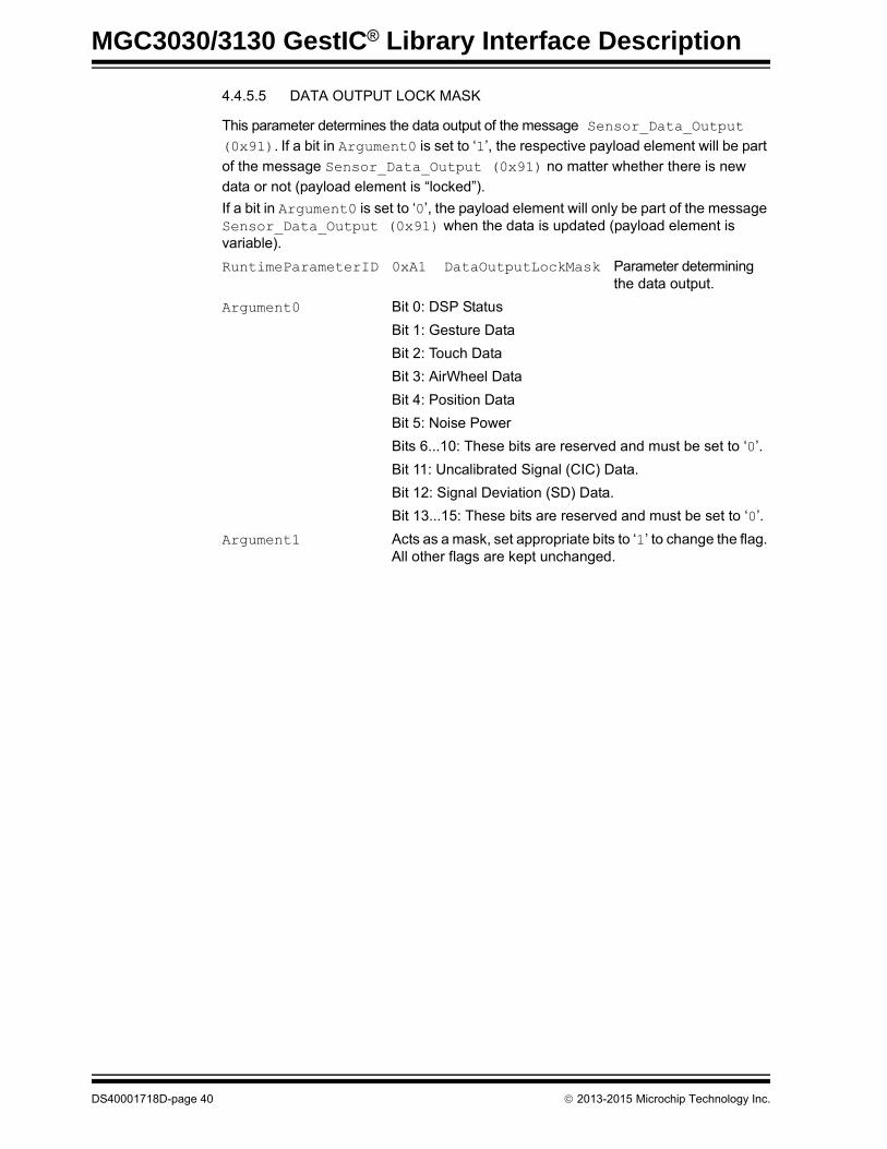
4.4.5.5 DATA OUTPUT LOCK MASK
This parameter determines the data output of the message Sensor_Data_Output (0x91). If a bit in Argument0 is set to ‘1’, the respective payload element will be part
of the message Sensor_Data_Output (0x91) no matter whether there is new
data or not (payload element is “locked”).
If a bit in Argument0 is set to ‘0’, the payload element will only be part of the message Sensor_Data_Output (0x91) when the data is updated (payload element is variable).
RuntimeParameterID 0xA1 DataOutputLockMask Parameter determining the data output.
Argument0 Bit 0: DSP Status
Bit 1: Gesture Data
Bit 2: Touch Data
Bit 3: AirWheel Data
Bit 4: Position Data
Bit 5: Noise Power
Bits 6...10: These bits are reserved and must be set to ‘0’.
Bit 11: Uncalibrated Signal (CIC) Data.
Bit 12: Signal Deviation (SD) Data.
Bit 13...15: These bits are reserved and must be set to ‘0’.
Argument1 Acts as a mask, set appropriate bits to ‘1’ to change the flag. All other flags are kept unchanged.
DS40001718D-page 40 2013-2015 Microchip Technology Inc.

GestIC Library Message Reference
4.4.5.6 DATA OUTPUT REQUEST MASK
This parameter determines the data output only of the next message Sensor_Data_Output (0x91). If a bit in Argument0 is set to ‘1’, the respective payload element will be part of the next message Sensor_Data_Output (0x91).
If a bit in Argument0 is set to ‘0’, the payload element will not be part of the next message Sensor_Data_Output (0x91) when the data is updated.
This will force the MGC3X30 to send a new message Sensor_Data_Output (0x91) even if there were no valid events and data. This message will contain data according to the Argument0 selection. Then the Sensor_Data_Output (0x91) will be sent according to the Data Output Enable and Lock masks only on valid events and data.
RuntimeParameterID 0xA2 DataOutputRequestMask Parameter determining the next data output.
Argument0 Bit 0: DSP Status
Bit 1: Gesture Data
Bit 2: Touch Data
Bit 3: AirWheel Data
Bit 4: Position Data
Bit 5: Noise Power
Bits 6...10: These bits are reserved and must be set to ‘0’.
Bit 11: Uncalibrated Signal (CIC) Data.
Bit 12: Signal Deviation (SD) Data.
Bit 13...15: These bits are reserved and must be set to ‘0’.
Argument1 Acts as a mask, set appropriate bits to ‘1’ to change the flag. All other flags are kept unchanged.
4.4.5.7 GESTURE IN PROGRESS FLAG CONTROL
This parameter determines whether the gesture in progress output will be part of the GestureInfo data output of the message Sensor_Data_Output (0x91). If Argument0 is set to 0x1, the gesture in progress will be output in the GestureInfo field (bit 31) from the message Sensor_Data_Output (0x91).
If Argument0 is set to 0x0, the gesture in progress will not be output in the GestureInfo field (bit 31) from the message Sensor_Data_Output (0x91).
For more details please refer to Section 4.5 “Sensor_Data_Output”.
RuntimeParameterID 0xA3 DataOutputGestureInProgress
Parameter enabling or disabling the gesture in progress output in the GestureInfo field.
Argument0 0x00000000: Gesture in progress output disabled
0x00000001: Gesture in progress output enabled
Argument1: 0x00000001
Note: For the complete list of the Set_Runtime_Parameter command examples please refer to Table A-2.
2013-2015 Microchip Technology Inc. DS40001718D-page 41

MGC3030/3130 GestIC® Library Interface Description
4.5 SENSOR_DATA_OUTPUT
This message contains the sensor data output of the MGC3X30. The content of the message can be configured via bit mask (refer to DataOutputEnableMask and DataOutputLockMask in Section 4.4 “Set_Runtime_Parameter”).
The elements DataOutputConfigMask, TimeStamp and SystemInfo are always part of the message. The inclusion of further payload elements depends on the configuration and the actual configuration can be read from the payload element DataOutputConfigMask.
Direction: MGC3X30 to Host
TABLE 4-9: MESSAGE OVERVIEW
Header Payload
Size Flags Seq. ID DataOutputConfigMask TimeStamp SystemInfo Variable Depending on DataOutputConfigMask
1 Byte 1 Byte 1 Byte 1 Byte 2 Bytes 1 Byte 1 Byte Variable Depending on DataOutputConfigMask
variable n.a. n.a. 0x91 see description below
TABLE 4-10: PAYLOAD ELEMENTS
ElementElement size
(in bytes)Description
DataOutputConfig-Mask
2 Bit mask indicating which data is part of the message.The following bits are used:
Bit 0: DSPStatus field.Bit 1: GestureInfo field.Bit 2: TouchInfo field.Bit 3: AirWheelInfo field.Bit 4: xyzPosition field.Bit 5: NoisePower field.Bit 6: This bit is reserved.Bit 7: This bit is reserved.Bit 8...10: ElectrodeConfiguration
000: ChCnt = 4, four electrode configuration w/o Center electrode001: ChCnt = 5, five electrode configuration with Center electrode
Bit 11: CICData field with chCnt entries.Bit 12: SDData field with chCnt entries.Bit 13...15: These bits are reserved.
Structure: 16-bit word read as a bit mask.Range: (0x0000..0xFFFF)
TimeStamp 1 8-Bit Counter of 200 Hz (Sample Interval)200 Hz counter value wraps around after 256 ticks. This indicates when an event has taken place and allows measuring the elapsed time between two events as long as it is below approximately 1.25 seconds.Structure: 8-bit word read as decimal value.Range: (0x00..0xFF)
SystemInfo 1 Bit mask indicating if the respective sensor data is valid. In an application, the sensor data output should only be further processed if the respective bits are set to ‘1’.The following bits are used:
Bit 0: PositionValid, if set indicates that the position in the xyzPosition field is valid.Bit 1: AirWheelValid, if set indicates that the AirWheel is active and the data in the
AirWheelInfo field is valid.Bit 2: RawDataValid, if set indicates that the data of the CICData and SDData fields are
valid. Otherwise those fields must be ignored.Bit 3: NoisePowerValid, if set indicates that the NoisePower field is valid.Bit 4: EnvironmentalNoise, if set indicates that environmental noise has been detected.Bit 5: Clipping, if set indicates that the ADCs are clipping.Bit 6: This bit is reserved.Bit 7: DSPRunning, if set indicates that the system is currently running. If not set, the system is
about to go to sleep.Structure: 8-bit word read as a bit mask.Range: (0x00..0xFF)
Note: Position Data is disabled from the sensor data output and AirWheel is enabled: Position Valid will be set and sent with SystemInfo and a new message will be sent when AirWheel detection starts.
DS40001718D-page 42 2013-2015 Microchip Technology Inc.

GestIC Library Message Reference
DSPStatus 2 This element consists of two bytes. The first byte contains information about calibration events. The second byte indicates the Tx frequency currently used.
Bit 0: This bit is reserved.Bit 1: CalibrationInfo: Forced calibration (by Host)Bit 2: CalibrationInfo: Start-up calibrationBit 3: CalibrationInfo: Gesture triggeredBit 4: CalibrationInfo: Negative valueBit 5: CalibrationInfo: Idle calibrationBit 6: CalibrationInfo: Invalid value calibrationBit 7: CalibrationInfo: calibration triggered by AFABits 8…15: Tx Frequency in kHz gesture as decimal value (44..115)
Structure: 2 bytes, first byte read as a bit mask second byte as decimal.Range: (0x00..0xFF; 44..115)
GestureInfo 4 This field contains the 32-bit gesture information word.Recognized Gestures:The recognized gestures are results of the HMM classification. Edge detection can be used to further classify where the gesture has been done (Edge Flicks). Furthermore, gesture attributes give information about the direction of the flick. The gesture information is given as a bit field and can be decoded as follows:
Bits 0...7: Recognized gesture as decimal number0: No gesture1: Garbage model2: Flick West to East3: Flick East to West4: Flick South to North5: Flick North to South6: Circle clockwise (only active if AirWheel disabled)7: Circle counter-clockwise (only active if AirWheel disabled)
Bits 8...11: These bits must not be interpreted.Bits 12…15: Gesture Class read as a decimal number
0: Garbage model1: Flick gesture2: Circular gesture
Bit 16: Edge flick – is 1 if flick gesture is classified as edge flickBits 17...30: These bits are reserved.Bit 31: Gesture recognition in progress. This bit is set when the Gesture Recognizer is
active and reset when the gesture is recognized and the Recognizer is off.0: Gesture recognition not in progress1: Gesture recognition in progress
Structure: 32-bit word read as a bit maskRange: (0x00000000..0xFFFFFFFF)
TouchInfo 4 Contains touch informationThe following bits are used to indicate a touch event on the respective electrodes:
Bit 0: Touch South electrodeBit 1: Touch West electrodeBit 2: Touch North electrodeBit 3: Touch East electrodeBit 4: Touch Center electrodeBit 5: Tap South electrodeBit 6: Tap West electrodeBit 7: Tap North electrodeBit 8: Tap East electrodeBit 9: Tap Center electrodeBit 10: Double Tap South electrodeBit 11: Double Tap West electrodeBit 12: Double Tap North electrodeBit 13: Double Tap East electrodeBit 14: Double Tap Center electrodeBit 15: This bit is reserved.Bits 16...23: Touch Counter: 8-bit counter. This counter determines the period between the time
when the hand starts moving to touch until it is detected. This period is equal to [Touch Counter Value] x 5 (ms). The counter starts counting when the minimum approach speed required to detect a touch event is exceeded until the touch is detected. After each touch detection, the counter is reset.
Bits 24...31: These bits are reserved.Structure: 32-bit word read as a bit maskRange: (0x00000000xx0xFFFFFFFF)
AirWheelInfo 2 The first byte contains a counter which indicates how far the AirWheel rotation has progressed. Incrementing values indicate a clockwise rotation. Decrementing values indicate counter clockwise rotation. An increment of 32 approximates one full rotation. AirWheelInfo is only valid if the AirWheelValid bit in the element SystemInfo is ‘1’.The second byte is reserved.Structure: Vector of two 8-bit words read as a decimal valueRange: (0x0000..0x00FF)
TABLE 4-10: PAYLOAD ELEMENTS (CONTINUED)
ElementElement size
(in bytes)Description
2013-2015 Microchip Technology Inc. DS40001718D-page 43

MGC3030/3130 GestIC® Library Interface Description
xyzPosition 6 This element contains x, y and z position data. Two bytes are used for each of the positions x, y and z.Bytes 1 and 2: x positionBytes 3 and 4: y positionBytes 5 and 6: z position
The position information is only valid if the PositionValid bit in the element SystemInfo is ‘1’. The data give the position of the user’s hand in the Cartesian coordinate system. Position data of [0,0,0] represent the origin of the coordinate system and data of [65535, 65535, 65535] are the maximum dimension of the sensing space. The origin is defined as the lower left corner of the sensitive space (South-West) at the surface of the system.Structure: Vector of three16-bit words read as a decimal value for each position x, y, zRange: (0x0000..0xFFFF) for each position x, y, z
NoisePower 4 Noise Power of the GestIC® system.NoisePower is only valid if the NoisePowerValid bit in the element SystemInfo is '1'.Structure: 32-bit word read as a float valueRange: (0..3.402823e+38)
CICData 4xChCnt Uncalibrated Sensor Data (CIC Data)Element size depends on ChCnt indicated in payload element DataOutputConfigMask bits 8...10.CICData are only valid if the RawDataValid bit in the element SystemInfo is '1'.Structure: Vector of four, respectively five, 32-bit words interpreted as float values in format xxxx.xxxx.xxxx.xxxx.xxxx (South.West.North.East.Center)Range: (-3.402823e+38..3.402823e+38) for each channel
SDData 4xChCnt Signal Deviation (SD)Element size depends on ChCnt indicated in payload element DataOutputConfigMask bits 8...10.SDData are only valid if the RawDataValid bit in the element SystemInfo is '1'.Structure: Vector of four, respectively five, 32-bit words interpreted as float values in format xxxx.xxxx.xxxx.xxxx.xxxx (South.West.North.East.Center)Range: (-3.402823e+38...3.402823e+38) for each channel
Reserved — Reserved: Additional payload elements can be added in the future or for debug purposes.
TABLE 4-10: PAYLOAD ELEMENTS (CONTINUED)
ElementElement size
(in bytes)Description
Note: For the examples list of the Sensor_Data_Output command please refer to Table A-3.
DS40001718D-page 44 2013-2015 Microchip Technology Inc.

MGC3030/3130 GestIC® LIBRARY
INTERFACE DESCRIPTIONChapter 5. Messages for GestIC Library Update
5.1 LIBRARY LOADER UPDATE PROCEDUREThe general library update process is shown in Figure 5-1. Please note that only libraries provided by Microchip Technology can be updated on the MGC3X30. Further-more, an Application Note which describes the library update process in detail can be delivered by Microchip by request only.
For the library update process, three different messages are required:
- Fw_Update_Start (Message ID – 0x80)- Fw_Update_Block (Message ID – 0x81)
- Fw_Update_Completed (Message ID – 0x82)
FIGURE 5-1: LIBRARY UPDATE FLOWCHART
Start GestIC® Library Update with message
Fw_Update_Start
Update one block (up to 1 Flash page) with message
Fw_Update_Block
Update another block?
No
Yes
Reset MGC3130, e.g., with message
Fw_Update_Completed (UpdateFunction ‚Reset‘) or
hardware Reset
Flash Library version with message
Fw_Update_Completed
2013-2015 Microchip Technology Inc. DS40001718D-page 45

MGC3030/3130 GestIC® Library Interface Description
5.2 FW_UPDATE_START
This message starts the update session of the MGC3X30 device.
Direction: Host to MGC3X30
TABLE 5-1: MESSAGE OVERVIEW
Header Payload
Msg. Size Flags Seq. ID Crc SessionID IV UpdateFunction Reserved
1 Byte 1 Byte 1 Byte 1 Byte 4 Bytes 4 Bytes 14 Bytes 1 Byte 1 Byte
0x1C n.a. n.a. 0x80 see description below
TABLE 5-2: PAYLOAD ELEMENTS
FieldSize
(in bytes)Description
Crc 4 A CRC32 (Ethernet, polynomial: 0x04C11DB7) calculated across the rest of the message (20 bytes)Structure: 32-bit wordRange: (0x00000000..0xffffffff)
SessionId 4 The SessionID is a random number generated by the Host. It has to be resent in the Fw_Update_Completed message or else the session will be invalid. 0x00000000 is an invalid SessionID and is used to force the device in a wait loop. In this case, the remaining information in this message is discarded. Structure: 32-bit wordRange: (0x00000000..0xffffffff)
IV 14 14-byte value which is used to encrypt the data.Structure: Vector of 14 bytesRange: (0x00..0xFF, 0x00..0xFF, 0x00..0xFF, ...)
UpdateFunction 1 The UpdateFunction sets the mode of the whole update session:- If the Session mode is set ProgramFlash, the Payloads of the
following Fw_Update_Block messages are written to Flash. - If the Session mode is set VerifyOnly, the code is only verified
(comparison between Flash content and decrypted payload of Fw_Update_Block messages), but not written to Flash. If a mismatch between decrypted payload and Flash is found, a System_Status message with an Error 8 (ContentMismatch) is returned
Note: The following Fw_Update_Block messages also contain an UpdateFunction field. That field defines the mode for the single Update Blocks.
However:- if the mode of the session is set to ProgramFlash via Fw_Up-date_Start, the UpdateFunction of the single Fw_Update_-Blocks can be set to ProgramFlash or to VerifyOnly.
- if the mode of the session is set to VerifyOnly via Fw_Up-date_Start, the UpdateFunction of the single Fw_Update_-Blocks can only be set to VerifyOnly.
Structure: Single byte containing dedicated values (see list below)Possible values:0 Program Flash1 VerifyOnly
Reserved 1 Reserved
DS40001718D-page 46 2013-2015 Microchip Technology Inc.
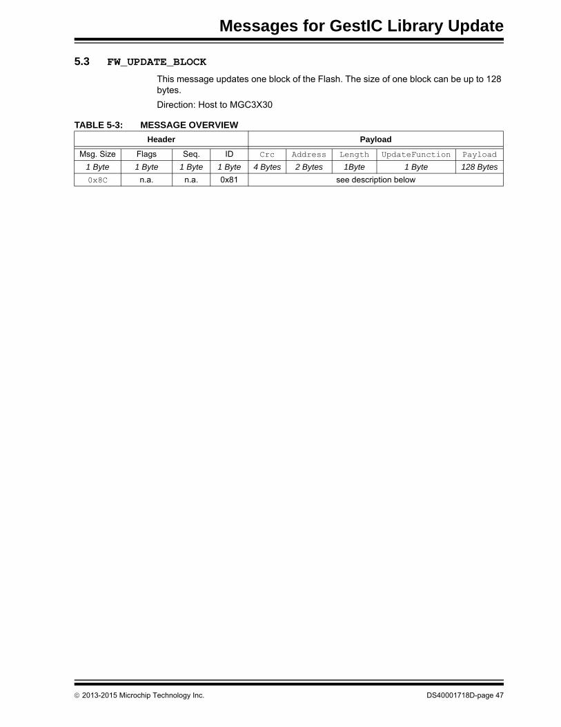
Messages for GestIC Library Update
5.3 FW_UPDATE_BLOCK
This message updates one block of the Flash. The size of one block can be up to 128 bytes.
Direction: Host to MGC3X30
TABLE 5-3: MESSAGE OVERVIEW
Header Payload
Msg. Size Flags Seq. ID Crc Address Length UpdateFunction Payload
1 Byte 1 Byte 1 Byte 1 Byte 4 Bytes 2 Bytes 1Byte 1 Byte 128 Bytes
0x8C n.a. n.a. 0x81 see description below
2013-2015 Microchip Technology Inc. DS40001718D-page 47

MGC3030/3130 GestIC® Library Interface Description
TABLE 5-4: PAYLOAD ELEMENTS
Field Size (in bytes) Description
Crc 4 CRC32 (Ethernet, polynomial: 0x04C11DB7) value, calculated across the rest of the message (132 bytes)Structure: 32-bit wordRange: (0x00000000..0xffffffff)
Address 2 The Flash address of the block which will be programmed/verified. If the block is smaller than 128 bytes, it has to be aligned at the end of each page. So, if the next update block is a full 128-byte block, it can be Flash-page aligned again.
Note: The lower 4 KB are reserved for the Library Loader and cannot be updated. If a value lower than the 4 KB is used, a System_Status message with the Error 5 (InvalidAddress) is returned.
Structure: 16-bit wordRange: (0x1000..0x7fff)
Length 1 The length of the content of the block which will be updated:Structure: Single byteRange: (0x00..0x80)
UpdateFunction 1 The UpdateFunction sets the mode for this single Update Block.
- If the mode is set ProgramFlash, the decrypted Payload is written to Flash.
- If the Session mode is set VerifyOnly, the code is only verified (comparison between Flash content and decrypted payload, but not written to Flash. If a mis-match between decrypted payload and Flash is found, a System_Status message with Error 8 (ContentMismatch) is returned.
Note: If the mode of the whole session was set to VerifyOnly in the Fw_Update_Start message, only VerifyOnly can be set in the Fw_Update_-Block; otherwise, a System_Status message with Error 6 (InvalidFunction) is returned.
Structure: Single byte containing dedicated values (see list below)
Possible values:0 ProgramFlash1 VerifyOnly
Payload 128 The Payload contains the encrypted content of the block which will be updated.
Note: Its length is always 128. If the length of the content is smaller than 128, it will be filled with zeros. The Crc is then calculated over the entire 128-byte Payload.
Structure: Vector of 120 bytes interpreted as String (ASCII characters)
Range: (0x00..0xFF, 0x00..0xFF, 0x00..0xFF, . ..)
DS40001718D-page 48 2013-2015 Microchip Technology Inc.
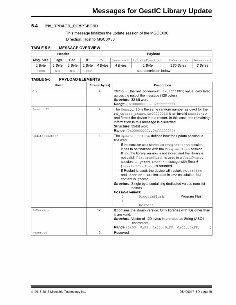
Messages for GestIC Library Update
5.4 FW_UPDATE_COMPLETED
This message finalizes the update session of the MGC3X30.
Direction: Host to MGC3X30
TABLE 5-5: MESSAGE OVERVIEW
Header Payload
Msg. Size Flags Seq. ID Crc SessionID UpdateFunction FwVersion Reserved
1 Byte 1 Byte 1 Byte 1 Byte 4 Bytes 4 Bytes 1 Byte 120 Bytes 3 Bytes
0x88 n.a. n.a. 0x82 see description below
TABLE 5-6: PAYLOAD ELEMENTS
Field Size (in bytes) Description
Crc 4 CRC32 (Ethernet, polynomial: 0x04C11DB7) value, calculated across the rest of the message (128 bytes)Structure: 32-bit wordRange: (0x00000000..0xffffffff)
SessionID 4 The SessionID is the same random number as used for the Fw_Update_Start. 0x00000000 is an invalid SessionID and forces the device into a restart. In this case, the remaining information in this message is discarded.Structure: 32-bit wordRange: (0x00000000..0xffffffff)
UpdateFunction 1 The UpdateFunction defines how the update session is finalized.
- If the session was started as ProgramFlash session, it has to be finalized with the ProgramFlash session. If not, the library version is not stored and the library is not valid. If ProgramFlash is used in a VerifyOnly session, a System_Status message with Error 6 (InvalidFunction) is returned.
- If Restart is used, the device will restart. FwVersion and SessionID are included in Crc calculation, but content is ignored.
Structure: Single byte containing dedicated values (see list below)
Possible values:0 ProgramFlash Program Flash13 Restart
FwVersion 120 It contains the library version. Only libraries with IDs other than 0 are valid. Structure: Vector of 120 bytes interpreted as String (ASCII
characters)Range: (0x00..0xFF, 0x00..0xFF, 0x00..0xFF, . ..)
Reserved 3 Reserved
2013-2015 Microchip Technology Inc. DS40001718D-page 49

MGC3030/3130 GestIC® Library Interface Description
NOTES:
DS40001718D-page 50 2013-2015 Microchip Technology Inc.

MGC3030/3130 GestIC® LIBRARY
INTERFACE DESCRIPTIONAppendix A. I2C™ Command Examples
TABLE A-1: REQUEST_MESSAGE COMMAND EXAMPLES
Requested Function
Request Message
CommentHeader Payload
Msg.Size
Flags Seq. IDMsg.
IDReserved Parameter
— FW version (0x83) 0x0C 0x0 0x0 0x06 0x83 0x00 0x00 0x00 0x00 0x00 0x00 0x00 Fixed command.
Get
Run
time
Par
ame
ters
Trigger (0x1000) 0x0C 0x0 0x0 0x06 0xA2 0x00 0x00 0x00 0x00 0x10 0x00 0x00 Fixed command.
Signal Matching(0x0050, 0x0051, 0x0052, 0x0053, 0x0054)
AFERXATT_S 0x0C 0x0 0x0 0x06 0xA2 0x00 0x00 0x00 0x50 0x00 0x00 0x00
Fixed command.
AFERXATT_W 0x0C 0x0 0x0 0x06 0xA2 0x00 0x00 0x00 0x51 0x00 0x00 0x00
AFERXATT_N 0x0C 0x0 0x0 0x06 0xA2 0x00 0x00 0x00 0x52 0x00 0x00 0x00
AFERXATT_E 0x0C 0x0 0x0 0x06 0xA2 0x00 0x00 0x00 0x53 0x00 0x00 0x00
AFERXATT_C 0x0C 0x0 0x0 0x06 0xA2 0x00 0x00 0x00 0x54 0x00 0x00 0x00
Electrode Mapping(0x0065, 0x0066, 0x0067, 0x0068, 0x0069)
Channelmapping_S 0x0C 0x0 0x0 0x06 0xA2 0x00 0x00 0x00 0x65 0x00 0x00 0x00
Fixed command.
Channelmapping_W 0x0C 0x0 0x0 0x06 0xA2 0x00 0x00 0x00 0x66 0x00 0x00 0x00
Channelmapping_N 0x0C 0x0 0x0 0x06 0xA2 0x00 0x00 0x00 0x67 0x00 0x00 0x00
Channelmapping_E 0x0C 0x0 0x0 0x06 0xA2 0x00 0x00 0x00 0x68 0x00 0x00 0x00
Channelmapping_C 0x0C 0x0 0x0 0x06 0xA2 0x00 0x00 0x00 0x69 0x00 0x00 0x00
Touch Detection (0x0097) and Approach Detection (0x0097)
0x0C 0x0 0x0 0x06 0xA2 0x00 0x00 0x00 0x97 0x00 0x00 0x00 Fixed command.
Approach Detection (0x0081) 0x0C 0x0 0x0 0x06 0xA2 0x00 0x00 0x00 0x81 0x00 0x00 0x00 Fixed command.
AirWheel (0x0090) 0x0C 0x0 0x0 0x06 0xA2 0x00 0x00 0x00 0x90 0x00 0x00 0x00 Fixed command.
Gesture Processing HMM (0x0085) 0x0C 0x0 0x0 0x06 0xA2 0x00 0x00 0x00 0x85 0x00 0x00 0x00 Fixed command.
Calibration Operation Mode (0x0080) 0x0C 0x0 0x0 0x06 0xA2 0x00 0x00 0x00 0x80 0x00 0x00 0x00 Fixed command.
Data Output Enable Mask (0x00A0) 0x0C 0x0 0x0 0x06 0xA2 0x00 0x00 0x00 0xA0 0x00 0x00 0x00 Fixed command.
Data Output Lock Mask (0x00A1) 0x0C 0x0 0x0 0x06 0xA2 0x00 0x00 0x00 0xA1 0x00 0x00 0x00 Fixed command.
Data Output Request Mask (0x00A2) 0x0C 0x0 0x0 0x06 0xA2 0x00 0x00 0x00 0xA2 0x00 0x00 0x00 Fixed command.
Gesture in progress flag control (0x00A3) 0x0C 0x0 0x0 0x06 0xA2 0x00 0x00 0x00 0xA3 0x00 0x00 0x00 Fixed command.
2013-2015 Microchip Technology Inc. DS40001718D-page 51

MG
C303
0/3130 G
estIC® L
ibrary
Interfa
ce De
scriptio
n
DS
40
00
17
18
D-p
ag
e 5
2
20
13
-20
15
Micro
chip
Te
chn
olo
gy In
c.
Comment
Argument1
0 0x00 0x00 0x00 Fixed command.
0 0x00 0x00 0x00 Fixed command.
0 0x00 0x00 0x00 Fixed command.
0 0x00 0x00 0x00 Fixed command.
0 0x00 0x00 0x00 Fixed command.
0 0x00 0x00 0x00 Fixed command.
0 0x00 0x00 0x00
Argument0 (8-bit) defines the signal matching value for each electrode. These values are just examples.
0 0x00 0x00 0x00
0 0x00 0x00 0x00
0 0x00 0x00 0x00
0 0x00 0x00 0x00
0 0x00 0x00 0x00Argument0 (8-bit) defines the respective Rx Channel for each electrode. This value can be ‘0’ for Rx0, ‘1’ for Rx1, ‘2’ for Rx2, ‘3’ for Rx3 or ‘4’ for Rx4. These values are just examples.
0 0x00 0x00 0x00
0 0x00 0x00 0x00
0 0x00 0x00 0x00
0 0x00 0x00 0x00
TABLE A-2: SET_RUNTIME_PARAMETER COMMAND EXAMPLES
Requested Function
Set_Runtime_Parameter
Header Payload
Msg. Size
Flags Seq. IDRuntime
Parameter ID
Reserved Argument0
Com
mo
n C
ate
gor
y
Trigger(0x1000)
Force Calibration 0x10 0x0 0x0 0xA2 0x00 0x10 0x00 0x00 0x00 0x00 0x00 0x00 0x0
Enter Deep Sleep 1 0x10 0x0 0x0 0xA2 0x00 0x10 0x00 0x00 0x02 0x00 0x00 0x00 0x0
Enter Deep Sleep 2 0x10 0x0 0x0 0xA2 0x00 0x10 0x00 0x00 0x03 0x00 0x00 0x00 0x0
MakePersistent(0xFF00)
Store RTPs for AFE 0x10 0x0 0x0 0xA2 0x00 0xFF 0x00 0x00 0x00 0x00 0x00 0x00 0x0
Store RTPs for DSP 0x10 0x0 0x0 0xA2 0x00 0xFF 0x00 0x00 0x01 0x00 0x00 0x00 0x0
Store RTPs for System 0x10 0x0 0x0 0xA2 0x00 0xFF 0x00 0x00 0x02 0x00 0x00 0x00 0x0
Ana
log
Fro
nt-E
nd C
ate
gory Signal Matching
(0x0050, 0x0051, 0x0052, 0x0053, 0x0054)
AFERXATT_S 0x10 0x0 0x0 0xA2 0x50 0x00 0x00 0x00 0x98 0x00 0x00 0x00 0x0
AFERXATT_W 0x10 0x0 0x0 0xA2 0x51 0x00 0x00 0x00 0x96 0x00 0x00 0x00 0x0
AFERXATT_N 0x10 0x0 0x0 0xA2 0x52 0x00 0x00 0x00 0x98 0x00 0x00 0x00 0x0
AFERXATT_E 0x10 0x0 0x0 0xA2 0x53 0x00 0x00 0x00 0x91 0x00 0x00 0x00 0x0
AFERXATT_C 0x10 0x0 0x0 0xA2 0x54 0x00 0x00 0x00 0xD9 0x00 0x00 0x00 0x0
Electrode Mapping(0x0065, 0x0066, 0x0067, 0x0068, 0x0069)
Channelmapping_S 0x10 0x0 0x0 0xA2 0x65 0x00 0x00 0x00 0x03 0x00 0x00 0x00 0x0
Channelmapping_W 0x10 0x0 0x0 0xA2 0x66 0x00 0x00 0x00 0x01 0x00 0x00 0x00 0x0
Channelmapping_N 0x10 0x0 0x0 0xA2 0x67 0x00 0x00 0x00 0x02 0x00 0x00 0x00 0x0
Channelmapping_E 0x10 0x0 0x0 0xA2 0x68 0x00 0x00 0x00 0x04 0x00 0x00 0x00 0x0
Channelmapping_C 0x10 0x0 0x0 0xA2 0x69 0x00 0x00 0x00 0x00 0x00 0x00 0x00 0x0
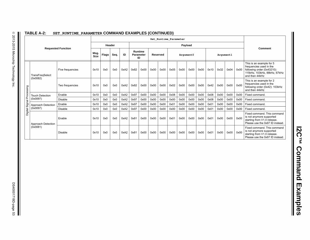
I2C
™ C
om
man
d E
xam
ple
s
2
01
3-2
01
5 M
icroch
ip T
ech
no
log
y Inc.
DS
40
00
17
18
D-p
ag
e 5
3
Dig
ital S
igna
l Pro
cess
ing
x32 0x04 0x00
This is an example for 5 frequencies used in the following order (0x43210): 115kHz, 103kHz, 88kHz, 67kHz and then 44kHz
x00 0x00 0x00
This is an example for 2 frequencies used in the following order (0x42): 103kHz and then 44kHz
x00 0x00 0x00 Fixed command.
x00 0x00 0x00 Fixed command.
x00 0x00 0x00 Fixed command.
x00 0x00 0x00 Fixed command.
x00 0x00 0x00
Fixed command. This command is not anymore supported starting from V1.0 release. Please use the 0x97 ID instead.
x00 0x00 0x00
Fixed command. This command is not anymore supported starting from V1.0 release. Please use the 0x97 ID instead.
TA
Comment
rgument1
TransFreqSelect(0x0082)
Five frequencies 0x10 0x0 0x0 0xA2 0x82 0x00 0x00 0x00 0x05 0x00 0x00 0x00 0x10 0
Two frequencies 0x10 0x0 0x0 0xA2 0x82 0x00 0x00 0x00 0x02 0x00 0x00 0x00 0x42 0
Touch Detection(0x0097)
Enable 0x10 0x0 0x0 0xA2 0x97 0x00 0x00 0x00 0x08 0x00 0x00 0x00 0x08 0
Disable 0x10 0x0 0x0 0xA2 0x97 0x00 0x00 0x00 0x00 0x00 0x00 0x00 0x08 0
Approach Detection(0x0097)
Enable 0x10 0x0 0x0 0xA2 0x97 0x00 0x00 0x00 0x01 0x00 0x00 0x00 0x01 0
Disable 0x10 0x0 0x0 0xA2 0x97 0x00 0x00 0x00 0x00 0x00 0x00 0x00 0x01 0
Approach Detection(0x0081)
Enable 0x10 0x0 0x0 0xA2 0x81 0x00 0x00 0x00 0x01 0x00 0x00 0x00 0x01 0
Disable 0x10 0x0 0x0 0xA2 0x81 0x00 0x00 0x00 0x00 0x00 0x00 0x00 0x01 0
BLE A-2: SET_RUNTIME_PARAMETER COMMAND EXAMPLES (CONTINUED)
Requested Function
Set_Runtime_Parameter
Header Payload
Msg. Size
Flags Seq. IDRuntime
Parameter ID
Reserved Argument0 A

MG
C303
0/3130 G
estIC® L
ibrary
Interfa
ce De
scriptio
n
DS
40
00
17
18
D-p
ag
e 5
4
20
13
-20
15
Micro
chip
Te
chn
olo
gy In
c.
0 0x00 0x00 0x00 Fixed command.
0 0x00 0x00 0x00 Fixed command.
F 0x00 0x00 0x00 The Argument 0 (8-bit) defines which Gestures need to be configured. The Argument 1 defines the mask for the Gestures which need to be configured.These values are just examples.
F 0x00 0x00 0x00
0 0x00 0x00 0x00
F 0x00 0x00 0x00 Fixed command.
F 0x00 0x00 0x00 Fixed command.
F 0x18 0x00 0x00The Argument 0 defines which Data need to be enabled or disabled. The Argument 1 defines the mask for the Data which need to be configured.These values are just examples.
F 0x18 0x00 0x00
0 0x00 0x00 0x00
0 0x08 0x00 0x00
F 0x18 0x00 0x00The Argument 0 defines which Data need to be locked or unlocked. The Argument 1 defines the mask for the Data which need to be configured.These values are just examples.
F 0x18 0x00 0x00
0 0x00 0x00 0x00
0 0x08 0x00 0x00
F 0x18 0x00 0x00 The Argument 0 defines which Data need to be requested. This is only valid for the next message.The Argument 1 defines the mask for the Data which need to be configured.These values are just examples.
F 0x18 0x00 0x00
0 0x00 0x00 0x00
1 0x00 0x00 0x00 Fixed command.
1 0x00 0x00 0x00 Fixed command.
Comment
Argument1
Sys
tem
Cat
ego
ry
AirWheel(0x0090)
Enable 0x10 0x0 0x0 0xA2 0x90 0x00 0x00 0x00 0x20 0x00 0x00 0x00 0x2
Disable 0x10 0x0 0x0 0xA2 0x90 0x00 0x00 0x00 0x00 0x00 0x00 0x00 0x2
Gesture Processing HMM(0x0085)
Enable All Gestures 0x10 0x0 0x0 0xA2 0x85 0x00 0x00 0x00 0x7F 0x00 0x00 0x00 0x7
Enable Only Flick Gestures
0x10 0x0 0x0 0xA2 0x85 0x00 0x00 0x00 0x1F 0x00 0x00 0x00 0x7
Enable in Addition Circles 0x10 0x0 0x0 0xA2 0x85 0x00 0x00 0x00 0x60 0x00 0x00 0x00 0x6
Calibration Operation Mode(0x0080)
Enable 0x10 0x0 0x0 0xA2 0x80 0x00 0x00 0x00 0x00 0x00 0x00 0x00 0x3
Disable 0x10 0x0 0x0 0xA2 0x80 0x00 0x00 0x00 0x3F 0x00 0x00 0x00 0x3
Data Output Enable Mask(0x00A0)
Enable All Data 0x10 0x0 0x0 0xA2 0xA0 0x00 0x00 0x00 0x3F 0x18 0x00 0x00 0x3
Enable DSP, Gestures and Noise Power
0x10 0x0 0x0 0xA2 0xA0 0x00 0x00 0x00 0x23 0x00 0x00 0x00 0x3
Enable Only Data: Noise (others not changed)
0x10 0x0 0x0 0xA2 0xA0 0x00 0x00 0x00 0x10 0x00 0x00 0x00 0x1
Disable Only Data: CIC (others not changed)
0x10 0x0 0x0 0xA2 0xA0 0x00 0x00 0x00 0x00 0x00 0x00 0x00 0x0
Data Output Lock Mask(0x00A1)
Lock All Data 0x10 0x0 0x0 0xA2 0xA1 0x00 0x00 0x00 0x3F 0x18 0x00 0x00 0x3
Lock DSP, Gestures and Noise Power
0x10 0x0 0x0 0xA2 0xA1 0x00 0x00 0x00 0x23 0x00 0x00 0x00 0x3
Lock Only Data: Noise (others not changed)
0x10 0x0 0x0 0xA2 0xA1 0x00 0x00 0x00 0x10 0x00 0x00 0x00 0x1
UnLock Only Data: CIC (others not changed)
0x10 0x0 0x0 0xA2 0xA1 0x00 0x00 0x00 0x00 0x00 0x00 0x00 0x0
Data Output Request Mask(0x00A2)
Request All Data 0x10 0x0 0x0 0xA2 0xA2 0x00 0x00 0x00 0x3F 0x18 0x00 0x00 0x3
Request DSP, Gestures and Noise Power
0x10 0x0 0x0 0xA2 0xA2 0x00 0x00 0x00 0x23 0x00 0x00 0x00 0x3
Request Only Data: Noise 0x10 0x0 0x0 0xA2 0xA2 0x00 0x00 0x00 0x10 0x00 0x00 0x00 0x1
Gesture in Progress Flag Control(0x00A3)
Enable 0x10 0x0 0x0 0xA2 0xA3 0x00 0x00 0x00 0x01 0x00 0x00 0x00 0x0
Disable 0x10 0x0 0x0 0xA2 0xA3 0x00 0x00 0x00 0x00 0x00 0x00 0x00 0x0
TABLE A-2: SET_RUNTIME_PARAMETER COMMAND EXAMPLES (CONTINUED)
Requested Function
Set_Runtime_Parameter
Header Payload
Msg. Size
Flags Seq. IDRuntime
Parameter ID
Reserved Argument0

I2C
™ C
om
man
d E
xam
ple
s
2
01
3-2
01
5 M
icroch
ip T
ech
no
log
y Inc.
DS
40
00
17
18
D-p
ag
e 5
5
TA
Comment
Parameter
Da(coco10
0x73 — — Negative Calibration.
0x73 — — Calibration finished.
0x73 — — Idle Calibration.
0x73 — — Calibration finished.
Da(coco10
0x10 0x00 0x00 0x03: Flick East to West0x10: Flick Gesture0x00 0x00 0x00
0x10 0x04 0x00 0x05: Flick North to South0x10: Flick Gesture0x00 0x00 0x00
0x10 0x04 0x00 0x03: Flick South to North0x10: Flick Gesture0x00 0x00 0x00
0x10 0x00 0x00 0x03: Flick West to East0x10: Flick Gesture0x00 0x00 0x00
BLE A-3: SENSOR_DATA_OUTPUT COMMAND EXAMPLES
Requested Function User Action
Sensor_Data_Output
Header Payload
Msg. Size
Flags Seq. IDData Output Config. Mask
Time Stamp
System Info
ta Output contains only DSPStatus field nfigured using the Set_Runtime_Parameter
mmand: 00 00 A2 A0 00 00 00 01 00 00 00 FF FF FF FF)
No action
0x0A 0x08 0x26 0x91 0x01 0x01 0x5D 0x80 0x10
0x0A 0x08 0x27 0x91 0x01 0x01 0x5E 0x80 0x00
0x0A 0x08 0x28 0x91 0x01 0x01 0x5D 0x80 0x20
0x0A 0x08 0x29 0x91 0x01 0x01 0x5E 0x80 0x00
ta Output contains only Gesture Data field nfigured using the Set_Runtime_Parameter
mmand: 00 00 A2 A0 00 00 00 02 00 00 00 FF FF FF FF)
Flick East to west0x0C 0x08 0x31 0x91 0x02 0x01 0x82 0x80 0x03
0x0C 0x08 0x32 0x91 0x02 0x01 0x83 0x80 0x00
Flick North to South0x0C 0x08 0x33 0x91 0x02 0x01 0x13 0x80 0x05
0x0C 0x08 0x34 0x91 0x02 0x01 0x14 0x80 0x00
Flick South to North0x0C 0x08 0x35 0x91 0x02 0x01 0x53 0x80 0x04
0x0C 0x08 0x36 0x91 0x02 0x01 0x54 0x80 0x00
Flick West to East0x0C 0x08 0x37 0x91 0x02 0x01 0x5D 0x80 0x02
0x0C 0x08 0x38 0x91 0x02 0x01 0x5E 0x80 0x00

MG
C303
0/3130 G
estIC® L
ibrary
Interfa
ce De
scriptio
n
DS
40
00
17
18
D-p
ag
e 5
6
20
13
-20
15
Micro
chip
Te
chn
olo
gy In
c.
0x00 0x00 0x00 0x80 Gesture Recognizer started
0x03 0x10 0x00 0x00 Gesture recognized (Flick East to West)0x00 0x00 0x00 0x00
0x00 0x00 0x00 0x80 Gesture Recognizer started
0x01 0x00 0x00 0x00Garbage recognized
0x00 0x00 0x00 0x00
0x00 0x00 0x00 0x80 Gesture Recognizer started
0x03 0x10 0x04 0x00 Gesture recognized (Flick East to West)0x00 0x00 0x00 0x00
0x00 0x00 0x00 0x80 Gesture Recognizer started
0x05 0x10 0x04 0x00 Gesture recognized (Flick North to South)0x00 0x00 0x00 0x00
0x00 0x00 0x00 0x80 Gesture Recognizer started
0x04 0x10 0x04 0x00 Gesture recognized (Flick South to North)0x00 0x00 0x00 0x00
0x00 0x00 0x00 0x80 Gesture Recognizer started
0x02 0x10 0x02 0x00 Gesture recognized (Flick West to East)0x00 0x00 0x00 0x00
0x00 0x00 0x00 0x80 Gesture Recognizer started
0x00 0x00 0x00 0x00Circle Gesture not recognized because AirWheel is On
0x00 0x00 0x00 0x80 Gesture Recognizer started
0x00 0x00 0x00 0x00Circle gesture not recognized because AirWheel is On
Comment
Parameter
Data Output contains only Gesture Data field (configured using the Set_Runtime_Parameter command: 10 00 00 A2 A0 00 00 00 02 00 00 00 FF FF FF FF)
Gesture in Progress is activated using the Set_Runtime_Parameter command: 10 00 00 A2 A3 00 00 00 01 00 00 00 FF FF FF FF)
Flick East to West
0x0C 0x08 0x3A 0x91 0x02 0x01 0x19 0x81
0x0C 0x08 0x3B 0x91 0x02 0x01 0x45 0x81
0x0C 0x08 0x3C 0x91 0x02 0x01 0x46 0x81
Just move hand
0x0C 0x08 0x3D 0x91 0x02 0x01 0x47 0x81
0x0C 0x08 0x3E 0x91 0x02 0x01 0x6E 0x81
0x0C 0x08 0x3F 0x91 0x02 0x01 0x6F 0x81
Flick East to West
0x0C 0x08 0x40 0x91 0x02 0x01 0x83 0x81
0x0C 0x08 0x41 0x91 0x02 0x01 0xAC 0x80
0x0C 0x08 0x42 0x91 0x02 0x01 0xAD 0x80
Flick North to South
0x0C 0x08 0x43 0x91 0x02 0x01 0x67 0x81
0x0C 0x08 0x44 0x91 0x02 0x01 0x8A 0x80
0x0C 0x08 0x45 0x91 0x02 0x01 0x8B 0x80
Flick South to North
0x0C 0x08 0x46 0x91 0x02 0x01 0x67 0x81
0x0C 0x08 0x47 0x91 0x02 0x01 0x8E 0x80
0x0C 0x08 0x48 0x91 0x02 0x01 0x8F 0x80
Flick West to East
0x0C 0x08 0x49 0x91 0x02 0x01 0x6E 0x81
0x0C 0x08 0x4A 0x91 0x02 0x01 0x9A 0x80
0x0C 0x08 0x4B 0x91 0x02 0x01 0x9B 0x80
Clockwise Circle
0x0C 0x08 0x4C 0x91 0x02 0x01 0x81 0x80
0x0C 0x08 0x4D 0x91 0x02 0x01 0xD6 0x80
Counter Clockwise Circle
0x0C 0x08 0x4E 0x91 0x02 0x01 0x05 0x80
0x0C 0x08 0x4F 0x91 0x02 0x01 0x56 0x80
TABLE A-3: SENSOR_DATA_OUTPUT COMMAND EXAMPLES (CONTINUED)
Requested Function User Action
Sensor_Data_Output
Header Payload
Msg. Size
Flags Seq. IDData Output Config. Mask
Time Stamp
System Info

I2C
™ C
om
man
d E
xam
ple
s
2
01
3-2
01
5 M
icroch
ip T
ech
no
log
y Inc.
DS
40
00
17
18
D-p
ag
e 5
7
Da(coco10
0x00 0x09 0x00Center Touch detected and the touch counter = 0x09
0x00 0x00 0x00 Touch Counter Reset
0x02 0x00 0x00 Tap on Center electrode detected0x00 0x00 0x00
TA
Comment
Parameter
ta Output contains only Touch Data field nfigured using the Set_Runtime_Parameter
mmand: 00 00 A2 A0 00 00 00 04 00 00 00 FF FF FF FF)
Touch Center Electrode
0x0C 0x08 0x45 0x91 0x04 0x01 0x51 0x81 0x10
0x0C 0x08 0x46 0x91 0x04 0x01 0x52 0x81 0x10
0x0C 0x08 0x47 0x91 0x04 0x01 0x5D 0x81 0x00
0x0C 0x08 0x48 0x91 0x04 0x01 0x5E 0x81 0x00
BLE A-3: SENSOR_DATA_OUTPUT COMMAND EXAMPLES (CONTINUED)
Requested Function User Action
Sensor_Data_Output
Header Payload
Msg. Size
Flags Seq. IDData Output Config. Mask
Time Stamp
System Info

MGC3030/3130 GestIC® Library Interface Description
NOTES:
DS40001718D-page 58 2013-2015 Microchip Technology Inc.

MGC3030/3130 GestIC® LIBRARY
INTERFACE DESCRIPTIONAppendix B. Glossary
TABLE B-1: GLOSSARYTerm Definition
AFE Analog front end
Application Host PC or embedded controller which controls the MGC3X30
Aurea MGC3X30 PC control software with graphical user interface
Colibri Suite Embedded DSP suite within the GestIC® Library
Deep Sleep MGC3X30 Power-Saving mode
E-field Electrical field
Frame Electrodes Rectangular set of four electrodes for E-field sensing
GestIC® Technology Microchip’s patented technology providing 3D free-space gesture recognition utilizing the principles of electrical near-field sensing
GestIC® Library Includes the implementation of MGC3X30 features and is delivered as a binary file preprogrammed on the MGC3X30
Gesture Recognition Microchip’s stochastic HMM classifier to automatically detect and classify hand movement patterns
Gesture Set A set of provided hand movement patterns
Hand Brick Copper coated test block (40x40x70 mm)
Hillstar MGC3130 Development Kit
HMM Hidden Markov Model
MGC3130 Single-Zone 3D Gesture Sensing Controller
Position Tracking GestIC® technology feature
Sabrewing MGC3X30 evaluation board
Self Wake-up MGC3X30 Power-Saving mode
Sensing Area Area enclosed by the four frame electrodes
Sensing Space Space above sensing area
Signal Deviation Term for the delta of the sensor signal on approach of the hand versus non-approach
Spacer Brick Spacer between the sensor layer and hand brick(Styrofoam block 40x40xh mm) with h= 1/2/3/5/8/12 cm
SPU Signal Processing Unit
Approach Detection GestIC® technology feature: Power-Saving mode of the MGC3X30 with approach detection
Woodstar – MGC3030 Development Kit
MGC3030 – 3D Gesture Controller
2013-2015 Microchip Technology Inc. DS40001718D-page 59

MGC3030/3130 GestIC® Library Interface Description
NOTES:
DS40001718D-page 60 2013-2015 Microchip Technology Inc.

2013-2015 Microchip Technology Inc. DS40001718D-page 61
AMERICASCorporate Office2355 West Chandler Blvd.Chandler, AZ 85224-6199Tel: 480-792-7200 Fax: 480-792-7277Technical Support: http://www.microchip.com/supportWeb Address: www.microchip.com
AtlantaDuluth, GA Tel: 678-957-9614 Fax: 678-957-1455
Austin, TXTel: 512-257-3370
BostonWestborough, MA Tel: 774-760-0087 Fax: 774-760-0088
ChicagoItasca, IL Tel: 630-285-0071 Fax: 630-285-0075
ClevelandIndependence, OH Tel: 216-447-0464 Fax: 216-447-0643
DallasAddison, TX Tel: 972-818-7423 Fax: 972-818-2924
DetroitNovi, MI Tel: 248-848-4000
Houston, TX Tel: 281-894-5983
IndianapolisNoblesville, IN Tel: 317-773-8323Fax: 317-773-5453
Los AngelesMission Viejo, CA Tel: 949-462-9523 Fax: 949-462-9608
New York, NY Tel: 631-435-6000
San Jose, CA Tel: 408-735-9110
Canada - TorontoTel: 905-673-0699 Fax: 905-673-6509
ASIA/PACIFICAsia Pacific OfficeSuites 3707-14, 37th FloorTower 6, The GatewayHarbour City, KowloonHong KongTel: 852-2943-5100Fax: 852-2401-3431
Australia - SydneyTel: 61-2-9868-6733Fax: 61-2-9868-6755
China - BeijingTel: 86-10-8569-7000 Fax: 86-10-8528-2104
China - ChengduTel: 86-28-8665-5511Fax: 86-28-8665-7889
China - ChongqingTel: 86-23-8980-9588Fax: 86-23-8980-9500
China - HangzhouTel: 86-571-8792-8115 Fax: 86-571-8792-8116
China - Hong Kong SARTel: 852-2943-5100 Fax: 852-2401-3431
China - NanjingTel: 86-25-8473-2460Fax: 86-25-8473-2470
China - QingdaoTel: 86-532-8502-7355Fax: 86-532-8502-7205
China - ShanghaiTel: 86-21-5407-5533 Fax: 86-21-5407-5066
China - ShenyangTel: 86-24-2334-2829Fax: 86-24-2334-2393
China - ShenzhenTel: 86-755-8864-2200 Fax: 86-755-8203-1760
China - WuhanTel: 86-27-5980-5300Fax: 86-27-5980-5118
China - XianTel: 86-29-8833-7252Fax: 86-29-8833-7256
China - XiamenTel: 86-592-2388138 Fax: 86-592-2388130
China - ZhuhaiTel: 86-756-3210040 Fax: 86-756-3210049
ASIA/PACIFICIndia - BangaloreTel: 91-80-3090-4444 Fax: 91-80-3090-4123
India - New DelhiTel: 91-11-4160-8631Fax: 91-11-4160-8632
India - PuneTel: 91-20-3019-1500
Japan - OsakaTel: 81-6-6152-7160 Fax: 81-6-6152-9310
Japan - TokyoTel: 81-3-6880- 3770 Fax: 81-3-6880-3771
Korea - DaeguTel: 82-53-744-4301Fax: 82-53-744-4302
Korea - SeoulTel: 82-2-554-7200Fax: 82-2-558-5932 or 82-2-558-5934
Malaysia - Kuala LumpurTel: 60-3-6201-9857Fax: 60-3-6201-9859
Malaysia - PenangTel: 60-4-227-8870Fax: 60-4-227-4068
Philippines - ManilaTel: 63-2-634-9065Fax: 63-2-634-9069
SingaporeTel: 65-6334-8870Fax: 65-6334-8850
Taiwan - Hsin ChuTel: 886-3-5778-366Fax: 886-3-5770-955
Taiwan - KaohsiungTel: 886-7-213-7830
Taiwan - TaipeiTel: 886-2-2508-8600 Fax: 886-2-2508-0102
Thailand - BangkokTel: 66-2-694-1351Fax: 66-2-694-1350
EUROPEAustria - WelsTel: 43-7242-2244-39Fax: 43-7242-2244-393Denmark - CopenhagenTel: 45-4450-2828 Fax: 45-4485-2829
France - ParisTel: 33-1-69-53-63-20 Fax: 33-1-69-30-90-79
Germany - DusseldorfTel: 49-2129-3766400
Germany - MunichTel: 49-89-627-144-0 Fax: 49-89-627-144-44
Germany - PforzheimTel: 49-7231-424750
Italy - Milan Tel: 39-0331-742611 Fax: 39-0331-466781
Italy - VeniceTel: 39-049-7625286
Netherlands - DrunenTel: 31-416-690399 Fax: 31-416-690340
Poland - WarsawTel: 48-22-3325737
Spain - MadridTel: 34-91-708-08-90Fax: 34-91-708-08-91
Sweden - StockholmTel: 46-8-5090-4654
UK - WokinghamTel: 44-118-921-5800Fax: 44-118-921-5820
Worldwide Sales and Service
03/25/14
Top Related