


Languages
Pages
Legal


Lecture 3, Slide 1EE40 Fall 2004 Prof. White
Announcements
• HW #1 due Thursday, Sept. 9, in EE40 homework box in 240 Cory
http://www-inst.eecs.berkeley.edu/~ee40
Lecture 3, Slide 2EE40 Fall 2004 Prof. White
Lecture #3
OUTLINE
• Circuit element I-V characteristics
• Construction of a circuit model
• Kirchhoff’s laws – a closer look
Reading
(Chapter 1, begin Ch. 2)

Lecture 3, Slide 3EE40 Fall 2004 Prof. White
Current vs. Voltage (I-V) Characteristic
• Voltage sources, current sources, and resistors can be described by plotting the current (i) as a function of the voltage (v)
• Later, we will see that the I-V characteristic of any circuit consisting only of sources and resistors is a straight line.
+v_
i
Lecture 3, Slide 4EE40 Fall 2004 Prof. White
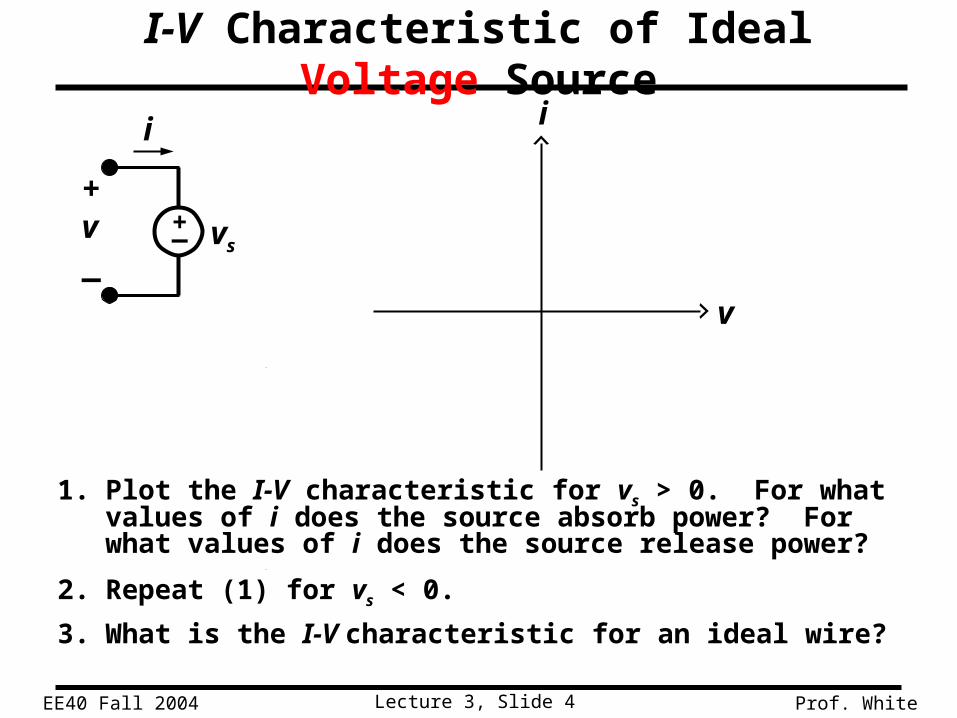
I-V Characteristic of Ideal Voltage Source
1. Plot the I-V characteristic for vs > 0. For what values of i does the source absorb power? For what values of i does the source release power?
2. Repeat (1) for vs < 0.
3. What is the I-V characteristic for an ideal wire?
+_ vs
i i
+v_
v

Lecture 3, Slide 5EE40 Fall 2004 Prof. White
I-V Characteristic of Ideal Current Source
1. Plot the I-V characteristic for is > 0. For what values of v does the source absorb power? For what values of v does the source release power?
2. Repeat (1) for is < 0.
3. What is the I-V characteristic for an open circuit?
i i
+v_
v
is
Lecture 3, Slide 6EE40 Fall 2004 Prof. White
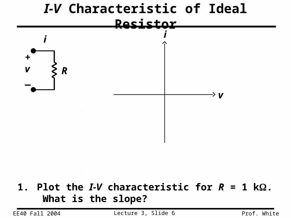
I-V Characteristic of Ideal Resistor
1. Plot the I-V characteristic for R = 1 k. What is the slope?
i i
+v_
v
R
Lecture 3, Slide 7EE40 Fall 2004 Prof. White
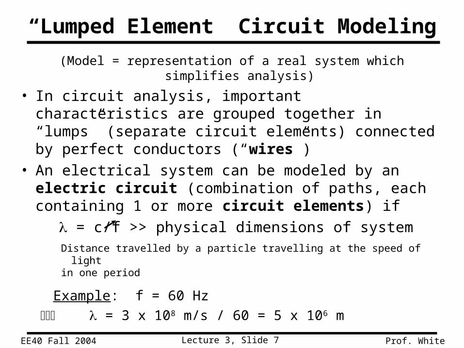
“Lumped Element” Circuit Modeling
(Model = representation of a real system which simplifies analysis)
• In circuit analysis, important characteristics are grouped together in “lumps” (separate circuit elements) connected by perfect conductors (“wires”)
• An electrical system can be modeled by an electric circuit (combination of paths, each containing 1 or more circuit elements) if
= c/f >> physical dimensions of systemDistance travelled by a particle travelling at the speed of lightin one period
Example: f = 60 Hz
= 3 x 10⁸ m/s / 60 = 5 x 10⁶ m
Lecture 3, Slide 8EE40 Fall 2004 Prof. White
Construction of a Circuit Model
• The electrical behavior of each physical component is of primary interest.
• We need to account for undesired as well as desired electrical effects.
• Simplifying assumptions should be made wherever reasonable.
Lecture 3, Slide 9EE40 Fall 2004 Prof. White
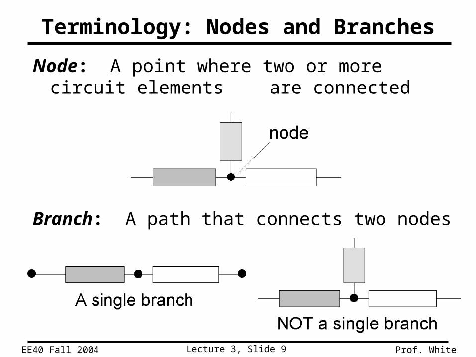
Terminology: Nodes and Branches
Node: A point where two or more circuit elements are connected
Branch: A path that connects two nodes
Lecture 3, Slide 10EE40 Fall 2004 Prof. White
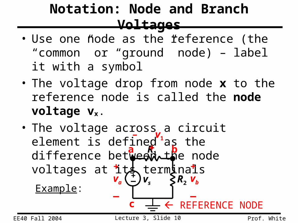
Notation: Node and Branch Voltages
• Use one node as the reference (the “common” or “ground” node) – label it with a symbol
• The voltage drop from node x to the reference node is called the node voltage vx.
• The voltage across a circuit element is defined as the difference between the node voltages at its terminals
Example:
+_ vs
+va
_
+vb
_
a b
c
R1
R2
– v1 +
REFERENCE NODE

Lecture 3, Slide 11EE40 Fall 2004 Prof. White
• Use reference directions to determine whether currents are “entering” or “leaving” the node – with no concern about actual current directions
Using Kirchhoff’s Current Law (KCL)
i1
i4
i3
i2
Consider a node connecting several branches:

Lecture 3, Slide 12EE40 Fall 2004 Prof. White
Formulations of Kirchhoff’s Current Law
Formulation 1:
Sum of currents entering node = sum of currents leaving node
Formulation 2:
Algebraic sum of currents entering node = 0• Currents leaving are included with a minus sign.
Formulation 3:
Algebraic sum of currents leaving node = 0• Currents entering are included with a minus sign.
(Charge stored in node is zero.)
Lecture 3, Slide 13EE40 Fall 2004 Prof. White
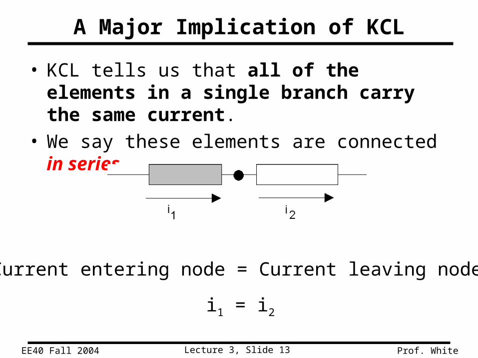
A Major Implication of KCL
• KCL tells us that all of the elements in a single branch carry the same current.
• We say these elements are connected in series.
Current entering node = Current leaving node
i1 = i2

Lecture 3, Slide 14EE40 Fall 2004 Prof. White
KCL Example
5 mA
15 mA
i-10 mA
3 formulations of KCL:
1.
2.
3.
Currents entering the node:
Currents leaving the node:
Lecture 3, Slide 15EE40 Fall 2004 Prof. White
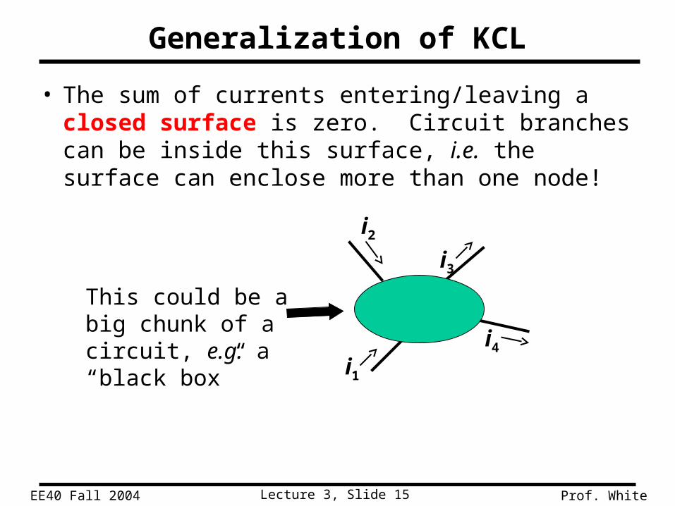
Generalization of KCL
• The sum of currents entering/leaving a closed surface is zero. Circuit branches can be inside this surface, i.e. the surface can enclose more than one node!
This could be a big chunk of a circuit, e.g. a “black box” i1
i2
i3
i4

Lecture 3, Slide 16EE40 Fall 2004 Prof. White
Generalized KCL Examples
5A
2A i
50 mA
i

Lecture 3, Slide 17EE40 Fall 2004 Prof. White
• Use reference polarities to determine whether a voltage is dropped – with no concern about actual voltage polarities
Using Kirchhoff’s Voltage Law (KVL)
Consider a branch which forms part of a loop:
+v1
_loop voltage
“drop”
–v2
+
loop voltage “rise”
(negative drop)
Lecture 3, Slide 18EE40 Fall 2004 Prof. White
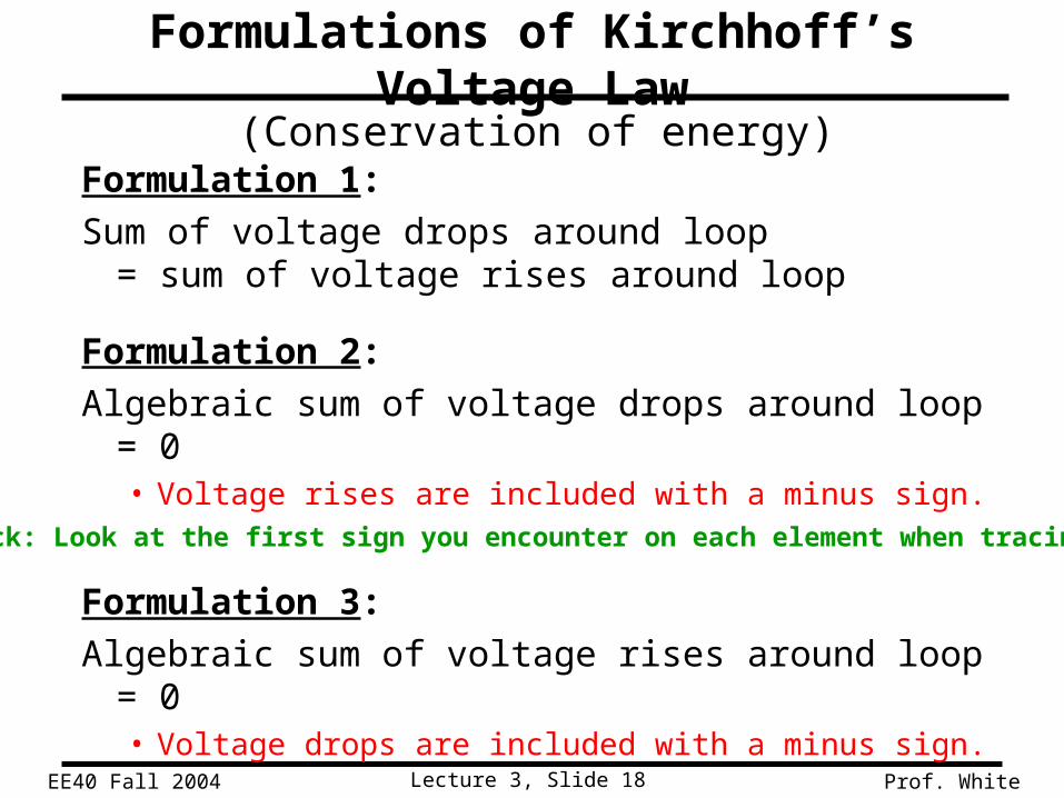
Formulations of Kirchhoff’s Voltage Law
Formulation 1:
Sum of voltage drops around loop = sum of voltage rises around loop
Formulation 2:
Algebraic sum of voltage drops around loop = 0• Voltage rises are included with a minus sign.
Formulation 3:
Algebraic sum of voltage rises around loop = 0• Voltage drops are included with a minus sign.
(Conservation of energy)
(Handy trick: Look at the first sign you encounter on each element when tracing the loop.)

Lecture 3, Slide 19EE40 Fall 2004 Prof. White
A Major Implication of KVL
• KVL tells us that any set of elements which are connected at both ends carry the same voltage.
• We say these elements are connected in parallel.
Applying KVL in the clockwise direction, starting at the top:
vb – va = 0 vb = va
+va
_
+ vb
_

Lecture 3, Slide 20EE40 Fall 2004 Prof. White
Path 1:
Path 2:
Path 3:
vcva
+
+
3
21
+
vb
v3v2
+
+
-
Three closed paths:
a b c
KVL Example

Lecture 3, Slide 21EE40 Fall 2004 Prof. White
• No time-varying magnetic flux through the loopOtherwise, there would be an induced voltage (Faraday’s Law)
Avoid these loops!
How do we deal with antennas (EECS 117A)?
Include a voltage source as the circuit representation of the induced voltage or “noise”.(Use a lumped model rather than a distributed (wave) model.)
• Note: Antennas are designed to “pick up” electromagnetic waves; “regular circuits” often do so undesirably.
)t(B
)t(v+
An Underlying Assumption of KVL

Lecture 3, Slide 22EE40 Fall 2004 Prof. White
Consider a circuit with multiple resistors connected in series.Find their “equivalent resistance”.
• KCL tells us that the same current (I) flows through every resistor
• KVL tells us
Equivalent resistance of resistors in series is the sum
R2
R1
VSS
I
R3
R4
+
Resistors in Series

Lecture 3, Slide 23EE40 Fall 2004 Prof. White
I = VSS / (R1 + R2 + R3 + R4)
Voltage Divider
+– V1
+– V3
R2
R1
VSS
I
R3
R4
+

Lecture 3, Slide 24EE40 Fall 2004 Prof. White
SS4321
22
VRRRR
RV
Correct, if nothing elseis connected to nodes
because R5 removes conditionof resistors in series
SS4321
22
VRRRR
RV
≠
When can the Voltage Divider Formula be Used?
+– V2
R2
R1
VSS
I
R3
R4
+
R2
R1
VSS
I
R3
R4
+
R5
+– V2

Lecture 3, Slide 25EE40 Fall 2004 Prof. White
• KVL tells us that the same voltage is dropped across each resistor
Vx = I1 R1 = I2 R2
• KCL tells us
R2R1 ISS
I2I1
x
Resistors in Parallel
Consider a circuit with two resistors connected in parallel.Find their “equivalent resistance”.

Lecture 3, Slide 26EE40 Fall 2004 Prof. White
What single resistance Req is equivalent to three resistors in parallel?
+
V
I
V
+
I
R3R2R1 Req
eq
General Formula for Parallel Resistors
Equivalent conductance of resistors in parallel is the sum

Lecture 3, Slide 27EE40 Fall 2004 Prof. White
Vx = I1 R1 = ISS Req
Current Divider
R2R1 ISS
I2I1
x
Lecture 3, Slide 28EE40 Fall 2004 Prof. White
R2R1 I
I2I1 I3R3
+
V
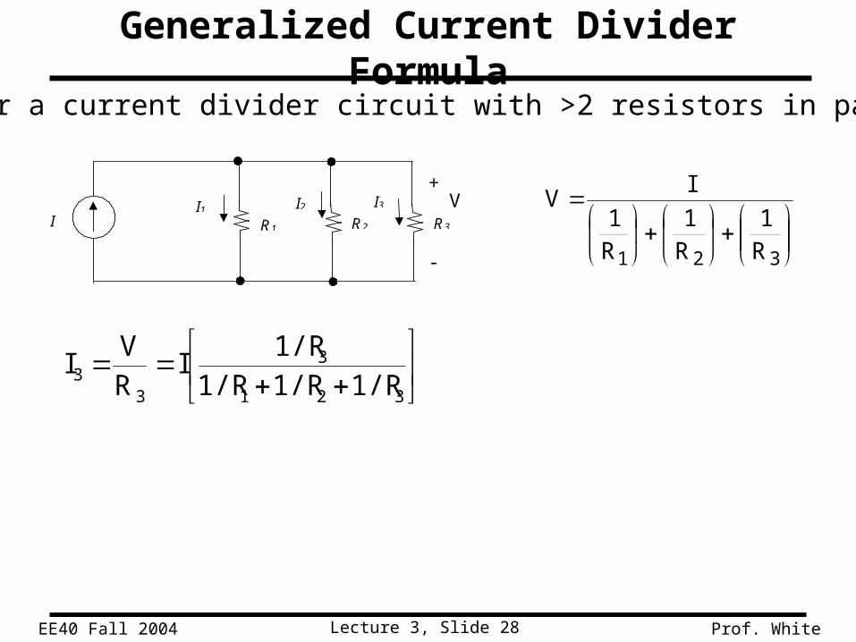
321 R1
R1
R1
IV
321
3
33 1/R1/R1/R
1/RI
RV
I
Generalized Current Divider Formula
Consider a current divider circuit with >2 resistors in parallel:

Lecture 3, Slide 29EE40 Fall 2004 Prof. White
Summary
• An ideal voltage source maintains a prescribed voltage regardless of the current in the device.
• An ideal current source maintains a prescribed current regardless of the voltage across the device.
• A resistor constrains its voltage and current to be proportional to each other:
v = iR (Ohm’s law)
• Kirchhoff’s current law (KCL) states that the algebraic sum of all currents at any node in a circuit equals zero.
• Kirchhoff’s voltage law (KVL) states that the algebraic sum of all voltages around any closed path in a circuit equals zero.

Lecture 3, Slide 30EE40 Fall 2004 Prof. White
Summary (cont’d)
• Resistors in Series – Voltage Divider
• Conductances in Parallel – Current Divider
Top Related