


Languages
Pages
Legal


LEARNING EXAMPLE DESIGN CAMERA FLASH CIRCUIT
DESIGN CONDITIONS50 70
80CF
B
V V
R
_
_1
1
100 (peak power)FLASH CIRCUIT
R
ms
P mW
1FIND , ,
S FV C R
380 10FC B F F
R C C s 12.5C F
worst case(max voltage drop)
The constraint in V_CF sets the range for feasible batteries
60 (splits the range)S
V V
2
_1_
1
0.1S
R PEAK
VP W
R
136R k
WHAT IS THE CHARGING TIME?4 6
13.6 10 12.5 10 0.45
CHARGE FRC s
0067.0
0183.00498.0135.0
5
432
368.0
t
et
50 0.83 60
(within 17% of final value
REACHES FIRING VOLTAGE WITHIN 2 TIME CONSTANTS!

LEARNING EXAMPLEALTERNATOR CIRCUIT TO GENERATE HIGH VOLTAGE PULSESFROM A SMALL DC VOLTAGE SOURCE
Single pole-double throw (SPDT) switch
1T
Connected to battery for T1 seconds
1 1
0
1pos 1: ( )
T IN
IN
V Ti t V dt
L L
Current through inductor when switchmoves to pos2
1
1( ) IN
PEAK
RV Tv v T
L DESIGN EQUATION
1
1
1pos 2: ( ) ( ) ( )
t TIN
O
V Tt T i t e v t Ri t
L
L
R
DESIGN SPEC
500PEAKv V
1
13
100 5500 1
10
TT ms
TIME TO DISCHARCHE?310
10100DISCHARGE
s S
In 5 time constants the voltage isbelow 1% of initial value
Put a safety margin and waita bit more (1ms?)

LEARNING APPLICATIONHEART PACEMAKER
SCRv
SCRi
51
Simplified SCR model
SCR “fires”
A50
As soon as the SCR switches off the capacitor starts charging. Hence, assume
2.0)0( Cv
0,)( 21
teKKtvt
C
RRC 61016)( KVvC
212.0)0( KKVvC 8.5
6
2
1
K
K
0,8.56)(
tetv RCt
C
Find R so that the SCR is ready to fireafter one second of capacitor charging
RCC eVv
1
8.565)1(
:Required
758.11
8.51
RC
e RC kR 569569.RC
Charging phase

THE DISCHARGE STAGE
With the chosen resistor discharge startsafter one second and the capacitor voltageis 5V
1,)()1(
21
teKKtvt
C
s569.0VvC 5)1(
)(1050)(10569.066)( 66 ARIvC
45.275
45.22
221
1
KKK
K
145.2745.22)( 569.0)1(
tetvt
C
For SCR turn off 2.0)1( offC Tv
sTe off
Toff
11.065.22
45.27569.0
%example6p12%visualizes one cycle of pacemaker%charge cycletau=0.569;tc=linspace(0,1,200);vc=6-5.8*exp(-tc/tau);%discharge cycle. SCR ontd=linspace(1,1.11,25);vcd=-22.45+27.45*exp(-(td-1)/tau);plot(tc,vc,'bd',td,vcd,'ro'),grid, title('PACEMAKER CYCLE')xlabel('time(s)'), ylabel('voltage(V)')legend('SCR off', 'SCR on')
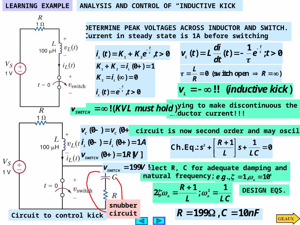
LEARNING EXAMPLEANALYSIS AND CONTROL OF “INDUCTIVE KICK”
DETERMINE PEAK VOLTAGES ACROSS INDUCTOR AND SWITCH.Current in steady state is 1A before switching
1 2( ) , 0
t
Li t K K e t
1 2
2
(0 ) 1
( ) 0
( ) , 0
L
L
t
L
K K i
K i
i t e t
0 (switch open )L
RR
1( ) ( ) ; 0
t
L
div t L t e t
dt
Circuit to control kick
!! ( )Lv inductive kick
Trying to make discontinuous theinductor current!!!
!( )SWITCHv KVL must hold
(0 ) (0 ) 0
(0 ) (0 ) 1
(0 ) 1 [ ]
C C
L L
SWITCH
v v
i i A
v R V
circuit is now second order and may oscillate
2 1 1Ch. Eq.: 0
Rs s
L LC
Select R, C for adequate damping andnatural frequency; 6. ., 1, 10
ne g
21 12 ;
n n
R
L LC
DESIGN EQS.
199 , 10R C nF
199 !SWITCHv V
snubbercircuit

Inductor current at the beginning of ON period MUST be the same than the current at the end of OFF period
LEARNING EXAMPLE BOOSTER CONVERTER
STANDARD DC POWER SUPPLY
BOOSTER “ON” PERIODEnergy is stored in inductor.Capacitor discharges
BOOSTER “OFF” PERIODInductor releases energy.Capacitor charges
e.g. booster

THE “ON” CYCLE
onin
t
LonL tL
VIdxxv
Liti
on
00
)(1
)0()(
THE “OFF” CYCLE ontt
off
on
t
tLonoffonL dxxv
Ltitti )(
1)()(
SIMPLIFYING ASSUMPTION: THE OUTPUTVOLTAGE (Vo) IS CONSTANT
0VVv inL
offin
on tL
VVtiI 0
0 )(
offin
onin
o tL
VVt
L
VII 0
0
inoff
offono V
t
ttV
booster) (hence inVV 0
T
tD
ttT
on
offon
:cycleDuty
:Period
DVV in
1
10
By adjusting the duty cycle one canadjust the output voltage level

LEARNING BY DESIGNDESIGN OF ELECTRIC HEATER USING A 24V SOURCE AND1 OHM HEATING ELEMENT
100 400W P W Solution one
Too much power lost in rheostat
SWITCHED INDUCTORALTERNATIVE
Pos 1pos 2
Controlling switching frequency one controls I_peak and average power … And no power loss!

LEARNING EXAMPLE DESIGN DECOUPLING CAPACITOR TO ISOLATE LOAD FROM VARIATION IN SUPPLY VOLTAGE
decouplingcapacitor
(0)O
VO
V
DESIGN EQUATION FOR DECOUPLING CAPACITOR
model forsupply variation
EXPECTED SPIKE
'EXPECTED DURATION
:
:S
V
t
Qualitative operation
acceptable
CIRCUIT AT t=0+ STEADY STATE AFTER SWITCHING

LEARNING BY DESIGN
1.5s and 1s between1A above Stays (2)
100ms; within1A Reaches (1)
:SATISFIES AND,OVERDAMPED IS THAT SUCH FIND )(tiC
AFTER SWITCHING WE HAVE RLC SERIES
0)(1
)()(2
2
tiLC
tdt
di
L
Rt
dt
idL
LL
0))((/520 212 ssssCss :Eq. Ch.
0;)( 2121 teKeKti tsts:RESPONSE DESIRED
Cssss /5;20 2121
12)0()0(;0)0( dt
diLvi L
LL
:CONDITIONSINITIAL
60
0
2211
21
KsKs
KK
For the initial conditions analyze circuit at t=0+. Assume the circuit was in steadystate prior to the switching
+ -
)0()0(dt
diLvL
)0(Cv Circuit at t=0+
VvC 12)0(
http://www.wiley.com/college/irwin/0470128690/animations/swf/7-21.swf
tstsL ee
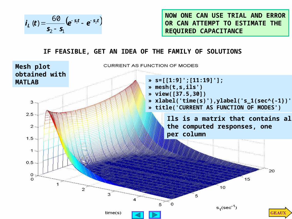
ssti 21
12
60)(
NOW ONE CAN USE TRIAL AND ERROROR CAN ATTEMPT TO ESTIMATE THEREQUIRED CAPACITANCE
Mesh plot obtained withMATLAB
IF FEASIBLE, GET AN IDEA OF THE FAMILY OF SOLUTIONS
» s=[[1:9]';[11:19]'];» mesh(t,s,ils')» view([37.5,30])» xlabel('time(s)'),ylabel('s_1(sec^{-1})')» title('CURRENT AS FUNCTION OF MODES')
Ils is a matrix that contains allthe computed responses, oneper column

%example6p14.m%displays current as function of roots in characteristic equation% il(t)=(60/(s2-s1))*(exp(-s1*t)-exp(s2*t));% with restriction s1+s2=20, s1~=s2.t=linspace(0,5,500)'; %set display interval as a column vectorils=[]; %reserve space to store curvesfor s1=1:19 s2=20-s1; if s1~=s2 il=(60/(s2-s1))*(exp(-s1*t)-exp(-s2*t)); ils=[ils il]; %save new trace as a column in matrix endend%now with one command we plot all the columns as functions of timeplot(t,ils), grid, xlabel('Time(s)'),ylabel('i(A)')title('CURRENT AS FUNCTION OF MODES')
Estimate charge by estimating area under the curve
For this curve the area is approx. 12 squares
CsAQ 3][5.05.012
mFFV
QC 25025.0
12
3
20/5
20
21
21
Css
ss
056.1
944.18
2
1
s
s

%verification s1=18.944; s2=20-s1; il=(60/(s2-s1))*(exp(-s1*t)-exp(-s2*t)); plot(t,il,'rd',t,il,'b'), grid, xlabel('time(s)'), ylabel('i(A)') title('VERIFICATION OF DESIGN')
Applications
Top Related