


Languages
Pages
Legal

L E A D I N G T H E W A Y I N C O N C R E T E P U M P I N G S Y S T E M S
1| About Us
Our Mission• To be the world leader and highest quality manufacturer of concrete pumping systems and accessories.
• To be the leading provider of abrasion resistant piping systems by developing, producing and marketing engineered products and services; focusing on satisfying the needs of selected markets including concrete pumping, mining, pulp & paper, power generation, and wastewater treatment.
• To provide consistent customer service, quality products, and timely delivery resulting in total customer satisfaction.
• To maintain a motivating and safe work environment for our employees.
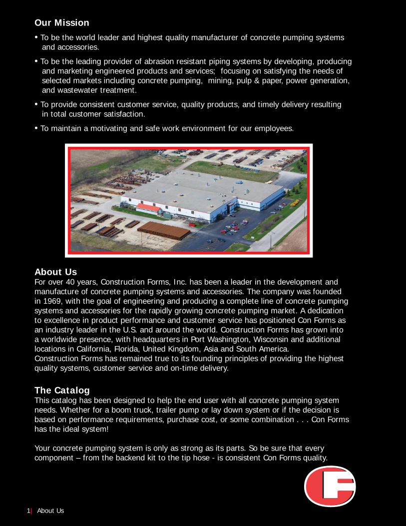
About UsFor over 40 years, Construction Forms, Inc. has been a leader in the development andmanufacture of concrete pumping systems and accessories. The company was foundedin 1969, with the goal of engineering and producing a complete line of concrete pumpingsystems and accessories for the rapidly growing concrete pumping market. A dedicationto excellence in product performance and customer service has positioned Con Forms asan industry leader in the U.S. and around the world. Construction Forms has grown intoa worldwide presence, with headquarters in Port Washington, Wisconsin and additionallocations in California, Florida, United Kingdom, Asia and South America.Construction Forms has remained true to its founding principles of providing the highestquality systems, customer service and on-time delivery.
The CatalogThis catalog has been designed to help the end user with all concrete pumping systemneeds. Whether for a boom truck, trailer pump or lay down system or if the decision isbased on performance requirements, purchase cost, or some combination . . . Con Formshas the ideal system!
Your concrete pumping system is only as strong as its parts. So be sure that everycomponent – from the backend kit to the tip hose - is consistent Con Forms quality.
DECKPIPEC
F D
N1
25
85
BA
R-1
23
3W
P 4
.9-D
IA.
CF DN125 85BAR-WP 4.9-DIA. Page 7-10
Page 11-13
Page 14-16
Page 17-20
Page 21-24
Page 25-30
Page 31
Page 33-40
Page 41-44
Page 45-46
Page 47-49
Page 50-51
BOOMELBOWS
BOOMREDUCERS
BACKENDKITS
COUPLINGS & ACCESSORIES
HOSE &ACCESSORIES
CLEAN OUTACCESSORIES
LAY DOWNSYSTEM
SYSTEMVALVES
WELD ENDS &ADAPTORS
KRETEPLACERS
SMALLLINE
MAX WP
4350 PSI300 BAR
19.5 LBS
DNWEIGHT FWCWEIGHT NETP/N NOTES
mm WPmax bar psi
Page 52-54REFERENCE DATA
Page 3-6BOOMPIPE
CF DN125 85BAR-WP 4.9-DIA.
CF
DN
125 8
5B
AR
-1233W
P 4
.9-D
IA.
DNWEIGHT FWCWEIGHT NETP/N NOTES
mm WPmax bar psi
DNWEIGHT FWCWEIGHT NETP/N NOTES
mm WPmax bar psiDNWEIGHT FWCWEIGHT NETP/N NOTES
mm WPmax bar psi
Visit us on line at www.conforms.comTable of Contents | 2
Page 32WEARPARTS

CF
DN
12
5 8
5B
AR
-WP
4.9
-DIA
. 1
25
0-P
SI
Approx.Shipping Weight
(lbs. / Kg.)Length(mm)
1000
2000
3000
4000
B48TW3937M
B48TW7875M
B48TWB812M
B48TWF750MB48TW____M
Part NumberLength
(in)
135 / 61103 / 47
70 / 32
37 /17
132 / 60100 / 45
68 / 31
36 /16
Make up length (consult factory)
39.37
78.75118.12157.50
Length(mm)
1000
2000
3000
4000
B48TWL3937M
B48TWL7875M
B48TWLB812M
B48TWLF750MB48TWL____M
Part NumberLength
(in)
Make up length (consult factory)
39.37
78.75118.12157.50
Our longest lasting DN125/5 Twin-Wall™System features a 3.00mm wear resistant pipeliner and 1.5mm steel shell, with the endshaving a chrome carbide liner to protect thepipe against excessive wear.
PRODUCT FEATURES
PRODUCT FEATURESOur most versatile DN125/5 Twin-Wall™System features a 2.00mm wear resistant pipeliner and 2.0mm steel shell, with the endshaving a hardened steel liner to protect the pipe against excessive wear.
KEY PIPE SPECIFICATIONS AT A GLANCEInduction HardenedDN125/53.00mm + 1.5mmUp to 68HRc85 bar (1233 psi)10.7 lbs/ft (15.9 kg/m)28.8 lbs/ft (43.7 kg/m)
KEY PIPE SPECIFICATIONS AT A GLANCEInduction HardenedDN125/52.5mm + 2.0mmUp to 68HRc85 bar (1233 psi)9.7 lbs/ft (14.4 kg/m)28.9 lbs/ft (42.7 kg/m)
Chrome carbide linerprotects against flowturbulence providinglonger life.
Hardened steel linerprotects against flowturbulence providinglonger life.
1.5mm shell3.00mm liner
2.0mm shell2.0mm liner
3 |Boom Pipe
TWIN-WALL™ BOOM PIPE
For additional information or to place an order, please call 800.223.3676
Boo
m P
ipe
Heat TreatmentSystemWall ThicknessHardnessWorking Pressure (max):
Pipe Weight (net):
Pipe Weight (filled with concrete):
Heat TreatmentSystemWall ThicknessHardnessWorking Pressure (max):
Pipe Weight (net):
Pipe Weight (filled with concrete):
Other lengths are available upon request. Consult factory.
Other lengths are available upon request. Consult factory.
TWIN-WALL™ BOOM TUBE (3.25mm + 1.5mm)with 148mm chrome carbide insert (CCI) weld ends
TWIN-WALL™ BOOM TUBE (2.50mm + 2.0mm)with 148mm hardened steel insert weld ends
• Twin-Wall™ Deck Pipe• CCI-Lined Deck Pipe• CCI-Lined Elbows
• CCI-Lined Reducers• CCI-Lined Backend Kit
OTHER RECOMMENDED COMPONENTSFOR A COMPLETE TW325 SYSTEM
• Twin-Wall™ Deck Pipe• CCI-Lined Deck Pipe• TW275 Elbows
• CCI-Lined Reducers• CCI-Lined Backend Kit
OTHER RECOMMENDED COMPONENTSFOR A COMPLETE TW275 SYSTEM
Approx.Shipping Weight
(lbs. / Kg.)
ASME B30.27-2014
CERTIFIEDD
CF
DN
12
5 8
5B
AR
-WP
4.9
-DIA
. 1
25
0-P
SI
CF
DN
11
2 8
5B
AR
-WP
4.4
DIA
. 1
25
0-P
SI
CF
DN
11
7 8
5B
AR
-
FLOW DIRECTION
CF
DN
11
7 8
5B
AR
-
Length(mm)
1000
2000
3000
4000
Other lengths are available upon request. Consult factory.
B46TW3937M
B46TW7875M
B46TWB812M
B46TWF750MB46TW____M
Part Number
B46TWUL3937M
B46TWUL7875M
B46TWULB812M
B46TWULF750MB46TWUL____M
Part NumberExtended End Standard EndsLength
(in)
117 / 5391 / 41
64 / 29
38 /17
Make up length (consult factory)
39.37
78.75118.12157.50
Length(mm)
1000
2000
3000
4000
Other lengths are available upon request. Consult factory.
B44TW3937M
B44TW7875M
B44TWB812M
B44TWF750MB44TW____M
Part NumberLength
(in)
110 / 5084 / 38
57 / 27
33 /15
Make up length (consult factory)
39.37
78.75118.12157.50
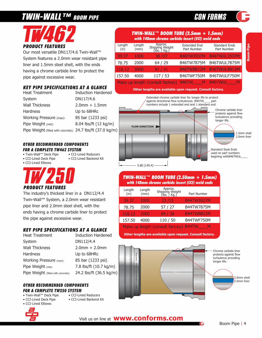
TWIN-WALL™ BOOM TUBE (2.5mm + 1.5mm)with 148mm chrome carbide insert (CCI) weld ends
TWIN-WALL™ BOOM TUBE (2.50mm + 1.5mm)with 148mm chrome carbide insert (CCI) weld ends
KEY PIPE SPECIFICATIONS AT A GLANCEInduction HardenedDN117/4.62.0mm + 1.5mmUp to 68HRc85 bar (1233 psi)8.04 lbs/ft (12 kg/m)24.7 lbs/ft (37.0 kg/m)
PRODUCT FEATURESThe industry’s thickest liner in a DN112/4.4 Twin-Wall™ System, a 2.0mm wear resistantpipe liner and 2.0mm steel shell, with theends having a chrome carbide liner to protectthe pipe against excessive wear.
KEY PIPE SPECIFICATIONS AT A GLANCE
PRODUCT FEATURESOur most versatile DN117/4.6 Twin-Wall™System features a 2.0mm wear resistant pipeliner and 1.5mm steel shell, with the endshaving a chrome carbide liner to protect the pipe against excessive wear.
Chrome carbide linerprotects against flow turbulence providinglonger life.
1.5mm shell2.0mm liner
Extended chrome carbide liner for longer life to protectagainst directional flow turbulences. B46TW____ partnumbers include 1 extended end and 1 standard end.
Visit us on line at www.conforms.comBoom Pipe | 4
TWIN-WALL™ BOOM PIPE
Boo
m P
ipe
Heat Treatment SystemWall Thickness Hardness Working Pressure (max):
Pipe Weight (net):
Pipe Weight (filled with concrete):
Heat Treatment SystemWall ThicknessHardnessWorking Pressure (max):
Pipe Weight (net):
Pipe Weight (filled with concrete):
Chrome carbide linerprotects against flow turbulence providinglonger life.
2.0mm shell2.0mm liner
• Twin-Wall™ Deck Pipe• CCI-Lined Deck Pipe• CCI-Lined Elbows
• CCI-Lined Reducers• CCI-Lined Backend Kit
OTHER RECOMMENDED COMPONENTSFOR A COMPLETE TW462 SYSTEM
• Twin-Wall™ Deck Pipe• CCI-Lined Deck Pipe• CCI-Lined Elbows
• CCI-Lined Reducers• CCI-Lined Backend Kit
OTHER RECOMMENDED COMPONENTSFOR A COMPLETE TW250 SYSTEM
Approx.Shipping Weight
(lbs. / Kg.)
Approx.Shipping Weight
(lbs. / Kg.)
Standard Style Endsused on part numbersbegining withB46TWUL____
5.88 [149.4]
Induction HardenedDN112/4.42.0mm + 2.0mmUp to 68HRc85 bar (1233 psi)7.8 lbs/ft (10.7 kg/m)24.2 lbs/ft (36.5 kg/m)
CONFORMS 4.9-DIA SUPER 7 GAUGE 29.5-lb/ft
Chrome carbideprotects againstflow turbulenceproviding longer life.
.188 / 4.8mmwall
CONFORMS 4.9-DIA SUPER 7 GAUGE 29.5-lb/ft
Chrome carbideprotects againstflow turbulenceproviding longer life.
.188 / 4.8mmwall
Weld sleeve
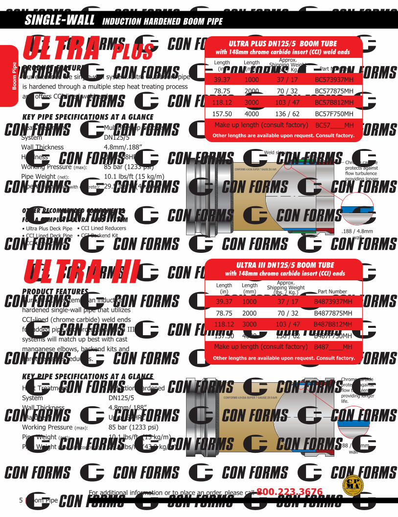
39.37 1000 37 / 17 BC573937MH
78.75 2000 70 / 32 BC577875MH
118.12 3000 103 / 47 BC57B812MH
157.50 4000 136 / 62 BC57F750MH
BC57____MHMake up length (consult factory)
Approx.Shipping Weight
(lbs. / Kg.)Length(mm) Part Number
Length(in)
Our extended life single-wall system. Ultra Plus boom pipeis hardened through a multiple step heat treating processand offers CCI-lined weld ends.
PRODUCT FEATURES
KEY PIPE SPECIFICATIONS AT A GLANCE
ULTRA PLUS
5 |Boom Pipe
SINGLE-WALL INDUCTION HARDENED BOOM PIPE
For additional information or to place an order, please call 800.223.3676
Boo
m P
ipe
Multiple step processDN125/54.8mm/.188” Up to 68HRc85 bar (1233 psi)10.1 lbs/ft (15 kg/m)29.5 lbs/ft (43.9 kg/m)
Heat TreatmentSystemWall ThicknessHardnessWorking Pressure (max):
Pipe Weight (net):
Pipe Weight (filled with concrete):
Other lengths are available upon request. Consult factory.
ULTRA PLUS DN125/5 BOOM TUBEwith 148mm chrome carbide insert (CCI) weld ends
ULTRA III39.37 1000 37 / 17 B4873937MH
78.75 2000 70 / 32 B4877875MH
118.12 3000 103 / 47 B487B812MH
157.50 4000 136 / 62 B487F750MH
B487____MHMake up length (consult factory)
Our Ultra III system is an inductionhardened single-wall pipe that utilizesCCI-lined (chrome carbide) weld endsfor added pipe end protection. Ultra IIIsystems will match up best with castmanganese elbows, backend kits andhardened steel reducers.
PRODUCT FEATURES
KEY PIPE SPECIFICATIONS AT A GLANCE
Approx.Shipping Weight
(lbs. / Kg.)Length(mm) Part Number
Length(in)
Heat TreatmentSystem Wall Thickness Hardness Working Pressure (max):
Pipe Weight (net):
Pipe Weight (filled with concrete):
Induction hardenedDN125/54.8mm/.188”Up to 57HRc85 bar (1233 psi)10.1 lbs/ft (15 kg/m)29.5 lbs/ft (43.9 kg/m)
ULTRA III DN125/5 BOOM TUBEwith 148mm chrome carbide insert (CCI) ends
Other lengths are available upon request. Consult factory.
• CCI Lined Deck Pipe• Ultra Plus Deck Pipe
• CCI Lined Elbows
• CCI Lined Reducers• CCI Backend Kit
OTHER RECOMMENDED COMPONENTSFOR A COMPLETE ULTRA PLUS SYSTEM
ASME B30.27-2014
CERTIFIEDD

CONFORMS 4.9-DIA SUPER 7 GAUGE 29.5-lb/ft
Non-hardenedweld end
.188 / 4.8mm wall
CONFORMS 4.9-DIA SUPER 7 GAUGE 29.5-lb/ft
Hardened Steel linerfor longer life to protectagainst flow turbulences
.188 / 4.8mm wall
Visit us on line at www.conforms.comBoom Pipe | 6
SINGLE-WALL INDUCTION HARDENED BOOM PIPE
Boo
m P
ipe
B5073937MH
B5077875MH
B507B812MH
B507F750MH
B507____MH
B5073937M
B5077875M
B507B812M
B507F750M
B507____M
39.37 1000
78.75 2000
118.12 3000
157.50 4000
39.37 1000
78.75 2000
118.12 3000
157.50 4000
Make up length (consult factory)
Make up length (consult factory)
Length(mm)
Other lengths are available upon request. Consult factory.
Part NumberLength
(in)
ULTRA II DN125/5 BOOM TUBEwith 148mm hardened steel weld end liners.
Our heat treated Single Wall system,utilizing hardened steel lined weld ends with cast manganese elbows, backendkits and hardened steel reducers.
PRODUCT FEATURES
Our least expensive non-heat treated single-wall system. Not designed fordemanding applications or long life requirements.
PRODUCT FEATURES
XL-92 DN125/5 BOOM TUBEwith 148mm steel weld ends
Length(mm) Part Number
Length(in)
Other lengths are available upon request. Consult factory.
KEY PIPE SPECIFICATIONS AT A GLANCENon-heat treatedDN125/54.8mm/.188”None85 bar (1233 psi)10.1 lbs/ft (15 kg/m)29.5 lbs/ft (43.9 kg/m)
KEY PIPE SPECIFICATIONS AT A GLANCEHeat TreatmentSystemWall ThicknessHardnessWorking Pressure (max):
Pipe Weight (net):
Pipe Weight (filled with concrete):
ULTRA II
XL-92
Heat Treatment SystemWall ThicknessHardnessWorking Pressure (max):
Pipe Weight (net):
Pipe Weight (filled with concrete):
Induction hardenedDN125/54.8mm/.188”Up to 57HRc85 bar (1233 psi)10.1 lbs/ft (15 kg/m)29.5 lbs/ft (43.9 kg/m)
• Ultra II Deck Pipe• Cast Manganese Elbows• Hardened Steel Reducers• Hardened, Cast Steel Backend Kit
OTHER RECOMMENDED COMPONENTSFOR A COMPLETE ULTRA III & ULTRA II SYSTEMS
• XL-92 Deck Pipe• Cast Manganese Elbows• Single-wall Steel Reducers• Hardened, Cast Steel Backend Kit
OTHER RECOMMENDED COMPONENTSFOR A COMPLETE XL-92 SYSTEM
37 / 17
70 / 32
103 /47
136 / 62
Approx.Shipping Weight
(lbs. / Kg.)
37 / 17
70 / 32
103 /47
136 / 62
Approx.Shipping Weight
(lbs. / Kg.)
CF DN
125 8
5BAR
-WP 4
.8 DIA
. 125
0 PSI
37 LB
/FT FW
C Chrome carbide linerfor longer life to protectagainst flow turbulences
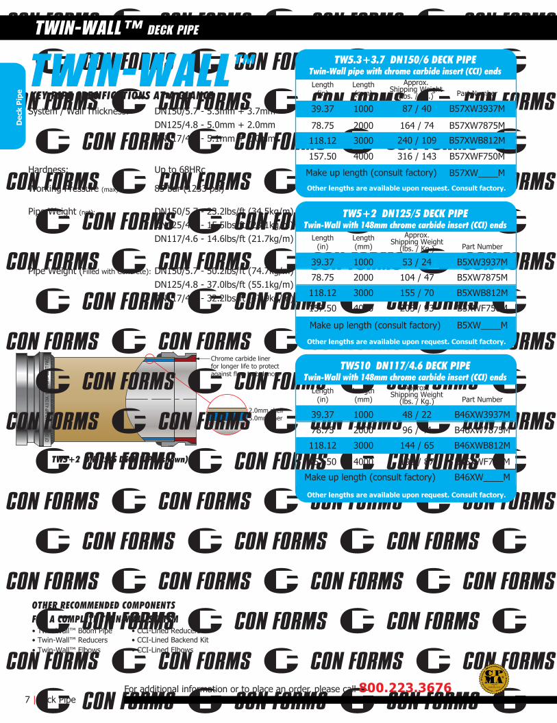
2.0mm shell5.0mm liner
TW5+2 DN125/5 DECK PIPE (shown)
7 |Deck Pipe
TWIN-WALL™ DECK PIPE
For additional information or to place an order, please call 800.223.3676
Dec
k P
ipe KEY PIPE SPECIFICATIONS AT A GLANCE
39.37 1000
78.75 2000
118.12 3000
157.50 4000
39.37 1000
78.75 2000
118.12 3000
157.50 4000
Other lengths are available upon request. Consult factory.
Other lengths are available upon request. Consult factory.
48 / 22 B46XW3937M
96 / 44 B46XW7875M
144 / 65 B46XWB812M
192 / 87 B46XWF750M
B46XW____M
53 / 24 B5XW3937M
104 / 47 B5XW7875M
155 / 70 B5XWB812M
205 / 93 B5XWF750M
78.75 2000
157.50 4000
164 / 74 B57XW7875M
316 / 143 B57XWF750M
B5XW____M
Length(mm)
Part Number
Part NumberLength
(in)
Length(mm)
Length(in)
Make up length (consult factory)
Make up length (consult factory)
TW510 DN117/4.6 DECK PIPETwin-Wall with 148mm chrome carbide insert (CCI) ends
TW5+2 DN125/5 DECK PIPETwin-Wall with 148mm chrome carbide insert (CCI) ends
39.37 1000
118.12 3000
Other lengths are available upon request. Consult factory.
87 / 40 B57XW3937M
240 / 109 B57XWB812M
B57XW____M
Length(mm) Part Number
Length(in)
Make up length (consult factory)
TW5.3+3.7 DN150/6 DECK PIPETwin-Wall pipe with chrome carbide insert (CCI) endsTWIN-WALL
System / Wall Thickness:
Pipe Weight (net):
Pipe Weight (Filled with Concrete):
Working Pressure (max):
Hardness:
DN150/5.7 - 5.3mm + 3.7mm DN125/4.8 - 5.0mm + 2.0mmDN117/4.6 - 5.1mm + 2.0mm
Up to 68HRc
85 bar (1233 psi)
DN150/5.7 - 23.2lbs/ft (34.5kg/m)DN125/4.8 - 15.5lbs/ft (23.1kg/m)DN117/4.6 - 14.6lbs/ft (21.7kg/m)
DN150/5.7 - 50.2lbs/ft (74.7kg/m)DN125/4.8 - 37.0lbs/ft (55.1kg/m)DN117/4.6 - 32.2lbs/ft (47.9kg/m)
• Twin-Wall™ Boom Pipe• Twin-Wall™ Reducers• Twin-Wall™ Elbows
• CCI-Lined Reducers• CCI-Lined Backend Kit• CCI-Lined Elbows
OTHER RECOMMENDED COMPONENTSFOR A COMPLETE TWIN-WALL SYSTEM
™Approx.
Shipping Weight(lbs. / Kg.)
Approx.Shipping Weight
(lbs. / Kg.)
Approx.Shipping Weight
(lbs. / Kg.)
ASME B30.27-2014
CERTIFIEDD
DNWEIGHT FWCWEIGHT NETP/N NOTES
mm bar psiWPmax
Chrome carbide linerfor longer life to protectagainst flow turbulences
3.0mm shell7.5mm liner
DN125/5 DECK PIPE SHOWN
Visit us on line at www.conforms.comDeck Pipe | 8
CHROME CARBIDE LINED DECK PIPE
Dec
k P
ipe
Length(mm)
Other lengths and weldends are available upon request.Consult factory.
Part NumberLength
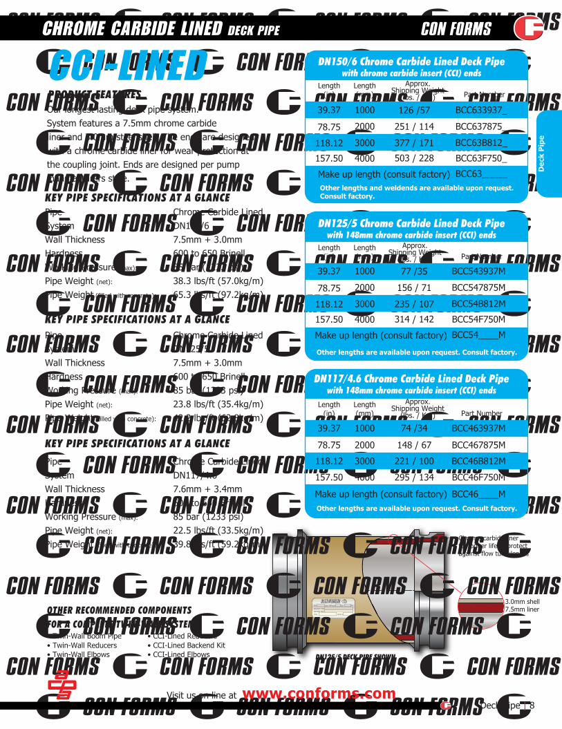
(in)PRODUCT FEATURESOur longest lasting deck pipe system.System features a 7.5mm chrome carbideliner and 3.0mm steel shell. The ends are designedwith a chrome carbide liner for wear protection atthe coupling joint. Ends are designed per pumpmanufacturers style.
DN150/6 Chrome Carbide Lined Deck Pipewith chrome carbide insert (CCI) ends
Length(mm)
1000
2000
3000
4000
Other lengths are available upon request. Consult factory.
BCC543937M
BCC547875M
BCC54B812M
BCC54F750M
BCC54____M
Part NumberLength
(in)
314 / 142
235 / 107
156 / 71
77 /35
Make up length (consult factory)
39.37
78.75
118.12
157.50
DN125/5 Chrome Carbide Lined Deck Pipewith 148mm chrome carbide insert (CCI) ends
Length(mm)
1000
2000
3000
4000
Other lengths are available upon request. Consult factory.
BCC463937M
BCC467875M
BCC46B812M
BCC46F750M
BCC46____M
Part NumberLength
(in)
295 / 134
221 / 100
148 / 67
74 /34
Make up length (consult factory)
39.37
78.75
118.12
157.50
DN117/4.6 Chrome Carbide Lined Deck Pipewith 148mm chrome carbide insert (CCI) ends
KEY PIPE SPECIFICATIONS AT A GLANCEChrome Carbide Lined DN150/67.5mm + 3.0mm600 to 650 Brinell85 bar (1233 psi)38.3 lbs/ft (57.0kg/m)65.3 lbs/ft (97.2kg/m)
KEY PIPE SPECIFICATIONS AT A GLANCEChrome Carbide Lined DN125/57.5mm + 3.0mm600 to 650 Brinell85 bar (1233 psi)23.8 lbs/ft (35.4kg/m)42.2 lbs/ft (62.8kg/m)
KEY PIPE SPECIFICATIONS AT A GLANCE
Chrome Carbide Lined DN117/4.67.6mm + 3.4mm600 to 650 Brinell85 bar (1233 psi)22.5 lbs/ft (33.5kg/m)39.8 lbs/ft (59.2kg/m)
CCI-LINED1000
2000
3000
4000
BCC633937_
BCC637875_
BCC63B812_
BCC63F750_
BCC63_____
503 / 228
377 / 171
251 / 114
126 /57
Make up length (consult factory)
39.37
78.75
118.12
157.50
PipeSystemWall Thickness Hardness Working Pressure (max):
Pipe Weight (net):
Pipe Weight (filled with concrete):
Pipe SystemWall Thickness Hardness Working Pressure (max):
Pipe Weight (net):
Pipe Weight (filled with concrete):
Pipe SystemWall Thickness HardnessWorking Pressure (max):
Pipe Weight (net):
Pipe Weight (filled with concrete):
• Twin-Wall Boom Pipe• Twin-Wall Reducers• Twin-Wall Elbows
• CCI-Lined Reducers• CCI-Lined Backend Kit• CCI-Lined Elbows
OTHER RECOMMENDED COMPONENTSFOR A COMPLETE TWIN-WALL SYSTEM
Approx.Shipping Weight
(lbs. / Kg.)
Approx.Shipping Weight
(lbs. / Kg.)
Approx.Shipping Weight
(lbs. / Kg.)

CONFORMS 4.9-DIA DECK-PIPE 33.5-lb/ft
Chrome carbide linerfor longer life to protectagainst flow turbulences
.261 / 6.6mmwall
CONFORMS 4.9-DIA DECK-PIPE 33.5-lb/ft
Chrome carbide linerfor longer life to protectagainst flow turbulences
.261 / 6.6mmwall
9 |Deck Pipe
SINGLE-WALL INDUCTION HARDENED DECK PIPE
For additional information or to place an order, please call 800.223.3676
Dec
k P
ipe
Heat Treatment
SystemWall Thickness (nominal)
Hardness Working Pressure (max): Pipe Weight (net): Pipe Weight (filled with concrete):
Heat Treatment System Wall Thickness (nominal) Hardness Working Pressure (max): Pipe Weight (net):
Pipe Weight (filled with concrete):
Multiple step processDN125/5.261/6.6mmUp to 68HRc85 bar (1233 psi)14.2 lbs/ft (21.1 kg/m)33.5 lbs/ft (49.8 kg/m)
Induction hardenedDN125/5.261/6.6mmUp to 57HRc85 bar (1233 psi)14.2 lbs/ft (21.1 kg/m)33.5 lbs/ft (49.8 kg/m)
49 / 22 BC543937MH
96 / 44 BC547875MH
143 / 65 BC54B812MH
189 / 86 BC54F750MHBC54____MH
B4843937MHB4847875MHB484B812MH
B484F750MH
B484____MH
39.37 100078.75 2000118.12 3000
157.50 4000
Make up length (consult factory)
39.37 1000
78.75 2000
118.12 3000
157.50 4000Make up length (consult factory)
Length(mm)
Other lengths are available upon request. Consult factory.
Other lengths are available upon request. Consult factory.
Part NumberLength
(in)
Our extended life single-wall system.Ultra Plus boom and deck pipe is hardenedthrough a multiple step heat treating process and offers CCI-lined weld ends, elbows, reducers and backend kits.
PRODUCT FEATURES
ULTRA PLUS DN125/5 DECK PIPEwith 148mm chrome carbide insert (CCI) ends
Length(mm) Part Number
Length(in)
ULTRA III DN125/5 DECK PIPEwith 148mm chrome carbide insert (CCI) ends
KEY PIPE SPECIFICATIONS AT A GLANCE
KEY PIPE SPECIFICATIONS AT A GLANCE
ULTRA PLUS
Our heat treated single-wall system,utilizing CCI-lined weld ends with castmanganese elbows, backend kits andhardened steel reducers.
PRODUCT FEATURES
ULTRA III• Ultra Plus Boom Pipe• CCI Lined Elbows
• CCI Lined Reducers• CCI Backend Kit
OTHER RECOMMENDED COMPONENTSFOR A COMPLETE ULTRA PLUS SYSTEM
• Ultra III Boom Pipe• Cast Manganese Elbows
• Hardened Steel Reducers• Hardened, Cast Steel Backend Kit
OTHER RECOMMENDED COMPONENTSFOR A COMPLETE ULTRA III SYSTEM
Approx.Shipping Weight
(lbs. / Kg.)
Approx.Shipping Weight
(lbs. / Kg.)
49 / 22
96 / 44
143 / 65189 / 86
ASME B30.27-2014
CERTIFIEDD

CONFORMS 4.9-DIA DECK-PIPE 33.5-lb/ft
.261 / 6.6mmwall
CONFORMS 4.9-DIA DECK-PIPE 33.5-lb/ft
.261 / 6.6mmwall
Heat treatedweld end
Visit us on line at www.conforms.comDeck Pipe | 10
SINGLE-WALL INDUCTION HARDENED DECK PIPE
Dec
k P
ipe
B5043937MH
B5047875MH
B504B812MHB504F750MH
B504____MH
B5043937MB5047875M
B504B812M
B504F750MB504____M
39.37 1000
78.75 2000
118.12 3000157.50 4000
Make up length (consult factory)
39.37 100078.75 2000
118.12 3000
157.50 4000Make up length (consult factory)
Approx.Shipping Weight
(lbs. / Kg.)Length(mm) Part Number
Length(in)
Approx.Shipping Weight
(lbs. / Kg.)Length(mm) Part Number
Length(in)
Our heat treated single-wall system,utilizing hardened steel weld ends with cast manganese elbows, backendkits and hardened steel reducers.
PRODUCT FEATURES
Our least expensive non-heat treatedsingle-wall system. Not designed fordemanding applications or long liferequirements.
PRODUCT FEATURES
• XL-92 Boom Pipe• Cast Manganese Elbows• Hardened Steel Reducers• Hardened, Cast Steel Backend Kit
• Ultra II Boom Pipe• Cast Manganese Elbows• Hardened Steel Reducers• Hardened, Cast Steel Backend Kit
OTHER RECOMMENDED COMPONENTSFOR A COMPLETE ULTRA II SYSTEM
OTHER RECOMMENDED COMPONENTSFOR A COMPLETE XL-92/ST-52 SYSTEM
ULTRA II
XL-92
Heat TreatmentSystem IDWall Thickness (nominal)
HardnessWorking Pressure (max):
Pipe Weight (net):
Pipe Weight (filled with concrete):
KEY PIPE SPECIFICATIONS AT A GLANCE
Heat TreatmentSystem IDWall Thickness (nominal) Hardness Working Pressure (max): Pipe Weight (net):
Pipe Weight (filled with concrete):
KEY PIPE SPECIFICATIONS AT A GLANCE
Induction hardenedDN125/5.261/6.6mmUp to 57HRc85 bar (1233 psi)14.2 lbs/ft (21.1 kg/m)33.5 lbs/ft (49.8 kg/m)
Non-hardenedDN125/5.261/6.6mmN/A85 bar (1233 psi)14.2 lbs/ft ( 21.1 kg/m)33.5 lbs/ft (49.8 kg/m)
Other lengths are available upon request. Consult factory.
Other lengths are available upon request. Consult factory.
ULTRA II DN125/5 ID DECK PIPEwith 148mm Hardened steel weld ends
XL-92 / ST52 DN125/5 ID DECK PIPEwith 148mm Non-Hardened weld ends
49 / 22
96 / 44
143 / 65
189 / 86
49 / 22
96 / 44
143 / 65
189 / 86
ELBOWS WITH EXTENSIONSELBOWS WITH OR WITHOUT FINS
DNWEIGHT FWCWEIGHT NETP/N NOTES
mm bar psiWPmax
DNWEIGHT FWCWEIGHT NETP/N NOTES
mm bar psiWPmax
DNWEIGHT FWCWEIGHT NETP/N NOTES
mm bar psiWPmax
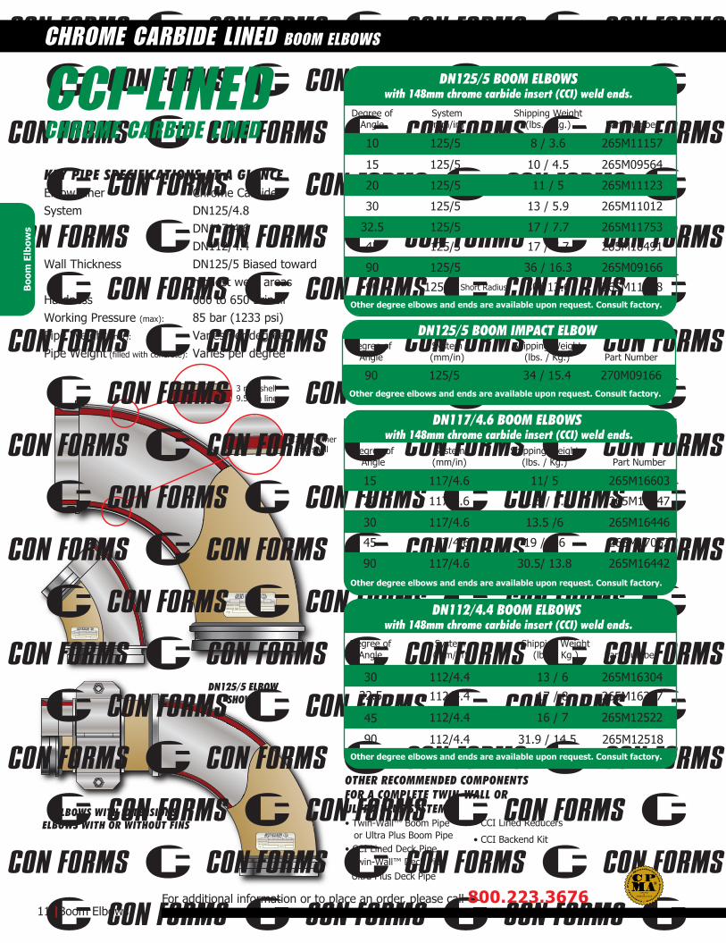
3 mm shell9.5mm liner
6.35mm liner3 mm shell
DN125/5 ELBOWSHOWN
15 125/5 10 / 4.5 265M09564
10 125/5 8 / 3.6 265M11157
20 125/5 11 / 5 265M11123
30 125/5 13 / 5.9 265M11012
32.5 125/5 17 / 7.7 265M11753
45 125/5 17 / 7.7 265M10491
90 125/5 36 / 16.3 265M09166
90 125/5 30/ 13.6 265M11158
112/4.4 13 / 6 265M16304
112/4.4 17 / 8 265M16387
45
32.530
112/4.4 16 / 7 265M12522
90 112/4.4 31.9 / 14.5 265M12518
• Twin-Wall™ Boom Pipe or Ultra Plus Boom Pipe• CCI Lined Deck Pipe
Twin-Wall™ Deck PipeUltra Plus Deck Pipe
• CCI Lined Reducers
• CCI Backend Kit
OTHER RECOMMENDED COMPONENTSFOR A COMPLETE TWIN-WALL ORULTRA PLUS SYSTEM
Shipping Weight(lbs. / Kg.)
System(mm/in)
Degree ofAngle Part Number
Shipping Weight(lbs. / Kg.)
System(mm/in)
Degree ofAngle Part Number
15 117/4.6 11/ 5 265M16603
20 117/4.6 11.5 / 5.2 265M16447
30 117/4.6 13.5 /6 265M16446
45 117/4.6 19 / 8.6 265M17062
90 117/4.6 30.5/ 13.8 265M16442
Shipping Weight(lbs. / Kg.)
System(mm/in)
Degree ofAngle Part Number
KEY PIPE SPECIFICATIONS AT A GLANCEChrome CarbideDN125/4.8DN117/4.6DN112/4.4DN125/5 Biased towardhighest wear areas600 to 650 Brinell85 bar (1233 psi)Varies per degreeVaries per degree
11 |Boom Elbows
CHROME CARBIDE LINED BOOM ELBOWS
For additional information or to place an order, please call 800.223.3676
Boo
m E
lbow
s
CCI-LINEDCHROME CARBIDE LINED
Elbow LinerSystem
Wall Thickness
HardnessWorking Pressure (max):
Pipe Weight (net):
Pipe Weight (filled with concrete):
Other degree elbows and ends are available upon request. Consult factory.
Other degree elbows and ends are available upon request. Consult factory.
DN125/5 BOOM ELBOWSwith 148mm chrome carbide insert (CCI) weld ends.
Other degree elbows and ends are available upon request. Consult factory.
DN117/4.6 BOOM ELBOWS with 148mm chrome carbide insert (CCI) weld ends.
DN112/4.4 BOOM ELBOWS with 148mm chrome carbide insert (CCI) weld ends.
Short Radius
90 125/5 34 / 15.4 270M09166
Shipping Weight(lbs. / Kg.)
System(mm/in)
Degree ofAngle Part Number
Other degree elbows and ends are available upon request. Consult factory.
DN125/5 BOOM IMPACT ELBOW
ASME B30.27-2014
CERTIFIEDD
DNWEIGHT FWCWEIGHT NETP/N NOTES
mm WPmax bar psi
DNWEIGHT FWCWEIGHT NETP/N NOTES
mm WPmax bar psi
3 mm shell9.5mm liner
3 mm shell6.35mm liner
ELBOWS WITH EXTENSIONSELBOWS WITH OR WITHOUT FINS
DNWEIGHT FWCWEIGHT NETP/N NOTES
mm WPmax bar psi
• TW275 Boom Pipe
• Deck Pipe: Twin- Wall™ or CCI-Lined
• CCI Lined Reducers
• CCI Backend Kit
• Twin-Wall™ Reducers
• Twin-Wall™ Backend Elbows
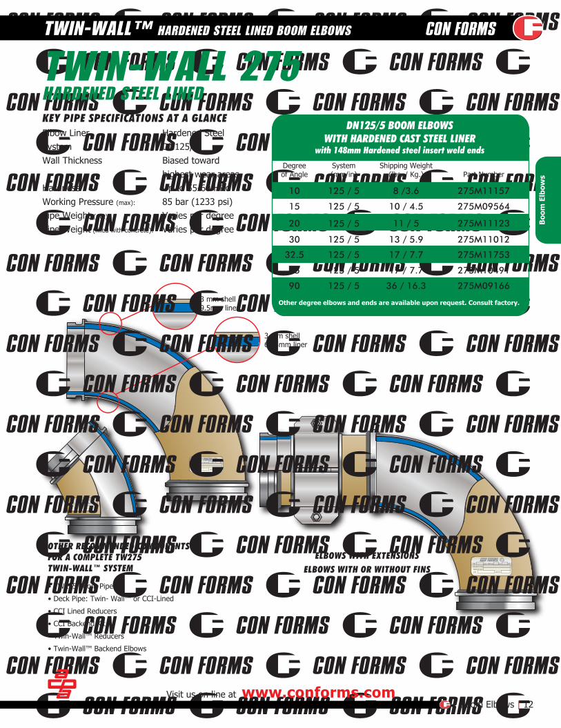
15 125 / 5
125 / 5
125 / 5
125 / 5
125 / 5
125 / 5
10 / 4.5 275M09564
10 125 / 5 8 /3.6 275M11157
20 11 / 5 275M11123
30 13 / 5.9 275M11012
32.5 17 / 7.7 275M11753
45 17 / 7.7 275M10491
90 36 / 16.3 275M09166
Shipping Weight(lbs. / Kg.)
System(mm/in) Part Number
Degreeof Angle
OTHER RECOMMENDED COMPONENTSFOR A COMPLETE TW275TWIN-WALL™ SYSTEM
TWIN-WALL 275HARDENED STEEL LINEDKEY PIPE SPECIFICATIONS AT A GLANCE
Hardened SteelDN125/5Biased towardhighest wear areasUp to 55-60 HRc85 bar (1233 psi)Varies per degreeVaries per degree
Visit us on line at www.conforms.comBoom Elbows | 12
TWIN-WALL™ HARDENED STEEL LINED BOOM ELBOWS
Boo
m E
lbow
s
Elbow LinerSystemWall Thickness
HardnessWorking Pressure (max):
Pipe Weight (net):
Pipe Weight (filled with concrete):
Other degree elbows and ends are available upon request. Consult factory.
DN125/5 BOOM ELBOWSWITH HARDENED CAST STEEL LINER
with 148mm Hardened steel insert weld ends

CAST MANGANESEwith machined 148mm Metric ends
DNWEIGHT FWCWEIGHT NETP/N NOTES
mm WPmax bar psi
CAST STEELwith
148mm Metric endswith CCI-inserts
•Single wall Boom Pipe (Ultra III, II and XL92)
•Single wall Deck Pipe (Ultra III, II and XL92)
•Hardened Steel Reducers
•Hardened, Cast Steel Backend Kit
Shipping Weight(lbs. / Kg.)
System(mm/in) Part Number
Degreeof Angle
Shipping Weight(lbs. / Kg.)
System(mm/in) Part Number
Degreeof Angle
Shipping Weight(lbs. / Kg.)
System(mm/in) Part NumberDescription
Degreeof Angle
KEY PIPE SPECIFICATIONS AT A GLANCE
KEY PIPE SPECIFICATIONS AT A GLANCE
OTHER RECOMMENDED COMPONENTSFOR A COMPLETE ULTRA III, ULTRA IIOR XL-92 SYSTEM
CASTMANGANESE
From 5° to 90°DN125/5Biased towardhighest wear areas85 bar (1233 psi)Varies per degreeVaries per degree
CASTSTEEL
From 5° to 90°DN125/5Biased towardhighest wear areas40 to 45 HRc85 bar (1233 psi)Varies per degreeVaries per degree
13 |Boom Elbows
BOOM ELBOWS
For additional information or to place an order, please call 800.223.3676
15 125 / 5
20 125 / 5
125 / 5
125 / 5
125 / 5
125 / 5
11/5 127P11123
30 11.5/5 127P11012
32.5 18/8.2 127P11753
45 18/8.2 127P11136
90 34/15 127P09166
9/4 127P09564
Hevi-Duty ends
Short Rad. / Metric ends
125 / 590 37/16.8 127P11050
125 / 590 27/12.2 127P11158
15 10/4.5 127M09564H
20 11/5 127M11123H
30 15/7 127M11012H
32.5 23/10 127M11753H
45 125 / 5
125 / 5
125 / 5
125 / 5
125 / 5
19/9 127M10491H
Boo
m E
lbow
s
Elbow Bend AnglesSystemWall Thickness
Working Pressure (max):
Pipe Weight (net):
Pipe Weight (filled with concrete):
Elbow Bend AnglesSystemWall Thickness HardnessWorking Pressure (max):
Pipe Weight (net):
Pipe Weight (filled with concrete):
DN125/5 CAST MANGANESE BOOM ELBOWSwith machined 148mm Metric ends
DN125/5 CAST MANGANESE BOOM ELBOWS
Shipping Weight(lbs. / Kg.)
System(mm/in) Part NumberDescription
Degreeof Angle
148mm ends112/4.490 32/14.5 127-19140
DN112/4.4 CAST MANGANESE BOOM ELBOWSwith machined ends and chrome carbide inserts on ends
DN125/5 BOOM ELBOWS - HARDENED CAST STEELwith 148mm chrome carbide insert (CCI) ends
Other weld ends and bend angles are available upon request.
Other weld ends and bend angles are available upon request.
90 125 / 5 34 / 15.4 127P17660
Shipping Weight(lbs. / Kg.)
System(mm/in)
Degree ofAngle Part Number
DN125/5 CAST BOOM IMPACT ELBOW
ASME B30.27-2014
CERTIFIEDD
DNWEIGHT FWCWEIGHT NETP/N NOTES
mm WPmax bar psi
•Twin-Wall™ Boom Pipe or Ultra Plus Boom Pipe
•CCI Lined Deck Pipe or Twin-Wall™ Deck Pipe or Ultra Plus Deck Pipe
•CCI Lined Elbows
•CCI Backend Kit
OTHER RECOMMENDED COMPONENTSFOR A COMPLETE TWIN-WALL™ ORULTRA PLUS SYSTEM
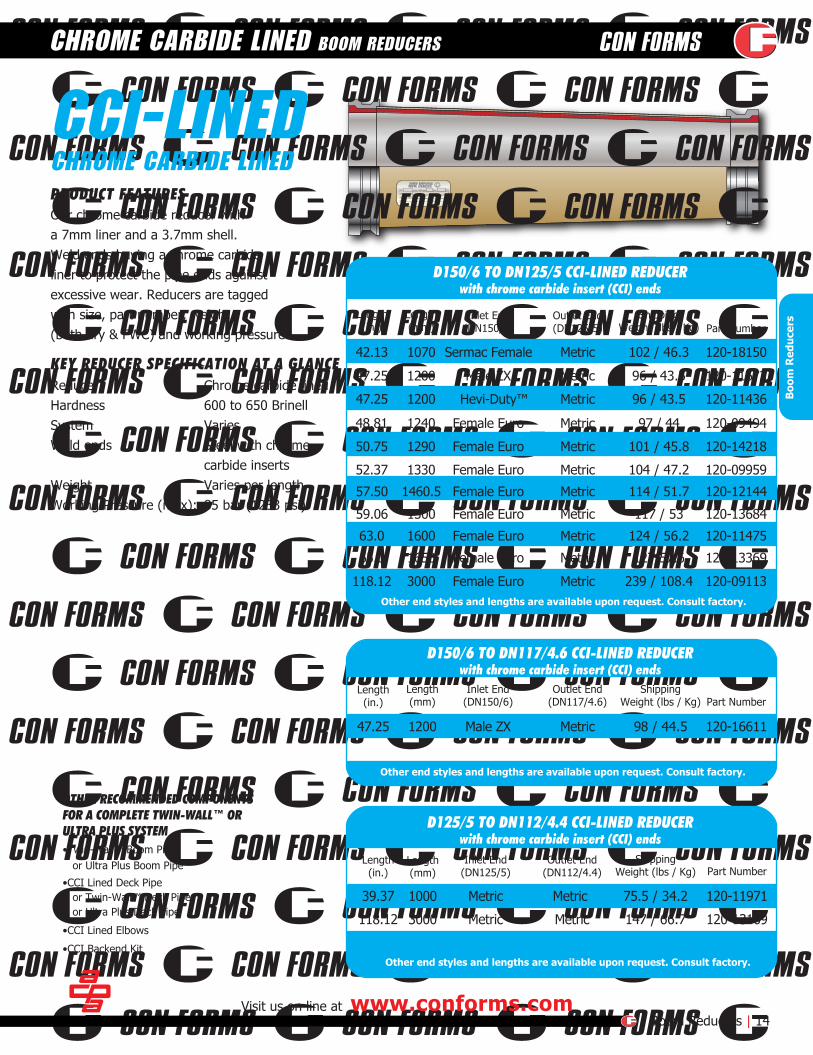
Our chrome carbide reducer witha 7mm liner and a 3.7mm shell.Weld ends having a chrome carbideliner to protect the pipe ends againstexcessive wear. Reducers are taggedwith size, part number, weight(both dry & FWC) and working pressure.
PRODUCT FEATURES
Length(in.)
Length(mm)
Outlet End(DN125/5)
Inlet End(DN150/6)
ShippingWeight (lbs / Kg) Part Number
Length(in.)
Length(mm)
Outlet End(DN117/4.6)
Inlet End(DN150/6)
ShippingWeight (lbs / Kg) Part Number
CCI-LINEDCHROME CARBIDE LINED
KEY REDUCER SPECIFICATION AT A GLANCEReducerHardnessSystem Weld ends
WeightWorking Pressure (max):
Visit us on line at www.conforms.comBoom Reducers | 14
CHROME CARBIDE LINED BOOM REDUCERS
47.25 1200 Male ZX Metric 96 / 43.5 120-11673
48.81 1240 Female Euro Metric 97 / 44 120-09494
50.75 1290 Female Euro Metric 101 / 45.8 120-14218
52.37 1330 Female Euro Metric 104 / 47.2 120-09959
63.0 1600 Female Euro Metric 124 / 56.2 120-11475
118.12 3000 Female Euro Metric 239 / 108.4 120-09113
47.25 1200 Male ZX Metric 98 / 44.5 120-16611
39.37 1000 Metric Metric 75.5 / 34.2 120-11971
118.12 3000 Metric Metric 147 / 66.7 120-13169
Length(in.)
Length(mm)
Outlet End(DN112/4.4)
Inlet End(DN125/5)
ShippingWeight (lbs / Kg) Part Number
Boo
m R
educ
ers
Chrome carbide lined600 to 650 BrinellVariesSteel with chromecarbide insertsVaries per length85 bar (1233 psi)
D150/6 TO DN125/5 CCI-LINED REDUCERwith chrome carbide insert (CCI) ends
Other end styles and lengths are available upon request. Consult factory.
Other end styles and lengths are available upon request. Consult factory.
D150/6 TO DN117/4.6 CCI-LINED REDUCERwith chrome carbide insert (CCI) ends
D125/5 TO DN112/4.4 CCI-LINED REDUCERwith chrome carbide insert (CCI) ends
Other end styles and lengths are available upon request. Consult factory.
65.0 1650 Female Euro Metric 127/57.6 120-13369
59.06 1500 Female Euro Metric 117 / 53 120-13684
57.50 1460.5 Female Euro Metric 114 / 51.7 120-12144
47.25 1200 Hevi-Duty™ Metric 96 / 43.5 120-11436
42.13 1070 Sermac Female Metric 102 / 46.3 120-18150
DNWEIGHT FWCWEIGHT NETP/N NOTES
mm WPmax bar psi
15 |Boom ReducersFor additional information or to place an order, please call 800.223.3676
Female Schwing Metric65.0 1650 123 / 55.8 113-13369
63.0 1600 Metric 118 / 53.5 113-18723H
•Twin-Wall™ Boom Pipe or Ultra plus Boom Pipe
•CCI Lined Deck Pipe or Twin-Wall™ Deck Pipe or Ultra Plus Deck Pipe
•CCI Lined Elbows•TW275 Twin-Wall™ Elbows
•CCI Backend Kit
OTHER RECOMMENDED COMPONENTSFOR A COMPLETE TWIN-WALL™ ORULTRA PLUS SYSTEM
Outlet End(DN125/5)
Inlet End(DN150/6)
Shipping Weight(lbs. / Kg.)
Length(mm) Part Number
Length(in)
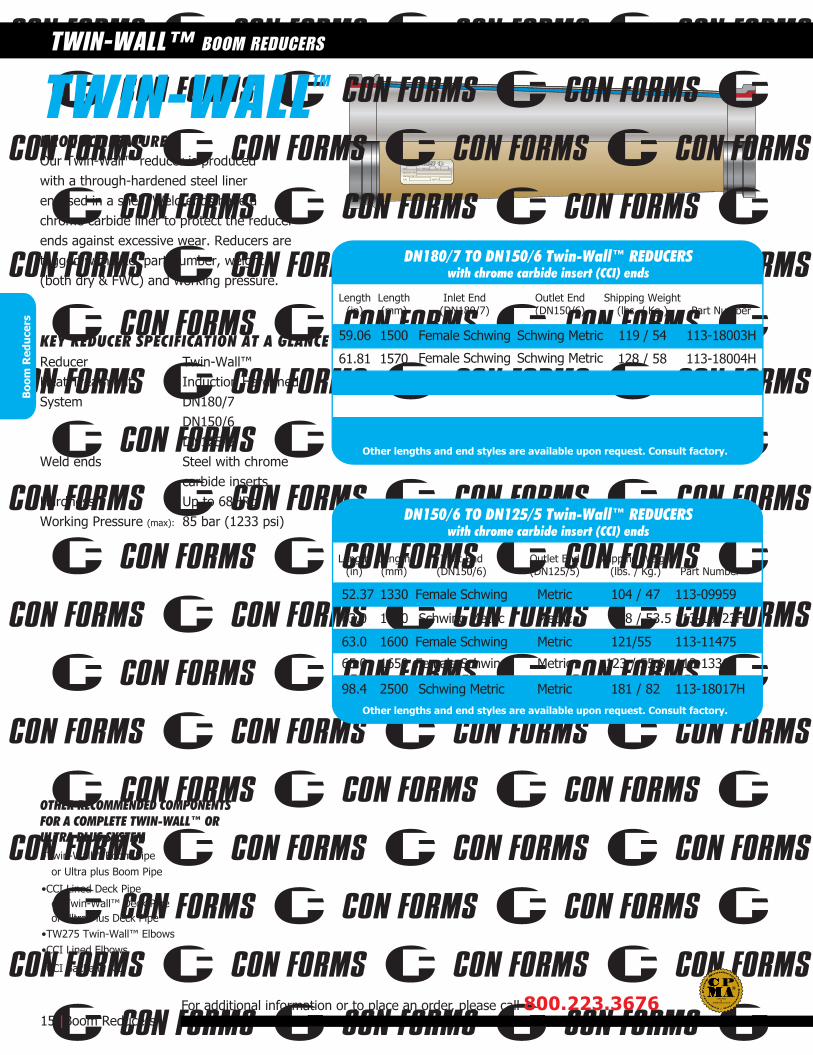
Our Twin-Wall™ reducer is producedwith a through-hardened steel linerencased in a shell. Weld ends have achrome carbide liner to protect the reducerends against excessive wear. Reducers aretagged with size, part number, weight(both dry & FWC) and working pressure.
PRODUCT FEATURES
59.06 1500 Female Schwing Schwing Metric
Female Schwing Schwing Metric
119 / 54 113-18003H
61.81 1570 128 / 58 113-18004H
Outlet End(DN150/6)
Inlet End(DN180/7)
Shipping Weight(lbs. / Kg.)
Length(mm) Part Number
Length(in)
Schwing Metric
52.37 1330 Metric 104 / 47 113-09959Female Schwing
63.0 1600 Metric 121/55 113-11475Female Schwing
98.4 2500 Metric 181 / 82 113-18017HSchwing Metric
TWIN-WALL
KEY REDUCER SPECIFICATION AT A GLANCETwin-Wall™Induction HardenedDN180/7DN150/6DN125/5Steel with chromecarbide insertsUp to 68HRc85 bar (1233 psi)
TWIN-WALL™ BOOM REDUCERSB
oom
Red
ucer
s
ReducerHeat TreatmentSystem
Weld ends
HardnessWorking Pressure (max):
Other lengths and end styles are available upon request. Consult factory.
Other lengths and end styles are available upon request. Consult factory.
DN180/7 TO DN150/6 Twin-Wall™ REDUCERSwith chrome carbide insert (CCI) ends
DN150/6 TO DN125/5 Twin-Wall™ REDUCERSwith chrome carbide insert (CCI) ends
TM
ASME B30.27-2014
CERTIFIEDD

DNWEIGHT FWCWEIGHT NETP/N NOTES
mm bar psiWPmax
Our longest lasting single wall reducer. Weld ends have a chrome carbide linerto protect the ends against excessive wear.Reducers are tagged with size, part number,weight (both dry & FWC) and working pressure.
PRODUCT FEATURES
•Cast Manganese Elbows
•Hardened, Cast Steel Backend Kit
Length(in.)
Length(mm)
Outlet End(DN125/5)
Inlet End(DN150/6)
ShippingWeight
(lbs / Kg) Part Number
OTHER RECOMMENDED COMPONENTSFOR A COMPLETE ULTRA III, ULTRA IIOR XL-92 SYSTEM
SINGLE-WALLINDUCTION HARDENED
KEY REDUCER SPECIFICATION AT A GLANCEReducerHeat TreatmentSystemWeld ends
HardnessWorking Pressure (max):
Visit us on line at www.conforms.comBoom Reducers | 16
SINGLE WALL INDUCTION HARDENED BOOM REDUCERS
47.25 1200 SK 148mm 86 / 39 115-10858H
47.25 1200 Male ZX 148mm 81 / 37 115-11673H
48.81 1240
Schwing Female
Schwing Female
Schwing Female
Schwing Female
Schwing Female
Schwing Female
Schwing Female
148mm 85 / 39 115-09494H
50.75 1290 148mm 88 / 40 115-14218H
52.37 1330 148mm 90 / 41 115-09959H
63.00 1600 148mm 108 / 49 115-11475H
65.00 1651 148mm 110 / 50 115-13369H
100.00 2540 148mm 135 / 61 115-10078H
118.12 3000 148mm 164 / 74 115-09113H
Schwing FemaleHevi-Duty™47.25 1200 148mm 84 / 38 115-11436H
39.38 1000 148mm 71 / 32 115-11968H Boo
m R
educ
ers
Hardened SteelInduction HardenedDN150/125Steel with chromecarbide insertsUp to 50HRc85 bar (1233 psi)
Other lengths and ends styles are available upon request. Consult factory.
DN150/6 TO DN125/5 HARDENED STEEL REDUCERSwith chrome carbide insert (CCI) ends
•Single-Wall Boom Pipe (Ultra III, II and XL92)
•Single-Wall Deck Pipe (Ultra III, II and XL92)
265M10491
265M15238 120-11673
265-11675
265-13646
265-13350
215-18672
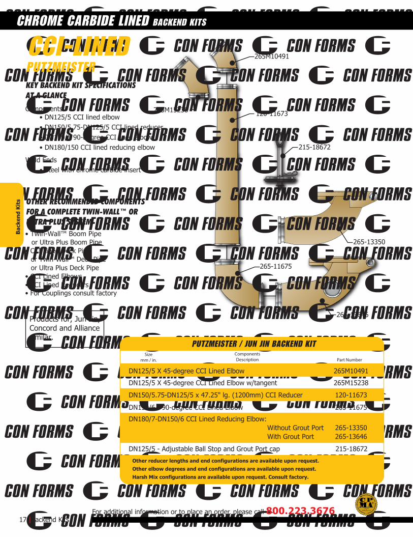
KEY BACKEND KIT SPECIFICATIONSAT A GLANCE
Components:• DN125/5 CCI lined elbow• DN150/5.75-DN125/5 CCI lined reducer• DN150/6 90-degree CCI lined elbow• DN180/150 CCI lined reducing elbow
Weld Ends• Steel with chrome carbide insert
OTHER RECOMMENDED COMPONENTSFOR A COMPLETE TWIN-WALL™ ORULTRA PLUS SYSTEM• Twin-Wall™ Boom Pipe or Ultra Plus Boom Pipe• CCI Lined Deck Pipe
or Twin-Wall™ Deck Pipe or Ultra Plus Deck Pipe• CCI Lined Elbows• CCI Lined Reducers• For Couplings consult factory
17 |Backend Kits
CHROME CARBIDE LINED BACKEND KITS
For additional information or to place an order, please call 800.223.3676
CCI-LINEDPUTZMEISTER
Sizemm / in.
ComponentsDescription Part Number
DN125/5 - Adjustable Ball Stop and Grout Port cap 215-18672
DN125/5 X 45-degree CCI Lined Elbow 265M10491
DN125/5 X 45-degree CCI Lined Elbow w/tangent 265M15238
120-11673DN150/5.75-DN125/5 x 47.25" lg. (1200mm) CCI Reducer
DN150/6 - 90-degree CCI Lined Elbow 265-11675
DN180/7-DN150/6 CCI Lined Reducing Elbow: Without Grout Port 265-13350With Grout Port 265-13646
Bac
kend
Kit
s
PUTZMEISTER / JUN JIN BACKEND KIT
Other reducer lengths and end configurations are available upon request.Other elbow degrees and end configurations are available upon request.Harsh Mix configurations are available upon request. Consult factory.
Products for, Jun Jin,Concord and Alliancesimilar.
ASME B30.27-2014
CERTIFIEDD

265-11019
204-17407
265-09505
265-17298
120-13684
265-17173
204-18672265M10491
120-11475
265-10549
265-11045265-13351
265-09505
187P15197
CCI (chrome carbide insert) Rock Valve Outlet Liner 187P15197
KEY BACKEND KIT SPECIFICATIONSAT A GLANCEComponents:• DN125/5 ID CCI lined elbow• DN150/5.75-DN125/5 CCI lined reducer• DN150/6 90-degree CCI lined elbow• DN180/150 CCI lined reducing elbow Weld Ends• Steel with chrome carbide insert
OTHER RECOMMENDED COMPONENTSFOR A COMPLETE TWIN-WALL™ ORULTRA PLUS SYSTEM• Twin-Wall™ Boom Pipe or Ultra Plus Boom Pipe• CCI Lined Deck Pipe or Twin-Wall™ Deck Pipe or Ultra Plus Deck Pipe• CCI Lined Elbows• CCI Lined Reducers
Visit us on line at www.conforms.comBackend Kits | 18
CHROME CARBIDE LINED BACKEND KITS
CCI-LINEDSCHWING
Sizemm / in.
ComponentsDescription Part Number
Sizemm / in.
ComponentsDescription Part Number
DN125/5 x 45 degree CCI-Lined Elbow 265M10491
DN150/6 - DN125/5 ID x 63"lg. (1600mm) CCI-Lined Reducer 120-11475
DN150/6 - DN125/5 x 59.06"lg. (1500mm) CCI-Lined Reducer120-13684
DN150/6 - 90-degree CCI-Lined Elbow: long tangent 265-11045short tangent 265-10549no tangent 265-09505
DN180/7-DN150/6 CCI-Lined Reducing Elbow 265-13351
DN180/7 - DN150/6 - CCI-Lined Reducing Elbow w/offset
DN180/7 14-degree CCI-Lined Hopper Elbow 265-11019
265-17298DN150/6 - Break-out Straight section (male to female) ends 265-17173
DN180/7 - Hinge mount plate for 7 to 6 Elbow (127P17298) 204-17407
DN150/6 - Adjustable Ball Stop and Grout Port cap 204-18672
DN150/6 - 90-degree CCI-Lined Elbow: no tangent 265-09505
Bac
kend
Kit
s
SCHWING BACKEND KIT
SCHWING BACKEND KIT
Other reducer lengths and end configurations are available upon request.Other elbow degrees and end configurations are available upon request.Harsh Mix configurations are available upon request. Consult factory.
• For Couplings consult factory
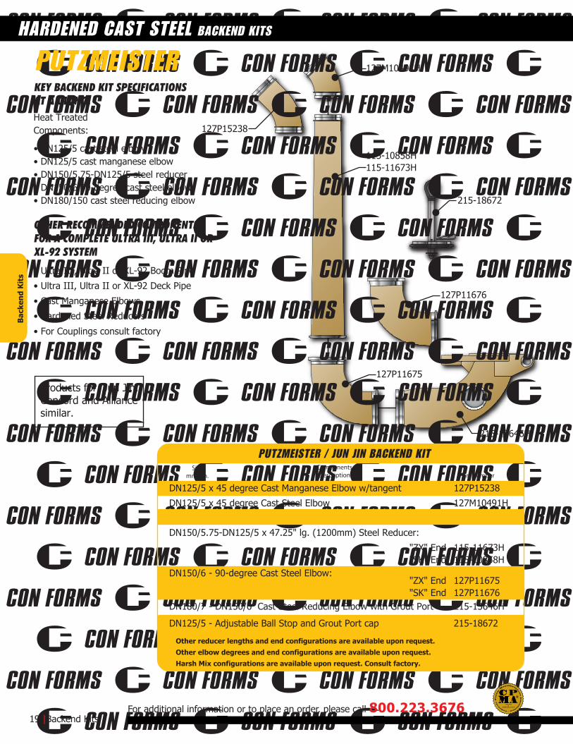
127P15238
127M10491H
115-11673H115-10858H
127P11675
127P11676
215-13646H
215-18672
KEY BACKEND KIT SPECIFICATIONSAT A GLANCEHeat TreatedComponents:
• DN125/5 cast steel elbow• DN125/5 cast manganese elbow• DN150/5.75-DN125/5 steel reducer• DN150/6 90-degree cast steel elbow• DN180/150 cast steel reducing elbow
• Ultra III, Ultra II or XL-92 Boom Pipe
• Ultra III, Ultra II or XL-92 Deck Pipe
• Cast Manganese Elbows
• Hardened Steel Reducers
OTHER RECOMMENDED COMPONENTSFOR A COMPLETE ULTRA III, ULTRA II ORXL-92 SYSTEM
Sizemm / in.
ComponentsDescription Part Number
19 |Backend Kits
HARDENED CAST STEEL BACKEND KITS
For additional information or to place an order, please call 800.223.3676
PUTZMEISTER
DN125/5 x 45 degree Cast Manganese Elbow w/tangent 127P15238
DN125/5 x 45 degree Cast Steel Elbow 127M10491H
DN150/5.75-DN125/5 x 47.25" lg. (1200mm) Steel Reducer:
"ZX" End 115-11673H"SK" End 115-10858H
DN150/6 - 90-degree Cast Steel Elbow:"ZX" End 127P11675"SK" End 127P11676
DN180/7 - DN150/6 Cast Steel Reducing Elbow with Grout Port 215-13646H
DN125/5 - Adjustable Ball Stop and Grout Port cap 215-18672
Bac
kend
Kit
s
PUTZMEISTER / JUN JIN BACKEND KIT
Other reducer lengths and end configurations are available upon request.Other elbow degrees and end configurations are available upon request.Harsh Mix configurations are available upon request. Consult factory.
• For Couplings consult factory
Products for, Jun Jin,Concord and Alliancesimilar.
ASME B30.27-2014
CERTIFIEDD

204-18672
204-17407
127M10491H
115-11475H
204-10549H
204-11019
127P09505
127P17298
127P11677127P02368
204-18035
127P09505
115-13684H
204-17173H
KEY BACKEND KIT SPECIFICATIONSAT A GLANCEHeat treated components:
• DN125/5 cast steel elbow• DN125/5 cast manganese elbow• DN150/125 Induction hardened reducer• DN150/6 90-degree cast steel elbow• DN180/150 cast steel reducing elbow
• Ultra III, Ultra II or XL-92 Boom Pipe
• Ultra III, Ultra II or XL-92 Deck Pipe
• Cast Manganese Elbows
• Hardened Steel Reducers
OTHER RECOMMENDED COMPONENTSFOR A COMPLETE ULTRA III, ULTRA II ORXL-92 SYSTEM
Visit us on line at www.conforms.comBackend Kits | 20
HARDENED CAST STEEL BACKEND KITS
Sizemm / in.
ComponentsDescription Part Number
Sizemm / in.
ComponentsDescription Part Number
DN125/5 x 45 degree Cast Steel Elbow 127M10491H
DN150/6 - DN125/5 x 63"lg. (1600mm) Steel Reducer 115-11475H
DN150/6 - DN125/5 x 59.06"lg. (1500mm) Steel Reducer 115-13684H
DN150/6 - 90-degree Cast Steel Elbow: long tangent 127P11677short tangent 204-10549Hno tangent 127P09505
DN180/7-DN150/6 Cast Steel Reducing Elbow 127P02368
DN180/7 - DN150/6 - Cast Steel Reducing Elbow w/offset
DN180/7 14-degree Hopper Elbow 204-11019
127P17298DN150/6 - Break-out Straight section (male to female) ends 204-17173H
DN180/7 - Hinge mount plate for 7 to 6 Elbow (127P17298) 204-17407
DN150/6 - Adjustable Ball Stop and Grout Port cap 204-18672
DN150/6 - 90-degree Cast Steel Elbow: no tangent 127P09505
Bac
kend
Kit
s
SCHWING
SCHWING BACKEND KIT
SCHWING BACKEND KIT
Other reducer lengths and end configurations are available upon request.Other elbow degrees and end configurations are available upon request.Harsh Mix configurations are available upon request. Consult factory.
• For Couplings consult factory
SOLID LINK
ADJUSTABLE LINKHevi-Duty™ Shown
ADJUSTABLE LINK148mm Shown
Shipping Weight(lbs. / Kg.) Part NumberEnd TypeSize
Shipping Weight(lbs. / Kg.) Part NumberEnd TypeSize
Shipping Weight(lbs. / Kg.) Part NumberEnd TypeSize
Solid Link, Limited Adjustment and Adjustable Couplings for Quick Release Applications
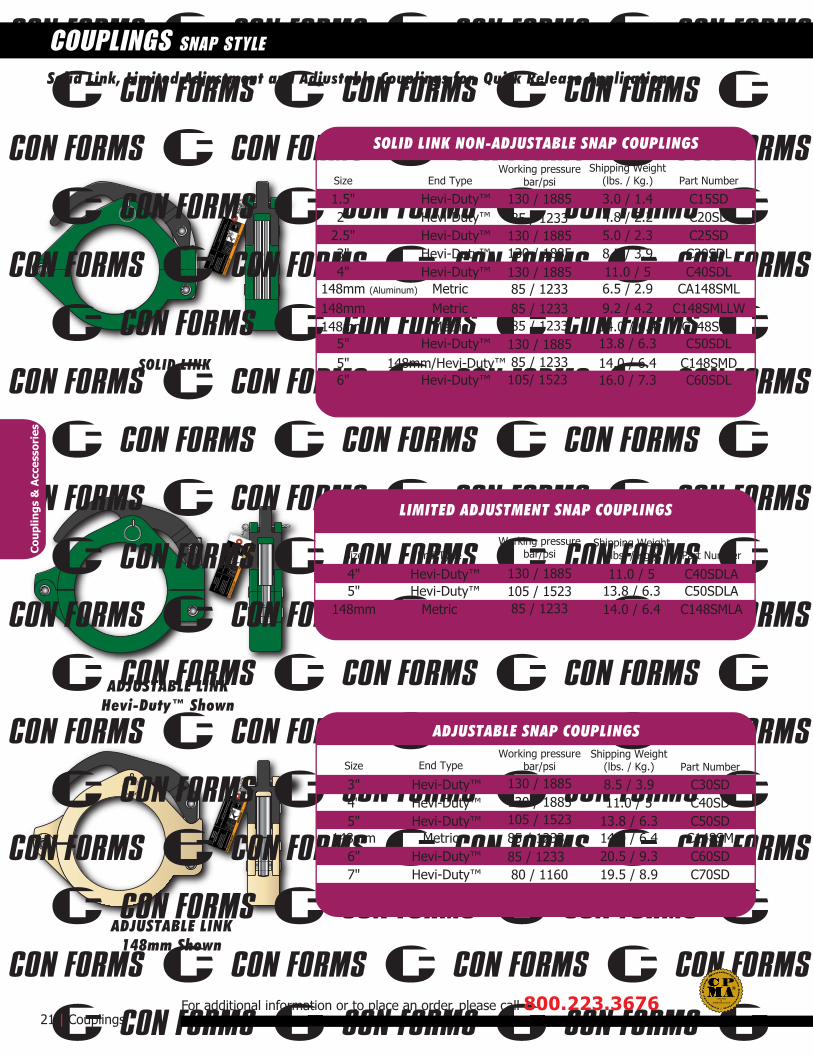
4" Hevi-Duty™ 11.0 / 5 C40SDLA5" Hevi-Duty™ 13.8 / 6.3 C50SDLA
148mm Metric 14.0 / 6.4 C148SMLA
3" Hevi-Duty™ 8.5 / 3.9 C30SD4" Hevi-Duty™ 11.0 / 5 C40SD5" Hevi-Duty™ 13.8 / 6.3 C50SD
148mm Metric 14.0 / 6.4 C148SM6" Hevi-Duty™ 20.5 / 9.3 C60SD7" Hevi-Duty™ 19.5 / 8.9 C70SD
21 | Couplings
COUPLINGS SNAP STYLE
For additional information or to place an order, please call 800.223.3676
1.5" Hevi-Duty™ 3.0 / 1.4130 / 1885
130 / 1885130 / 1885105 / 152385 / 123385 / 123380 / 1160
85 / 1233105 / 1523130 / 1885
105/ 152385 / 1233130 / 188585 / 123385 / 123385 / 1233130 / 1885130 / 1885130 / 188585 / 1233
C15SD2" Hevi-Duty™ 4.8 / 2.2 C20SD
2.5" Hevi-Duty™ 5.0 / 2.3 C25SD3" Hevi-Duty™ 8.5 / 3.9 C30SDL4" Hevi-Duty™ 11.0 / 5 C40SDL
148mm (Aluminum) Metric 6.5 / 2.9 CA148SML148mm Metric 9.2 / 4.2 C148SMLLW148mm Metric 14.0 / 6.4 C148SML
5" Hevi-Duty™ 13.8 / 6.3 C50SDL5" 148mm/Hevi-Duty™ 14.0 / 6.4 C148SMD6" Hevi-Duty™ 16.0 / 7.3 C60SDL
Cou
plin
gs &
Acc
esso
ries
SOLID LINK NON-ADJUSTABLE SNAP COUPLINGS
LIMITED ADJUSTMENT SNAP COUPLINGS
ADJUSTABLE SNAP COUPLINGSWorking pressure
bar/psi
Working pressurebar/psi
Working pressurebar/psi
ASME B30.27-2014
CERTIFIEDD

MAX WP
4350 PSI300 BAR
19.5 LBS
SUPER HIGH
PRESSURE
ShippingWeight(lbs/Kg.)Size End Type Part Number
Shipping Weight(lbs. / Kg.)
Shipping Weight(lbs. / Kg.)
Shipping Weight(lbs. / Kg.)
Part Number
Part Number
Part Number
Part Number
CouplingType
End Type
Description
End Type
End Type
Size
Size
Size
Size
Visit us on line at www.conforms.comCouplings | 22
COUPLINGS TWO-BOLT & SWIVEL STYLE
5" Hevi-Duty™ 19.5 / 8.8 C50BBD-HP6" Hevi-Duty™ 22.5 / 10.2 C60BBD-HP6" Schwing Male/Female 50 / 22.7 C60BBEFI-HP
3" Hevi-Duty™ 7.0 / 3.2 C30BBD4" Hevi-Duty™ 13.0 / 5.9 C40BBD5" Hevi-Duty™ 15.0 / 6.8 C50BBD
148mm Metric 9.75 / 4.4 C148BBM6" Hevi-Duty™ 17.0 / 7.7 C60BBD
5" .600" Hevi-Duty™ Socket Head 2-Bolt C50SSD148mm Metric Socket Head 2-Bolt C148BBM-GF
5" .600" Hevi-Duty™ Hex Head 4-Bolt 200-10501148mm Metric Hex Head 4-Bolt 550-10667
4" .500" Swivel 14.0 / 6.4 SW40
4" .600" Hevi-Duty™ 14.0 / 6.4 DSW405" .500" Swivel 16.0 / 7.3 SW505" .600" Hevi-Duty™ 16.0 / 7.3 DSW50
148mm Metric 13.5 / 6.1 CSW148BM6" .500" Swivel 17.4 / 7.9 SW60
6" .600" Hevi-Duty™ 17.4 / 7.9 DSW60
4"5"6"
.6 /.3 .8 /.41.0 /.5
410-17271410P04645410P04979
Thrust Steel WasherThrust Steel WasherThrust Steel Washer
Cou
plin
gs &
Acc
esso
ries
TWO-BOLT SUPER HIGH PRESSURE COUPLINGCouplings have a working pressure of 300 bar (4351psi)
Couplings assembled with grade 8 bolts
STANDARD TWO-BOLT COUPLINGS
RESTRICTED ACCESS SWIVEL COUPLINGS
THRUST WASHERS
SWIVEL COUPLINGS
Working pressurebar/psi
Working pressurebar/psi
Working pressurebar/psi
300 / 4351
300 / 4351300 / 4351
130 / 1885
130 / 188585 / 1233
130 / 1885130 / 1885
130 / 1885
85 / 1233
130 / 1885130 / 1885
130 / 1885
130 / 1885130 / 1885
85 / 1233130 / 1885
85 / 1233130 / 1885
Working pressurebar/psi

METRIC
METRIC / HEVI-DUTY™
HEVI-DUTY™
CAVITY
SWIVEL GASKETw/STEEL RING
Style Part NumberSize
Style Part NumberSize
GASKETS
GASKETS, BOX QUANTITIESStyle Part NumberSize Units per Box
23 | Coupling Gaskets
COUPLING GASKETS
For additional information or to place an order, please call 800.223.3676
1.5 Hevi-Duty 100 CG15D-BX
2.0 Hevi-Duty 100 CG20D-BX2.5 Hevi-Duty 100 CG25D-BX
3.0 Hevi-Duty 100 CG30D-BX4.0 Hevi-Duty 100 CG40D-BX
5.0 Hevi-Duty 100 CG50D-BX
6.0 Hevi-Duty 50 CG60D-BX148mm Metric 50 CG148M-BX148mm Metric Cavity 50
50
CVG148M-BX
148mm Metric Swivel Lubed 529P09346X-BX
1.5 Flared CG15J1.5 Hevi-Duty CG15D
2.0 Flared CG20J2.0 Hevi-Duty CG20D
2.5 Hevi-Duty CG25D
3.0 Hevi-Duty CG30D
4.0 Hevi-Duty CG40D4.0 Swivel with Steel Ring SWG404.0 Hevi-Duty Swivel Hard Plastic CSWG40D
5.0 Hevi-Duty CG50D5.0 Hevi-Duty Cavity CVG50D5.0 Hevi-Duty Lubed with Tee Lip 529P09787L
DN125/5 Putzmeister ZX style O-Ring 215P16430DN150/6 Putzmeister ZX style O-Ring 215P17865
5.0 Swivel with Steel Ring SWG505.0 Hevi-Duty Swivel Hard Plastic CSWG50D
6.0 Hevi-Duty CG60D6.0 Swivel with Steel Ring SWG606.0 Hevi-Duty Swivel Hard Plastic CSWG60D7.0 Hevi-Duty CG70D
8.0 Hevi-Duty CG80DX148mm Metric CG148M
148mm Metric Cavity CVG148M148mm Metric to Hevi-Duty CG148MD
148mm Metric Swivel Lubed 529P09346X
Cou
plin
gs &
Acc
esso
ries
DN125/5 Schwing Male/Female style D-Ring CG50EFDN150/6 Schwing Male/Female style D-Ring CG60EF
Schwing & Putzmeister GASKETS
ASME B30.27-2014
CERTIFIEDD

Size(in./mm) End Type
End Type
End Type
End Type
End Type
End Type
Kit Part Number
Kit Part Number
Kit Part Number
Kit Part Number
Kit Part Number
Kit Part Number
Contents of Kit
Contents of Kit
Contents of Kit
Contents of Kit
Contents of Kit
Contents of Kit
3/76 Hevi-Duty™ CB30BBD (1) Bolt, (1) Nut
4/102 Hevi-Duty™ CB40BBD (1) 040P04139 Bolt, (1) 040P07870 Nut5/125 Hevi-Duty™ CB50BBD (1) 040P04139 Bolt, (1) 040P07870 Nut5/125 Hevi-Duty™ CB50BBD-HP6/152 Hevi-Duty™ CB60BBD (1) 040P04139 Bolt, (1) 040P07870 Nut6/152 Hevi-Duty™ CB60BBD-HP (1) 040P17549 Bolt, (1) 040P17550 Nut (1) 040P17647 Washer
(1) 040P17549 Bolt, (1) 040P17550 Nut (1) 040P17647 Washer
1.5/38 Hevi-Duty™ CH15SD (1) 403P10603 Handle, (1) 040P04738 Pin2/51 Hevi-Duty™ CH20SD (1) 403P01503 Handle, (1) 040P04665 Pin
2.5/63.5 Hevi-Duty™ CH25SD (1) 403P01503 Handle, (1) 040P04739 Pin3/76 Hevi-Duty™ CH30SD (1) 403P05596 Handle, (1) 040P04662 Pin4/102 Hevi-Duty™ CH40SD (1) 403P01506 Handle, (1) 040P06322 Pin5/125 Hevi-Duty™ CH50SD (1) 403P01508 Handle, (1) 040P06322 Pin
148mm Metric CH148SM (1) 403P01507 Handle, (1) 040P04663 Pin6/152 Hevi-Duty™ CH60SD (1) 403P01508 Handle, (1) 040P04663 Pin7/180 Hevi-Duty™ CH70SD (1) 403P01509 Handle, (1) 040P06975 Pin
1.5/38 All HAIRPIN (1) Hairpin Clip, (1) Warning Label
2/51 All HAIRPIN (1) Hairpin Clip, (1) Warning Label
2.5/63.5 All HAIRPIN (1) Hairpin Clip, (1) Warning Label
3/76 All SAFETYPINS (short)
SAFETYPINL (long)(1) Clinch Pin, (1) Key Ring, (1) Warning Label
4/102 All (1) Clinch Pin, (1) Key Ring, (1) Warning Label5/125 All SAFETYPINL
SAFETYPINLSAFETYPINL
(1) Clinch Pin, (1) Key Ring, (1) Warning Label6/152 All (1) Clinch Pin, (1) Key Ring, (1) Warning Label7/180 All (1) Clinch Pin, (1) Key Ring, (1) Warning Label
1.5/38 Hevi-Duty™ CB15SD (2) 500P01519 Links, (1) 040P04738 Pin2/51 Hevi-Duty™ CB20SD (2) 500P01518 Links, (1) 040P04739 Pin
2.5/63.5 Hevi-Duty™ CB25SD (2) 500P01518 Links, (2) 040P04739 Pin3/76 Hevi-Duty™ CB30SDL (2) 401-11176 Links, (2) 500-11112 Spacers, (2) 040P04662 Pins
4/102 Hevi-Duty™ CB40SDL (2) 500-11184 Links, (2) 040P06322 Pins5/125 Hevi-Duty™ CB50SDL (2) 500-11177 Links, (2) 040P06322 Pins
148mm Metric CB148SML (2) 500-11177 Links, (2) 040P06322 Pins6/152 Hevi-Duty™ CB60SDL (2) 500-11196 Links, (2) 040P07819 Pins
4/102 Hevi-Duty™ CB40SDLA (1) 500-10193 Bolt & Nut, (2) 040P06322 Pins5/125 Hevi-Duty™ CB50SDLA (1) 500-09502 Bolt & Nut, (2) 040P06322 Pins
148mm Metric CB148SMLA (1) 500-09502 Bolt & Nut, (2) 040P06322 Pins
3/76 Hevi-Duty™ CB30SD (1) 401P01516 Nut, (1) 400P08314 Bolt, (2) 040P04662 Pins
4/102 Hevi-Duty™ CB40SD (1) 401P05138 Nut, (1) 400P01511 Bolt, (2) 040P06322 Pins
148mm Metric CB148SM (1) 401P05138 Nut, (1) 400P01512 Bolt, (2) 040P06322 Pins
5/125 Hevi-Duty™ CB50SD (1) 401P05138 Nut, (1) 400P01512 Bolt, (2) 040P06322 Pins6/152 Hevi-Duty™ CB60SD (1) 401P05138 Nut, (1) 400P01512 Bolt, (2) 040P07819 Pins7/180 Hevi-Duty™™ CB70SD (1) 401P01515 Nut, (1) 400P01512 Bolt, (2) 040P04663 Pins
Size(in./mm)
Size(in./mm)
Size(in./mm)
Size(in./mm)
Size I.D.(in./mm)
Visit us on line at www.conforms.comCouplings | 24
COUPLING REPLACEMENT PARTS & KITS
Cou
plin
gs &
Acc
esso
ries
COUPLING HARDWARE REPAIR KITS - TWO-BOLT COUPLINGS
REPLACEMENT HANDLE KITS - SNAP COUPLINGS (ALL TYPES)
COUPLING HARDWARE REPAIR KITS - SOLID LINK NON-ADJUSTABLE SNAP COUPLINGS
REPLACEMENT SNAP HANDLE SAFETY PINS - SNAP COUPLINGS (ALL TYPES)
COUPLING HARDWARE REPAIR KITS - LIMITED ADJUSTMENT SNAP COUPLINGS
COUPLING HARDWARE REPAIR KITS - ADJUSTMENT SNAP COUPLINGS
3/76 TO 6/152 N1
1.25/32 TO 2.5/63.5 N1
2 Layers of wovenwire reinforcement
Extrudedrubber tube
KEY PRODUCT FEATURES
4 Layers of wovenwire reinforcement
Extrudedrubber tube
2 Layers of wovencable reinforcement
Extrudedrubber tube
4 Layers of wovenwire reinforcement
Mfg. Min. Burst(bar / psi)
WorkingPressure(bar / psi) Part Number
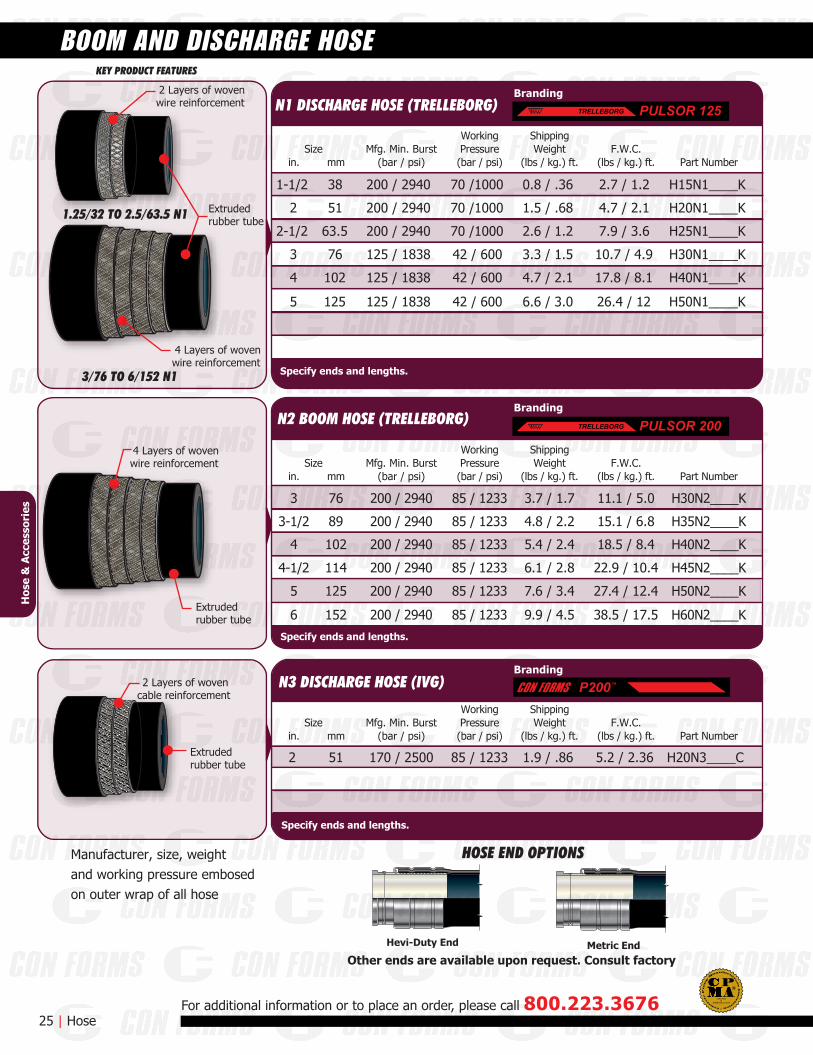
1-1/2 200 / 2940 70 /1000 0.8 / .36 2.7 / 1.2 H15N1____K
2 200 / 2940 70 /1000 1.5 / .68 4.7 / 2.1 H20N1____K
2-1/2 200 / 2940 70 /1000 2.6 / 1.2 7.9 / 3.6 H25N1____K
3 125 / 1838 42 / 600 3.3 / 1.5 10.7 / 4.9 H30N1____K
4 125 / 1838 42 / 600 4.7 / 2.1 17.8 / 8.1 H40N1____K
5 125 / 1838 42 / 600 6.6 / 3.0 26.4 / 12 H50N1____K
ShippingWeight
(lbs / kg.) ft.F.W.C.
(lbs / kg.) ft.Size
in. mm
38
51
63.5
76
102
125
Manufacturer, size, weightand working pressure embosedon outer wrap of all hose
Mfg. Min. Burst(bar / psi)
WorkingPressure(bar / psi) Part Number
85 / 1233170 / 25002 1.9 / .86 5.2 / 2.36 H20N3____C
ShippingWeight
(lbs / kg.) ft.F.W.C.
(lbs / kg.) ft.Size
in. mm
51
Mfg. Min. Burst(bar / psi)
WorkingPressure(bar / psi) Part Number
ShippingWeight
(lbs / kg.) ft.F.W.C.
(lbs / kg.) ft.Size
in. mm
114
76
102
125
152
3 200 / 2940 85 / 1233 3.7 / 1.7 11.1 / 5.0 H30N2____K
3-1/2 200 / 2940 85 / 1233 4.8 / 2.2 15.1 / 6.8 H35N2____K
4 200 / 2940 85 / 1233 5.4 / 2.4 18.5 / 8.4 H40N2____K
4-1/2 200 / 2940 85 / 1233 6.1 / 2.8 22.9 / 10.4 H45N2____K
5 200 / 2940 85 / 1233 7.6 / 3.4 27.4 / 12.4 H50N2____K
6 200 / 2940 85 / 1233 9.9 / 4.5 38.5 / 17.5 H60N2____K
89
25 | Hose
BOOM AND DISCHARGE HOSE
For additional information or to place an order, please call 800.223.3676
Hos
e &
Acc
esso
ries
Specify ends and lengths.
N1 DISCHARGE HOSE (TRELLEBORG)
N3 DISCHARGE HOSE (IVG)
Specify ends and lengths.
N2 BOOM HOSE (TRELLEBORG)
Specify ends and lengths.
P200™
Branding
Branding
Branding
PULSOR 200TRELLEBORGT
PULSOR 125TRELLEBORGT
Other ends are available upon request. Consult factory
HOSE END OPTIONS
Hevi-Duty End Metric End
ASME B30.27-2014
CERTIFIEDD
KEY PRODUCT FEATURES
6 Layers of wovenfiber reinforcement
4 Layers of wovenfiber reinforcement
Extrudedrubber tube
Extrudedrubber tube
3/76 TO 5/125
1/25 TO 2.5/63.5
6 Layers of wovenfiber reinforcement
4 Layers of wovenfiber reinforcement
Extrudedrubber tube
Extrudedrubber tube
3/76 TO 5/125
1.25/32 TO 2.5/63.5
Plaster & Grout Discharge4 Layers of high
strength synthetic cord40 Bar workingpressure 3:1 SF
Mfg. Min. Burst(bar / psi)
WorkingPressure(bar / psi) Part Number
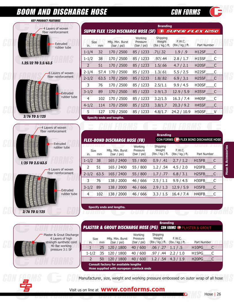
1-1/2 165 / 2400 55 / 800 0.9 / .41 2.7 / 1.2 H15FB____C
2 165 / 2400 55 / 800 1.2 / .54 4.5 / 2.0 H20FB____C
2-1/2 165 / 2400 55 / 800 1.7 / .77 6.8 / 3.1 H25FB____C
3 138 / 2000 46 / 666 2.5 / 1.1 9.9 / 4.5 H30FB____C
3-1/2 138 / 2000 46 / 666 2.9 / 1.3 12.9 / 5.9 H35FB____C
4 138 / 2000 46 / 666 3.3 / 1.5 16.4 / 7.4 H40FB____C
ShippingWeight
(lbs / kg.) ft.F.W.C.
(lbs / kg.) ft.Size
in. mm
38
51
63.5
76
89
102
Mfg. Min. Burst(bar / psi)
WorkingPressure(bar / psi) Part Number
1-1/4 85 / 1233
85 / 1233
85 / 1233
85 / 1233
85 / 1233
85 / 1233
85 / 1233
85 / 1233
85 / 1233
170 / 2500
170 / 2500
170 / 2500
170 / 2500
170 / 2500
170 / 2500
170 / 2500
170 / 2500
170 / 2500
.71/.32 1.9 / .9 H12SF____C
1-1/2 .97/.44 2.8 / 1.7 H15SF____C
2 1.5/.66 4.7 / 2.1 H20SF____C
2-1/2 1.8/.82 6.9 / 3.1 H25SF____C
3 2.5/1.1 9.9 / 4.5 H30SF____C
3-1/2 2.9/1.3 12.9 / 5.9 H35SF____C
4 3.2/1.5 16.3 / 7.4 H40SF____C
4-1/2 3.8/1.7 20.3 / 9.2 H45SF____C
5 4.8/1.7 24.2 / 10.9 H50SF____V
ShippingWeight
(lbs / kg.) ft.F.W.C.
(lbs / kg.) ft.Size
in. mm
32
38
51
63.5
85 / 1233170 / 25002-1/4 1.3/.61 5.5 / 2.5 H22SF____C57.4
76
89
102
114
127
Manufacturer, size, weight and working pressure embossed on outer wrap of all hose
Visit us on line at www.conforms.com Hose | 26
BOOM AND DISCHARGE HOSE
BrandingCON FORMS FLEX BOND DISCHARGE HOSE
Hos
e &
Acc
esso
ries
FLEX-BOND DISCHARGE HOSE (FB)
Specify ends and lengths.
Mfg. Min. Burst(bar / psi)
WorkingPressure(bar / psi) Part Number
ShippingWeight
(lbs / kg.) ft.F.W.C.
(lbs / kg.) ft.Size
in. mm
Branding
Hose supplied with european camlock endsConsult factory for available lengths
SUPER FLEX 1250 DISCHARGE HOSE (SF)
Specify ends and lengths.
Branding
PLASTER & GROUT DISCHARGE HOSE (PG) PLASTER & GROUT
1-1/2 120 / 1800 40 / 600 .97 / .44 2.2 / 1.0 H15PG____C352 120 / 1800 40 / 600 1.2 / .54 4.3 / 1.9 H20PG____C50
1 120 / 1800 40 / 600 .06 / .27 1.1 / .5 H10PG____C25
HOSE END OPTIONS
Manufacturer, size, weightand working pressure embosed
on outer wrap of all hose
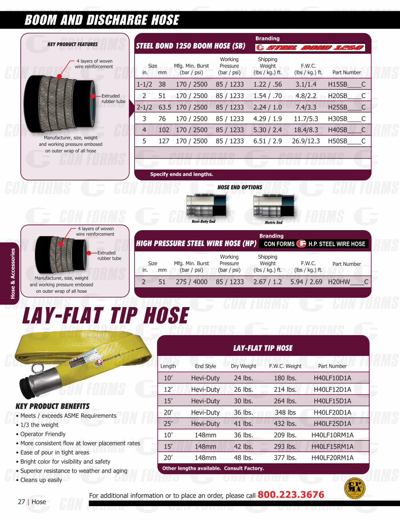
4 layers of wovenwire reinforcement
Extrudedrubber tube
Extrudedrubber tube
4 layers of wovenwire reinforcement
KEY PRODUCT FEATURES STEEL BOND 1250 BOOM HOSE (SB)
Mfg. Min. Burst(bar / psi)
WorkingPressure(bar / psi) Part Number
85 / 1233
85 / 1233
85 / 1233
85 / 1233
85 / 1233
85 / 1233170 / 2500
170 / 2500
170 / 2500
170 / 2500
170 / 2500
170 / 2500
1-1/2 1.22 / .56 3.1/1.4 H15SB____C
2 1.54 / .70 4.8/2.2 H20SB____C
2-1/2 2.24 / 1.0 7.4/3.3 H25SB____C
3 4.29 / 1.9 11.7/5.3 H30SB____C
4 5.30 / 2.4 18.4/8.3 H40SB____C
5 6.51 / 2.9 26.9/12.3 H50SB____C
Specify ends and lengths.
ShippingWeight
(lbs / kg.) ft.F.W.C.
(lbs / kg.) ft.Size
in. mm
38
51
63.5
76
102
127
Hevi-Duty End Metric End
27 | Hose
BOOM AND DISCHARGE HOSE
For additional information or to place an order, please call 800.223.3676
Branding
HIGH PRESSURE STEEL WIRE HOSE (HP)
Mfg. Min. Burst(bar / psi)
WorkingPressure(bar / psi)
Part Number
85 / 1233275 / 40002 2.67 / 1.2 5.94 / 2.69 H20HW____C
ShippingWeight
(lbs / kg.) ft.F.W.C.
(lbs / kg.) ft.Size
in. mm
51
Branding
Hos
e &
Acc
esso
ries
Manufacturer, size, weightand working pressure embosed
on outer wrap of all hose
LAY-FLAT TIP HOSE
CON FORMS H.P. STEEL WIRE HOSE
KEY PRODUCT BENEFITS• Meets / exceeds ASME Requirements• 1/3 the weight• Operator Friendly• More consistent flow at lower placement rates• Ease of pour in tight areas• Bright color for visibility and safety• Superior resistance to weather and aging• Cleans up easily
LAY-FLAT TIP HOSE
End Style Dry Weight Part Number
42 lbs.
36 lbs.
41 lbs.
36 lbs.
30 lbs.
26 lbs.
24 lbs.Hevi-Duty
Hevi-Duty
Hevi-Duty
Hevi-Duty
Hevi-Duty
148mm
148mm
10’ 180 lbs. H40LF10D1A
12’ 214 lbs. H40LF12D1A
15’ 264 lbs. H40LF15D1A
20’ 348 lbs H40LF20D1A
25’ 432 lbs. H40LF25D1A
10’ 209 lbs. H40LF10RM1A
15’
20’
293 lbs. H40LF15RM1A
F.W.C. WeightLength
48 lbs.148mm 377 lbs. H40LF20RM1A
ASME B30.27-2014
CERTIFIEDD
Other lengths available. Consult Factory.
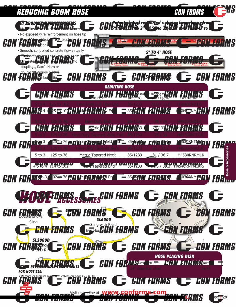
5" TO 4" HOSE
Patented steel reinforced reducing boom hoses from:5” to 4”, 5“ to 3” , 4.5“ to 3”, 4.5” to 4” and 4” to 3”
HOSE ACCESSORIESSL5000
Double Choker Sling SL6000
Sling with Rigid Eye Hook & D-Ring
SL3000DSling Chokerwith D-Ring
SLINGS
OTHER RECOMMENDED COMPONENTSFOR HOSE SEE:
KEY PRODUCT CHARACTERISTICS• Maintains air entrainment within concrete• No exposed wire reinforcement on hose tip• 5" to 3" hose ideal for ICF, block and form filling applications• Smooth, controlled concrete flow virtually eliminates splatter and reduces boom bounce• Eliminates need for steel reducer and couplings, Ram’s Horn or double 90-degree elbows• Less weight at boom tip 5" TO 3" HOSE
Visit us on line at www.conforms.com Hose | 28
REDUCING BOOM HOSE
Hos
e &
Acc
esso
ries
REDUCING HOSE
5 to 4 125 to 102 Hevi-Duty Full Flow End H5040RND1K
5 to 4 Metric Full Flow End H5040RNM1K
5 to 3 85/1233 H4530RND1K
5 to 3 85/1233 H4530RNM1K
5 to 3 85/1233 H4530RNTD1K
5 to 3 85/1233 H4530RNTM1K
5 to 3 85/1233 H4530RNRD1K
5 to 3 85/1233 H4530RNRM1K
End StyleWorking Pressure
(bar / psi) Part NumberShipping Weight
(lbs / kg.) ft.Size
in. mm
85/1233
85/1233 71.8 / 32.6
72.8 / 33.0
4.5 to 4 114 to 102 Metric Tapered End H4540RNTM1K-S85/1233 86.5 / 39.2
125 to 102
125 to 76
125 to 76
125 to 76
125 to 76
125 to 76
125 to 76
Hevi-Duty End
Metric End
Hevi-Duty Tapered Weld End
Metric Tapered Weld End
Hevi-Duty Tapered Neck
Metric Tapered Neck
74 / 33.6
75 / 34
74 / 33.6
75 / 34
81 / 36.7
82 / 37.2
4.0 to 3 102 to 76 Metric Tapered End H4030RNM1K85/1233 80/36
HOSE PLACING DISKDesription Part Number
• Remote or Manual Air Cuff™ Valves on pages 29 & 30
24” diameter steel LH-54

MANUAL KIT
AIR CUFF™VALVE ASSEMBLY
REMOTE KIT
DNWEIGHT FWCWEIGHT NETP/N NOTES
mm WPmax bar psi
DNWEIGHT FWCWEIGHT NETP/N NOTES
mm bar psiWPmax
KEY PRODUCT SPECIFICATIONS AT A GLANCELength: 15"Diameter: 9.5"Weight: 21 lbsMax. Air Pressure: 90 psiCycle Time: 4 seconds
KEY PRODUCT CHARACTERISTICS• Cycle time of 4 seconds, eliminates spill and waste• Fits all 3" through 5" diameterdischarge hose• Eliminates the need to kink andwire hose at the tip• Operates from truck’s air supply• Can be operated by hand held remote control or integrated into pumps control box. • Consult factory for details.• Includes Air Cuff™, remote and fittings for complete installation• Safe alternative to hose kinking
Manual Air Cuff™ Kit V50ASC-MANRemote Control Kits (Universal Kits)
12-Volt Air Cuff™ Kit V50ASC-12R
24-Volt Air Cuff™ Kit V50ASC-24R
AIR CUFF™REPLACEMENT CUFF
29 | Air-Cuff™ Valve
AIR-CUFF™ HOSE SHUT OFF VALVE
For additional information or to place an order, please call 800.223.3676
Product Description
Replacement Cuff
Replacement Remote
V50ASC-ACA
051P13594
Replacement air valve assembly for 12 volt V50ASC-RC12
V50ASC-RC24Replacement air valve assembly for 24 volt
Replacement air solenoid valve for 12 volt 050P14239
Replacement 1/2” air regulator 050P14378
050P14257Replacement air solenoid valve for 24 volt
Part Number
Product Description Part Number
Hos
e &
Acc
esso
ries
AIR CUFF™ SHUT-OFF VALVE
AIR CUFF™ REPLACEMENT PARTS
Other replacement parts available consult factory.
ASME B30.27-2014
CERTIFIEDD
KEY PRODUCT SPECIFICATIONS AT A GLANCELength: Approx. 36” long.Diameter: 9.5"Max. Air Pressure: 100 psiMaximum back pressure: 75 psi
DNWEIGHT FWCWEIGHT NETP/N NOTES
mm WPmax bar psi
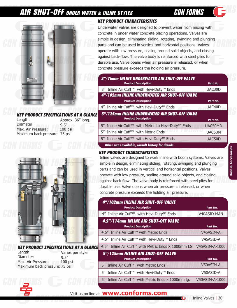
KEY PRODUCT CHARACTERISTICSUnderwater valves are designed to prevent water from mixing withconcrete in under water concrete placing operations. Valves aresimple in design, eliminating sliding, rotating, swinging and plungingparts and can be used in vertical and horizontal positions. Valvesoperate with low pressure, sealing around solid objects, and closingagainst back-flow. The valve body is reinforced with steel plies fordurable use. Valve opens when air pressure is released, or whenconcrete pressure exceeds the holding air pressure.
KEY PRODUCT CHARACTERISTICS
5” Inline Air Cuff™ with Metric Ends
4.5” Inline Air Cuff™ with Metric Ends V45ASIM-A
4” Inline Air Cuff™ with Hevi-Duty™ Ends V40ASID-MAN
5” Inline Air Cuff™ with Hevi-Duty™ Ends V50ASID-A
5” Inline Air Cuff™ with Metric Ends x 1000mm lg.
4.5” Inline Air Cuff™ with Metric Ends X 1000mm LG. V45ASIM-A-1000
4.5” Inline Air Cuff™ with Hevi-Duty™ Ends
UAC50MD
UAC40D
UAC30D
UAC50M
UAC50D
V45ASID-A
V50ASIM-A
V50ASIM-A-1000
Visit us on line at www.conforms.comInline Valves | 30
AIR SHUT-OFF UNDER WATER & INLINE STYLES
5” Inline Air Cuff™ with Metric to Hevi-Duty™ Ends
4” Inline Air Cuff™ with Hevi-Duty™ Ends
3” Inline Air Cuff™ with Hevi-Duty™ Ends
5” Inline Air Cuff™ with Metric Ends
5” Inline Air Cuff™ with Hevi-Duty™ Ends
KEY PRODUCT SPECIFICATIONS AT A GLANCELength: Varies per styleDiameter: 9.5"Max. Air Pressure: 100 psiMaximum back pressure: 75 psi
Hos
e &
Acc
esso
ries
Part No.
Part No.
Part No.
Part No.
Part No.
Part No.
5”/125mm INLINE AIR SHUT-OFF VALVEProduct Description
4.5”/114mm INLINE AIR SHUT-OFF VALVEProduct Description
4”/102mm INLINE AIR SHUT-OFF VALVEProduct Description
5”/125mm INLINE UNDERWATER AIR SHUT-OFF VALVEProduct Description
4”/102mm INLINE UNDERWATER AIR SHUT-OFF VALVEProduct Description
3”/76mm INLINE UNDERWATER AIR SHUT-OFF VALVEProduct Description
Inline valves are designed to work inline with boom systems. Valves aresimple in design, eliminating sliding, rotating, swinging and plungingparts and can be used in vertical and horizontal positions. Valvesoperate with low pressure, sealing around solid objects, and closingagainst back-flow. The valve body is reinforced with steel plies fordurable use. Valve opens when air pressure is released, or whenconcrete pressure exceeds the holding air pressure.
Other sizes available, consult factory for details

CLEANOUT BALLS
GO-DEVILS
BLOWOUT CAPS
DEVIL CATCHERS
WATER BLOWOUTCAP
PUMP PRIMER
PRIME TIME IIa product of
Construction Forms Inc. P.O. Box 308 Port Washington, WI 53074
PRIMETIME
a product of
Net contents 2fl oz. (59ml)PN: PTL
LIQUIDCall: 800•223•3676www.conforms.com
Size Boom Go-Devil Go-Devil Cleanout Cubes Foam Boom BallSpongeCleanout
Ball - Hard
High PerformanceElastomeric compound
Cleanout Ball2.0 - GO-D20 - - COBH20 COBS202.5 - GO-D25 - - COBH25 COBS253.0 -
-GO-D30 - - COBH30 COBS30
4.0 GO-D40 - BB40 COBH40 COBS405.0 BGO-D50 GO-D50 COCM-50 BB50 COBH50 COBP50 COBS506.0 - GO-D60 COCM-60 BB60 COBH60 COBS607.0 - GO-D70 - - - -8.0 - GO-D80 - - - -
Product Contents Part Number
Prime Time II 1 Pail / with 60 - 8oz.bags
Prime Time II
Size Devil Catcher Air Blowout Cap Water Blowout Cap End Cap
3.04.05.06.0
148mm DC50M
Sponge CleanoutBall - Soft
31 |Clean out
CLEAN OUT ACCESSORIES
For additional information or to place an order, please call 800.223.3676
Skid of 36 Pails PTPII-SPrime Time Liquid 1/pack PTLPrime Time Liquid 1 Box / with 60 packs PTL-BX
DC30D BOC30_ADC40D BOC40_ADC50D BOC50_ADC60D BOC60_A
BOC50MA BOC50M
BOC30D EC30D2.5 DC25D ----------- BOC25D EC25D2.0 DC20D ----------- ---------- EC20D
BOC40D EC40DBOC50D EC50DBOC60D
Water Blowout Cap with 3/4 nipple
BOC50M-3/4
BOC30D-3/4BOC25D-3/4BOC20D-3/4
BOC40D-3/4BOC50D-3/4--------------- EC60D
EC148M
Cle
anou
t A
cces
sori
es CONCRETE PUMP PRIMER
DEVIL CATCHERS, BLOW-OUT CAPS, END CAPS
Specify types of ends required.
BALLS, SPONGES, GO-DEVILS
PTPII
ASME B30.27-2014
CERTIFIEDD
Visit us on line at www.conforms.comWear Parts | 32
WEAR PARTS
Wea
r P
arts
Size
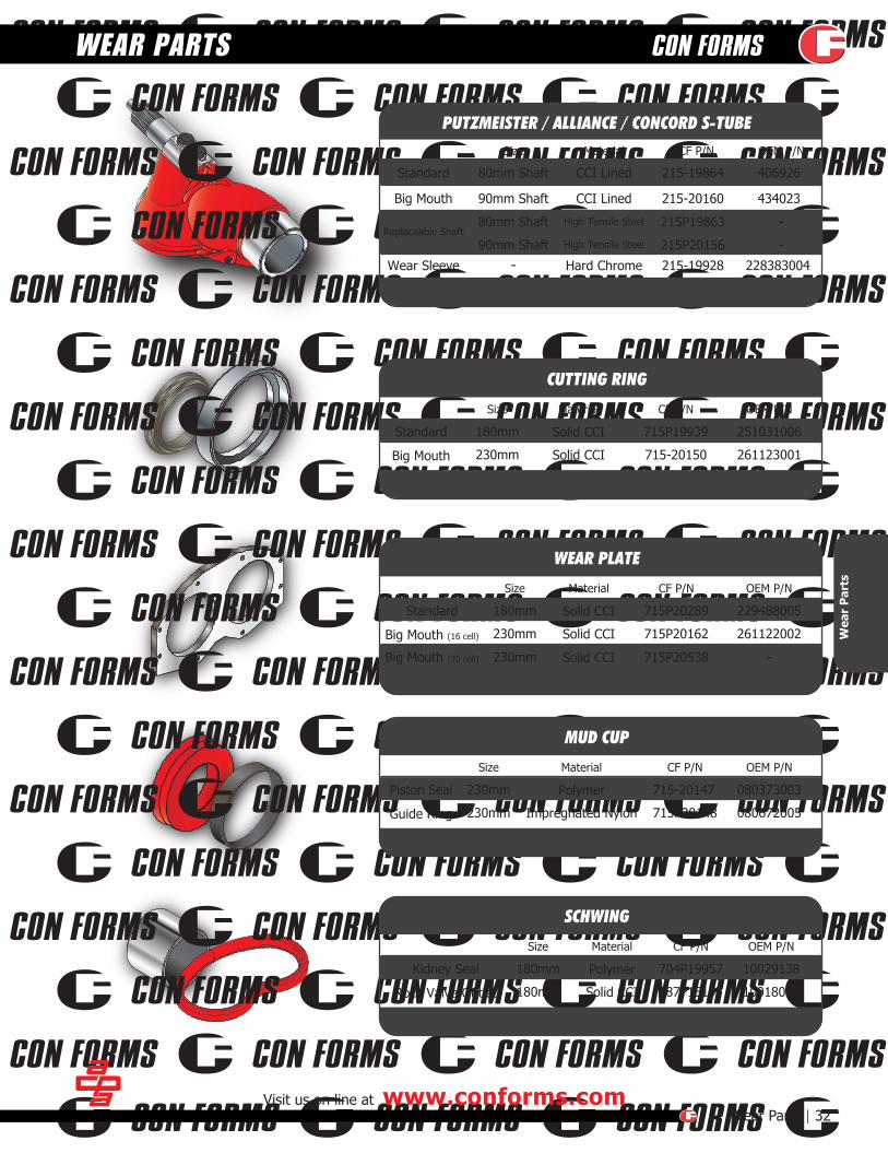
80mm Shaft 215-19864
CF P/N
406926
OEM P/N
CCI LinedStandard
PUTZMEISTER / ALLIANCE / CONCORD S-TUBEMaterial
90mm Shaft 215-20160 434023CCI LinedBig Mouth
80mm Shaft
90mm Shaft
215P19863
215P20156
-
-High Tensile Steel
High Tensile SteelReplaceable Shaft
- 215-19928 228383004Hard ChromeWear Sleeve
180mm
230mm
715P19939
715-20150
251031006
261123001Solid CCI
Solid CCIStandard
Big Mouth
CUTTING RING
Size CF P/N OEM P/NMaterial
180mm
230mm
715P20289
715P20162
229488005
261122002Solid CCI
Solid CCIStandard
Big Mouth (16 cell)
WEAR PLATE
Size CF P/N OEM P/NMaterial
230mm
230mm
715-20147
715P20148
080373003
080672005Impregnated Nylon
PolymerPiston Seal
Guide Ring
MUD CUP
Size CF P/N OEM P/NMaterial
180mm
180mm
704P19957
187P15197
10029138
10018029Solid CCI
PolymerKidney Seal
Rock Valve Outlet
SCHWING
Size CF P/N OEM P/NMaterial
230mm 715P20538 -Solid CCIBig Mouth (20 cell)
HEVI-DUTY™ ENDS
SCHWING MALE / FEMALE
PUTZMEISTERZX MALE / FEMALE
33 | Line PumpingFor additional information or to place an order, please call 800.223.3676
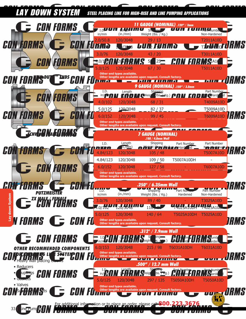
STEEL PLACING LINE FOR HIGH-RISE AND LINE PUMPING APPLICATIONS
2.0/50.8 120/3048 29 / 13 T2011A10D
2.5/63.5 120/3048 32 / 15 T2511A10D
3.0/76 120/3048 43 / 20 T3011A10D
4.0/102 120/3048 55 / 25 T4011A10D
5.0/125 120/3048 67 / 30 T5011A10D
4.0/102 120/3048 68 / 31 T4009A10D
5.0/125 120/3048 82 / 37 T5009A10D
6.0/152 120/3048 99 / 45 T6009A10D
4.84/123 120/3048 105 / 48 -
-
T5007A10D
6.0/152 120/3048 127 / 58 - T6007A10D
4.84/123 120/3048 109 / 50 T5007A10DH -
Part NumberNon-Hardened
3.0/76 120/3048 89 / 40 T3025A10D
4.0/102 120/3048 116 / 53 T4025A10DH T4025A10D
5.0/125 120/3048 140 / 64 T5025A10DH T5025A10D
6.0/153 120/3048 215 / 98 T6031A10DH T6031A10D
5.0/125 120/3048 297 / 135 T5050A10DH T5050A10D
Part NumberHardened
ShippingWeight (lbs. / Kg.)
Part NumberNon-Hardened
Part NumberHardened
ShippingWeight (lbs. / Kg.)
Part NumberNon-Hardened
Part NumberHardened
ShippingWeight (lbs. / Kg.)
Part NumberNon-Hardened
Part NumberHardened
ShippingWeight (lbs. / Kg.)
Part NumberNon-Hardened
ShippingWeight (lbs. / Kg.)
Part NumberNon-Hardened
ShippingWeight (lbs. / Kg.)
Length(in./mm)
I.D.in/mm
I.D.in/mm
I.D.in/mm
I.D.in/mm
I.D.in/mm
I.D.in/mm
OTHER RECOMMENDED COMPONENTSFOR A PLACING LINE SYSTEM• Heavy wall placing elbows• Reducers• Couplings• Gaskets• Valves• Support brackets
LAY DOWN SYSTEMLa
y do
wn
Syst
em
11 GAUGE (NOMINAL) .120” / 3mm
.250" / 6.35mm Wall
.312" / 7.9mm Wall
.500” / 12.7 mm Wall
Other end types available. Other lengths are available upon request. Consult factory.
Other end types available. Other lengths are available upon request. Consult factory.
9 GAUGE (NOMINAL) .150” / 3.8mm
7 GAUGE (NOMINAL) .188 / 4.8mm Wall
Other end types available. Other lengths are available upon request. Consult factory.
Other end types available. Other lengths are available upon request. Consult factory.
Other end types available. Other lengths are available upon request. Consult factory.
Other end types available. Other lengths are available upon request. Consult factory.
Length(in./mm)
Length(in./mm)
Length(in./mm)
Length(in./mm)
Length(in./mm)
ASME B30.27-2014
CERTIFIEDD
SCHWING MALE / FEMALE
PUTZMEISTERZX MALE / FEMALE
Available on 6 to 5 reducersOther end styles availableconsult factory for details
DNWEIGHT FWCWEIGHT NETP/N NOTES
mm WPmax bar psi
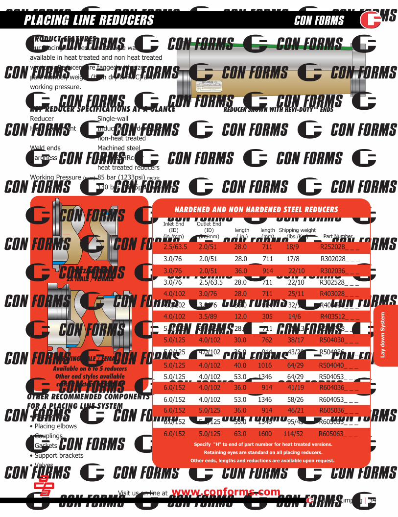
Our Placing Line reducer is single wall,available in heat treated and non heat treatedversions. Reducers are tagged with size, part number, weight (both dry & FWC) and working pressure.
PRODUCT FEATURES
Inlet End(ID)
(in./mm)
Outlet End(ID)
(in./mm)Shipping weight
(lbs./Kg.)length( in.)
length(mm) Part Number
KEY REDUCER SPECIFICATIONS AT A GLANCESingle-wallInduction Hardened ornon-heat treated Machined steelUp to 50HRc forheat treated reducers85 bar (1233psi) metric
130 bar (1885psi) Hevi-Duty™
Visit us on line at www.conforms.comLine Pumping | 34
PLACING LINE REDUCERS
2.5/63.5 2.0/51 28.0 711 18/9 R252028_ _ _
3.0/76 2.0/51 28.0 711 17/8 R302028_ _ _
3.0/76 2.0/51 36.0 914 22/10 R302036_ _ _
3.0/76 2.5/63.5 28.0 711 22/10 R302528_ _ _
4.0/102 3.0/76 28.0 711 25/11 R403028_ _ _
4.0/102 3.0/76 36.0 914 32/15 R403036_ _ _
4.0/102 3.5/89 12.0 305 14/6 R403512_ _ _
5.0/125 3.0/76 28.0 711 28/13 R503028_ _ _
5.0/125 4.0/102 30.0 762 38/17 R504030_ _ _
5.0/125 4.0/102 36.0 914 43/20 R504036_ _ _
5.0/125 4.0/102 40.0 1016 64/29 R504040_ _ _
5.0/125 4.0/102 53.0 1346 64/29 R504053_ _ _
6.0/152 4.0/102 36.0 914 41/19 R604036_ _ _
6.0/152 4.0/102 53.0 1346 58/26 R604053_ _ _
6.0/152 5.0/125 36.0 914 46/21 R605036_ _ _
6.0/152 5.0/125 53.0 1346 95/43 R605053_ _ _
6.0/152 5.0/125 63.0 1600 114/52 R605063_ _ _
Lay
dow
n Sy
stem
ReducerHeat Treatment
Weld ends Hardness
Working Pressure (max):
HARDENED AND NON HARDENED STEEL REDUCERS
Specify "H" to end of part number for heat treated versions.
Retaining eyes are standard on all placing reducers.
Other ends, lengths and reductions are available upon request.
OTHER RECOMMENDED COMPONENTSFOR A PLACING LINE SYSTEM• Placing line• Placing elbows• Couplings• Gaskets• Support brackets• Valves
REDUCER SHOWN WITH HEVI-DUTY™ ENDS
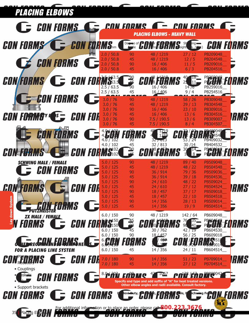
PUTZMEISTERZX MALE / FEMALE
HEVI-DUTY ENDS
SCHWING MALE / FEMALE
DNWEIGHT FWCWEIGHT NETP/N NOTES
mm WPmax bar psi
ShippingWeight (lbs. / Kg.)
IDIn. / mm
Degree ofAngle
Center Line RadiusIn. / mm
2.5 / 63.5 90 48 / 1219 40 / 18 PB259048__2.5 / 63.5 45 48 / 1219 25 / 11 PB254548__2.5 / 63.5 90 16 / 406 14 /6 PB259016__2.5 / 63.5 45 16 / 406 9 / 4 PB254516__
PartNumber
OTHER RECOMMENDED COMPONENTSFOR A PLACING LINE SYSTEM• Placing line• Reducers• Couplings• Gaskets• Valves• Support brackets
35 | Placing Elbows
PLACING ELBOWS
For additional information or to place an order, please call 800.223.3676
2.0 / 50.8 90 48 / 1219 27 / 12 PB209048__2.0 / 50.8 45 48 / 1219 12 / 5 PB204548__2.0 / 50.8 90 16 / 406 11 / 5 PB209016__2.0 / 50.8 45 16 / 406 6 / 3 PB204516__
3.0 / 76 90 48 / 1219 58 / 26 PB309048__3.0 / 76 45 48 / 1219 29 / 13 PB304548__3.0 / 76 90 16 / 406 23 / 10 PB309016__3.0 / 76 45 16 / 406 13 / 6 PB304516__3.0 / 76 90 7.5 / 190.5 13 / 6 PB309007__3.0 / 76 45 7.5 / 190.5 8 / 4 PB304507__
4.0 / 102 90 48 / 1219 72 / 33 PB409048__4.0 / 102 45 48 / 1219 42 /19 PB404548__4.0 / 102 90 32 / 813 53 / 24 PB409032__4.0 / 102 45 32 / 813 30 /14 PB404532__4.0 / 102 90 18 / 457 30 / 14 PB409018__4.0 / 102 45 18 / 457 18 / 8 PB404518__
5.0 / 125 90 48 / 1219 89 / 40 PB509048__5.0 / 125 45 48 / 1219 48 / 22 PB504548__5.0 / 125 90 36 / 914 79 / 36 PB509036__5.0 / 125 45 36 / 914 39 / 18 PB504536__5.0 / 125 90 24 / 610 48 / 22 PB509024__5.0 / 125 45 24 / 610 27 / 12 PB504524__5.0 / 125 90 18 / 457 37 / 17 PB509018__5.0 / 125 45 18 / 457 22 / 10 PB504518__5.0 / 125 90 14 / 356 28 / 13 PB509014__5.0 / 125 45 14 / 356 19 / 9 PB504514__
6.0 / 150 90 48 / 1219 142 / 64 PB609048__6.0 / 150 45 48 / 1219 76 / 35 PB604548__6.0 / 150 90 30 / 762 90 / 41 PB609030__6.0 / 150 45 30 / 762 42 / 19 PB604530__6.0 / 150 90 18 / 457 56 / 25 PB609018__6.0 / 150 45 18 / 457 29 / 13 PB604518__6.0 / 150 90 14 / 356 46 / 21 PB609014__6.0 / 150 45 14 / 356 24 / 11 PB604514__
7.0 / 180 90 14 / 356 51 / 23 PB709014__7.0 / 180 45 14 / 356 27 / 12 PB704514__
8.0 / 203 90 42 / 1067 138 / 63 PB809042__
Lay
dow
n Sy
stem
PLACING ELBOWS - HEAVY WALL
Specify end type and add suffix of "H" for heat treated versions.Other elbow angles and radii available. Consult factory.
D=Hevi-Duty, M= Metric, E= Schwing Male, F= Schwing Female
ASME B30.27-2014
CERTIFIEDD
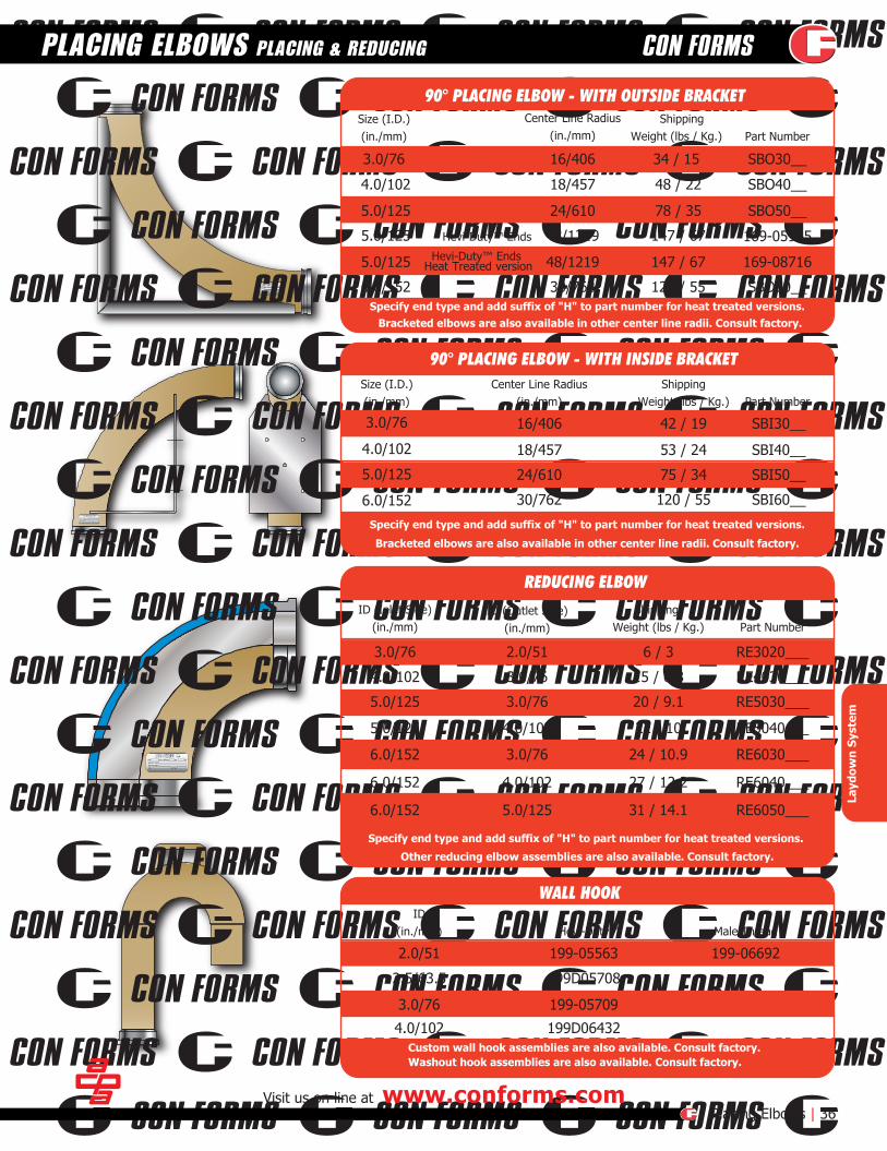
DNWEIGHT FWCWEIGHT NETP/N NOTES
mm WPmax bar psi
DNWEIGHT FWCWEIGHT NETP/N NOTES
mm WPmax bar psi
DNWEIGHT FWCWEIGHT NETP/N NOTES
mm WPmax bar psi
Center Line Radius(in./mm)
ShippingWeight (lbs / Kg.)
Center Line Radius(in./mm)
ShippingWeight (lbs / Kg.)
16/406 42 / 19 SBI30__
18/457 53 / 24 SBI40__
24/610 75 / 34 SBI50__
30/762 120 / 55 SBI60__
ID (Inlet Side)(in./mm)
ID (Outlet Side)(in./mm)
Shipping Weight (lbs / Kg.) Part Number
Part Number
Part Number
ID(in./mm) Hevi-Duty™ Male Thread
Size (I.D.)(in./mm)
3.0/76
4.0/102
5.0/125
6.0/152
Size (I.D.)(in./mm)
Visit us on line at www.conforms.comPlacing Elbows | 36
PLACING ELBOWS PLACING & REDUCING
3.0/76 16/406 34 / 15 SBO30__
Hevi-Duty™ Ends Heat Treated version
4.0/102 18/457 48 / 22 SBO40__
5.0/125 24/610 78 / 35 SBO50__
5.0/125 Hevi-Duty™ Ends 48/1219 147 / 67
5.0/125 48/1219 147 / 67 169-08716
6.0/152 30/762 120 / 55 SBO60__
169-05965
3.0/76 2.0/51 6 / 3 RE3020___
4.0/102 3.0/76 15 / 6.8 RE4030___
5.0/125 3.0/76 20 / 9.1 RE5030___
5.0/125 4.0/102 22 / 10 RE5040___
6.0/152 3.0/76 24 / 10.9 RE6030___
6.0/152 4.0/102 27 / 12.2 RE6040___
6.0/152 5.0/125 31 / 14.1 RE6050___
2.0/51
2.5/63.5
3.0/76
4.0/102
199-05563 199-06692
199D05708
199-05709
199D06432
Layd
own
Syst
em
90° PLACING ELBOW - WITH OUTSIDE BRACKET
REDUCING ELBOW
Specify end type and add suffix of "H" to part number for heat treated versions.Bracketed elbows are also available in other center line radii. Consult factory.
Specify end type and add suffix of "H" to part number for heat treated versions.
Bracketed elbows are also available in other center line radii. Consult factory.
Specify end type and add suffix of "H" to part number for heat treated versions.
Other reducing elbow assemblies are also available. Consult factory.
Custom wall hook assemblies are also available. Consult factory.Washout hook assemblies are also available. Consult factory.
90° PLACING ELBOW - WITH INSIDE BRACKET
WALL HOOK

204-17952H
204-17034H
204-18767H
204-18683H
204-17873H
204-18766H204-17212H
204-17176H 204-18423
Part NumberEnd Style
204-18683H7/180 - 6/152
7/180 - 6/152
7/180 - 6/152
HP Male15.5/394
15.5/394
15.5/394 204-18449HMale
7/180 - 6/152 13.5/343 204-17873H14° Off-set / Male
14° Off-set / Hevi-Duty™7/180 - 6/152 13.7 /347 204-17292H
204-18425HHevi-Duty™
Size(in./mm)
Length(in./mm)
Part NumberEnd Style
204-18766H6/152 5-Bolt / Male High Pressure8.68/220
204-17212H7/180 4-Bolt / Male8.07/205
Size(in./mm)
Length(in./mm)
Part NumberLength End Style
204-18423Hevi-Duty™13/330
204-17176HSchwing Male13/330
Size(in./mm)
Part NumberLength
(in./mm)Turn BuckleHoles-mm End Style
204-17034H6/150-5/125 HP Female63/1600 40.5
End Style
Hevi-Duty™
204-18767H6/150-5/125 HP Female39.4/1000 n/a Female
204-17923H6/150-5/125 HP Female63/1600 57 Hevi-Duty™
Size(in./mm)
Part NumberRadius
(in./mm) End Style
204-18730H6/152 Male / High Pressure Female9/229
204-17952H6/152 High Pressure Male/Female9/229
Size(in./mm)
37 | Line Pumping
LINE PUMPING ADAPTORS BOOM & TRAILER PUMPS
For additional information or to place an order, please call 800.223.3676
204-18596H6/150-5/125 HP Female48/1219 n/a Hevi-Duty™
204-18537H6/150-5/125 HP Female48.81/1240 n/a HP Male
Lay
dow
n Sy
stem
SCHWING 7” to 6” LINE PUMPING ADAPTORWith 4-bolt mount
Other lengths or end styles available. Consult factory
Other lengths or end styles available. Consult factory
SCHWING LINE PUMPING ADAPTORWith 5-bolt or 4-bolt mounts, for use on Schwing trailer pumps
Other end styles available. Consult factory
SCHWING 7” to 6” LINE PUMPING ADAPTORWith pin and wedge mount, for use on Schwing boom trucks
Other lengths or end styles available. Consult factoryReducers available with or without turnbuckle mounts. Consult factory
SCHWING LINE PUMPING REDUCERSWith High Pressure ends, for use on Schwing pumps
Other end styles or bend radius available. Consult factory
SCHWING LINE PUMPING ELBOWSWith High Pressure ends, for use on Schwing boom trucks
7/180 to 6/152
7/180 to 6/152
ASME B30.27-2014
CERTIFIEDD

ZX to Hevi-Duty™ZX Maleto
ZX Female
215-15253With chrome carbide
overlay
215-17074With chrome carbide
liner
215-17176HWith ZX-Female
Part NumberLength
(in./mm)End Style(in./mm)
215-152536/152-5/125 8/203ZX to 5/125 Hevi-Duty™5.6/142.5
215-166966/152 8/203ZX to 6/152 Hevi-Duty™7.1/180
215-185366/152 8/203ZX to 6/152 SK7.8/200
215-170745/125 8/203ZX to 6/152 ZX Female4.5/114
System Size(in./mm)
Part NumberEnd Style
215-17176H7/180 to 6/152
7/180 to 6/152
ZX-Female12.29/312
215D17176HHevi-Duty™12.29/312
Size(in./mm)
Length(in./mm)
Part NumberLength
(in./mm) End Style
116-18854H6/152-5/125 ZX Male47.25/1200
End Style
ZX Female
R6050B812ZXEDH6/152-5/125 ZX Male118.13/3000 Hevi-Duty™
215-19054H6/152-5/125 ZX Male60.25/1530 Hevi-Duty™
R605058PDH6/152-5/125 ZX Male58.0/1473 Hevi-Duty™
Size(in./mm)
Part NumberCLR End Style
PB609009ZEDH6/152 ZX Male to Hevi-Duty™9/229
215-11675H6/152 ZX Male to ZX Female9/229
Size(in./mm)
Visit us on line at www.conforms.comLine Pumping | 38
LINE PUMPING ADAPTORS BOOM & TRAILER PUMPS
R605058PDH
Lay
dow
n Sy
stem
Other end styles available. Consult factory
PUTZMEISTER LINE PUMPING ADAPTORWith ZX end on hopper side, for use on Putzmeister pumps
Other end styles available. Consult factory
PUTZMEISTER 7 to 6 LINE PUMPING ADAPTORWith pin and wedge mount, for use on Putzmeister boom trucks
Other lengths or end styles available. Consult factory
PUTZMEISTER LINE PUMPING REDUCERSWith High Pressure ends, for use on Putzmeister trailer pumps
Other end styles or bend radius available. Consult factory
PUTZMEISTER LINE PUMPING ELBOWSWith High Pressure ends, for use on Putzmeister boom and trailer pumps
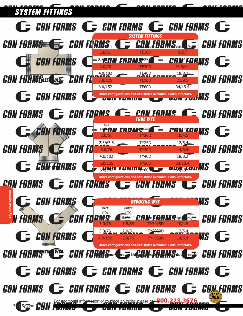
TRUE WYE
TEE ASSEMBLY
REDUCING WYE
39 | System Fittings
SYSTEM FITTINGS
For additional information or to place an order, please call 800.223.3676
Lay
dow
n Sy
stem
Part Number Weight lbs/kgSize
(in./mm)
2.5/63.5 TY25D
3.0/76 TY30D
4.0/102 TY40D
5.0/125 TY50D
6.0/152 TY60D
2.0/51 TY20D
12/5.4
14/6.4
18/8.2
23/10.4
35/15.9
10/4.5
TRUE WYE
Other configurations and end styles available. Consult factory.
Part Number Weight lbs/kg
Inlet(ID)
(in./mm)
3.0/76 TY3020D
4.0/102 TY4030D
3.0/76 TY3015D
12/5.4
14/6.4
10/4.5
REDUCING WYE
Other configurations and end styles available. Consult factory.
Part Number Weight lbs/kgSize
(in./mm)
2.5/63.5 TE25D
TE20D
3.0/76 TE30D
4.0/102 TE40D
5.0/125 TE50D
6.0/152 TE60D
2.0/51
9/4
6/2.7
13.5/6.1
18/8.2
21/9.5
34/15.4
SYSTEM FITTINGS
Other configurations and end styles available. Consult factory.
All part numbers on this page reference hevi-duty™ ends
Outlet(ID)
(in./mm)
2.0/51
3.0/76
1.5/38
ASME B30.27-2014
CERTIFIEDD
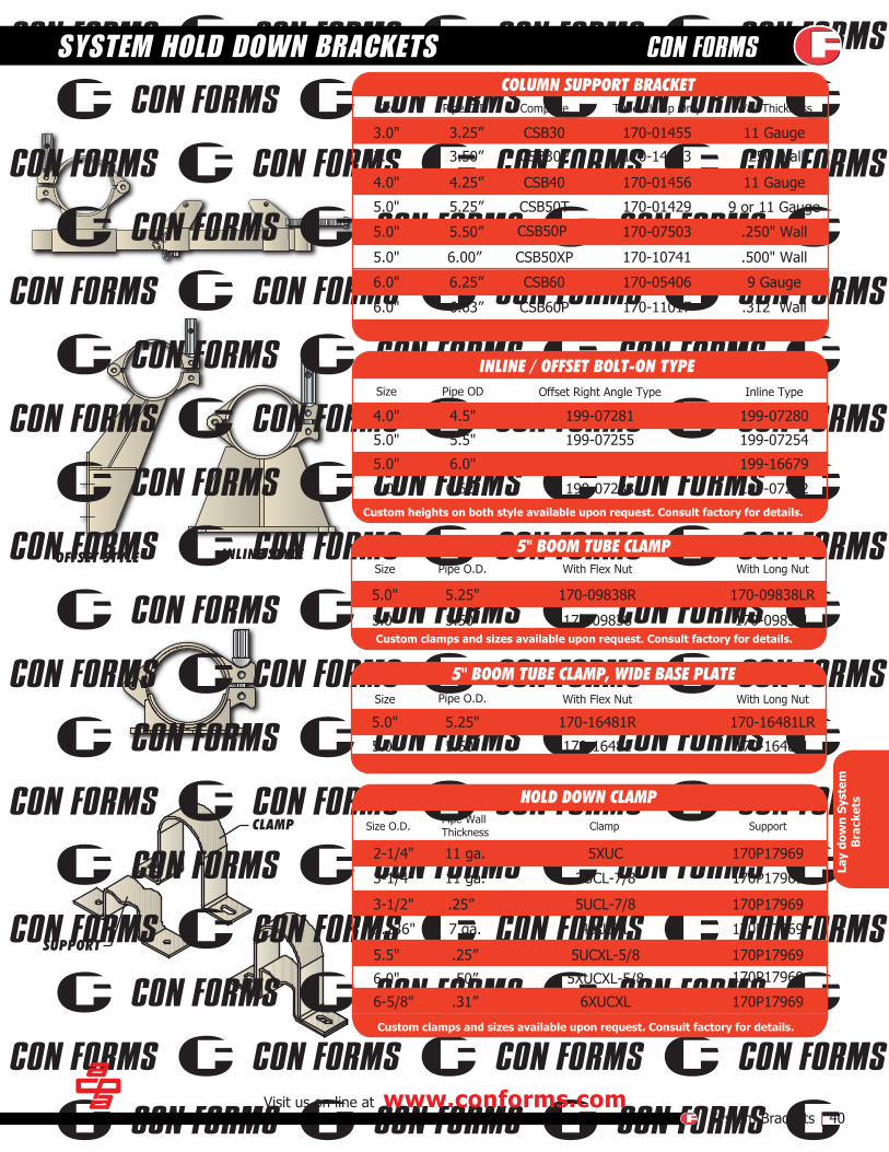
INLINE STYLEOFFSET STYLE
CLAMP
SUPPORT
Visit us on line at www.conforms.comSystem Brackets | 40
SYSTEM HOLD DOWN BRACKETS
Lay
dow
n Sy
stem
Bra
cket
s
Size Pipe O.D. Complete Tube Clamp Only Wall Thickness
Size Offset Right Angle Type Inline Type
4.0" 199-07281 199-07280
5.0" 199-07255 199-07254
6.0"
Pipe OD
4.5"
5.5"
6.62" 199-07283 199-07282
5.0" 6.0" 199-16679
Size Pipe O.D.
5.25" 170-09838R 170-09838LR
5.50" 170-09838 170-09838L
Size With Flex Nut With Long Nut
5.25" 170-16481R 170-16481LR
5.50" 170-16481 170-16481L
Size O.D. Clamp Support
.25”
48UCXL 170P17969
5UCXL-5/8 170P17969
Pipe O.D.
Pipe WallThickness
With Flex Nut With Long Nut
5.0"
5.0"
5.0"
5.0"
.25”5.5"
5.236" 7 ga.
3-1/2" 170P179695UCL-7/8
11 ga.3-1/4" 170P179693UCL-7/8
11 ga.2-1/4" 170P179695XUC
5XUCXL-5/86.0" .50” 170P17969
6XUCXL 170P179696-5/8" .31”
3.25” CSB30 170-01455 11 Gauge
3.0"
4.25” CSB40 170-01456 11 Gauge
9 or 11 Gauge
5.0" CSB50P 170-07503 .250" Wall
6.00” CSB50XP 170-10741
6.0" CSB60 170-05406 9 Gauge
6.0"
5.25” CSB50T5.0" 170-01429
.500" Wall
170-14103 .250 Wall3.50” CSB30P
4.0"
6.63” CSB60P 170-11017 .312 Wall
6.25”
5.0"
5.50”
3.0"
COLUMN SUPPORT BRACKET
INLINE / OFFSET BOLT-ON TYPE
5" BOOM TUBE CLAMP
5" BOOM TUBE CLAMP, WIDE BASE PLATE
HOLD DOWN CLAMP
Custom clamps and sizes available upon request. Consult factory for details.
Custom clamps and sizes available upon request. Consult factory for details.
Custom heights on both style available upon request. Consult factory for details.
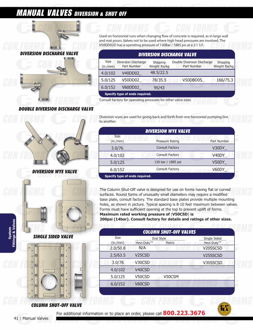
DIVERSION DISCHARGE VALVE
DIVERSION WYE VALVE
DOUBLE DIVERSION DISCHARGE VALVE
COLUMN SHUT-OFF VALVE
SINGLE SIDED VALVE
4.0/102
5.0/125 V50DBD05_
6.0/152
3.0/76 V30DY_
4.0/102 V40DY_
5.0/125 V50DY_
6.0/152 V60DY_
Part NumberPressure Rating
Part Number
V40DD02_
V50DD02_
V60DD02_
Part NumberDouble Diversion DischargeDiversion Discharge
Size(in./mm)
Size(in./mm)
Syst
emFi
ttin
gs &
Val
ves
Specify type of ends required.
DIVERSION DISCHARGE VALVE
Specify type of ends required.
DIVERSION WYE VALVE
41 | Manual ValvesFor additional information or to place an order, please call 800.223.3676
ShippingWeight lbs/kg
78/35.5
48.5/22.5
95/43
ShippingWeight lbs/kg
166/75.3
MANUAL VALVES DIVERSION & SHUT OFF
Used on horizontal runs when changing �ow of concrete is required, as in large walland mat pours. Valves not to be used where high head pressures are involved. The V50DD02D has a operating pressure of 130Bar / 1885 psi at a 2:1 S.F..
Diversion wyes are used for going back and forth from one horizontal pumping lineto another.
Consult factory for operating pressures for other valve sizes.
Hevi-Duty™ Hevi-Duty™End Style
Metric
2.5/63.5
2.0/50.8
V25CSD
N/A
3.0/76 V30CSD
4.0/102 V40CSD
V20SSCSD
V25SSCSD
V30SSCSD
5.0/125 V50CSD V50CSM
6.0/152 V60CSD
Size(in./mm)
Single Sided
COLUMN SHUT-OFF VALVES
The Column Shut-Off valve is designed for use on forms having flat or curvedsurfaces. Round forms of unusually small diameters may require a modifiedbase plate, consult factory. The standard base plates provide multiple mountingholes, as shown in picture. Typical spacing is 8-10 feet maximum between valves. Forms must have sufficient opening at the top to prevent uplift of forms. Maximum rated working pressure of (V50CSD) is 200psi (14bar). Consult factory for details and ratings of other sizes.
130 bar / 1885 psi
Consult Factory
Consult Factory
Consult Factory
ASME B30.27-2014
CERTIFIEDD
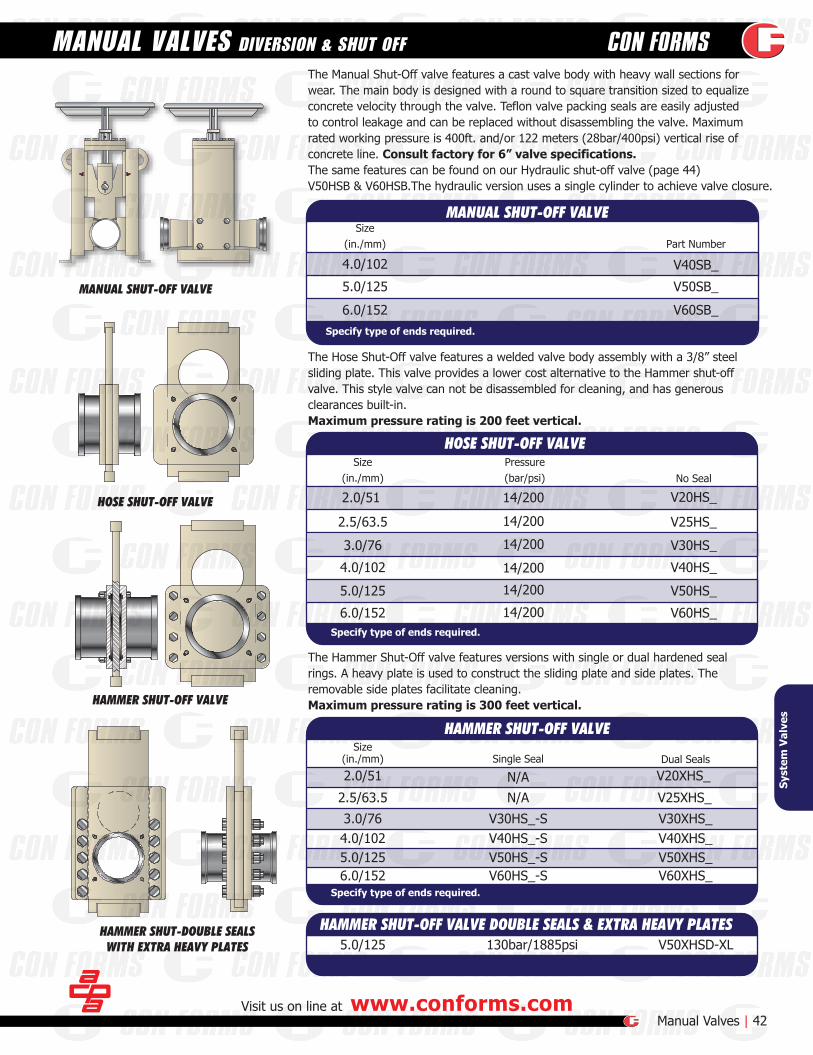
MANUAL SHUT-OFF VALVE
HOSE SHUT-OFF VALVE
HAMMER SHUT-OFF VALVE
HAMMER SHUT-DOUBLE SEALSWITH EXTRA HEAVY PLATES
Visit us on line at www.conforms.comManual Valves | 42
MANUAL VALVES DIVERSION & SHUT OFF
Syst
em V
alve
s
Part Number
V40SB_4.0/102
5.0/125 V50SB_
6.0/152 V60SB_
No Seal
Size(in./mm)
Size(in./mm)
Pressure(bar/psi)
V20HS_
2.5/63.5 V25HS_
3.0/76 V30HS_
4.0/102 V40HS_
5.0/125 V50HS_
6.0/152 V60HS_
14/200
14/200
14/200
14/200
14/200
14/200
2.0/51
Specify type of ends required.
MANUAL SHUT-OFF VALVE
HOSE SHUT-OFF VALVE
Specify type of ends required.
The Manual Shut-Off valve features a cast valve body with heavy wall sections forwear. The main body is designed with a round to square transition sized to equalizeconcrete velocity through the valve. Teflon valve packing seals are easily adjustedto control leakage and can be replaced without disassembling the valve. Maximumrated working pressure is 400ft. and/or 122 meters (28bar/400psi) vertical rise ofconcrete line. Consult factory for 6” valve specifications.The same features can be found on our Hydraulic shut-off valve (page 44)V50HSB & V60HSB.The hydraulic version uses a single cylinder to achieve valve closure.
The Hose Shut-Off valve features a welded valve body assembly with a 3/8” steelsliding plate. This valve provides a lower cost alternative to the Hammer shut-off valve. This style valve can not be disassembled for cleaning, and has generousclearances built-in.Maximum pressure rating is 200 feet vertical.
Dual SealsSingle SealSize
(in./mm)
2.5/63.5 V25XHS_N/AN/A
3.0/76 V30XHS_V30HS_-S4.0/102 V40XHS_V40HS_-S5.0/125 V50XHS_V50HS_-S6.0/152 V60XHS_V60HS_-S
2.0/51 V20XHS_
HAMMER SHUT-OFF VALVE
Specify type of ends required.
The Hammer Shut-Off valve features versions with single or dual hardened sealrings. A heavy plate is used to construct the sliding plate and side plates. Theremovable side plates facilitate cleaning.Maximum pressure rating is 300 feet vertical.
5.0/125 V50XHSD-XL130bar/1885psiHAMMER SHUT-OFF VALVE DOUBLE SEALS & EXTRA HEAVY PLATES

43 | Hydraulic Valves
VALVES HYDRAULIC DIVERSION
For additional information or to place an order, please call 800.223.3676
Part NumberEnd StyleSize
(in./mm)Working pressure
(bar/psi)
5.0/125 V50HYDDD103/1500
103/1500
103/1500
HYDRAULIC DOUBLE DIVERSION VALVE
5.0/125 V50HYDDEF
V50HYDDZX
Hevi-Duty™
Schwing Male / Female
Putzmeister ZX Male/Female5.0/125Other end styles are available upon request. Consult factory.
Part NumberSize
(in./mm)Working pressure
(bar/psi)
5.0/125 V50HYDT103/1500
HYDRAULIC DIVERSION VALVE with 3 OUTLET PORTS
Other end styles are available upon request. Consult factory.
End Style
Hevi-Duty™
Part NumberSize
(in./mm)Working pressure
(bar/psi)
5.0/125 V50HYDDDT103/1500
HYDRAULIC DOUBLE DIVERSION VALVE with 3 OUTLET PORTS
Other end styles are available upon request. Consult factory.
End Style
Hevi-Duty™
Syst
em V
alve
s
The versatile DN125/5 CF Hydraulic Diversion Valve can be set-up to operate in two differentmodes. As a switcher valve, it can be used in set-ups where one concrete pump isfeeding two placement lines. Using this technique, a smooth and quick conversion canbe made from one line to the other to increase the concrete placing capacity and flexibilityof the entire system. As a Shut-Off Valve, the hydraulically powered switcher valve isinstalled in the horizontal placing line at the base of the vertical rise to shut off the line.The line from the pump is connected to one of two inlet ports. The other inlet is then fittedwith a cap or piped to a designated area for concrete disposal. The outlet port is connectedto the placing line system. The concrete filled line can then be hydraulically switched to theside with the cap, thereby holding the vertical head of concrete while the pump is stopped.Valves that use 148mm ends have a maximum pressure rating of 85bar (1233psi).
The versatile DN125/5 CF Hydraulic Double Diversion Valve works as a push pull operation.The push pull is done by two 4” bore 12” stroke hydraulic cylinders. A manually operatedhydraulic directional control valve is mounted on the unit. Two replaceable, hardenedsteel rings provide a seal between the 1-1/2” thick valve plates. Pressure of hydraulic control system cannot exceed 2500psi (172bar).The diversion valve body is rated at a nominal concrete working pressure of 1500psi (103bar) (3:1 SF ) when new. The valve can be operated as a double diversion valve; one inlet,two outlets with a clean out port for each outlet, or a double diversion valve; with one inlet, a priming port and two clean out ports, a stop plug may be installed into the shorter pipe on the double flange assembly to deadhead the line in one position.Valves that use 148mm ends have a maximum pressure rating of 85bar (1233psi).
KEY VALVE CHARACTERISTICS• Versatile & rugged construction• Quick shut-off & easy clean up• Lifting eyes for ease of movement• Mounting brackets for secure anchoring• Hardened wear plates & floating steel sealing rings
Part NumberEnd StyleSize
(in./mm)Working pressure
(bar/psi)
5.0/125 103/1500 V50HYDHevi-Duty™3.0/76 172/2500 V30HYDHevi-Duty™
Hevi-Duty™
Hevi-Duty™
5.0/125 172/2500 V50HYD-HP
V60HYD
HYDRAULIC DIVERSION VALVE
6.0/152
Putzmeister Male/Female V60HYP6.0/152Other end styles are available upon request. Consult factory.
Consult factory.
Consult factory.
See page 52 for howdiversion valve can beoperated
ASME B30.27-2014
CERTIFIEDD
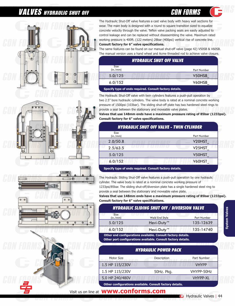
Part NumberMotor Size
Part NumberSize
(in./mm)
5.0/125 V50HSB_
6.0/152 V60HSB_
1.5 HP 115/230V VHYPP
1.5 HP 115/230V VHYPP-50Hz
HYDRAULIC SHUT OFF VALVE - TWIN CYLINDER
Part NumberWeld End StyleSize
(in./mm)
5.0/125
6.0/152 135-14740
HYDRAULIC SLIDING SHUT OFF / DIVERSION VALVE
HYDRAULIC POWER PACK
HYDRAULIC SHUT OFF VALVE
Visit us on line at www.conforms.comHydraulic Valves | 44
VALVES HYDRAULIC SHUT OFF
135-12639Hevi-Duty™
Hevi-Duty™
50Hz. Pkg.
Description
Specify type of ends required. Consult factory details.
Other end configurations available. Consult factory details.Other port configurations available. Consult factory details.
Other configurations available. Consult factory details.
Part NumberSize
(in./mm)
2.5/63.5
5.0/125 V50HST_
V25HST_
2.0/50.8 V20HST_
6.0/152 V60HST_
Specify type of ends required. Consult factory details.
The Hydraulic Shut-Off valve features a cast valve body with heavy wall sections forwear. The main body is designed with a round to square transition sized to equalizeconcrete velocity through the valve. Teflon valve packing seals are easily adjusted tocontrol leakage and can be replaced without disassembling the valve. Maximum ratedworking pressure is 400ft. (122 meters) 28bar (400psi) vertical rise of concrete line.Consult factory for 6” valve specifications.The same features can be found on our manual shut-off valve (page 42) V50SB & V60SB.The manual version uses a hand wheel and Acme threaded rod to achieve valve closure.
The Hydraulic Shut-Off valve with twin cylinders features a push-pull operation bytwo 2.5” bore hydraulic cylinders. The valve body is rated at a nominal concrete workingpressure of 1500psi (103bar). The sliding shut-off plate has two hardened steel rings toprovide a seal between the stationary and moveable valve plates. Valves that use 148mm ends have a maximum pressure rating of 85bar (1233psi).Consult factory for 6” valve specifications.
The Hydraulic Sliding Shut-Off valve features a push-pull operation by one hydrauliccylinder. The valve body is rated at a nominal concrete working pressure of1233psi/85bar. The sliding shut-off/diversion plate has a single hardened steel ring toprovide a seal between the stationary and moveable valve plate.Valves that use 148mm ends have a maximum pressure rating of 85bar (1233psi).Consult factory for 6” valve specifications.
Syst
em V
alve
s
5.0 HP 240/480V VHYPP-XL
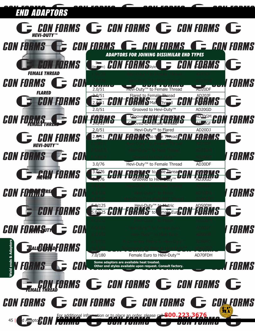
FEMALE THREAD
HEVI-DUTY™
FEMALE THREAD
FLARED
METRIC
HEVI-DUTY™
MALE THREAD
HEVI-DUTY™
MALE THREAD
FEMALE THREAD
Size(in./mm) Style Part Number
1.50/38
1.50/38
Hevi-Duty™ to Female Thread AD15DF
Hevi-Duty™ to Male Thread AD15DM
2.0/51
2.0/51
2.0/51
2.0/51
2.0/51
2.0/51Hevi-Duty™ to Female Thread AD20DF
Flared to Female Thread AD20JF
Flared to Male Thread AD20JM
Grooved to Hevi-Duty™ AD20GD
Grooved to Male Thread AD20GM
2.0/51 Grooved to Female Thread AD20GF
Hevi-Duty™ to Flared AD20DJ
2.0/51 Hevi-Duty™ to Male Thread AD20DM
2.5/63.5 Hevi-Duty™ to Female Thread AD25DF
2.5/63.5
2.5/63.5
Hevi-Duty™ to Male Thread AD25DM
Grooved to Hevi-Duty™ AD25GD
3.0/76 Hevi-Duty™ to Female Thread AD30DF
3.0/76
3.0/76
Hevi-Duty™ to Male Thread AD30DM
Grooved to Hevi-Duty™ AD30GD
4.0/102 Hevi-Duty™ to Female Thread AD40DF
4.0/1024.0/102
Hevi-Duty™ to Metric AD40DMHevi Duty™ to Male NPT Thread AD40DMT
Hevi-Duty™ to Metric AD50DM
Hevi-Duty™ to Female Euro AD50DF
5.0/125
5.0/125
Hevi-Duty™ to Metric AD60DM
Hevi-Duty™ to Female Euro AD60DF
Hevi-Duty™ to Male Euro AD60DE
Putzmeister Metric to Hevi-Duty™ AD60PD
Putzmeister ZX Male to Hevi-Duty™ AD60ZED
Female Euro to Hevi-Duty™ AD70FDH
6.0/152
6.0/152
6.0/152
6.0/152
6.0/152
7.0/180
45 | End Adaptors
END ADAPTORS
For additional information or to place an order, please call 800.223.3676
Wel
d en
ds &
Ada
ptor
s
Some adaptors are available heat treated.Other end styles available upon request. Consult factory.
ADAPTORS FOR JOINING DISSIMILAR END TYPES
ASME B30.27-2014
CERTIFIEDD
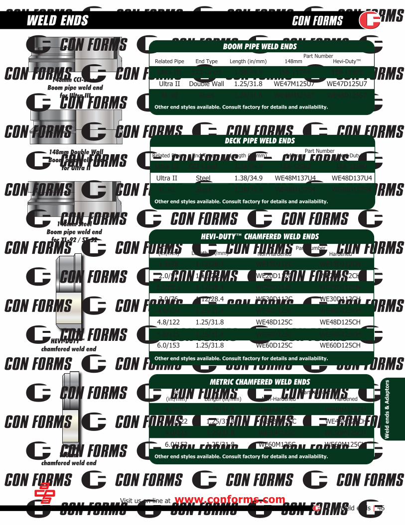
148mm CCI-LinedBoom pipe weld end
for Ultra III
HEVI-DUTY™ chamfered weld end
148mm Double WallBoom pipe weld end
for Ultra II
148mm SteelBoom pipe weld end
for XL-92 / ST-52
148mmchamfered weld end
Part NumberRelated Pipe End Type Length (in/mm) 148mm Hevi-Duty™
Part Number
Ultra III CCI-Lined 1.38/34.9 158-11774 158-11903
Ultra II Double Wall 1.25/31.8 WE47M125U7 WE47D125U7
XL-92 Steel 1.25/31.8 WE48M125S7 WE48D125S7
Part NumberSize(in./mm) Length (in/mm) Non-Hardened Hardened
Part NumberSize(in./mm) Length (in/mm) Non-Hardened Hardened
Visit us on line at www.conforms.comWeld ends | 46
WELD ENDS
Related Pipe End Type Length (in/mm) 148mm Hevi-Duty™
Ultra III CCI-Lined 1.38/34.9 158-12982 158-12990
Ultra II Steel 1.38/34.9 WE48M137U4 WE48D137U4
XL-92 Steel 1.38/34.9 WE48M137S4 WE48D137S4
1.5/38 1.12/28.4 WE15D112C WE15D112CH
2.0/51 1.12/28.4 WE20D112C WE20D112CH
2.5/63.5 1.12/28.4 WE25D112C WE25D112CH
3.0/76 1.12/28.4 WE30D112C WE30D112CH
4.0/102 1.25/31.8 WE40D125C WE40D125CH
4.8/122 1.25/31.8 WE48D125C WE48D125CH
5.0/125 1.25/31.8 WE50D125C WE50D125CH
6.0/153 1.25/31.8 WE60D125C WE60D125CH
4.0/102 1.25/31.8 WE40M125C WE40M125CH
4.8/122 1.25/31.8 WE48M125C WE48M125CH
5.0/125 1.25/31.8 WE50M125C WE50M125CH
6.0/153 1.25/31.8 WE60M125C WE60M125CH
Wel
d en
ds &
Ada
ptor
s
HEVI-DUTY™ CHAMFERED WELD ENDS
METRIC CHAMFERED WELD ENDS
BOOM PIPE WELD ENDS
DECK PIPE WELD ENDS
Other end styles available. Consult factory for details and availability.
Other end styles available. Consult factory for details and availability.
Other end styles available. Consult factory for details and availability.
Other end styles available. Consult factory for details and availability.

PRODUCT DESCRIPTION
Description Part Number
Standard Features• Heavy duty swivel bearing• Double swivel boom for precise concrete placement• Manufactured counterweights• Pin type vertical leg adjustments• 5" Hevi-Duty™ delivery systemOptions• Elevated tower mounts• Aluminum light rail mount• Variety of caster styles• Leg extensionsPower Options• Manual or Remote controlled• 1st stage power (rotational)• 1st and 2nd stage power (rotational)• 1st, 2nd, and 3rd stage power (rotational with elevation jib)
Con Forms Provides "Value Added" Engineering Support Project Layout • Our experienced engineering staff, with years of exposure to a wide variety of projects, are available to assist with project and equipment recommendations.Technology • Our engineers will provide product design information and project support to the customer and their outside vendors. Custom Design and Support • Engineering and field support staff are available to provide product modifications that serve the evolving demands of the project.
The Con Forms Krete Placer is designed to bridge the gapbetween the expense of a placing boom and the manual labor of dragging hose. Standard units are available with boom reach radii of 32', 40', 60' and 70'. The design of the CF Krete Placer provides easy portability to and from the job and requires minimum labor for installation. Features include 360 degree articulating two-stage boomproviding maximum maneuverability for the precise placement of concrete. The features of the CF Krete Placer, are further enhanced through a variety of accessories including casters, rail systems and hydraulic powered radio remote controlled boom options. Con Forms Krete Placers are customizable units, ideal for placing concrete on decks and high-rise projects.Custom placers are available upon request.Please consult factory.
FEATURES
THE COMPLETE PACKAGE
KWIK-COUPLER™
47 | PlacersFor additional information or to place an order, please call 800.223.3676
KRETE PLACERS MANUAL & HYDRAULIC
See page 48 for details
32' Deck Placer DP5032
40' Deck Placer DP5040
40' Deck Placer DP5040-STD
60' Deck Placer DP5060-STD
70' Deck Placer DP5070-STD
Description Part Number
40' Deck Placer DP5040HYD-2-COM
40' Deck Placer DP5040HYD-3-COM
60' Deck Placer DP5060HYD-2-COM
60' Deck Placer DP5060HYD-3-COM
70' Deck Placer DP5070HYD-2-COM
Pla
cers
KRETE PLACER (Manual version)
KRETE PLACER (Hydraulic powered version)
For replacement parts. Consult factory.
For replacement parts. Consult factory.
ASME B30.27-2014
CERTIFIEDD

BRIDGE DECK SPREADERSIDE VIEW
The CF Bridge Deck Spreader provides a method of distributing concrete on bridge decks that are not accessible by other means of concrete delivery. The Bridge Deck Spreader provides a 360 degree articulating two-stage boom that provides maximummaneuverability for the accurate placement of concrete. Sectionaltruss systems are available in width combinations from 43' to 60' with standard boom reach of 32'. Custom placers for specificapplications are available upon request.Please consult factory.The boom of the Bridge Deck Spreader is self-contained on anadjustable truss system. The truss assembly is fitted with bogiesthat provide the Bridge Deck Spreader the freedom to travel on the screed rail and not interfere with the steel reinforcement already installed on the bridge deck. Custom hydraulic features can be added to provide maximum productivity.
• Heavy duty swivel bearing• 24" CLR boom elbows• Roller bearing bogies• Legs can be reversed for parapet mounted rails• Horizontally and vertically adjustable• Can be transported via conventional trailers.
• Hydraulic powered bogies• Hydraulic boom pivot• Double swivel boom for easy maneuverability• Adjustable height and span• Adjustable truss platform• Precise concrete placement• Boom reach radius of 32’, 40’ and 60’• 5” Hevi-Duty™ delivery system
KWIK-COUPLER™
BRIDGE DECK SPREADER AVAILABLE FEATURES:
OPTIONS:
Visit us on line at www.conforms.comPlacers | 48
BRIDGE DECK PLACERS MANUAL & HYDRAULIC
Sizein / mm
Kwik-CouplerPart Number
GasketPart Number
4/102 KC40DD KCG40D5/125 KC50DD KCG50D
Pla
cers
KWIK-COUPLER™

TUNNEL PLACER
TUNNEL PLACERCART TOP VIEW
Con Forms Tunnel Placers provide the most efficient and safemethod of pumping concrete into a tunnel form. The CF Tunnel Placer is equipped with a hydraulic poweredboom and self-propelled drive features. The boom rotates 300 degrees and extends to accommodate a variety of tunnel form diameters. The self-sealing connection port provides a pressurerelief feature that prevents over-pressurizing the concrete at the form.
Features include a choice of horizontal or vertical scissor carts, whichprovide a continuous delivery of concrete to the tunnel placer, while traveling the distance of the form. Units can be supplied with various power options, including manual and remote control.Please consult factory.
•Hydraulically powered telescoping boom •Boom rotates 300 degrees •Quick and easy boom-to-port connection and disconnection •Simple operation •Powered scissors cart travels easily on rail system
PRODUCT DESCRIPTION
49 | Placers
TUNNEL PLACERS
For additional information or to place an order, please call 800.223.3676
KWIK-COUPLER™See page 48 for details
Pla
cers
CUSTOM ENGINEERED TO YOUR PROJECT SPECIFICATIONS:
ASME B30.27-2014
CERTIFIEDD

Size Replacement Tip Only Part Number Description
Inlet End(i.d.)
Outlet End(i.d.)
Length(in.)
Length(mm) Part Number
Weight(lbs./kg)
Small Line | 50
SHOTCRETE & SMALL LINE
1.25
*1.50
*2.002.50
2.50
3.00
194-11984
194P11869
194P17895194P10512
194P10512
N/A
194-11387_
194-19691_1.50 194P11869 194-19690_ 1/8” Holes drilled
in nozzle body
194-19307_194-15264_
194-15264_2
194-11091_
Shipping Weight(lbs. / Kg.)
Extra GasketsPart Number
Size(in / mm) Part NumberEnd Type
1.5/38 Hevi-Duty™ 3.0 / 1.4 C15SD
2/50.8 Hevi-Duty™ 4.8 / 2.2 C20SD
2.5/63.5 Hevi-Duty™ 5.0 / 2.3 C25SD
3/76 Hevi-Duty™ 8.5 / 3.9 C30SD
5/127 Hevi-Duty™ 13.5 / 6.1 C50SD4/102 Hevi-Duty™ 10.9 / 4.9 C40SD
2.0
2.02.0
1.131.51.5
3.0 2.0
241218
609304457
7.7/3.55.0/2.36.1/2.8
R201224DF
28 711 30/13.6 186P18277
R201512DR201518D
2.5 2.0 28 711 17.5/7.9 R252028D
1.5/38 Grooved 1.6 / .73 C15SG
2/50.8 Grooved 2.4 / 1.1 C20SGCG15D
CG20D
CG25D
CG30D
CG50DCG40D
CG15G
CG20G
Smal
l Lin
e
SHOTCRETE NOZZLES
Specify end type required.End Types: D = Hevi-Duty™ J = Flared F = Female M = Male G = Grooved
STEEL REDUCERS
SMALL LINE COUPLINGS
HARDENED CAST REDUCERFULL 9.5mm WALL THROUGHOUT WITH HEVI-DUTY™ ENDS
End Types: D = Hevi-Duty™ J = Flared F = Female M = Male G = Grooved Other sizes, lengths and end styles available. Consult factory for details
Specify heated treated by placing a H after the part number
See additional couplings, gaskets
and accessories on pages 21 thru 24
3.0 2.0 28 711 18.5/8.4 R302028D3.0 2.0 28 711 18.5/8.4 R302028DG3.0 2.5 28 711 18.5/8.4 R302528D3.0 2.0 36 914 21.5/9.8 R302036D
4.0 3.0 36 914 32/14.5 R403036D5.0 4.0 36 914 37/17 R504036D
3.0 2.0 36 914 20/9.1 R302036DG
Visit us on line at www.conforms.com
3/16” Holes drilledin nozzle bodywith ball valveand air fittings
*For 2 port manifold nozzles consult factory for part numbersFor nozzle replacement parts consult factory for part numbers
with 2 port manifold
with 2” inlet
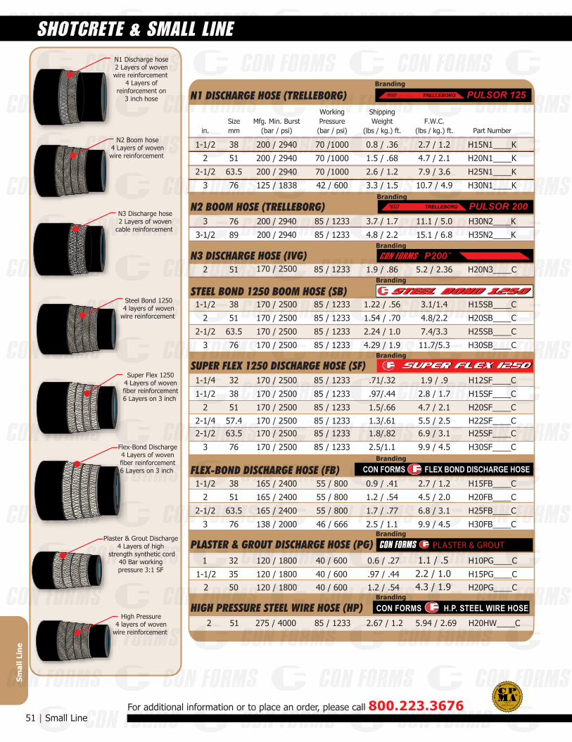
Steel Bond 12504 layers of woven
wire reinforcement
N1 Discharge hose2 Layers of wovenwire reinforcement
4 Layers ofreinforcement on
3 inch hose
N2 Boom hose4 Layers of wovenwire reinforcement
N3 Discharge hose2 Layers of woven
cable reinforcement
Super Flex 12504 Layers of wovenfiber reinforcement6 Layers on 3 inch
Flex-Bond Discharge4 Layers of wovenfiber reinforcement6 Layers on 3 inch
Plaster & Grout Discharge4 Layers of high
strength synthetic cord40 Bar workingpressure 3:1 SF
High Pressure4 layers of woven
wire reinforcement
51 | Small LineFor additional information or to place an order, please call 800.223.3676
Smal
l Lin
e
SHOTCRETE & SMALL LINE
STEEL BOND 1250 BOOM HOSE (SB)
85 / 1233
85 / 1233
85 / 1233
85 / 1233170 / 2500
170 / 2500
170 / 2500
170 / 2500
1-1/2 1.22 / .56 3.1/1.4 H15SB____C
2 1.54 / .70 4.8/2.2 H20SB____C
2-1/2 2.24 / 1.0 7.4/3.3 H25SB____C
3 4.29 / 1.9 11.7/5.3 H30SB____C
38
51
63.5
76
Branding
1-1/4 85 / 1233
85 / 1233
85 / 1233
85 / 1233
85 / 1233
170 / 2500
170 / 2500
170 / 2500
170 / 2500
170 / 2500
.71/.32 1.9 / .9 H12SF____C
1-1/2 .97/.44 2.8 / 1.7 H15SF____C
2 1.5/.66 4.7 / 2.1 H20SF____C
2-1/2 1.8/.82 6.9 / 3.1 H25SF____C
3 2.5/1.1 9.9 / 4.5 H30SF____C
32
38
51
63.585 / 1233170 / 25002-1/4 1.3/.61 5.5 / 2.5 H22SF____C57.4
76
SUPER FLEX 1250 DISCHARGE HOSE (SF)Branding
1-1/2 165 / 2400 55 / 800 0.9 / .41 2.7 / 1.2 H15FB____C
2 165 / 2400 55 / 800 1.2 / .54 4.5 / 2.0 H20FB____C
2-1/2 165 / 2400 55 / 800 1.7 / .77 6.8 / 3.1 H25FB____C
3 138 / 2000 46 / 666 2.5 / 1.1 9.9 / 4.5 H30FB____C
1 120 / 1800 40 / 600 0.6 / .27 H10PG____C
1-1/2 120 / 1800 40 / 600 .97 / .44 H15PG____C
32
35
2 120 / 1800 40 / 600 1.2 / .54 H20PG____C50
38
51
63.5
76
Branding
CON FORMS FLEX BOND DISCHARGE HOSEFLEX-BOND DISCHARGE HOSE (FB)
Mfg. Min. Burst(bar / psi)
WorkingPressure(bar / psi) Part Number
1-1/2 200 / 2940 70 /1000 0.8 / .36 2.7 / 1.2 H15N1____K
2 200 / 2940 70 /1000 1.5 / .68 4.7 / 2.1 H20N1____K
2-1/2 200 / 2940 70 /1000 2.6 / 1.2 7.9 / 3.6 H25N1____K
3 125 / 1838 42 / 600 3.3 / 1.5 10.7 / 4.9 H30N1____K
ShippingWeight
(lbs / kg.) ft.F.W.C.
(lbs / kg.) ft.Size
in. mm
38
51
63.5
76
85 / 1233170 / 25002 1.9 / .86 H20N3____C5.2 / 2.3651
763 200 / 2940 85 / 1233 3.7 / 1.7 11.1 / 5.0 H30N2____K
3-1/2 200 / 2940 85 / 1233 4.8 / 2.2 15.1 / 6.8 H35N2____K89
N1 DISCHARGE HOSE (TRELLEBORG)Branding
PULSOR 125TRELLEBORGT
N2 BOOM HOSE (TRELLEBORG)Branding
PULSOR 200TRELLEBORGT
N3 DISCHARGE HOSE (IVG) P200™
Branding
Branding
PLASTER & GROUT DISCHARGE HOSE (PG)
Branding
HIGH PRESSURE STEEL WIRE HOSE (HP)
PLASTER & GROUT
85 / 1233275 / 40002 2.67 / 1.2 5.94 / 2.69 H20HW____C51
CON FORMS H.P. STEEL WIRE HOSE
1.1 / .52.2 / 1.04.3 / 1.9
ASME B30.27-2014
CERTIFIEDD
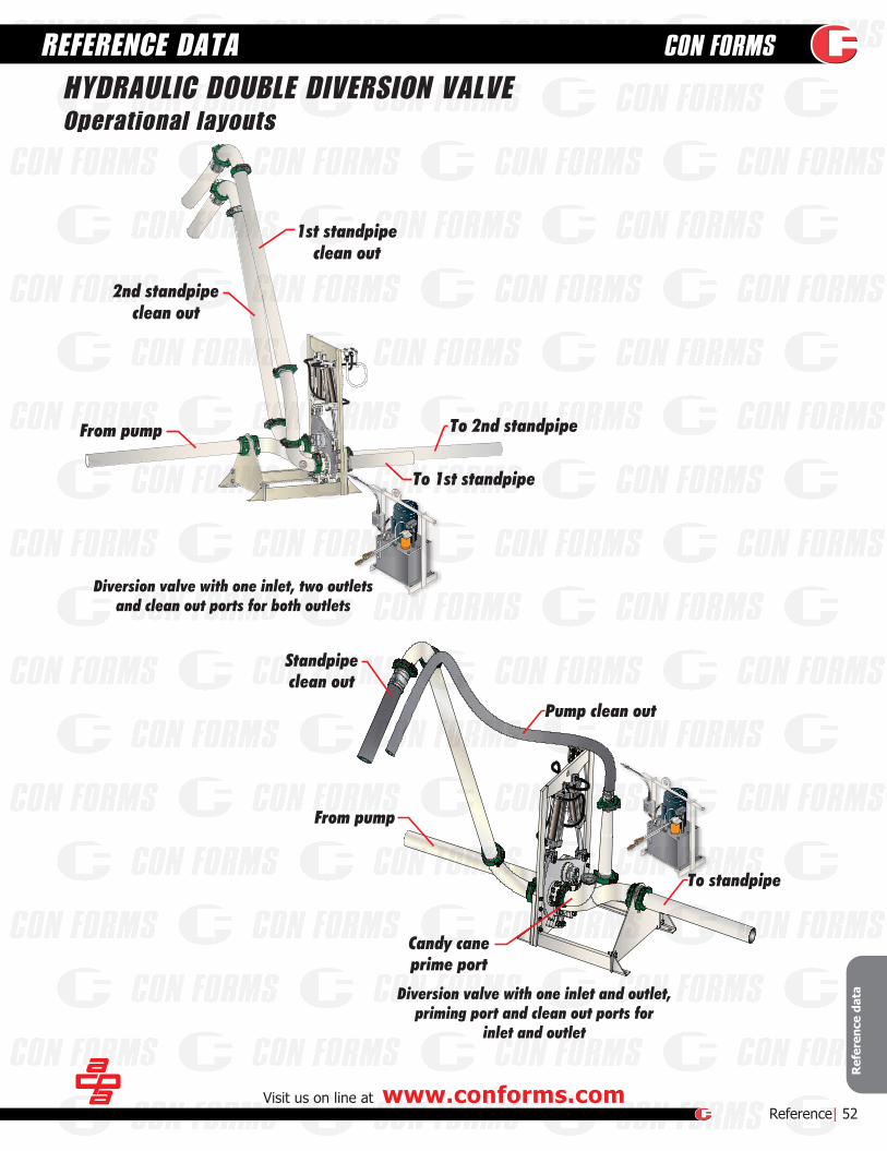
Diversion valve with one inlet and outlet,priming port and clean out ports for
inlet and outlet
To standpipe
Pump clean out
Standpipeclean out
From pump
Candy caneprime port
Diversion valve with one inlet, two outletsand clean out ports for both outlets
From pump
1st standpipeclean out
2nd standpipeclean out
To 1st standpipe
To 2nd standpipe
REFERENCE DATA
Ref
eren
ce d
ata
Visit us on line at www.conforms.comReference| 52
HYDRAULIC DOUBLE DIVERSION VALVEOperational layouts

53 | Reference DataFor additional information or to place an order, please call 800.223.3676
Ref
eren
ce d
ata
REFERENCE DATA PIPE and HOSE PART NUMBER CHART
SAMPLE PART NUMBER:HOSE
SAMPLE PART NUMBER:PIPE
SECTION 4: OVERALL LENGTH (FEET)
03 = 3'04 = 4'05 = 5'06 = 6'07 = 7'08 = 8'09 = 9'10 = 10'11 = 11'12 = 12'
99 = 99'100 = 100'
...
SECTION 5: END STYLE
M1 = Metric (1 end)D1 = Hevi-Duty™ (1 end)M2 = Metric (2 ends)D2 = Hevi-Duty (2 ends)TM = Tapered MetricTD = Tapered Hevi-DutyRD = Tapered Neck Hevi-DutyRM = Tapered Metric
SECTION 2: INSIDE DIAMETER
10 = 1"12 = 1.25"15 = 1.5"20 = 2"25 = 2.5"30 = 3"35 = 3.5"40 = 4"45 = 4.5"50 = 5"60 = 6"
SECTION 3: HOSE TYPE
FB = Flex Bond DischargeS1 = Steel Bond Discharge
SF = Super Flex 1250SB = Steel Bond 1250
S2 = Steel Bond BoomN1 = Trelleborg DischargeN2 = Trelleborg BoomN3 = IVG Small LineRN = Ruff-Neck ReducingHW = 2" High PressurePG = Plaster & Grout
SECTION 6
C = Steel Bond / Flex BondK = Trelleborg / Kleber
*H50S110D2C = 10' length of 5.0" I.D. Steelbond Discharge Hose with 2 Hevi-Duty Ends
*
SECTION 1
H = Hose
HSECTION 1
50SECTION 2
S1SECTION 3
10SECTION 4
D2SECTION 5
CSECTION 6
SECTION 5: END STYLE
D = Hevi-Duty™M = Metric
SECTION 6
H = Hardened(blank) = Non-hardened
*only used for products that have both a hardened and a non-hardened option. Leave
blank for TW and CCI products.
SECTION 4: OVERALL LENGTH (INCHES)
10 INCH INCREMENTS
B1 INCH
INCREMENTS
8
0 = 0"1 = 10"2 = 20"3 = 30"4 = 40"5 = 50"6 = 60"7 = 70"8 = 80"9 = 90"A = 100"B = 110"C = 120"D = 130"E = 140"F = 150"G = 160"
06 = 1/16"12 = 1/8"18 = 3/16"25 = 1/4"31 = 5⁄16"37 = 3/8"43 = 7/16"50 = 1/2"56 = 9/16"62 = 5/8"68 = 11/16"75 = 3/4"81 = 13/16"87 = 7/8"93 = 15/16"
FRACTIONALINCREMENTS
12
H = 170"J = 180"K = 190"L = 200"M = 210"N = 220"P = 230"Q = 240"R = 250"S = 260"T = 270"U = 280"V = 290"W = 300"X = 310"Y = 320"Z = 330"
0 = 0"1 = 1"2 = 2"3 = 3"4 = 4"5 = 5"6 = 6"7 = 7"8 = 8"9 = 9"
*B48TWB812M = 118.12" (3 meter) section of 4.8" I.D. TW325 Boom Pipe with Metric Ends
SECTION 1
SECTION 2: INSIDE DIAMETER
SECTION 3: WALL TYPE
4 = 4.0"44 = 4.4"46 = 4.6"48 = 4.8"50 = 5.0"60 = 6.0"
TW = Standard WeightTWL = Light Weight
TWUL = Ultra Light WeightCC = (Chrome Carbide)XW = Heavy Weight
9 = 9 Gauge7 = 7 Gauge
B = Boom truckBC = Ultra Plus product
BCC = Chrome Carbide Insert (CCI)
BSECTION 1
48SECTION 2
TWSECTION 3
B812SECTION 4
MSECTION 5 SECTION 6
*
ASME B30.27-2014
CERTIFIEDD
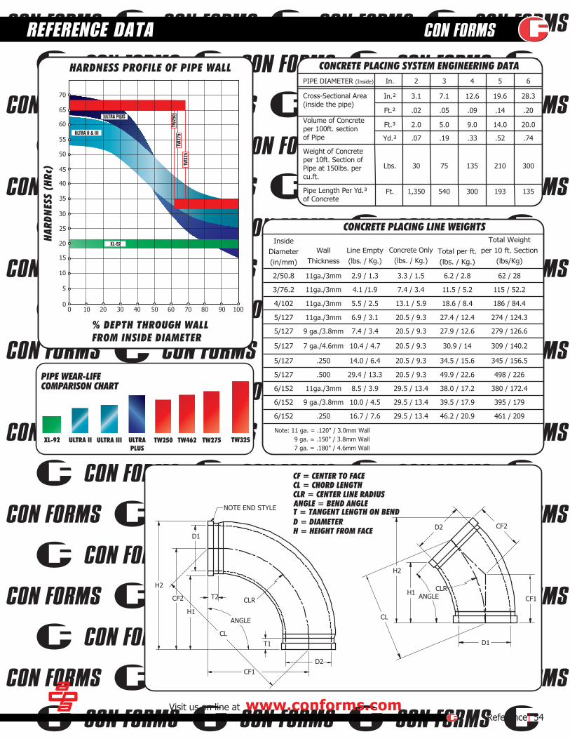
65432In.PIPE DIAMETER (Inside)
Ft.
Lbs.
Yd.³
Ft.³
Ft.²
In.²
135
300
.74
20.0
.20
28.3
193
210
.52
14.0
.14
19.6
300
135
.33
9.0
.09
12.6
540
75
.19
5.0
.05
7.1
1,350
30
.07
2.0
.02
3.1Cross-Sectional Area(inside the pipe)
Volume of Concreteper 100ft. sectionof Pipe
Weight of Concreteper 10ft. Section ofPipe at 150lbs. percu.ft.
CONCRETE PLACING SYSTEM ENGINEERING DATA
Pipe Length Per Yd.³of Concrete
Concrete Only(lbs. / Kg.)
CONCRETE PLACING LINE WEIGHTS
Note: 11 ga. = .120" / 3.0mm Wall 9 ga. = .150" / 3.8mm Wall 7 ga. = .180" / 4.6mm Wall
InsideDiameter(in/mm)
WallThickness
Line Empty(lbs. / Kg.)
Total per ft.(lbs. / Kg.)
Total Weightper 10 ft. Section
(lbs/Kg)
5/127
4/102
3/76.2
2/50.8
274 / 124.3
186 / 84.4
115 / 52.2
62 / 28
27.4 / 12.4
18.6 / 8.4
11.5 / 5.2
6.2 / 2.8
20.5 / 9.3
13.1 / 5.9
7.4 / 3.4
3.3 / 1.5
6.9 / 3.1
5.5 / 2.5
4.1 /1.9
2.9 / 1.311ga./3mm
11ga./3mm
11ga./3mm
11ga./3mm
5/127
5/127
5/127
5/127
498 / 226
345 / 156.5
309 / 140.2
279 / 126.6
49.9 / 22.6
34.5 / 15.6
30.9 / 14
27.9 / 12.6
20.5 / 9.3
20.5 / 9.3
20.5 / 9.3
20.5 / 9.3
29.4 / 13.3
14.0 / 6.4
10.4 / 4.7
7.4 / 3.4
.500
.250
7 ga./4.6mm
9 ga./3.8mm
6/152
6/152
461 / 209
395 / 179
46.2 / 20.9
39.5 / 17.9
29.5 / 13.4
29.5 / 13.4
16.7 / 7.6
10.0 / 4.5
.250
9 ga./3.8mm
6/152 380 / 172.438.0 / 17.229.5 / 13.48.5 / 3.911ga./3mm
CF = CENTER TO FACECL = CHORD LENGTHCLR = CENTER LINE RADIUSANGLE = BEND ANGLET = TANGENT LENGTH ON BENDD = DIAMETERH = HEIGHT FROM FACE
H2
H1
CL
D1
D2
CLRANGLE
CF2
CF1
NOTE END STYLE
H2
H1
CL
D1
D2
CLR
ANGLE
CF2
CF1
T2
T1
Visit us on line at www.conforms.comReference| 54
XL-92 ULTRA II ULTRA III ULTRAPLUS
TW275 TW325
PIPE WEAR-LIFECOMPARISON CHART
TW250 TW462
HAR
DNES
S (H
Rc)
% DEPTH THROUGH WALLFROM INSIDE DIAMETER
HARDNESS PROFILE OF PIPE WALL
70
65
60
55
50
45
40
35
30
25
20
15
10
5
00 10 20 30 40 50 60 70 80 90 100
REFERENCE DATA
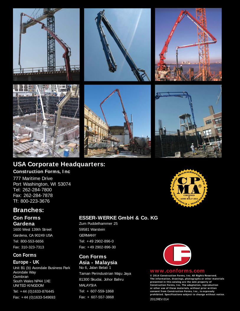
USA Corporate Headquarters:Construction Forms, Inc777 Maritime DrivePort Washington, WI 53074Tel: 262-284-7800Fax: 262-284-7878Tf: 800-223-3676
Con FormsGardena1600 West 139th Street
Gardena, CA 90249 USA
Tel: 800-553-6656
Fax: 310-323-7313
Branches:
Con FormsEurope - UK
Con FormsAsia - MalaysiaNo 6, Jalan Belati 1
Taman Perindustrian Maju Jaya
81300 Skudai, Johor Bahru
MALAYSIA
Tel: + 607-559-1868
Fax: + 607-557-3868
ESSER-WERKE GmbH & Co. KGZum Puddelhammer 25
59581 Warstein
GERMANY
Tel: +49 2902-896-0
Fax: +49 2902-896-30
Unit B1 (b) Avondale Business ParkAvondale WayCwmbranSouth Wales NP44 1XEUNITED KINGDOM
Tel: +44 (0)1633-876445
Fax: +44 (0)1633-549693
www.conforms.com© 2014 Construction Forms, Inc. All Rights Reserved.The information, drawings, photographs or other materialspresented in this catalog are the sole property ofConstruction Forms, Inc. The adaptation, reproductionor other use of these materials, without prior writtenconsent from Construction Forms, Inc., is expresslyprohibited. Specifications subject to change without notice.
2012REV.014
ASME B30.27-2014
CERTIFIEDD
Top Related