


Languages
Pages
Legal

LCF Touch Modbus (from firmware version 1.6) Electronic Fan Coil Thermostat with Touch Display (Flush mounting)
Thermokon Sensortechnik GmbH, Platanenweg 1, 35756 Mittenaar, Germany · tel: +49 2778 6960-0 · fax: -400 · www.thermokon.com · [email protected] LCF_TOUCH_Modbus_Datasheet_en.docx © 2016
Datasheet
Subject to technical alteration
Issue date: 28.06.2016
Application
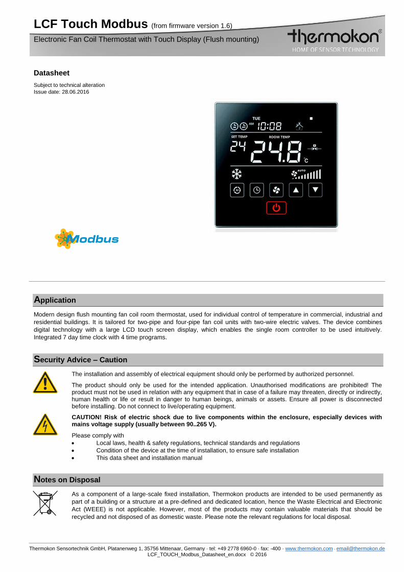
Modern design flush mounting fan coil room thermostat, used for individual control of temperature in commercial, industrial and
residential buildings. It is tailored for two-pipe and four-pipe fan coil units with two-wire electric valves. The device combines
digital technology with a large LCD touch screen display, which enables the single room controller to be used intuitively.
Integrated 7 day time clock with 4 time programs.
Security Advice – Caution
The installation and assembly of electrical equipment should only be performed by authorized personnel.
The product should only be used for the intended application. Unauthorised modifications are prohibited! The product must not be used in relation with any equipment that in case of a failure may threaten, directly or indirectly, human health or life or result in danger to human beings, animals or assets. Ensure all power is disconnected before installing. Do not connect to live/operating equipment.
CAUTION! Risk of electric shock due to live components within the enclosure, especially devices with mains voltage supply (usually between 90..265 V).
Please comply with
Local laws, health & safety regulations, technical standards and regulations
Condition of the device at the time of installation, to ensure safe installation
This data sheet and installation manual
Notes on Disposal
As a component of a large-scale fixed installation, Thermokon products are intended to be used permanently as
part of a building or a structure at a pre-defined and dedicated location, hence the Waste Electrical and Electronic
Act (WEEE) is not applicable. However, most of the products may contain valuable materials that should be
recycled and not disposed of as domestic waste. Please note the relevant regulations for local disposal.
Page 2 / 10 Issue date: 28.06.2016
Thermokon Sensortechnik GmbH, Platanenweg 1, 35756 Mittenaar, Germany · tel: +49 2778 6960-0 · fax: -400 · www.thermokon.com · [email protected] LCF_TOUCH_Modbus_Datasheet_en.docx © 2016
General remarks concerning sensors
Especially with regard to passive sensors in 2-wire conductor versions, the wire resistance of the supply wire has to be
considered. If necessary the wire resistance has to be compensated by the follow-up electronics. Due to self-heating, the wire
current affects the measurement accuracy, so it should not exceed 1 mA.
When using lengthy connection wires (depending on the cross section used) the measuring result might be falsified due to a
voltage drop at the common GND-wire (caused by the voltage current and the line resistance). In this case, 2 GND-wires must
be wired to the sensor - one for supply voltage and one for the measuring current.
Sensing devices with a transducer should always be operated in the middle of the measuring range to avoid deviations at the
measuring end points. The ambient temperature of the transducer electronics should be kept constant. The transducers must be
operated at a constant supply voltage (±0,2 V). When switching the supply voltage on/off, onsite power surges must be avoided.
Remarks to Room Sensors
Location and Accuracy of Room Sensors
The room sensor should be mounted in a suitable location for measuring accurate room temperature. The accuracy of the
temperature measurement also depends directly on the temperature dynamics of the wall. It is important, that the back plate is
completely flush to the wall so that the circulation of air occurs through the vents in the cover. Otherwise, deviations in
temperature measurement will occur due to uncontrolled air circulation. Also the temperature sensor should not be covered by
furniture or similar devices. Mounting next to doors (due to draught) or windows (due to colder outside wall) should be avoided.
The temperature dynamics of the wall will influence the temperature measurement. Various wall types (brick, concrete, dividing
and hollow brickwork) all have different behaviours with regards to thermal variations.
Surface and Flush Mounting
The temperature dynamics of the wall influence the measurement result of the sensor. Various wall types (brick, concrete,
dividing and hollow brickwork) have different behaviours with regard to thermal variations. A solid concrete wall responds to
thermal fluctuations within a room in a much slower way than a light-weight structure wall. Room temperature sensors installed in
flush boxes have a longer response time to thermal variations. In extreme cases they detect the radiant heat of the wall even if
the air temperature in the room is lower for example. The quicker the dynamics of the wall (temperature acceptance of the wall)
or the longer the selected inquiry interval of the temperature sensor is the smaller the deviations limited in time are.
Technical Data
Measuring values temperature
Output switch contact 5x normally open contact, 240 V Last max. 3 A, 2x heating/cooling, 3x FanCoil
Network technology RS485 Modbus, RTU, half-duplex, baud rate 4.800, 9.600, 19.200 or 38.400,
parity: non (2 stopbits), even or odd (1 stopbit)
Power supply 90..265 V ~
Power consumption 0,9 VA (265 V ~)
Measuring range temperature +1..+50 °C
Accuracy temperature ±0.1 °C (typ. at 21 °C)
Inputs inputs for change-over sensor (NTC 10 K)
Control functions setpoint adjustment +1..+50 °C, (Default +16..+30 °C)
Display LCD-module with Touch and LED-illumination
Enclosure ABS, scratch-resistant acrylic glass
Protection IP20 according to EN 60529
Connection electrical terminal block max. 1,5 mm²
Ambient condition -10..+50 °C, max. 85% rH non-condensing
Weight 160 g
Mounting flush mounted with standard EU box (Ø=55 mm)
Mounting Advices
For installing or repairing, please make sure the power for the thermostat has been turned off.
1. Insert the screw driver in the plastic teeth of the thermostat to open the enclosure.
2. Please follow the wiring diagram to connect the wires.
3. Fix the thermostat base plate to the wall by using the four screw holes with a distance between the axes of 60mm.
4. Fasten base plate and front cover. Do not press the panel in order to protect LCD.

Issue date: 28.06.2016 Page 3 / 10
Thermokon Sensortechnik GmbH, Platanenweg 1, 35756 Mittenaar, Germany · tel: +49 2778 6960-0 · fax: -400 · www.thermokon.com · [email protected] LCF_TOUCH_Modbus_Datasheet_en.docx © 2016
Connection Plan
LCF Touch Modbus – Auto mode wiring diagram for 2-pipe fan coil
LCF Touch Modbus – Manual mode wiring diagram for 2-pipe fan coil
LCF Touch Modbus – Auto change-over mode Heating/Cooling wiring diagram for 4-pipe fan coil

Page 4 / 10 Issue date: 28.06.2016
Thermokon Sensortechnik GmbH, Platanenweg 1, 35756 Mittenaar, Germany · tel: +49 2778 6960-0 · fax: -400 · www.thermokon.com · [email protected] LCF_TOUCH_Modbus_Datasheet_en.docx © 2016
Commissioning
Setting parameter No. 13, the selection of the fan coil system has to be done. 2-pipe or 4-pipe systems can be selected.
Hysteresis: 1 K + 1 minute delay
Operation in 2-pipe system (parameter No. 13 set to 2):
When using a change-over sensor, the thermostat can detect whether the fluid is convenient for cooling or for heating:
Operation without a change-over sensor:
In the 2-pipe system, a fluid can be used only for cooling or only for heating depending on the temperature of the fluid.
When no change-over sensor is used, heating, cooling and ventilating mode have to be selected manually using MODE
settings (depending on the desired action of the heating/cooling system).
Operation with a change-over sensor (Auto change-over mode):
By using an change-over sensor, the system recognizes, whether the fluid has the necessary temperature for cooling or
for heating. The heating or cooling control sequence will be automatically selected. When temperature is ≤+19 °C,
cooling mode is activated; when the temperature is ≥+30 °C, the heating mode is active. Configurable via Holding
Register 40010|40011. MODE key has no function in this case.
Operation in 4-pipe system (parameter No. 13 set to 4):
The thermostat switches automatically between cooling and heating. A time delay of approx.. 1 min between cooling/heating
mode changes is implemented to ensure safe and eco-friendly operation. Parameter No.14 has to be set to 1 to enable the
device for operating in auto mode.
Mode selection:
Manual Mode: 2-pipe-System: Cooling Ventilating Heating
4-pipe-System: Cooling Ventilating Heating Auto change-over mode (only when parameter No.
14 is set to 1!)
AUTO-Mode: The mode will be selected automatically.
Fan Stage selection:
In Cooling, Heating or Auto mode, following fan stages can be selected: Low Med Hi Auto
In Ventilation mode, following fan stages can be selected: Low Med Hi
Ventilation mode can be deactivated by setting parameter No. 15 to “0”.
Auto mode: ∆T ≤ 1°C Low
1 °C < ∆T < 3 °C Med
∆T ≥ 3 °C Hi
Display °C or °F
Display of the units °C or °F can be selected using parameter No. 12. Fahrenheit temperature display range is 32..99 °F, °C
temperature display range is 0..50 °C. Factory default is °C.
Note: Under parameter No.1 the temperature offset can be adjusted. This feature should be used if the temperature at the
mounting place of the Room Thermostat is not accurate to the average room temperature.
Temperature Room Temperature set point selection:

Issue date: 28.06.2016 Page 5 / 10
Thermokon Sensortechnik GmbH, Platanenweg 1, 35756 Mittenaar, Germany · tel: +49 2778 6960-0 · fax: -400 · www.thermokon.com · [email protected] LCF_TOUCH_Modbus_Datasheet_en.docx © 2016
By pressing “▲” or “▼” button, the room temperature set point can be adjusted. °C Range is 16..30 °C, Fahrenheit temperature
range is 60..86 °F.
By using parameter No. 4 and No. 5, the set point ranges can be adjusted.
Fan stage/Valve control selection:
Under Fan operation “INDEPENDENT”, the fan will always operate according to the selected or automatically assigned fan
stage; under Fan operation “DEPENDENT”, the fan will be tuned off in case the valve is closed. If the valve is open, the fan will
operate according to the selected or automatically assigned fan stage.
By using parameter No. 16, the “INDEPENDENT” or “DEPENDENT” mode can be selected.
Key lock selection (No. 2), power failure selection (No. 3), screen save mode (No. 7) can be set by Parameters.
Also in parameter No. 7 you are able to read the LCD display status.
Sensor failure alarm:
If the temperature sensor is out of range, the thermostat will switch off the fan and close the valve, error code “E01” will be
shown.
Language selection
You can change the display language with parameter No. 11.
Set time format
With parameter No. 8 the time format to 12h or 24h can be defined.
Time setting
Press the “ ” button, to set the time. The changing parameter is blinking, press “▲”or“▼”-button to set:
Order: Year→month→day date→day name→hour→minute→Timer ON hour minute→Timer OFF hour minute →year→…
In case of power loss, the time is backed up for max 2 years.
Set timer
Press the “ ”-button, the parameter to be changed is flashing, the timer will be set on or off.
Finish: Timer on, LCD display ;
Finish: Timer off, LCD display ;
Leave menu:
To delete timer on/off, press the “ ” button, the parameter to be changed is flashing. Then select “ ” or“ , set the time
like the following image to leave the timer mode: “ ” .
The system saves the user settings to set the timer on / off automatically.

Page 6 / 10 Issue date: 28.06.2016
Thermokon Sensortechnik GmbH, Platanenweg 1, 35756 Mittenaar, Germany · tel: +49 2778 6960-0 · fax: -400 · www.thermokon.com · [email protected] LCF_TOUCH_Modbus_Datasheet_en.docx © 2016
Selection timer on / off
The timer on/off has 2 options to be selected: single action or rule.
To set, please look up parameter No. 9 in the parameter table.
7 days 4 periods programmable timer
One day is split into 4 periods. The user can set temperature for every period individually.
To set the time zones, please look up parameter No. 10 in the parameter table.
If the user has set a set temperature during operation, the current period runs with the last set temperature. The next period will
adopt the changed settings.
Please follow the instructions below:
Press the “ ” button for more than 5 seconds, the parameter to be changed is flashing. Press the “ ” button
again, the value needs to be changed, appears. (hour, minute, period). Changes in value by pressing ▲” or“▼”. The
following 4 programmable periods can be set.
→ hour → minute →temperature 1 → hour→ minute→ temperature 2
→ hour→ minute→ temperature 3 → hour → minute → temperature 4
Individual passwords setting
Factory default :260
Configuration
Parameters
= MODE button
In order to change the parameters, please press the MODE button for more than 5 seconds. Please follow figure below. If you
are asked to enter the password, use “▲”or “▼” key to enter each digit of the password. Press MODE button to switch to the
next digit.
The standard password is 260.
If the password has been entered correctly, you will see the parameter settings screen as below shown:

Issue date: 28.06.2016 Page 7 / 10
Thermokon Sensortechnik GmbH, Platanenweg 1, 35756 Mittenaar, Germany · tel: +49 2778 6960-0 · fax: -400 · www.thermokon.com · [email protected] LCF_TOUCH_Modbus_Datasheet_en.docx © 2016
Press the MODE button to select the parameter you would like to change. Then use “▲” or “▼” to change the parameter. Please
refer to the parameter table on the following page:
No. Name of parameter Parameter definition Factory default
1 Temperature offset: Range -20..+20 K 0
2 Key-lock: 0- unlocked
1- lock on / off
2- lock mode
3- lock clock
4- lock fan speed
5- lock temperature setting
6- lock all keystrokes
0
3 Power failure: 0- stay power off
1- restore last status before power failure
2- turn power on after power failure
1
4 Upper temperature limit: Range: +1..+50 °C / +34..99 °F 30 °C / 86 °F
5 Lower temperature limit: Range: +1..+50 °C / +34..99 °F 16 °C / 60 °F
6 LCD backlight delay: 10..150 seconds 20 seconds
7 Screensaver mode: 0- display off
1- room temperature
2- display clock, room temperature
3- display on
0
8 Time format: 12- 12 hours
24- 24 hours
12
9 Timer on / off: 0- once
1- loop
0
10 7 days, 4 periods
programmable:
0- forbidden
1- allowed
0
11 Display language: 1- English 1
12 Temperature format: 0- °C
1- °F
0
13 Selection Fan Coil: 2- 2-pipe Fan Coil, heating/cooling
4- 4-pipe Fan Coil, heating/cooling
6- 2-pipe Fan Coil cooling+electri-heater
2
14 Auto cooling & heating
modus:
0- deactivated
1- activated
0
15 Fan modus: 0- deactivated
1- activated
1
16 Fan on/off
selective
0-valve stop does chain fan,1-Valve stop chain fan 0
17 Temporarily not defined 0
18 Communication: ID.1.. ID.247 1
19 Baud rate: 1- 4800 bps; 2- 9600 bps; 3- 19200 bps; 4- 38400 bps 2
20 Parity 0-no parity 1-odd parity 2-even parity 0
21 Summer/winter time 0-fordibben 1-allow 1
22 Individual password setting 001-999 260
23 Stopbit 1=1bit, 2=2bit 2
Page 8 / 10 Issue date: 28.06.2016
Thermokon Sensortechnik GmbH, Platanenweg 1, 35756 Mittenaar, Germany · tel: +49 2778 6960-0 · fax: -400 · www.thermokon.com · [email protected] LCF_TOUCH_Modbus_Datasheet_en.docx © 2016
All parameters are stored within an EEPROM (electrically erasable programmable ROM), ensuring no data loss if the Thermostat
is powered off.
Communication Modbus
For configuration of the Modbus communication, please look up parameter No. 18 in the parameter table.
Communication-section 1..247
Factory default: 1
Address 0: broadcast address
Communication-Interface: RS485
Communication-Protocol: Modbus-RTU
Baud Rate: 4800 bps / 9600 bps / 19200 bps / 38400 bps (optional)
Factory default: 9600 bps
Parity: no parity / odd parity / straight parity (optional)
Factory default: no parity
Data: 8 bit
Stop: 2 bit
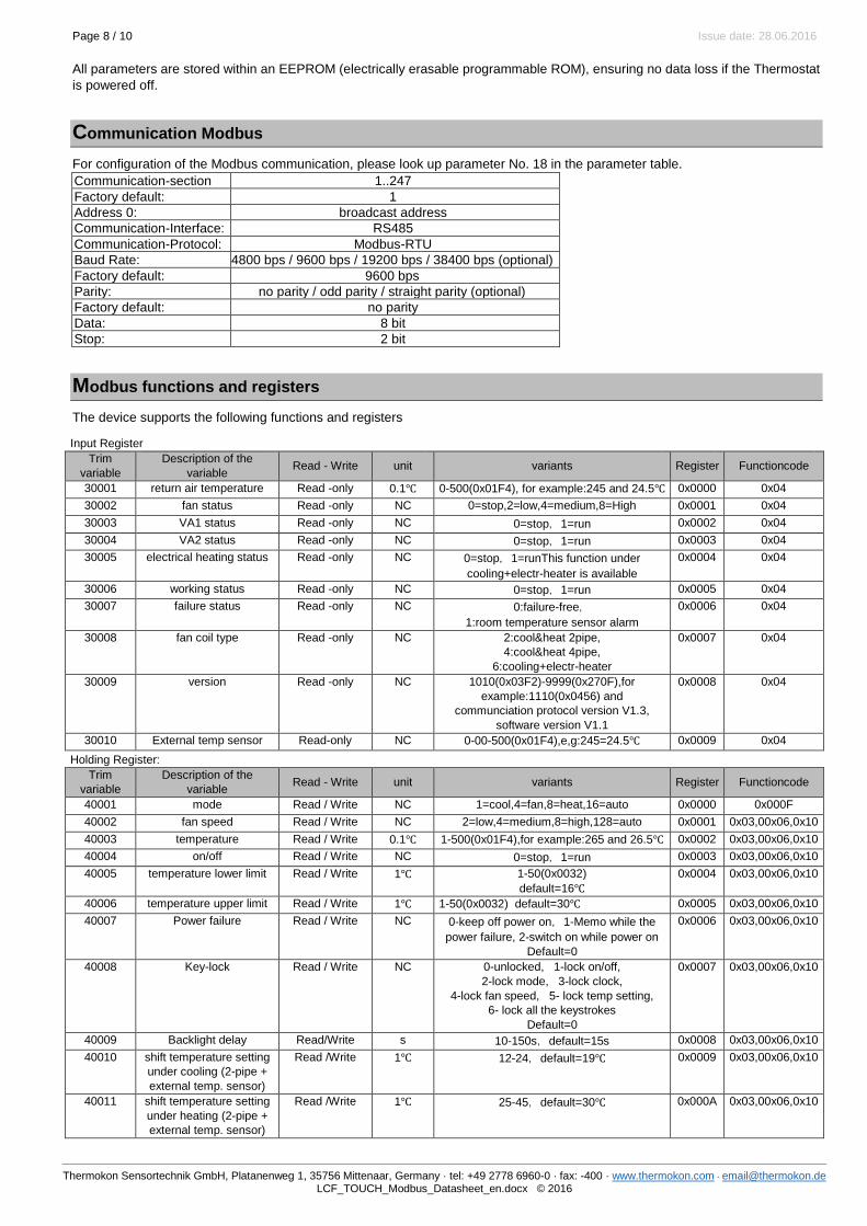
Modbus functions and registers
The device supports the following functions and registers
Input Register
Trim
variable
Description of the
variable Read - Write unit variants Register Functioncode
30001 return air temperature Read -only 0.1℃ 0-500(0x01F4), for example:245 and 24.5℃ 0x0000 0x04
30002 fan status Read -only NC 0=stop,2=low,4=medium,8=High 0x0001 0x04
30003 VA1 status Read -only NC 0=stop,1=run 0x0002 0x04
30004 VA2 status Read -only NC 0=stop,1=run 0x0003 0x04
30005 electrical heating status Read -only NC 0=stop,1=runThis function under
cooling+electr-heater is available
0x0004 0x04
30006 working status Read -only NC 0=stop,1=run 0x0005 0x04
30007 failure status Read -only NC 0:failure-free,
1:room temperature sensor alarm
0x0006 0x04
30008 fan coil type Read -only NC 2:cool&heat 2pipe,
4:cool&heat 4pipe,
6:cooling+electr-heater
0x0007 0x04
30009 version Read -only NC 1010(0x03F2)-9999(0x270F),for
example:1110(0x0456) and
communciation protocol version V1.3,
software version V1.1
0x0008 0x04
30010 External temp sensor Read-only NC 0-00-500(0x01F4),e,g:245=24.5℃ 0x0009 0x04
Holding Register:
Trim
variable
Description of the
variable Read - Write unit variants Register Functioncode
40001 mode Read / Write NC 1=cool,4=fan,8=heat,16=auto 0x0000 0x000F
40002 fan speed Read / Write NC 2=low,4=medium,8=high,128=auto 0x0001 0x03,00x06,0x10
40003 temperature Read / Write 0.1℃ 1-500(0x01F4),for example:265 and 26.5℃ 0x0002 0x03,00x06,0x10
40004 on/off Read / Write NC 0=stop,1=run 0x0003 0x03,00x06,0x10
40005 temperature lower limit Read / Write 1℃ 1-50(0x0032)
default=16℃
0x0004 0x03,00x06,0x10
40006 temperature upper limit Read / Write 1℃ 1-50(0x0032) default=30℃ 0x0005 0x03,00x06,0x10
40007 Power failure Read / Write NC 0-keep off power on,1-Memo while the
power failure, 2-switch on while power on
Default=0
0x0006 0x03,00x06,0x10
40008 Key-lock Read / Write NC 0-unlocked, 1-lock on/off,
2-lock mode, 3-lock clock,
4-lock fan speed, 5- lock temp setting,
6- lock all the keystrokes
Default=0
0x0007 0x03,00x06,0x10
40009 Backlight delay Read/Write s 10-150s,default=15s 0x0008 0x03,00x06,0x10
40010 shift temperature setting
under cooling (2-pipe +
external temp. sensor)
Read /Write 1℃ 12-24,default=19℃ 0x0009 0x03,00x06,0x10
40011 shift temperature setting
under heating (2-pipe +
external temp. sensor)
Read /Write 1℃ 25-45,default=30℃ 0x000A 0x03,00x06,0x10
Issue date: 28.06.2016 Page 9 / 10
Thermokon Sensortechnik GmbH, Platanenweg 1, 35756 Mittenaar, Germany · tel: +49 2778 6960-0 · fax: -400 · www.thermokon.com · [email protected] LCF_TOUCH_Modbus_Datasheet_en.docx © 2016
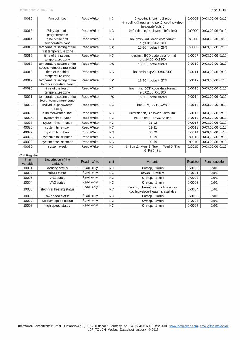
40012 Fan coil type Read /Write NC 2=cooling&heating 2-pipe
4=cooling&heating 4-pipe ,6=cooling+elec-
heater,default=2
0x000B 0x03,00x06,0x10
40013 7day 4periods
programmable
Read /Write NC 0=forbidden,1=allowed ,default=0 0x000C 0x03,00x06,0x10
40014 time of the first
temperature zone
Read /Write NC hour:min,BCD code data format
e,g:08:30=0x0830
0x000D 0x03,00x06,0x10
40015 temperature setting of the
first temperature zone
Read /Write 1℃ 16-30,default=25℃ 0x000E 0x03,00x06,0x10
40016 time of the second
temperature zone
Read /Write NC hour:min, BCD code data format
e,g:14:00=0x1400
0x000F 0x03,00x06,0x10
40017 temperature setting of the
second temperature zone
Read /Write 1℃ 16-30,default=26℃ 0x0010 0x03,00x06,0x10
40018 time of the third
temperature zone
Read /Write NC hour:min,e,g:20:00=0x2000 0x0011 0x03,00x06,0x10
40019 temperature setting of the
third temperature zone
Read /Write 1℃ 16-30,default=27℃ 0x0012 0x03,00x06,0x10
40020 time of the fourth
temperature zone
Read /Write NC hour:min, BCD code data format
e,g:02:00=0x0200
0x0013 0x03,00x06,0x10
40021 temperature setting of the
fourth temperature zone
Read /Write 1℃ 16-30,default=28℃ 0x0014 0x03,00x06,0x10
40022 Individual passwords
setting
Read /Write NC 001-999,defaul=260 0x0015 0x03,00x06,0x10
40023 Summer/winter time Read /Write NC 0=forbidden,1=allowed ,default=1 0x0016 0x03,00x06,0x10
40024 system time-- year Read /Write NC 2000-2099,default=2015 0x0017 0x03,00x06,0x10
40025 system time--month Read /Write NC 01-12 0x0018 0x03,00x06,0x10
40026 system time--day Read /Write NC 01-31 0x0019 0x03,00x06,0x10
40027 system time-hour Read /Write NC 00-23 0x001A 0x03,00x06,0x10
40028 system time-minutes Read /Write NC 00-59 0x001B 0x03,00x06,0x10
40029 system time--seconds Read /Write NC 00-59 0x001C 0x03,00x06,0x10
40030 system week Read /Write NC 1=Sun ,2=Mon ,3=Tue ,4=Wed 5=Thu
6=Fri 7=Sat
0x001D 0x03,00x06,0x10
Coil Register
Trim
variable
Description of the
variable Read - Write unit variants Register Functioncode
10001 working status Read -only NC 0=stop,1=run 0x0000 0x01
10002 failure status Read -only NC 0:Non,1:failure 0x0001 0x01
10003 VA1 status Read -only NC 0=stop,1=run 0x0002 0x01
10004 VA2 status Read -only NC 0=stop,1=run 0x0003 0x01
10005 electrical heating status Read -only
NC 0=stop,1=run(this function under
cooling+electr-heater is available 0x0004 0x01
10006 low speed status Read -only NC 0=stop,1=run 0x0005 0x01
10007 Medium speed status Read -only NC 0=stop,1=run 0x0006 0x01
10008 high speed status Read -only NC 0=stop,1=run 0x0007 0x01

Page 10 / 10 Issue date: 28.06.2016
Thermokon Sensortechnik GmbH, Platanenweg 1, 35756 Mittenaar, Germany · tel: +49 2778 6960-0 · fax: -400 · www.thermokon.com · [email protected] LCF_TOUCH_Modbus_Datasheet_en.docx © 2016
Dimensions (mm)
Display unit:
Base plate:
Top Related
