


Languages
Pages
Legal


Launch Readiness Review4/21/06
-David Gooding -Erik Andersen -Anna Vigil -Matt Elsner
-Augustine Trujillo
DemoSat IV

Mission Description
Successfully launch and land a payload that deploys a rover capable of taking pictures while traveling around the landing site autonomously.
Dem
oSat
IV

Mission Goals and NASA Benefits
1) Box land on one of three designated sides.
2) Be the first team to have box open and rover travel out of box independently.
3) Rover maneuver around objects correctly.
4) Rover travel around for at least 10min taking at least 15 pictures.
1) Encourage learning and team building for students.2) A simplistic design is utilized to perform a complicated
experiment.3) Design techniques allow the payload to land and
traverse in nearly all terrains.

System Requirements
Weight Specification - 1800g Sense landing autonomously - micro switches Carrier must open autonomously and upright
- rat traps Rover must drive out of carrier autonomously
- program Rover must take pictures of landing site -
program
Dem
oSat
IV

PIC Running During Flight
Initialize Pins
10 Min Elapsed?
Send Signal to Emitter
Signal to motor to open box
Turn Camera On
Run motor program: Forward
Object Sensed?
Send Signal to Motors to
Stop
Take Picture
Turn
No:reset
Yes
Yes
No
Detect Emitter
Switches Pressed
Carrier Rover
D
emoS
at I
V
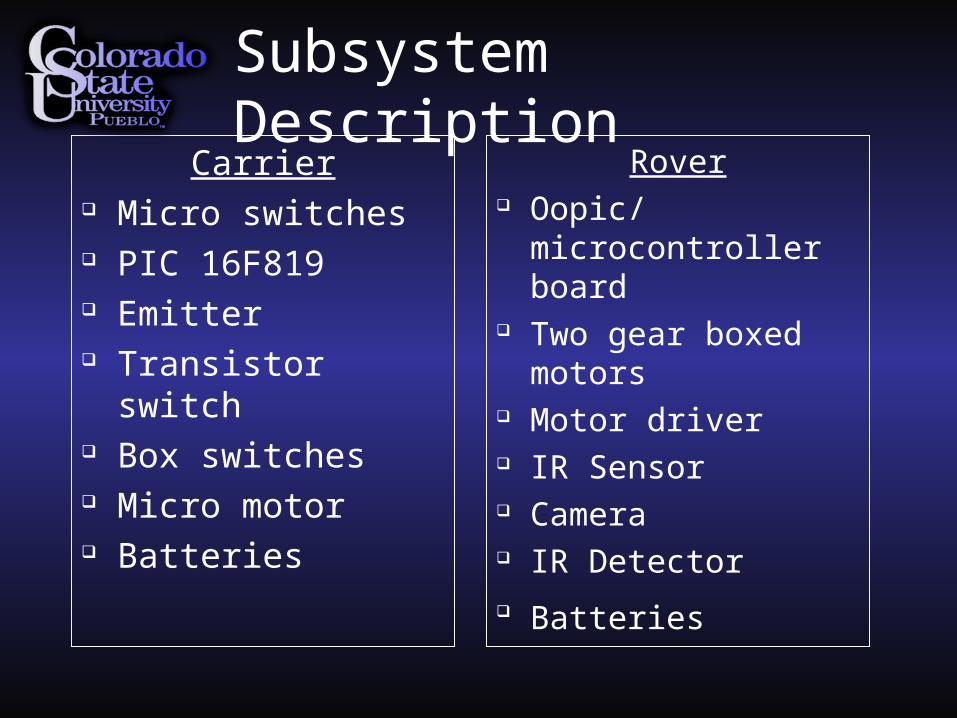
Subsystem DescriptionCarrier
Micro switches PIC 16F819 Emitter Transistor switch Box switches Micro motor Batteries
Rover Oopic/
microcontroller board Two gear boxed
motors Motor driver IR Sensor Camera IR Detector Batteries

Subsystem Description: Carrier
Micro switches – Sense landing. Must be pressed for a continuous 5 minutes.
PIC – Once 5 min has elapsed a signal is sent to turn on emitter.
Emitter – Emit IR signal to detector on Rover to turn it on.
Transistor switch – The base is being saturated allowing voltage to flow through it to the motor.
Box switches – Manual opening and closing. Micro motor – Opening/closing mechanism for
carrier. Batteries – 1-9v for PIC, 2-AA for motor.
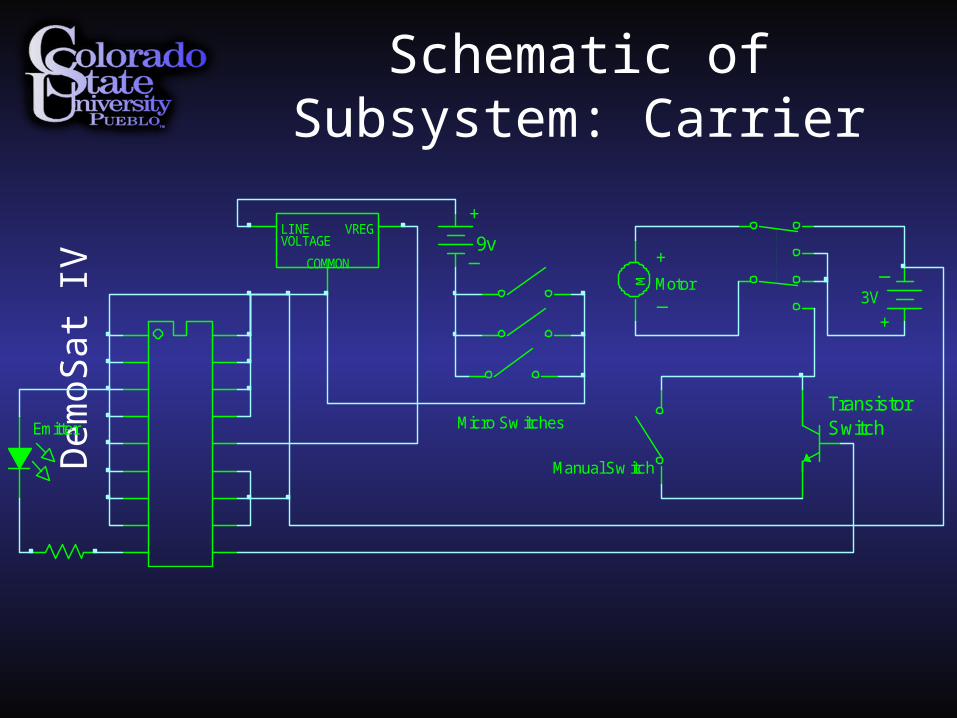
Schematic of Subsystem: Carrier
Dem
oSat
IV
Emitter
LINE VREG
COMMON
VOLTAGE 9v
Micro Sw itches
MotorM
Manual Sw itch
+
_
3V
_
+
+
_
TransistorSwitch

Subsystem Description: Rover
IR Detector – Sense emitter to turn Rover on. OOPic/ microcontroller board – Object oriented
with built in functionality to perform extensive electronic commands.
Gear boxed motors – 6 gear box motor. Motor driver – Takes a PWM signal and converts it
into speed and direction of 2 independent motors. IR sensor – Sense objects: avoid obstacle / picture. Camera – Take pictures of landing site. Batteries – 1-9v for OOPic, 4-AA for motor drivers.

OO
Pic
MD22Motordriver
Camera Relay Circuit
IR Detector
IR Scanner (Sharp GP2D12)
FlatFoto Digital Camera
3MP
Tamiya 6-Gearbox
Tamiya 6-Gearbox
Block Diagram of Subsystem: Rover
Dem
oSat
IV
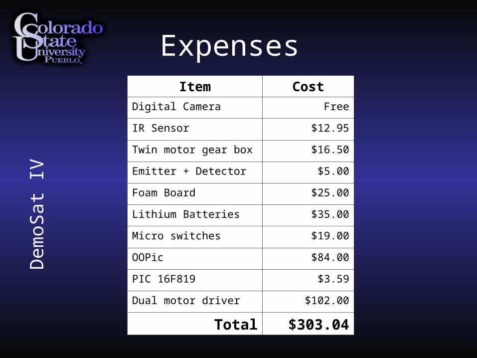
Item Cost
Digital Camera Free
IR Sensor $12.95
Twin motor gear box $16.50
Emitter + Detector $5.00
Foam Board $25.00
Lithium Batteries $35.00
Micro switches $19.00
OOPic $84.00
PIC 16F819 $3.59
Dual motor driver $102.00
Total $303.04
Expenses
D
emoS
at I
V

Mass Budget
D
emoS
at I
V
Carrier Rover
Rod 28.4g OOPic 42.9g
Foam padding 30.0g Motor controller 73.3g
Brackets 32.1g Camera 78.4g
Hinges 42.8g Frame 80.0g
HOBO 50.0g Motors 129.3g
Micro switches 62.4g Wheels 162.2g
Micro motor 62.8g Batteries 165.6g
Batteries 100.9g
Press pad 136.7g
Rat traps 141.2g
Cushion foam 210.8g
Misc 136g
Total 1034.1g Total 731.7g
Total: 1765.8g

Testing
• Carrier opening Micro motor with latch
• Rover traction Wheels with tracks and spikes
• Drag test Trash bag stayed in tact
• Drop test Rover stayed in place
• Cold test In Freezer for 1 ½ hours. No
Voltage loss.
Dem
oSat
IV

Full Function Test
D
emoS
at I
V

Project Organization
David – Rover circuitry and programming Erik – Mechanical design and implementation Anna – Carrier electronics and programming Matt – Carrier electronics + rover mechanics Augustine – Carrier opening design and
implementation.
Dem
oSat
IV

Top Related