


Languages
Pages
Legal

LABORATORY MANUAL
I. C. ENGINES &
GAS TURBINES (ME-317-F)
LIST OF EXPERIMENTS
S.No. Name of the Experiment Page From To
1. To study the constructional details & working principles of two-stroke petrol/ four-stroke petrol Engine.
1 4
2. To study the constructional details & working principles of two-stroke Diesel / four-stroke Diesel Engine.
5 8
3. Analysis of exhausts gases from single-cylinder/ multi-cylinder/ petrol engine by Orsat apparatus.
9 12
4. To prepare heat balance sheet on multi-cylinder diesel engine / petrol engine.
13 18
5. To find the indicated horse power (IHP) on multi-cylinder diesel engine / petrol engine by Morse test.
19 22
6. To prepare variable speed performance test of a multi-cylinder /single-cylinder petrol engine / diesel engine and prepare the curve (i) bhp, ihp, fhp Vs Speed (ii) Volumetric efficiency & indicated specific fuel consumption Vs Speed.
23 28
7. To find fhp of multi cylinder diesel engine / petrol engine by Willian’s Line Method & Motoring Method.
29 32
8. To perform constant speed performance test on a single-cylinder/ multi-cylinder diesel engine & draw curves of (i) bhp Vs fuel rate, air rate and A/F and (ii) bhp Vs mep, mechanical efficiency & s.f.c.
33 37
9. To study and determine the effect of A/F ratio on the performance of the two stroke, single – cylinder petrol engine.
38 42
10. To study and draw the valve timing diagram four stroke, single – cylinder diesel engine.
43 46
11. To draw the scavenging characteristic curves of single cylinder petrol engine.
12. To find intensity of smoke from a single cylinder / multi-cylinder diesel engine.
13. To measure CO & Hydrocarbons in the exhaust of 2- stroke / 4-stroke petrol engine.
Note:-
1) At least ten experiments are to be performed in the semester.
2) At least seven experiments should be performed from the above list. Remaining three experiments may either be performed from the above list or designed & set by the concerned institution as per the scope of the syllabus.

EXPERIMENT NO.1
Aim: -To Study the construction details & working principal of 2-Stroke / 4-
Stroke Petrol Engine. Apparatus: - Models of 2-Stroke / 4-Stroke Engines. Theory: - The working Principle of Engines.
• Four Stroke (S.I) Engine. In a four stroke engine, the cycles of operations is completed in 4 strokes of piston or 2 revolution of crank shaft. Each stroke consists of 180° & hence the fuel cycle consists of 720° of crank rotation. The 4-Strokes are: -
• Suction or Intake Stroke: - In starts at, when the piston is at top dead centre & about to move downwards. The inlet valve is open at that time and exhaust valve is closed due to suction created by the motion of the piston towards the bottom dead centre, the charge containing air fuel mixture is drawn into the cylinder. When the piston reaches BDC the suction stroke ends and inlet valve is closed.
• Compression Stroke: - The charge taken into the cylinder during suction stroke is compressed by return stroke of piston. During this stroke both the valves are closed. The mixture which fills the entire cylinder volume is now compressed into the clearance volume. At the end, the mixture is ignited with the help of electrode of spark plug. During the burning process the chemical energy of fuel is converted to heat energy. The pressure is increased in the end due to heat release.
• Expansion Stroke: - The burnt gases escape out and the exhaust valve opens but inlet valve remaining closed the piston moves from BDC to TDC and sweeps the burnt gases out at almost atmospheric pressure. The exhaust valve gets closed at the end of this stroke. Thus, for one complete cycle of engine, there is only one power stroke while crank shaft makes 2 revolutions.
• Exhaust Stroke: - During the upward motion of the piston, the exhaust valve is open and inlet valve is closed. The piston moves up in cylinder pushing out the burnt gases through the exhaust valve. As the piston reaches the TDC, again the inlet valve opens and fresh charge is taken in during next downward movement of the piston and the cycle is repeated.
2-Stroke (S.I) Engines.
In a 2-Stroke engine, the filling process is accompanied by the change compressed in a crank case or by a blower. The induction of compressed charge moves out the product of combustion through exhaust ports. Therefore, no piston stroke is required. For these 2-strokes one for compression of fresh charge and second for power stroke.
The charge conducted into the crank case through the spring loaded valve when the pressure in the crank case is reduced due to upward motion of piston during the compression stroke. After the compression & ignition expansion takes place in usual way.
During the expansion stroke the charge in crankcase is compressed. Near the end of the expansion stroke, the piston uncovers the exhaust ports and the cylinder pressure drops to atmosphere pressure as combustion produced leave the cylinder.
Construction Details • Cylinder: - It is a cylindrical vessel or space in which the piston makes a
reciprocating produces. • Piston: - It is a cylindrical component fitted into the cylinder forming the
moving boundary of combustion system. It fits in cylinder perfectly. • Combustion Chamber: - It is the space enclosed in the upper part of
cylinder, by the cylinder head & the piston top during combustion process. • Inlet Manifold: - The pipe which connects the intake system to the inlet
valve of engine. • Exhaust Manifold: - The pipe which connects the exhaust system to the
exhaust valve of engine. • Inlet / Exhaust Valves: - They are provided on the cylinder head to head to
regulate the charge coming into or going out of the chamber. • Spark Plug: - It is used to initiate the combustion process in S.I engines. • Connected Rod: - It connects piston & the crank shaft. • Crank shaft: - It converts the reciprocating motion of the piston into useful
rotary motion of output shaft. • Gudgeon pins: - It forms a link between connection rod and the piston. • Cam shaft: - It controls the opening & closing of the valves. • Cam: - They open the valves at the correct tunes. • Carburetor: - Used in S.I engine for atomizing & vaporizing and mixture it
with air in varying proportion. Viva Questions
1. Describe the working principle of 2-Stroke petrol Engine? 2. Describe the working principle of 4-Stroke petrol Engine? 3. What is Suction Stroke? 4. What is compression Stroke? 5. Describe Expansion / Power Stroke?
6. Describe Exhaust Stroke? 7. What are the construction details of a four stroke petrol Engine? 8. What is the main deference in 2-Stroke Petrol Engine and 4-Stroke Petrol Engine?
EXPERIMENT NO.2 Aim: - To study the constructional details & working principles involved in a
2-Stroke & 4-Stroke Diesel Engines. Apparatus: - Model of 2-Stroke / 4-Stroke Diesel Engine. Theory: -
• Four Stroke (C.I.) Engine. In four strokes C.I. Engine compression ratio is from 16 to 20. During suction stroke air is inducted. In C.I. engines high pressure. Fuel pump and injectors are provided to inject the fuel into combustion chamber and ignition chamber system is not necessary.
Construction Details
1. Suction: - During suction stroke, air is inducted through inlet valve. 2. Compression: - The air inducted is compressed into the clearance volume. 3. Expansion: - Fuel injection starts nearly at the end of the compression
stroke. The rate of injection is such that the combustion maintains the pressure constant inspired of piston movement on its expansion stroke increasing the volume. After injection of fuel, the products of combustion chamber expand.
4. Exhaust: - The piston traveling from BQC to TDC pushes out the products of combustion out of cylinder.
• Two Stroke (C.I.) Engine. In two stroke engines, the cycle is completed in one revolution of the crankshaft. In 2-stroke engine, the filling process is accomplished by the charge compressed in crankcase or by a blower. The induction of compressed charge moves out of the exhaust ports. Therefore, no piston strokes are required for these 2 operations. Two strokes are sufficient to complete the cycle one for compressing the fresh charge and other for expansion or power stroke.

1. Compression: - The air or charge is inducted into the crankcase through the spring loaded inlet valve when the pressure in crankcase is reduced due to upward motion of piston.
2. Expansion: - During this, the charge in the crankcase is compressed. At the end the piston uncovers the exhaust ports and cylinder pressure drops to the atmospheric pressure. Further movement of piston opens the transfer ports, permitting the slightest compressed charge in the crankcase to enter the engine cylinder.
Construction Details
1. Cylinder: - In it the piston makes a reciprocating process motion. 2. Piston: - It is a cylindrical component fitted into the cylinder forming
the moving boundary of the combustion system. It fits into cylinder. 3. Combustion Chamber: - The space enclosed in the upper part of the
cylinder, by the head and the piston top during the combustion process. 4. Inlet/ Outlet ports: - They are provided on the side of cylinder to
regulate the charge coming in and out of cylinder. 5. Fuel Injector: - It injects the fuel in combustion chamber to initiate
combustion process for power stroke. 6. Connecting Rod: - It interconnects crank shaft and the piston. 7. Fly Wheel: - The net torque imparted to the crankshaft during one
complete cycle of operation of the engine fluctuates cow sing change in angular velocity of shaft. In order to achiever uniform torque an internal mass is attached to the output shaft & this is called as fly wheel.
Viva Questions
1. Describe the working principle of 2-Stroke Diesel Engine? 2. Describe the working principle of 4-Stroke Diesel Engine? 3. What is compression Stroke? 4. Describe Expansion / Power Stroke? 5. What are the construction details of a four stroke Diesel Engine? 6. What is the main deference in 2-Stroke Diesel Engine and 4-Stroke Diesel
Engine? 7. Describe the deference in 2-stroke Diesel Engine & 2-Stroke Petrol Engine?
EXPERIMENT No. 3 AIM:- Analysis of exhaust gases from Two-Stroke single-cylinder petrol engine
by Orsat Apparatus. APPARATUS USED:- Orsat apparatus, caustic potash solution, alkaline solution of pyrogallic acid, cuprous chloride solution, brine and dry
flue gas sample.
THEORY:-
To check the combustion efficiency of I. C. engines, it is essential to know the
constituents of the flue gases being exhausted. The various constituents the flue
gases are CO2, excess O2, CO, SO2, and N2.The volumetric analysis of mainly CO2,
O2, and CO is required, because the heat released is sufficiently large when carbon
of the fuel burns to rather than when it burns to CO, secondly to determine the
requisite amount of oxygen for proper burning of fuel. Such an analysis can be
carried out conveniently with the help of Orsat apparatus.
An Orsat apparatus is shown in figure. It consists of three flasks to absorb different
gases. Flask no. 1 contains caustic potash solution and this absorbs CO2 present in
the flue gas. Similarly flask no. 2 and 3 contains alkaline solution of pyrogallic
acid, and cuprous chloride solution to absorb O2, and CO respectively.
100 ml of a dry flue gas sample is sucked in the eudiometer tube of the apparatus
and is allowed to react with the three solutions turn by turn. The amount of CO2,
O2, and CO absorbed in the respective solution is estimated from the eudiometer
scale.

PROCEDURE:-
1. Fill 2/3 of the aspirator bottle with the brine solution. 2. Fill three flasks i.e. flask no. 1, 2,and 3 with the required quantity of the
caustic potash solution, alkaline solution of pyrogallic acid, and cuprous chloride solution respectively and close their valves.
3. Open the valve of flask no. 1, now by operating the rubber bladder and
opening the three way cock to the atmosphere, bring the level of caustic potash solution to the mark A. close the valve of flask no. 1.
4. Repeat as step 3, to bring the level of alkaline solution of pyrogallic acid, and cuprous chloride solution to their respective marks B and C. Close the valves of flask no. 2 and 3.
5. Open the three-way cock to the atmosphere and raise the aspirator bottle so that air present in the Eudiometer is expelled to atmosphere. Close the three way cock and lower the aspirator bottle to read zero on eudiometer scale. The eudiometer is ready to receive 100 ml of gas sample.
6. Open the three-way cock and allow the flue gas sample to enter the eudiometer. Close the three-way cock, now 100 ml of gas has entered the apparatus. Open the three-way cock to the atmosphere and raise the aspirator bottle so that whole gas present in the eudiometer is expelled to atmosphere. Repeat this step twice or thrice so that 100 ml of representative flue gas sample remain in the apparatus. Close the three way cock finally.
7. Now open the valve of flask no. 1. Raise and lower the aspirator bottle few times so that gas is passed-in and out of flask several times. Lower the aspirator bottle and bring the level of caustic potash solution again to mark A. Close the valve of flask. Bring the aspirator bottle near the eudiometer and position it so that, the liquid level in the both is same. Note the liquid level on the scale. This gives the %age of CO2 present in the flue gas sample.
8. Repeat the procedure as step 7 to determine the %age of O2, and CO
respectively by passing the remaining sample through the two flasks.
OBSERVATIONS:- Amount of flue gas after absorption by caustic potash solution = X ml Amount of flue gas after absorption by alkaline solution of pyrogallic acid = Y ml Amount of flue gas after absorption by cuprous chloride solution = Z ml CALCULATIONS:- (i) Amount of flue gas sample = 100 ml (ii) Amount of CO2 = ( 100 - X ) ml (iii) Amount of O2 = ( X –Y ) ml (iv) Amount of CO = ( Y + Z ) ml (v) Amount of N2 = ( 100 – Z ) ml PRECAUTIONS:-
1. The apparatus should be air tight.
2. The eudiometer tube of the apparatus should be well flushed with the flue
gas sample before performing the experiment.
3. The brine solution in the aspirator bottle should be saturated, as it may
absorb some constituents of the gas sample and thereby cause errors.
RESULTS:- Performance curves are plotted and they are similar to the standard
performance Curves. Viva Question
1. What is the working of orsat apparatus ?
2. What is the purpose of orsat apparatus ?
3. Which solution is mainly used in orsat Appratus?
4. Define the brine and dry flue gas?

EXPERIMENT No. 4
AIM:- To prepare heat balance sheet on Single-Cylinder Diesel Engine.
APPARATUS USED :- Single-Cylinder Diesel Engine (Constant Speed) Test
Rig, Stop Watch and Digital Tachometer.
THEORY:-
The thermal energy produced by the combustion of fuel in an engine
is not completely utilized for the production of the mechanical power. The thermal
efficiency of I. C. Engines is about 33 %. Of the available heat energy in the fuel,
about 1/3 is lost through the exhaust system, and 1/3 is absorbed and dissipated by
the cooling system.
It is the purpose of heat balance sheet to know the heat energy distribution, that is,
how and where the input energy from the fuel is is distributed.
The heat balance sheet of an I. C. Engine includes the following heat distributions:
a. Heat energy available from the fuel brunt.
b. Heat energy equivalent to output brake power.
c. Heat energy lost to engine cooling water.
d. Heat energy carried away by the exhaust gases.
e. Unaccounted heat energy loss.
FORMULE USED :-
(i) Torque, T = 9.81 x W x R Effective N-m.
; Where R Effective = (D + d)/2 or (D + tBelt)/2 m, and
W (Load) = ( S1 - S2 ) Kg,
(ii) Brake Power, B P = ( 2πN T ) / 60, 000 KW
; Where N = rpm, T = Torque N-m,
(iii) Fuel Consumption, m f = ( 50 ml x 10 -6 x ρ Fuel ) / ( t )
Kg/Sec

Here; 1 ml = 10-3 liters, and 1000 liters = 1 m3
So 1 ml = 10-6 m3
(iv) Heat energy available from the fuel brunt, Qs = mf x C. V. x 3600 KJ/hr
(v) Heat energy equivalent to output brake power, QBP = BP x 3600 KJ/hr
(vi) Heat energy lost to engine cooling water, QCW = mw x Cw (two - twi) x 3600
KJ/hr
(vii) Heat energy carried away by the exhaust gases, QEG = mfg x Cfg (tfg – tair) x
3600 KJ/hr
; Where mfg = (mf + mAir) Kg/Sec, and mAir = Cd Ao √2 g Δh ρ Air ρ Water
Kg/ Sec
; Where Cd ( Co-efficient of Discharge ) = 0.6, ρ Air = ( Pa x 102 ) / ( R x Ta )
Kg/ m3,
Ao ( Area of Orifice ) = (π do2)/ 4 m2, P1 = 1.01325 Bar, R = 0.287
KJ/Kg . K,
Ta = ( ta + 273 ) K, ta = Ambient Temperature OC
(viii) Unaccounted heat energy loss, QUnaccounted = Qs – { QBP + QCW + QEG }
KJ/hr
PROCEDURE :-
1. Before starting the engine check the fuel supply, lubrication oil, and availability
of cooling water.
2. Set the dynamometer to zero load and run the engine till it attain the working
temperature and steady state condition.
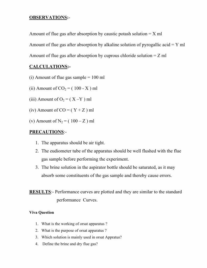
3. Note down the fuel consumption rate, Engine cooling water flow rate, inlet and
outlet temperature of the engine cooling water, Exhaust gases cooling water
flow rate, Air flow rate, and Air inlet temperature.
4. Set the dynamometer to 20 % of the full load, till it attains the steady state
condition. Note down the fuel consumption rate, Engine cooling water flow
rate, inlet and outlet temperature of the engine cooling water, Exhaust gases
cooling water flow rate, Air flow rate, and Air inlet temperature.
5. Repeat the experiment at 40 %, 60 %, and 80 % of the full load at constant
speed.
6. Disengage the dynamometer and stop the engine.
7. Do the necessary calculation and prepare the heat balance sheet.
OBSERVATIONS:-
Engine Speed, N = 1500 rpm
No. of Cylinders, n = Single
Calorific Value of Fuel, C.V. = 38,000 KJ/Kg
Specific Heat of Water, Cw = 4.187 KJ/Kg . K
Specific Heat of Exhaust Flue Gases, Cfg = 2.1 KJ/Kg . K
Gas Constant, R = 0.287 KJ/Kg . K
Ambient Temperature, ta = oC
Atmospheric Pressure, Pa = 1.01325 Bar
Orifice Diameter, do = 25 x 10-3 m
Co-efficient of Discharge, Cd = 0.6
Density of fuel (Diesel), ρ Fuel = 810 to 910 Kg/m3
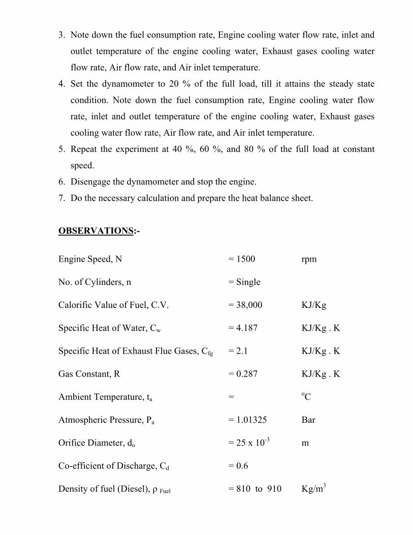
Density of Water, ρwater = 1,000 Kg/m3
Brake Drum Diameter, D = 181.5 x 10⁻³ m
Rope Diameter, d = m
Or Belt thickness, tBelt = 5.5 x 10⁻³ m
OBSERVATIONS TABLE :-
Sl.
No
.
Engine
Speed,
N (rpm)
Dynamometer Spring
Balance Readings, (Kg)
Time
taken for
50 ml
fuel, t
(Sec.)
Engine
Cooling
Water
Flow Rate,
mw (Kg/hr)
Engine Cooling Water
Temperatures, (o C)
Exhaust Gas
Temperature,
tfg (o C)
Manometer
Reading,
∆h (m) S1 (Kg) S2 (Kg) twi (o C) two (o C)
1.
1500
2.
1500
3.
1500
4.
1500
CALCULATIONS:-
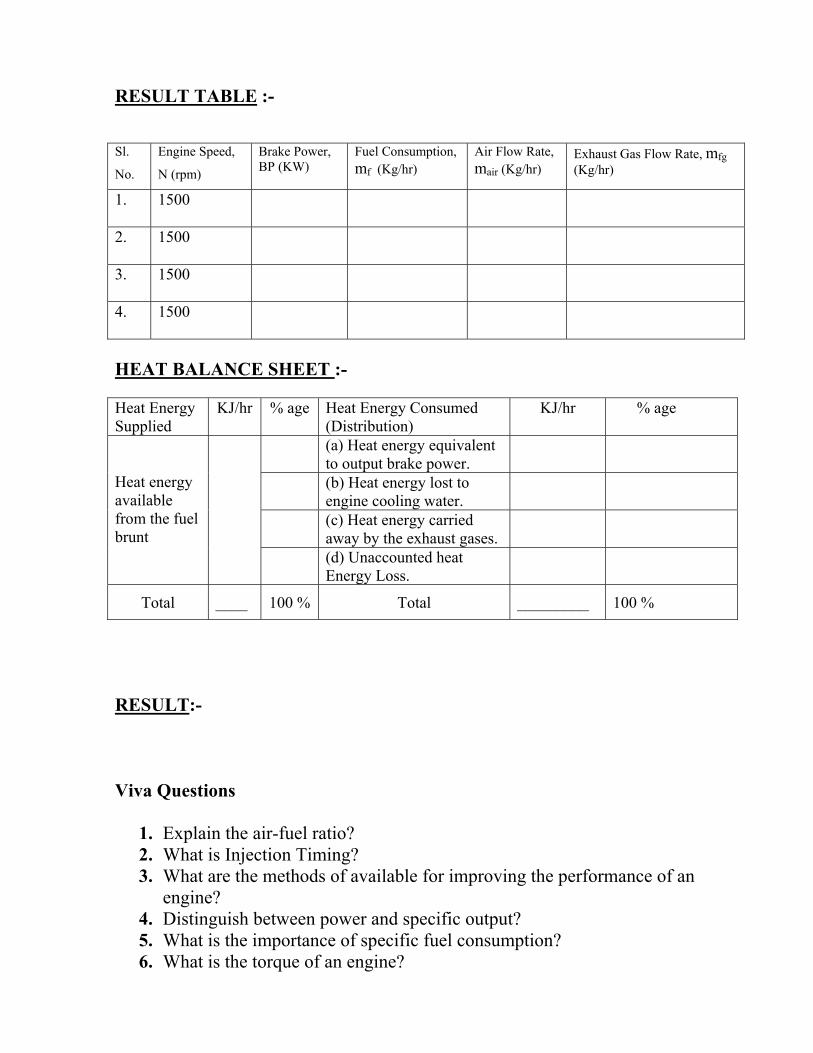
RESULT TABLE :- Sl.
No.
Engine Speed,
N (rpm)
Brake Power, BP (KW)
Fuel Consumption, mf (Kg/hr)
Air Flow Rate, mair (Kg/hr)
Exhaust Gas Flow Rate, mfg (Kg/hr)
1. 1500
2. 1500
3. 1500
4. 1500
HEAT BALANCE SHEET :- Heat Energy Supplied
KJ/hr % age Heat Energy Consumed (Distribution)
KJ/hr % age
Heat energy available from the fuel brunt
(a) Heat energy equivalent to output brake power.
(b) Heat energy lost to engine cooling water.
(c) Heat energy carried away by the exhaust gases.
(d) Unaccounted heat Energy Loss.
Total ____ 100 % Total _________ 100 %
RESULT:- Viva Questions
1. Explain the air-fuel ratio? 2. What is Injection Timing? 3. What are the methods of available for improving the performance of an
engine? 4. Distinguish between power and specific output? 5. What is the importance of specific fuel consumption? 6. What is the torque of an engine?
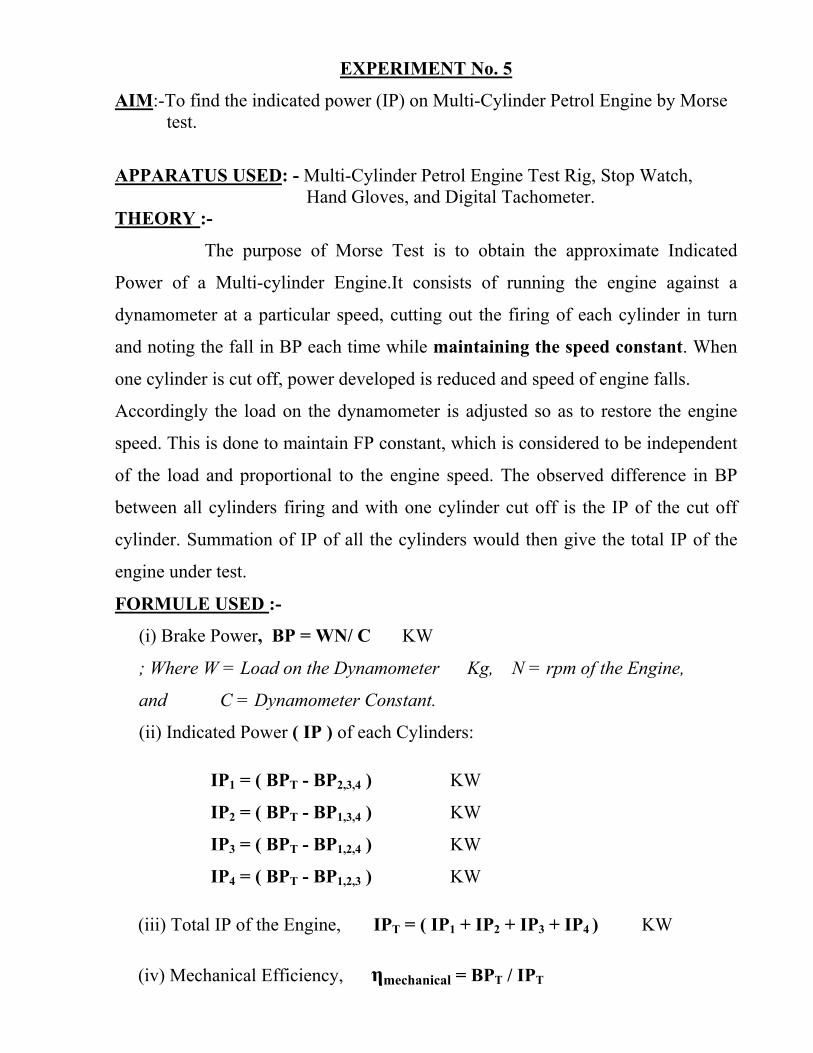
EXPERIMENT No. 5
AIM:-To find the indicated power (IP) on Multi-Cylinder Petrol Engine by Morse test.
APPARATUS USED: - Multi-Cylinder Petrol Engine Test Rig, Stop Watch, Hand Gloves, and Digital Tachometer.
THEORY :-
The purpose of Morse Test is to obtain the approximate Indicated
Power of a Multi-cylinder Engine.It consists of running the engine against a
dynamometer at a particular speed, cutting out the firing of each cylinder in turn
and noting the fall in BP each time while maintaining the speed constant. When
one cylinder is cut off, power developed is reduced and speed of engine falls.
Accordingly the load on the dynamometer is adjusted so as to restore the engine
speed. This is done to maintain FP constant, which is considered to be independent
of the load and proportional to the engine speed. The observed difference in BP
between all cylinders firing and with one cylinder cut off is the IP of the cut off
cylinder. Summation of IP of all the cylinders would then give the total IP of the
engine under test.
FORMULE USED :-
(i) Brake Power, BP = WN/ C KW
; Where W = Load on the Dynamometer Kg, N = rpm of the Engine,
and C = Dynamometer Constant.
(ii) Indicated Power ( IP ) of each Cylinders:
IP1 = ( BPT - BP2,3,4 ) KW
IP2 = ( BPT - BP1,3,4 ) KW
IP3 = ( BPT - BP1,2,4 ) KW
IP4 = ( BPT - BP1,2,3 ) KW
(iii) Total IP of the Engine, IPT = ( IP1 + IP2 + IP3 + IP4 ) KW
(iv) Mechanical Efficiency, ηmechanical = BPT / IPT
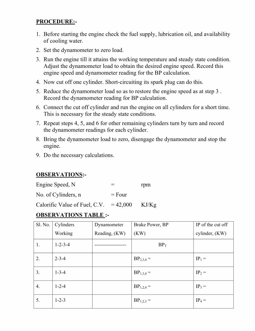
PROCEDURE:-
1. Before starting the engine check the fuel supply, lubrication oil, and availability of cooling water.
2. Set the dynamometer to zero load. 3. Run the engine till it attains the working temperature and steady state condition.
Adjust the dynamometer load to obtain the desired engine speed. Record this engine speed and dynamometer reading for the BP calculation.
4. Now cut off one cylinder. Short-circuiting its spark plug can do this. 5. Reduce the dynamometer load so as to restore the engine speed as at step 3 .
Record the dynamometer reading for BP calculation. 6. Connect the cut off cylinder and run the engine on all cylinders for a short time.
This is necessary for the steady state conditions. 7. Repeat steps 4, 5, and 6 for other remaining cylinders turn by turn and record
the dynamometer readings for each cylinder. 8. Bring the dynamometer load to zero, disengage the dynamometer and stop the
engine. 9. Do the necessary calculations.
OBSERVATIONS:-
Engine Speed, N = rpm
No. of Cylinders, n = Four
Calorific Value of Fuel, C.V. = 42,000 KJ/Kg
OBSERVATIONS TABLE :- Sl. No. Cylinders
Working
Dynamometer
Reading, (KW)
Brake Power, BP
(KW)
IP of the cut off
cylinder, (KW)
1. 1-2-3-4 ------------------- BPT
2. 2-3-4 BP2,3,4 = IP1 =
3. 1-3-4 BP1,3,4 = IP2 =
4. 1-2-4 BP1,2,4 = IP3 =
5. 1-2-3 BP1,2,3 = IP4 =
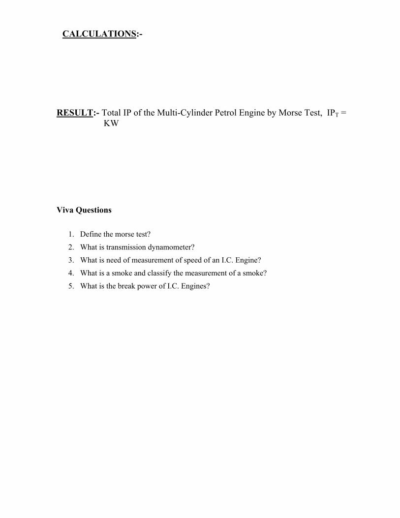
CALCULATIONS:-
RESULT:- Total IP of the Multi-Cylinder Petrol Engine by Morse Test, IPT = KW
Viva Questions
1. Define the morse test?
2. What is transmission dynamometer?
3. What is need of measurement of speed of an I.C. Engine?
4. What is a smoke and classify the measurement of a smoke?
5. What is the break power of I.C. Engines?

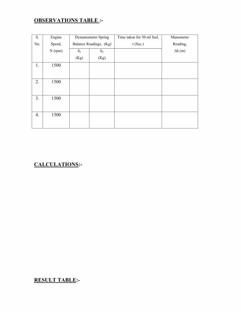
EXPERIMENT No. 6 AIM:- To prepare variable speed performances test on a Two-Stroke, Single-
Cylinder Petrol Engine and prepare the curves: (i) BP, BSFC, BMEP, Torque Vs Speed and (ii) Volumetric Efficiency & A/F Ratio Vs Speed.
APPARATUS USED :- Two-Stroke, Single-Cylinder Petrol Engine Test Rig, Stop Watch, and Digital Tachometer.
THEORY :-
S.I. Engines are often used for automotive purposes. It is important
to know the torque, brake mean effective pressure, and specific fuel consumption
over the engine working speed range. For this purpose variable speed test at full
load and part load is conducted.To test the park ignition engine at full load the
throttle valve is kept wide open and the brake load is adjusted to obtain the lowest
desired speed. The ignition timing may be set to obtain maximum output at this
speed. Rate of fuel consumption, dynamometer load reading and speed are
recorded.
FORMULE USED:-
(i) Torque, T = 9.81 x W x R Effective N-m.
; Where R Effective = (D + d)/2 m, and W (Load) = ( S1 - S2 ) Kg,
(ii) Brake Power, B P = ( 2πN T ) / 60, 000 KW
; Where N = rpm, T = Torque N-m,
(iii) Indicated Power, I P = n ( Pm x L Stroke x A x N’) / 60,000 KW
; Where Pm = Mean Effective Pressure N/ m2,
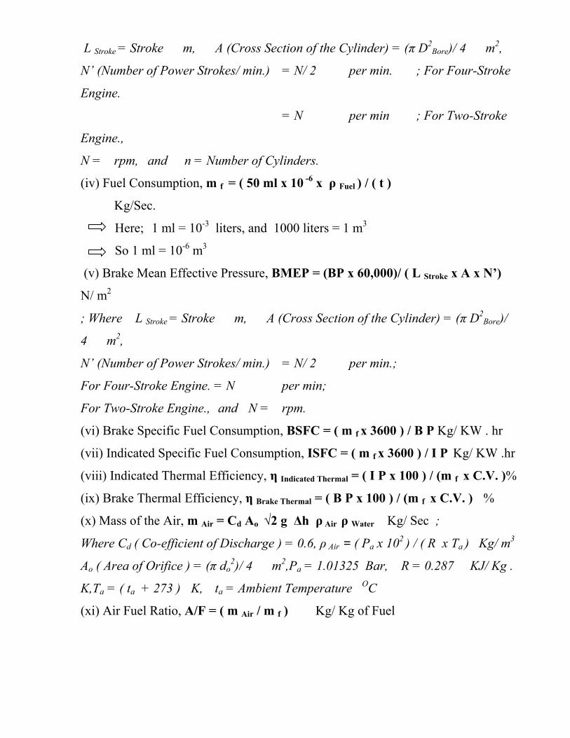
L Stroke = Stroke m, A (Cross Section of the Cylinder) = (π D2Bore)/ 4 m2,
N’ (Number of Power Strokes/ min.) = N/ 2 per min. ; For Four-Stroke
Engine.
= N per min ; For Two-Stroke
Engine.,
N = rpm, and n = Number of Cylinders.
(iv) Fuel Consumption, m f = ( 50 ml x 10 -6 x ρ Fuel ) / ( t )
Kg/Sec.
Here; 1 ml = 10-3 liters, and 1000 liters = 1 m3
So 1 ml = 10-6 m3
(v) Brake Mean Effective Pressure, BMEP = (BP x 60,000)/ ( L Stroke x A x N’)
N/ m2
; Where L Stroke = Stroke m, A (Cross Section of the Cylinder) = (π D2Bore)/
4 m2,
N’ (Number of Power Strokes/ min.) = N/ 2 per min.;
For Four-Stroke Engine. = N per min;
For Two-Stroke Engine., and N = rpm.
(vi) Brake Specific Fuel Consumption, BSFC = ( m f x 3600 ) / B P Kg/ KW . hr
(vii) Indicated Specific Fuel Consumption, ISFC = ( m f x 3600 ) / I P Kg/ KW .hr
(viii) Indicated Thermal Efficiency, η Indicated Thermal = ( I P x 100 ) / (m f x C.V. )%
(ix) Brake Thermal Efficiency, η Brake Thermal = ( B P x 100 ) / (m f x C.V. ) %
(x) Mass of the Air, m Air = Cd Ao √2 g Δh ρ Air ρ Water Kg/ Sec ;
Where Cd ( Co-efficient of Discharge ) = 0.6, ρ Air = ( Pa x 102 ) / ( R x Ta ) Kg/ m3
Ao ( Area of Orifice ) = (π do2)/ 4 m2,Pa = 1.01325 Bar, R = 0.287 KJ/ Kg .
K,Ta = ( ta + 273 ) K, ta = Ambient Temperature OC
(xi) Air Fuel Ratio, A/F = ( m Air / m f ) Kg/ Kg of Fuel

(xii) Volumetric Efficiency, η Volumetric = ( VAir x 100 )/ Vs %
; Where VAir ( Volume of air inhaled/ Sec.) = ( m Air / ρ Air ) m3/ Sec.
Vs ( Swept Volume/ Sec.) = n . ( L Stroke . A.. N’ )/ 60 m3/ Sec.,
And Volume of fuel is Neglected (Based on free air conditions),
L Stroke = Stroke m, A (Cross Section of the Cylinder) = (π D2Bore)/ 4 m2,
N’ (Number of Power Strokes/ min.) = N/ 2 per min. ;
For Four-Stroke Engine.
= N per min ;
For Two-Stroke Engine.,
N = rpm., and n = Number of Cylinders.
(xiii) Mechanical Efficiency, ηmechanical = BP / IP
PROCEDURE:-
1. Before starting the engine check the fuel supply, lubrication oil.
2. Set the dynamometer to zero load.
3. Run the engine till it attains the working temperature and steady state condition.
4. Adjust the dynamometer load to obtain the desired engine speed. Note down the fuel consumption rate.
5. Adjust the dynamometer to the new value of the desired speed. Note and record the data as in step 4.
6. Repeat the experiment for various speeds upto the rated speed of the engine.
7. Do the necessary calculations.

OBSERVATIONS:-
No. of Cylinders, n = Single
Brake Drum Diameter, D = 156 x 10-3 m
Rope Diameter, d = 18 x 10-3 m
Bore, DBore = 56.5 X 10⁻³ m
Stroke, LStroke = 58.04 x 10⁻³ m
Engine Displacement, V Swept = 145.45 x 10⁻⁶ m3
Engine Horse Power, BHP = 7.48 BHP at 5500 rpm.
Density of fuel (Petrol), ρ Fuel = 720 to 790 Kg/ m3
Density of Manometer fluid, ρ Water = 1,000 Kg/ m3
Calorific value of fuel (Petrol), C.V. = 42000 KJ/ Kg
Orifice Diameter, do = 25 x 10-3 m
Co-efficient of Discharge, Cd = 0.6
Ambient Temperature, ta = K
Atmospheric Pressure, Pa = 1.01325 Bar
OBSERVATIONS TABLE :- Sl. No. Engine Speed,
N (rpm)
Dynamometer Spring Balance
Readings, (Kg)
Time taken for 50
ml fuel,
t (Sec.)
Manometer
Reading,
∆h (m) S1 (Kg) S2 (Kg)
CALCULATIONS:-
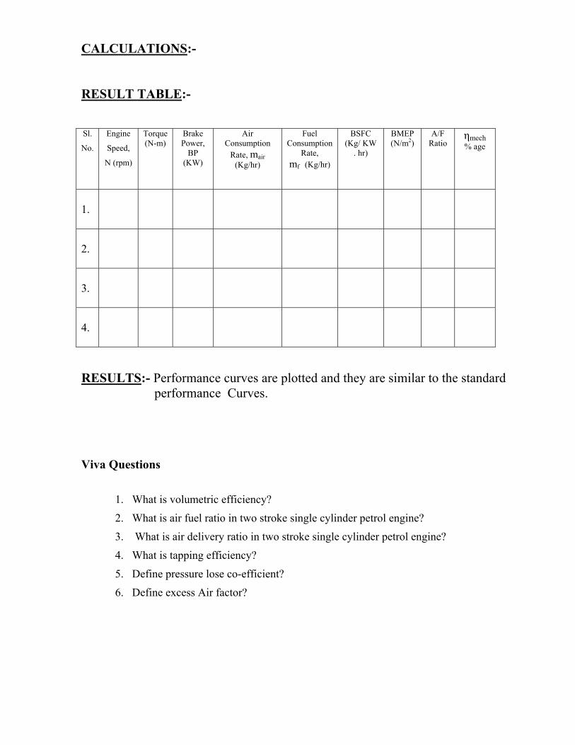
RESULT TABLE:- Sl.
No.
Engine
Speed,
N (rpm)
Torque (N-m)
Brake Power,
BP (KW)
Air Consumption
Rate, mair (Kg/hr)
Fuel Consumption
Rate, mf (Kg/hr)
BSFC (Kg/ KW
. hr)
BMEP (N/m2)
A/F Ratio
ηmech % age
1.
2.
3.
4.
RESULTS:- Performance curves are plotted and they are similar to the standard performance Curves.
Viva Questions
1. What is volumetric efficiency?
2. What is air fuel ratio in two stroke single cylinder petrol engine?
3. What is air delivery ratio in two stroke single cylinder petrol engine?
4. What is tapping efficiency?
5. Define pressure lose co-efficient?
6. Define excess Air factor?

EXPERIMENT No. 7
AIM:- To determine Frictional Power of Four-Stroke , Single Cylinder Diesel
(Constant Speed) Engine by Willian’s Line Method.
APPARATUS USED :- Four-Stroke , Single Cylinder Diesel (Constant Speed)
Engine Test Rig, Stop Watch, and Digital Tachometer.
THEORY:-
A curve between the fuel consumption rate and the Brake Power is
called the Willain’s Line. This method is used for determining the FP of the Diesel
Engine, which is assumed to be independent of the load at constant speed. In this
method, fuel consumption rate is measured for various loads at constant speed. The
load on the engine is varies with the help of dynamometer and corresponding to
each setting BP is calculated. Then a graph is drawn of fuel consumption rate
against the BP, and is extended back to cut the BP axis. The negative BP then
corresponds to the FP at a particular speed. This method is also enables to
determine IP without the use of an indicator.
FORMULE USED :-
(i) Torque, T = 9.81 x W x R Effective N-m.
; Where R Effective = (D + d)/2 or (D + tBelt)/2 m, and W (Load) = ( S1 - S2 ) Kg,
(ii) Brake Power, B P = ( 2πN T ) / 60, 000 KW
; Where N = rpm, T = Torque N-m,
(iii) Fuel Consumption, m f = ( 50 ml x 10 -6 x ρ Fuel ) / ( t ) Kg/Sec.
Here; 1 ml = 10-3 liters, and 1000 liters = 1 m3
So, 1 ml = 10-6 m3
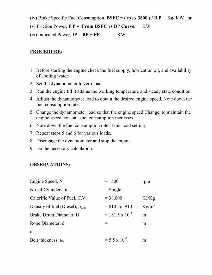
(iv) Brake Specific Fuel Consumption, BSFC = ( m f x 3600 ) / B P Kg/ KW . hr
(v) Friction Power, F P = From BSFC vs BP Curve. KW
(vi) Indicated Power, IP = BP + FP KW
PROCEDURE:-
1. Before starting the engine check the fuel supply, lubrication oil, and availability of cooling water.
2. Set the dynamometer to zero load. 3. Run the engine till it attains the working temperature and steady state condition. 4. Adjust the dynamometer load to obtain the desired engine speed. Note down the
fuel consumption rate. 5. Change the dynamometer load so that the engine speed Change, to maintain the
engine speed constant fuel consumption increases. 6. Note down the fuel consumption rate at this load setting. 7. Repeat steps 5 and 6 for various loads. 8. Disengage the dynamometer and stop the engine. 9. Do the necessary calculation.
OBSERVATIONS:-
Engine Speed, N = 1500 rpm
No. of Cylinders, n = Single
Calorific Value of Fuel, C.V. = 38,000 KJ/Kg
Density of fuel (Diesel), ρfuel = 810 to 910 Kg/m3
Brake Drum Diameter, D = 181.5 x 10⁻³ m
Rope Diameter, d = m
or
Belt thickness, tBelt = 5.5 x 10⁻³ m

OBSERVATIONS TABLE :- Sl. No. Engine Speed, N (rpm) Dynamometer Spring Balance Readings, (Kg) Time taken for 50 ml
fuel, t (Sec.) S1 (Kg) S2 (Kg)
1.
1500
2.
1500
3.
1500
4.
1500
CALCULATIONS:-
RESULT TABLE:- Sl. No. Engine Speed,
N (rpm)
Brake Power, BP (KW)
Fuel Consumption, mf (Kg/Sec)
Brake Specific Fuel Consumption, BSFC (Kg/ KW . hr)
1. 1500 2. 1500 3. 1500 4. 1500
RESULT:- Performance curves are plotted and they are similar to the standard
performance Curves and FP is calculated By Willian’s line Method.
Viva Questions
1. What is fan dynamometer?
2. Explain an automatic fuel flow meter?
3. Explain the method of measurement of smoke by comparison method?
4. Define the friction power?
5. Define Willian’s lines methods?

EXPERIMENT No. 8
AIM:- To perform constant speed performance test on a Four-Stroke Single-Cylinder Diesel Engine & Draw curves of (i) BP vs Fuel Rate, Air Rate and A/F ratio and (ii) BP vs BMEP, Mechanical Efficiency & BSFC.
APPARATUS USED: - Four-Stroke , Single-Cylinder (Constant Speed) Diesel
Engine Test Rig, Stop Watch, and Digital Tachometer.
THEORY:-
Under some circumstances (i.e Electric Generator) C. I. Engines are
required to run at constant speed. For this purpose the test is to be performed at
constant speed and the load is varied from zero to maximum. When load on the
engine increases its speed decreases. Accordingly the fuel supply is adjusted to
keep the engine speed constant. Corresponding to each load setting, dynamometer
readings and fuel consumption rate are measured. The BP, BSFC, BMEP, A/F,
and Mechanical Efficiency are calculated from measured data and plotted against
the load.
FORMULE USED:-
(i) Torque, T = 9.81 x W x R Effective N-m.
Where R Effective = (D + d)/ 2 or (D + tBelt)/ 2 m, and W (Load) = ( S1 - S2 )Kg,
(ii) Brake Power, B P = ( 2πN T ) / 60, 000 KW
; Where N = rpm, T = Torque N-m,
(iii) Fuel Consumption, m f = ( 50 ml x 10 -6 x ρ Fuel ) / ( t )
Kg/Sec.
Here; 1 ml = 10-3 liters, and 1000 liters = 1 m3
So, 1 ml = 10-6 m3

(iv) Brake Mean Effective Pressure, BMEP = (BP x 60,000)/ ( L Stroke x A x N’)
N/ m2
; Where L Stroke = Stroke m, A (Cross Section of the Cylinder) = (π D2Bore)/
4 m2,
N’ (Number of Power Strokes/ min.) = N/ 2 per min. ; For Four-Stroke
Engine.= N per min; For Two-Stroke Engine., and N = rpm.
(v) Brake Specific Fuel Consumption, BSFC = ( m f x 3600 ) / B P Kg/ KW . hr
(vi) Mass of the Air, m Air = Cd Ao √2 g Δh ρ Air ρ Water Kg/ Sec
; Where Cd ( Co-efficient of Discharge ) = 0.6, ρ Air = ( Pa x 102 ) / ( R x Ta )
Kg/ m3 Ao ( Area of Orifice ) = (π do2)/ 4 m2, Pa = 1.01325 Bar, R =
0.287 KJ/Kg . K, Ta = ( ta + 273 ) K, ta = Ambient Temperature OC
(vii) Air Fuel Ratio, A/F = ( m Air / m f ) Kg/ Kg of Fuel
(viii) Mechanical Efficiency, η mechanical = BP / IP
PROCEDURE:-
1. Before starting the engine check the fuel supply, lubrication oil, and availability of cooling water.
2. Set the dynamometer to zero load. 3. Run the engine till it attains the working temperature and steady state
condition. 4. Adjust the dynamometer load to obtain the desired engine speed. Note down
the fuel consumption rate. 5. Change the dynamometer load so that the engine speed Change, to maintain
the engine speed constant fuel consumption increases. 6. Note down the fuel consumption rate, speed, air inlet temperature, at this
load setting. 7. Repeat steps 5 and 6 for various loads. 8. Disengage the dynamometer and stop the engine. 9. Do the necessary calculation.
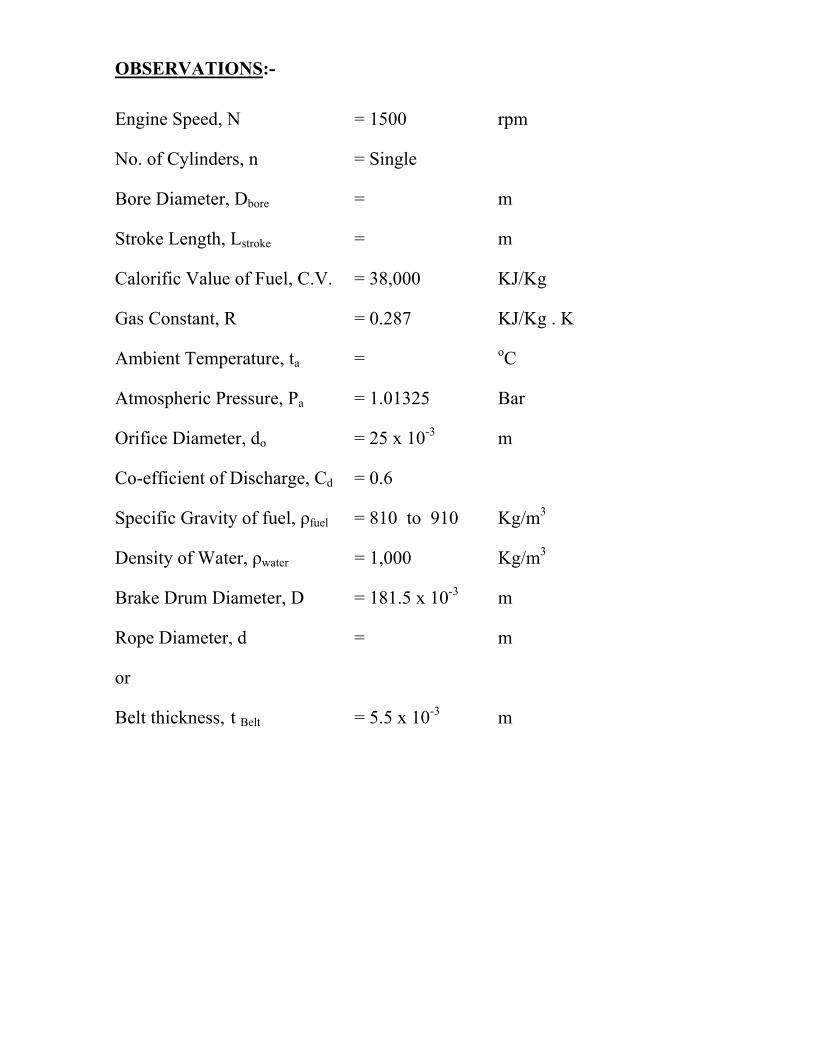
OBSERVATIONS:-
Engine Speed, N = 1500 rpm
No. of Cylinders, n = Single
Bore Diameter, Dbore = m
Stroke Length, Lstroke = m
Calorific Value of Fuel, C.V. = 38,000 KJ/Kg
Gas Constant, R = 0.287 KJ/Kg . K
Ambient Temperature, ta = oC
Atmospheric Pressure, Pa = 1.01325 Bar
Orifice Diameter, do = 25 x 10-3 m
Co-efficient of Discharge, Cd = 0.6
Specific Gravity of fuel, ρfuel = 810 to 910 Kg/m3
Density of Water, ρwater = 1,000 Kg/m3
Brake Drum Diameter, D = 181.5 x 10⁻³ m
Rope Diameter, d = m
or
Belt thickness, t Belt = 5.5 x 10⁻³ m
OBSERVATIONS TABLE :- S.
No.
Engine
Speed,
N (rpm)
Dynamometer Spring
Balance Readings, (Kg)
Time taken for 50 ml fuel,
t (Sec.)
Manometer
Reading,
∆h (m) S1
(Kg)
S2
(Kg)
1.
1500
2.
1500
3.
1500
4.
1500
CALCULATIONS:-
RESULT TABLE:-

Sl.
No.
Engine
Speed,
N (rpm)
Brake Power,
BP (KW)
Fuel Consumption,
mf (Kg/hr)
BSFC (Kg/ KW .
hr)
BMEP (N/ m2)
A/F Ratio
Air Consumption
Rate (Kg/ hr)
ηmech % age
1.
1500
2.
1500
3.
1500
4.
1500
RESULTS:- Performance curves are plotted and they are similar to the standard
performance Curves.
Viva Questions
1. What is break power ?
2. Define speed performance test on a four-stroke single – Cylinder diesel engine?
3. What is Air rate and A/F ratio in a four-stroke single – Cylinder diesel engine?
4. What is combustion phenomenon? 5. What is indicated power ?

EXPERIMENT No. 9
AIM:- To Study and Determine the effect of A/F Ratio on the performance of the
Two-Stroke, Single-Cylinder Petrol Engine.
APPARATUS USED :- Two-Stroke, Single-Cylinder Petrol Engine Test Rig,
Stop Watch, and Digital Tachometer.
THEORY:-
Air fuel ratio has a major effect on the performance of the I. C.
Engine. The Air fuel ratio of a S. I. Engine lies in the range of 10: 1, to 22: 1
depends upon the power requirements and the economic running of the engine.
Richer mixtures are required for idle and full throttle running of the engine.
Whereas for the mid-range , weaker mixtures are required. The mixture
corresponding to the minimum fuel consumption is known as the Best Economy
Mixture. It is nearly 15:1.Accurate measurement of air flow into the engine is
difficult to achieve in practice, due not only to the nature of the air itself, but also
the conditions under which the measurement has to be made.The common method
of measuring the air flow rate is the tank and orifice method. During suction stroke
the pressure inside the tank is less than the atmospheric pressure. The air enters the
tank through the orifice plate , and by applying the Bernaulli’s equation the air
flow rate can be measured. The fuel consumption can be measured by noting down
the fuel consumed during specified time. Thus the air fuel ratio can be set to
desired value. The accuracy of the air flow measurement depends on the steady
state conditions of air flow through the orifice and the damping of the pulsating
effect.

FORMULE USED:-
(i) Torque, T = 9.81 x W x R Effective N-m.
; Where R Effective = (D + d)/ 2 m, and W (Load) = ( S1 - S2 ) Kg,
(ii) Brake Power, B P = ( 2πN T ) / 60, 000 KW
; Where N = rpm, T = Torque N-m,
(iii) Fuel Consumption, m f = ( 50 ml x 10 -6 x ρ Fuel ) / ( t )
Kg/Sec.
Here; 1 ml = 10-3 liters, and 1000 liters = 1 m3
So, 1 ml = 10-6 m3
(iv) Brake Specific Fuel Consumption, BSFC = ( m f x 3600 ) / B P Kg/ KW . hr
(v) Mass of the Air, m Air = Cd Ao √2 g Δh ρ Air ρ Water Kg/ Sec
; Where Cd ( Co-efficient of Discharge ) = 0.6,
ρ Air = ( Pa x 102 ) / ( R x Ta ) Kg/ m3
Ao ( Area of Orifice ) = (π do2)/ 4 m2,
Pa = 1.01325 Bar, R = 0.287 KJ/Kg . K,
Ta = ( ta + 273 ) K, ta = Ambient Temperature OC
(vi) Air Fuel Ratio, A/F = ( m Air / m f ) Kg/ Kg of Fuel
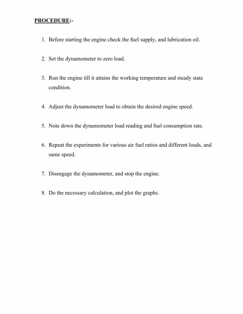
PROCEDURE:-
1. Before starting the engine check the fuel supply, and lubrication oil.
2. Set the dynamometer to zero load.
3. Run the engine till it attains the working temperature and steady state
condition.
4. Adjust the dynamometer load to obtain the desired engine speed.
5. Note down the dynamometer load reading and fuel consumption rate.
6. Repeat the experiments for various air fuel ratios and different loads, and
same speed.
7. Disengage the dynamometer, and stop the engine.
8. Do the necessary calculation, and plot the graphs.
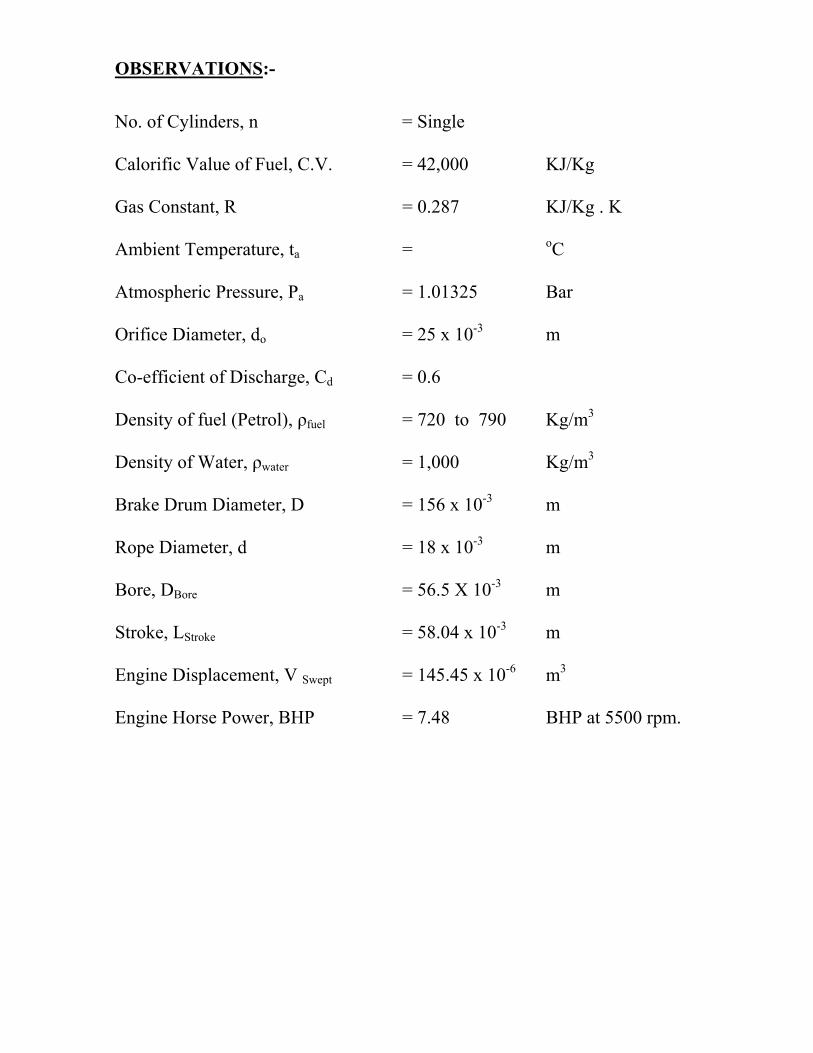
OBSERVATIONS:-
No. of Cylinders, n = Single
Calorific Value of Fuel, C.V. = 42,000 KJ/Kg
Gas Constant, R = 0.287 KJ/Kg . K
Ambient Temperature, ta = oC
Atmospheric Pressure, Pa = 1.01325 Bar
Orifice Diameter, do = 25 x 10-3 m
Co-efficient of Discharge, Cd = 0.6
Density of fuel (Petrol), ρfuel = 720 to 790 Kg/m3
Density of Water, ρwater = 1,000 Kg/m3
Brake Drum Diameter, D = 156 x 10-3 m
Rope Diameter, d = 18 x 10-3 m
Bore, DBore = 56.5 X 10⁻³ m
Stroke, LStroke = 58.04 x 10⁻³ m
Engine Displacement, V Swept = 145.45 x 10⁻⁶ m3
Engine Horse Power, BHP = 7.48 BHP at 5500 rpm.

OBSERVATIONS TABLE :-
Sl. No. Engine Speed,
N (rpm)
Dynamometer Spring
Balance Readings, (Kg)
Time taken for 50 ml
fuel,
t (Sec.)
Manometer Reading,
∆h (m)
S1
(Kg)
S2
(Kg)
1.
2.
3.
4.
CALCULATIONS:-
RESULT TABLE:- Sl.
No.
Engine Speed,
N (rpm)
Torque (N-m)
Brake Power, BP (KW)
Air Consumption
Rate mair (Kg/hr)
Fuel Consumption, mf (Kg/hr)
BSFC (Kg/ KW .
hr)
A/F Ratio, (Kg/ Kg of Fuel)
1.
2.
3.
4.
RESULTS:- Performance curves are plotted and they are similar to the standard
performance Curves.
Viva Questions
1. Mention the simplified various assumptions used in fuel Air-cycle Analysis
2. Explain the significance of the fuel-Air cycle ?
3. What is the difference between Air – Standard cycle & Fuel – Air cycle analysis?
4. Define carburetion? 5. What are the different Air – Fuel Mixture on which an Engine can be
operated? 6. Explain the rich mixture, Lean Mixture & Stoichionetric Mixture ?

EXPERIMENT No. 10
AIM:- To study and draw the valve timings diagram Four-Stroke, Single-Cylinder
Diesel Engine.
APPARATUS USED :- Four-Stroke, Single-Cylinder Diesel Engine Test Rig,
Sprit Level,Marking Pencil, and Device for measuring crank angle.
THEORY :-
In four- stroke S. I. Engine the opening and closing of the valves, and the ignition
of the air fuel mixture do not take place exactly at the dead centre positions. The
valve open slightly earlier and close after their respective dead centre positions.
The ignition also occurs prior, to the mixture is fully compressed, and the piston
reaches the top dead centre position.Similarly in a C. I. Engine both the valves do
not open and close exactly at dead centre positions, rather operate at some degree
on either side in terms of the crank angles from the dead centre positions. The
injection of the fuel is also timed to occur earlier.
PROCEDURE:-
1) Fix a plate on the body of the Engine touching the flywheel.
2) Mark the positions of the both the dead centers on the flywheel with the
reference to the fixed plate. TDC and BDC in case of vertical Engines, IDC
and ODC in case of horizontal Engines.
3) Mark on the flywheel when the inlet and exhaust valves open and close as
the flywheel is rotated slowly.
4) Measure the valves (Tappet) Clearance.
5) Mark the spark ignition timing in case of petrol Engine and fuel injection
timing in case of Diesel Engine.
6) Measure the angles of the various events and plot the valve timing diagram.

OBSERVATIONS TABLE :- Sl. No. Engine Types Tappet Clearance Valve Timings
Inlet Valve
( mm ) Exhaust
Valve
( mm )
Inlet Valve Exhaust Valve Injection
Timing
( O )
Open
( O )
Close
( O )
Open
( O )
Close
( O )
1.
Four-Stroke,
Single-
Cylinder
(Vertical)
Diesel Engine.
CALCULATIONS:-
RESULT:-Based on final calculation valve timing diagram is drawn and compare
with the standard valve timing diagram. Viva Questions
1. Define valve timing in four stroke petrol engine?
2. What is overlapping?
3. What is inlet valve?
4. What is exhaust valve?
5. What do you mean by ignition?
6. What are the various types of ignition systems that are commonly used?
Top Related