


Languages
Pages
Legal

KODAK Dental Radiography Series
SUCCESSFULPANORAMICRADIOGRAPHY
3 Continuing DentalEducation Credits
Sponsored byThe Academy of Dental Therapeutics and
Stomatology
Intr
oduc
tion
2
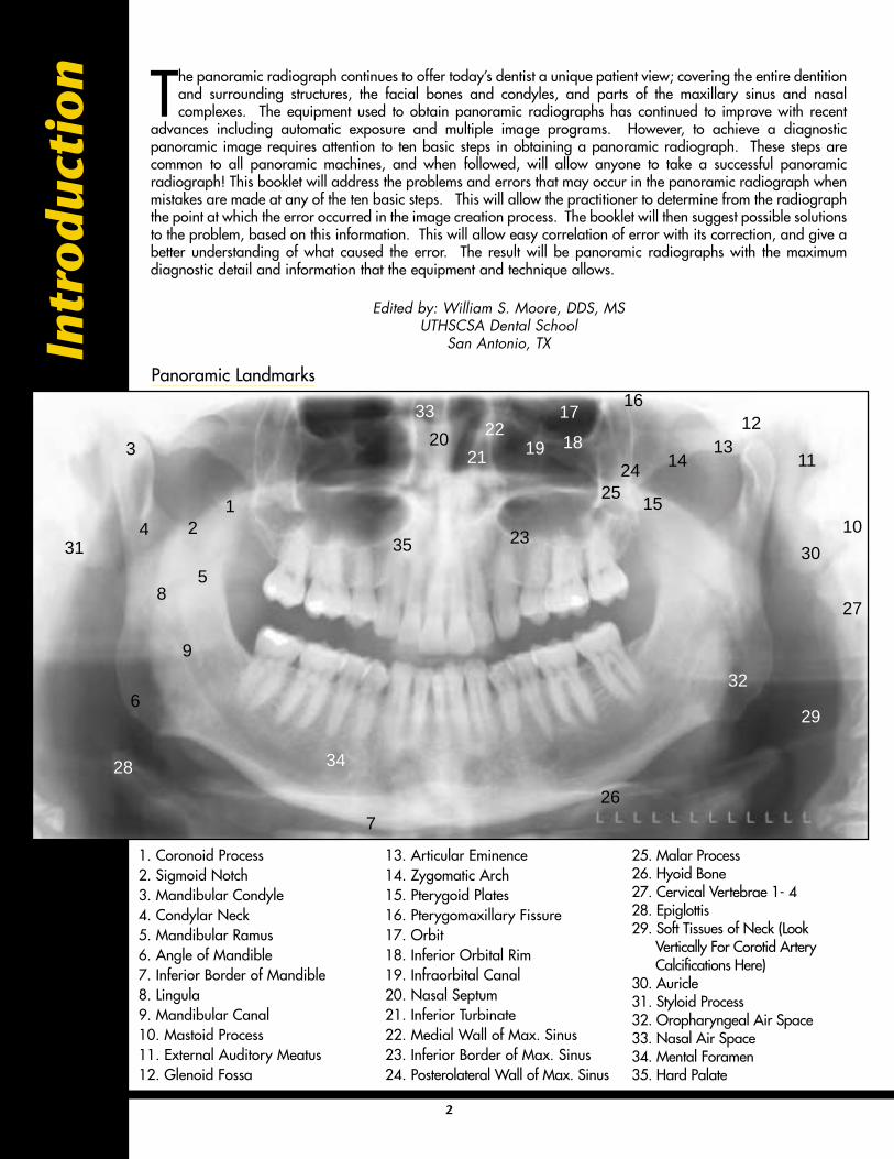
The panoramic radiograph continues to offer today’s dentist a unique patient view; covering the entire dentitionand surrounding structures, the facial bones and condyles, and parts of the maxillary sinus and nasalcomplexes. The equipment used to obtain panoramic radiographs has continued to improve with recent
advances including automatic exposure and multiple image programs. However, to achieve a diagnosticpanoramic image requires attention to ten basic steps in obtaining a panoramic radiograph. These steps arecommon to all panoramic machines, and when followed, will allow anyone to take a successful panoramicradiograph! This booklet will address the problems and errors that may occur in the panoramic radiograph whenmistakes are made at any of the ten basic steps. This will allow the practitioner to determine from the radiographthe point at which the error occurred in the image creation process. The booklet will then suggest possible solutionsto the problem, based on this information. This will allow easy correlation of error with its correction, and give abetter understanding of what caused the error. The result will be panoramic radiographs with the maximumdiagnostic detail and information that the equipment and technique allows.
Edited by: William S. Moore, DDS, MSUTHSCSA Dental School
San Antonio, TX
12
3
4
5
6
7
8
9
10
11
1213
14
15
1617
18192021
22
23
2425
26
35
27
28
29
3031
32
34
33
1. Coronoid Process2. Sigmoid Notch3. Mandibular Condyle4. Condylar Neck5. Mandibular Ramus6. Angle of Mandible7. Inferior Border of Mandible8. Lingula9. Mandibular Canal10. Mastoid Process11. External Auditory Meatus12. Glenoid Fossa
13. Articular Eminence14. Zygomatic Arch15. Pterygoid Plates16. Pterygomaxillary Fissure17. Orbit18. Inferior Orbital Rim19. Infraorbital Canal20. Nasal Septum21. Inferior Turbinate22. Medial Wall of Max. Sinus23. Inferior Border of Max. Sinus24. Posterolateral Wall of Max. Sinus
25. Malar Process26. Hyoid Bone27. Cervical Vertebrae 1- 428. Epiglottis29. Soft Tissues of Neck (Look
Vertically For Corotid Artery Calcifications Here)
30. Auricle31. Styloid Process32. Oropharyngeal Air Space33. Nasal Air Space34. Mental Foramen35. Hard Palate
Panoramic Landmarks
Panoramic Theory
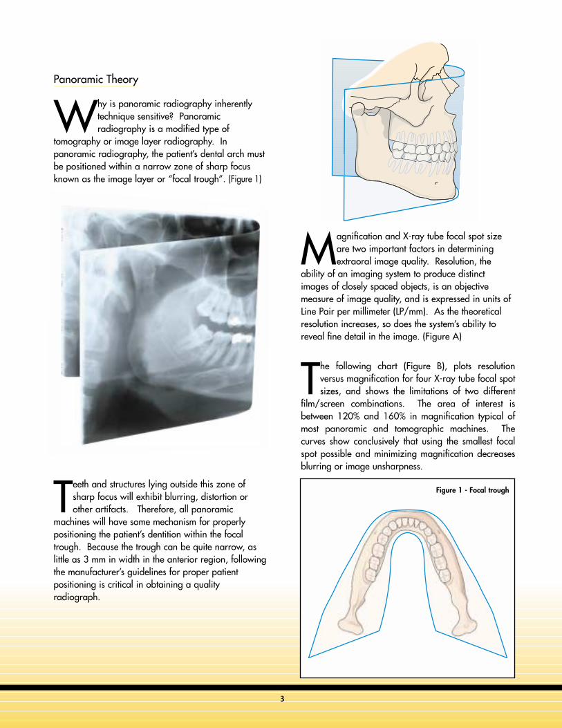
Why is panoramic radiography inherentlytechnique sensitive? Panoramicradiography is a modified type of
tomography or image layer radiography. Inpanoramic radiography, the patient’s dental arch mustbe positioned within a narrow zone of sharp focusknown as the image layer or “focal trough”. (Figure 1)
Teeth and structures lying outside this zone ofsharp focus will exhibit blurring, distortion orother artifacts. Therefore, all panoramic
machines will have some mechanism for properlypositioning the patient’s dentition within the focaltrough. Because the trough can be quite narrow, aslittle as 3 mm in width in the anterior region, followingthe manufacturer’s guidelines for proper patientpositioning is critical in obtaining a qualityradiograph.
Magnification and X-ray tube focal spot sizeare two important factors in determiningextraoral image quality. Resolution, the
ability of an imaging system to produce distinctimages of closely spaced objects, is an objectivemeasure of image quality, and is expressed in units ofLine Pair per millimeter (LP/mm). As the theoreticalresolution increases, so does the system’s ability toreveal fine detail in the image. (Figure A)
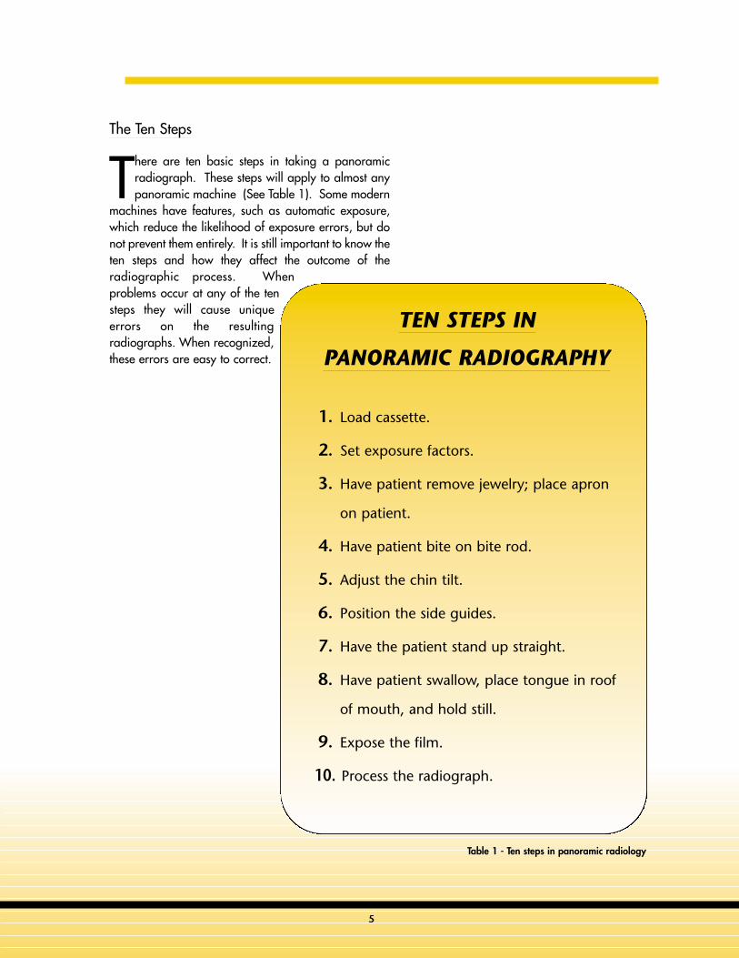
The following chart (Figure B), plots resolutionversus magnification for four X-ray tube focal spotsizes, and shows the limitations of two different
film/screen combinations. The area of interest isbetween 120% and 160% in magnification typical ofmost panoramic and tomographic machines. Thecurves show conclusively that using the smallest focalspot possible and minimizing magnification decreasesblurring or image unsharpness.
Figure 1 - Focal trough
3
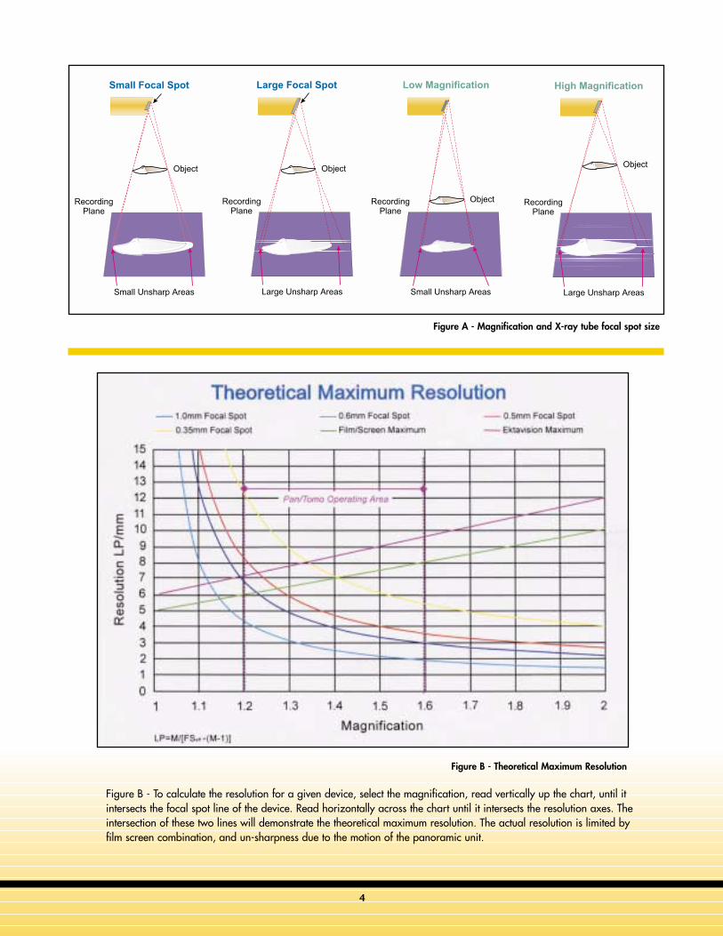
Figure A - Magnification and X-ray tube focal spot size
Figure B - Theoretical Maximum Resolution
4
Figure B - To calculate the resolution for a given device, select the magnification, read vertically up the chart, until itintersects the focal spot line of the device. Read horizontally across the chart until it intersects the resolution axes. Theintersection of these two lines will demonstrate the theoretical maximum resolution. The actual resolution is limited byfilm screen combination, and un-sharpness due to the motion of the panoramic unit.
5
The Ten Steps
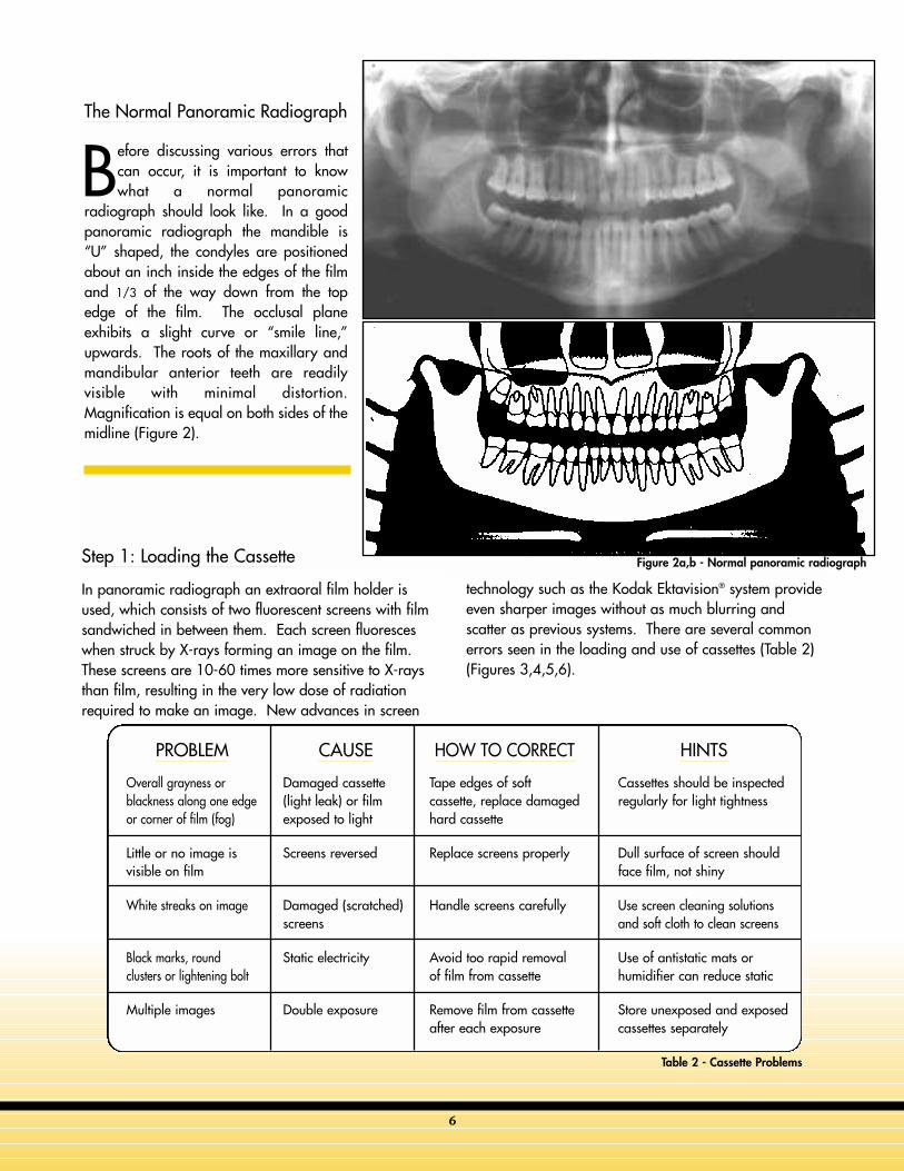
There are ten basic steps in taking a panoramicradiograph. These steps will apply to almost anypanoramic machine (See Table 1). Some modern
machines have features, such as automatic exposure,which reduce the likelihood of exposure errors, but donot prevent them entirely. It is still important to know theten steps and how they affect the outcome of theradiographic process. Whenproblems occur at any of the tensteps they will cause uniqueerrors on the resultingradiographs. When recognized,these errors are easy to correct.
TEN STEPS IN
PANORAMIC RADIOGRAPHY
1. Load cassette.
2. Set exposure factors.
3. Have patient remove jewelry; place apron
on patient.
4. Have patient bite on bite rod.
5. Adjust the chin tilt.
6. Position the side guides.
7. Have the patient stand up straight.
8. Have patient swallow, place tongue in roof
of mouth, and hold still.
9. Expose the film.
10. Process the radiograph.
Table 1 - Ten steps in panoramic radiology
The Normal Panoramic Radiograph
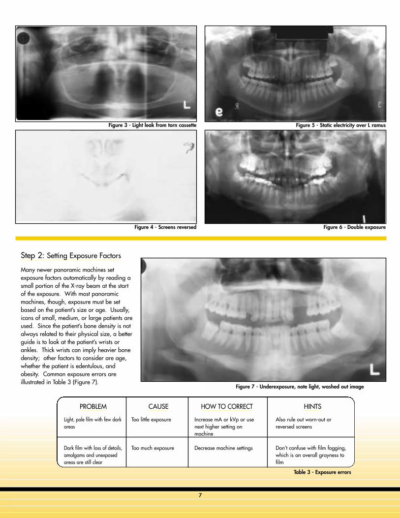
Before discussing various errors thatcan occur, it is important to knowwhat a normal panoramic
radiograph should look like. In a goodpanoramic radiograph the mandible is“U” shaped, the condyles are positionedabout an inch inside the edges of the filmand 1/3 of the way down from the topedge of the film. The occlusal planeexhibits a slight curve or “smile line,”upwards. The roots of the maxillary andmandibular anterior teeth are readilyvisible with minimal distortion.Magnification is equal on both sides of themidline (Figure 2).
Step 1: Loading the Cassette
In panoramic radiograph an extraoral film holder isused, which consists of two fluorescent screens with filmsandwiched in between them. Each screen fluoresceswhen struck by X-rays forming an image on the film.These screens are 10-60 times more sensitive to X-raysthan film, resulting in the very low dose of radiationrequired to make an image. New advances in screen
technology such as the Kodak Ektavision® system provideeven sharper images without as much blurring andscatter as previous systems. There are several commonerrors seen in the loading and use of cassettes (Table 2)(Figures 3,4,5,6).
Figure 2a,b - Normal panoramic radiograph
Table 2 - Cassette Problems
PROBLEM
Overall grayness orblackness along one edgeor corner of film (fog)
Little or no image isvisible on film
White streaks on image
Black marks, roundclusters or lightening bolt
Multiple images
CAUSE
Damaged cassette(light leak) or filmexposed to light
Screens reversed
Damaged (scratched)screens
Static electricity
Double exposure
HOW TO CORRECT
Tape edges of softcassette, replace damagedhard cassette
Replace screens properly
Handle screens carefully
Avoid too rapid removalof film from cassette
Remove film from cassetteafter each exposure
HINTS
Cassettes should be inspectedregularly for light tightness
Dull surface of screen shouldface film, not shiny
Use screen cleaning solutionsand soft cloth to clean screens
Use of antistatic mats orhumidifier can reduce static
Store unexposed and exposedcassettes separately
6
PROBLEM
Light, pale film with few darkareas
Dark film with loss of details,amalgams and unexposedareas are still clear
CAUSE
Too little exposure
Too much exposure
HOW TO CORRECT
Increase mA or kVp or usenext higher setting onmachine
Decrease machine settings
HINTS
Also rule out worn-out orreversed screens
Don’t confuse with film fogging,which is an overall grayness tofilm
Table 3 - Exposure errors
Step 2: Setting Exposure Factors
Many newer panoramic machines setexposure factors automatically by reading asmall portion of the X-ray beam at the startof the exposure. With most panoramicmachines, though, exposure must be setbased on the patient’s size or age. Usually,icons of small, medium, or large patients areused. Since the patient’s bone density is notalways related to their physical size, a betterguide is to look at the patient’s wrists orankles. Thick wrists can imply heavier bonedensity; other factors to consider are age,whether the patient is edentulous, andobesity. Common exposure errors areillustrated in Table 3 (Figure 7).
Figure 3 - Light leak from torn cassette
Figure 4 - Screens reversed
Figure 5 - Static electricity over L ramus
Figure 6 - Double exposure
Figure 7 - Underexposure, note light, washed out image
7
8
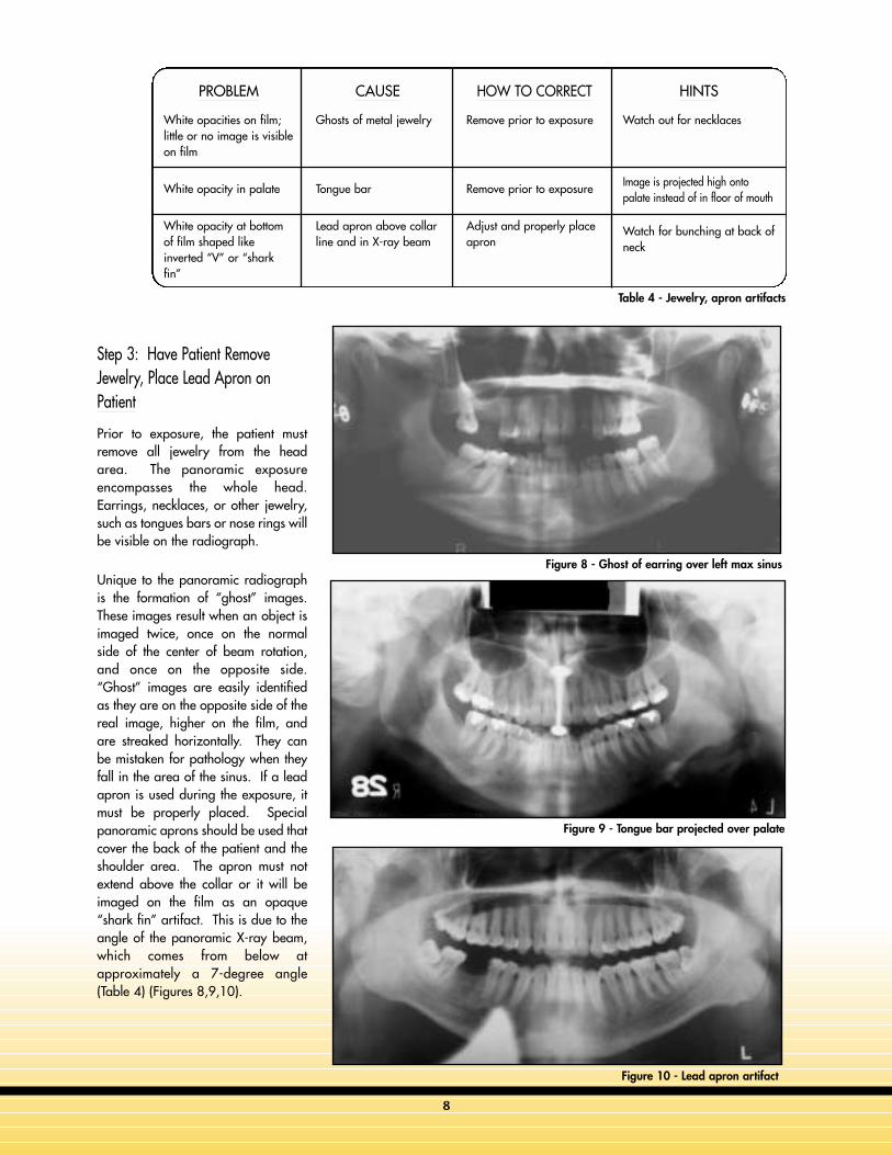
Step 3: Have Patient RemoveJewelry, Place Lead Apron onPatient
Prior to exposure, the patient mustremove all jewelry from the headarea. The panoramic exposureencompasses the whole head.Earrings, necklaces, or other jewelry,such as tongues bars or nose rings willbe visible on the radiograph.
Unique to the panoramic radiographis the formation of “ghost” images.These images result when an object isimaged twice, once on the normalside of the center of beam rotation,and once on the opposite side.“Ghost” images are easily identifiedas they are on the opposite side of thereal image, higher on the film, andare streaked horizontally. They canbe mistaken for pathology when theyfall in the area of the sinus. If a leadapron is used during the exposure, itmust be properly placed. Specialpanoramic aprons should be used thatcover the back of the patient and theshoulder area. The apron must notextend above the collar or it will beimaged on the film as an opaque“shark fin” artifact. This is due to theangle of the panoramic X-ray beam,which comes from below atapproximately a 7-degree angle(Table 4) (Figures 8,9,10).
PROBLEM
White opacities on film;little or no image is visibleon film
White opacity in palate
White opacity at bottomof film shaped likeinverted “V” or “sharkfin”
CAUSE
Ghosts of metal jewelry
Tongue bar
Lead apron above collarline and in X-ray beam
HOW TO CORRECT
Remove prior to exposure
Remove prior to exposure
Adjust and properly placeapron
HINTS
Watch out for necklaces
Image is projected high ontopalate instead of in floor of mouth
Watch for bunching at back ofneck
Figure 8 - Ghost of earring over left max sinus
Table 4 - Jewelry, apron artifacts
Figure 9 - Tongue bar projected over palate
Figure 10 - Lead apron artifact
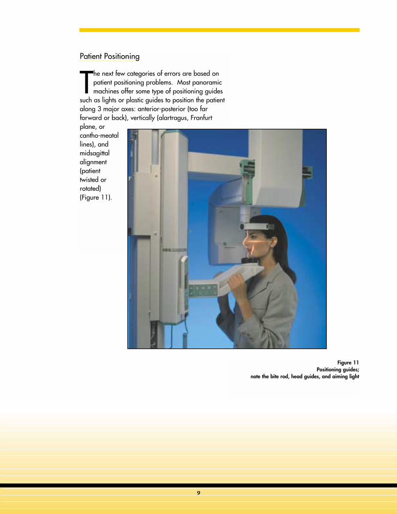
Patient Positioning
The next few categories of errors are based onpatient positioning problems. Most panoramicmachines offer some type of positioning guides
such as lights or plastic guides to position the patientalong 3 major axes: anterior-posterior (too farforward or back), vertically (alartragus, Franfurtplane, orcantho-meatallines), andmidsagittalalignment(patienttwisted orrotated)(Figure 11).
Figure 11Positioning guides;
note the bite rod, head guides, and aiming light
9
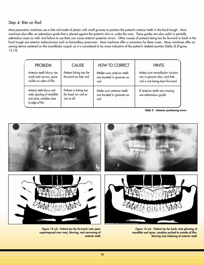
Step 4: Bite on Rod
Most panoramic machines use a bite rod made of plastic with small grooves to position the patient’s anterior teeth in the focal trough. Mostmachines also offer an edentulous guide that is placed against the patient’s chin or under the nose. These guides are also useful in partiallyedentulous cases as well, and failure to use them can cause anterior-posterior errors. Other causes of patients being too far forward or back in thefocal trough are anterior malocclusions such as bimaxillary protrusion. Most machines offer a correction for these cases. Many machines offer anaiming device centered on the mandibular cuspid, as it is considered to be more indicative of the patient’s skeletal position (Table 5) (Figures12,13).
PROBLEM
Anterior teeth blurry, toosmall and narrow, spinevisible on sides of film
Anterior teeth blurry andwide, ghosting of mandibleand spine, condyles closeto edge of film
CAUSE
Patient biting too farforward on bite rod
Patient is biting toofar back on rod ornot at all
HOW TO CORRECT
Make sure anterior teethare located in grooves onrod
Make sure anterior teethare located in grooves onrod
HINTS
Make sure mandibular incisorsare in groove also, and biterod is not being bent forward
If anterior teeth are missinguse edentulous guide
Table 5 - Anterior positioning errors
Figure 12 a,b - Patient too far forward; note spinesuperimposed over rami, blurring, and narrowing of
anterior teeth
Figure 13 a,b - Patient too far back; note ghosting ofmandible and spine, condyles pushed to outside of film,
blurring and widening of anterior teeth
10
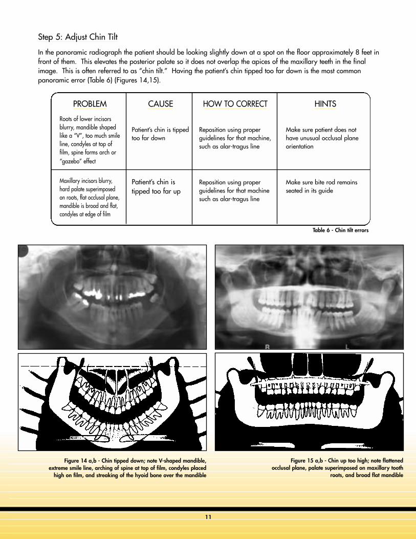
Step 5: Adjust Chin Tilt
In the panoramic radiograph the patient should be looking slightly down at a spot on the floor approximately 8 feet infront of them. This elevates the posterior palate so it does not overlap the apices of the maxillary teeth in the finalimage. This is often referred to as “chin tilt.” Having the patient’s chin tipped too far down is the most commonpanoramic error (Table 6) (Figures 14,15).
PROBLEM
Roots of lower incisorsblurry, mandible shapedlike a “V”, too much smileline, condyles at top offilm, spine forms arch or“gazebo” effect
Maxillary incisors blurry,hard palate superimposedon roots, flat occlusal plane,mandible is broad and flat,condyles at edge of film
CAUSE
Patient’s chin is tippedtoo far down
Patient’s chin istipped too far up
HOW TO CORRECT
Reposition using properguidelines for that machine,such as alar-tragus line
Reposition using properguidelines for that machinesuch as alar-tragus line
HINTS
Make sure patient does nothave unusual occlusal planeorientation
Make sure bite rod remainsseated in its guide
Figure 14 a,b - Chin tipped down; note V-shaped mandible,extreme smile line, arching of spine at top of film, condyles placed
high on film, and streaking of the hyoid bone over the mandible
Figure 15 a,b - Chin up too high; note flattenedocclusal plane, palate superimposed on maxillary tooth
roots, and broad flat mandible
Table 6 - Chin tilt errors
11
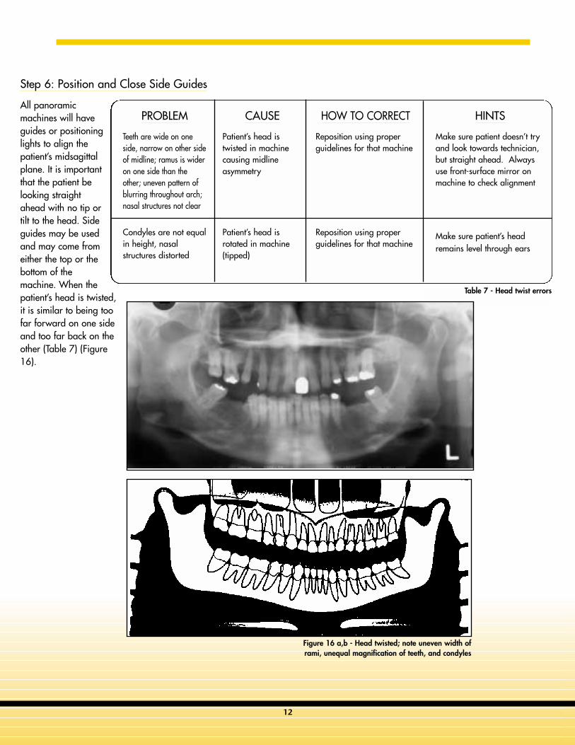
Step 6: Position and Close Side Guides
All panoramicmachines will haveguides or positioninglights to align thepatient’s midsagittalplane. It is importantthat the patient belooking straightahead with no tip ortilt to the head. Sideguides may be usedand may come fromeither the top or thebottom of themachine. When thepatient’s head is twisted,it is similar to being toofar forward on one sideand too far back on theother (Table 7) (Figure16).
PROBLEM
Teeth are wide on oneside, narrow on other sideof midline; ramus is wideron one side than theother; uneven pattern ofblurring throughout arch;nasal structures not clear
Condyles are not equalin height, nasalstructures distorted
CAUSE
Patient’s head istwisted in machinecausing midlineasymmetry
Patient’s head isrotated in machine(tipped)
HOW TO CORRECT
Reposition using properguidelines for that machine
Reposition using properguidelines for that machine
HINTS
Make sure patient doesn’t tryand look towards technician,but straight ahead. Alwaysuse front-surface mirror onmachine to check alignment
Make sure patient’s headremains level through ears
Table 7 - Head twist errors
Figure 16 a,b - Head twisted; note uneven width oframi, unequal magnification of teeth, and condyles
12
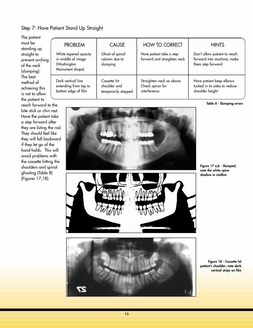
Figure 17 a,b - Slumped;note the white spineshadow in midline
Step 7: Have Patient Stand Up Straight
The patientmust bestanding upstraight toprevent archingof the neck(slumping).The bestmethod ofachieving thisis not to allowthe patient toreach forward to thebite stick or chin rest.Have the patient takea step forward afterthey are biting the rod.They should feel likethey will fall backwardif they let go of thehand-holds. This willavoid problems withthe cassette hitting theshoulders and spinalghosting (Table 8)(Figures 17,18).
PROBLEM
White tapered opacityin middle of image(WashingtonMonument shape)
Dark vertical lineextending from top tobottom edge of film
CAUSE
Ghost of spinalcolumn due toslumping
Cassette hitshoulder andtemporarily stopped
HOW TO CORRECT
Have patient take a stepforward and straighten neck
Straighten neck as above.Check apron forinterference
HINTS
Don’t allow patient to reachforward into machine; makethem step forward
Have patient keep elbowstucked in to sides to reduceshoulder height
Figure 18 - Cassette hitpatient’s shoulder; note dark
vertical stripe on film
Table 8 - Slumping errors
13
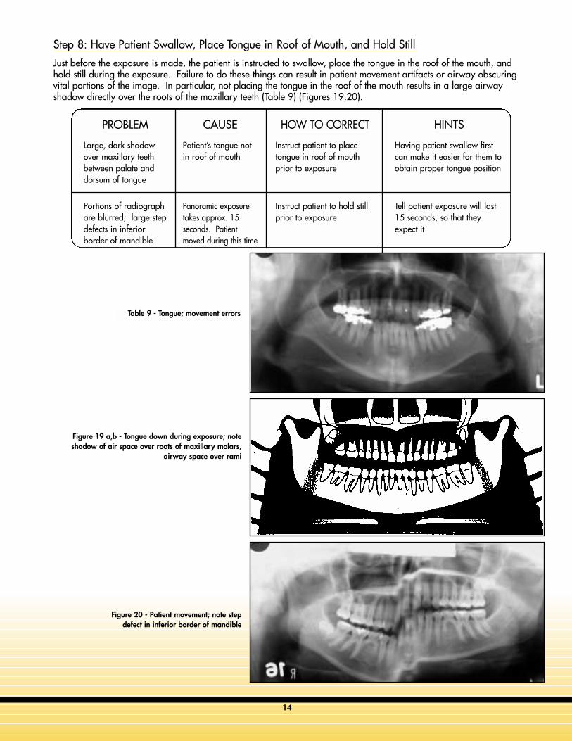
Step 8: Have Patient Swallow, Place Tongue in Roof of Mouth, and Hold Still
Just before the exposure is made, the patient is instructed to swallow, place the tongue in the roof of the mouth, andhold still during the exposure. Failure to do these things can result in patient movement artifacts or airway obscuringvital portions of the image. In particular, not placing the tongue in the roof of the mouth results in a large airwayshadow directly over the roots of the maxillary teeth (Table 9) (Figures 19,20).
PROBLEM
Large, dark shadowover maxillary teethbetween palate anddorsum of tongue
Portions of radiographare blurred; large stepdefects in inferiorborder of mandible
CAUSE
Patient’s tongue notin roof of mouth
Panoramic exposuretakes approx. 15seconds. Patientmoved during this time
HOW TO CORRECT
Instruct patient to placetongue in roof of mouthprior to exposure
Instruct patient to hold stillprior to exposure
HINTS
Having patient swallow firstcan make it easier for them toobtain proper tongue position
Tell patient exposure will last15 seconds, so that theyexpect it
Table 9 - Tongue; movement errors
Figure 19 a,b - Tongue down during exposure; noteshadow of air space over roots of maxillary molars,
airway space over rami
Figure 20 - Patient movement; note stepdefect in inferior border of mandible
14
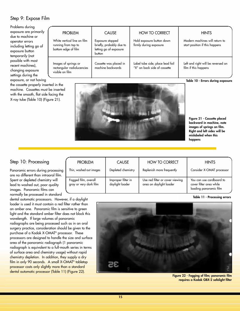
Table 11 - Processing errors
Figure 21 - Cassette placedbackward in machine, noteimages of springs on film.Right and left sides will bemislabeled when thishappens
Step 10: Processing
Panoramic errors during processingare no different than intraoral film.Spent or depleted chemistry willlead to washed out, poor qualityimages. Panoramic films cannormally be processed in standarddental automatic processors. However, if a daylightloader is used it must contain a red filter rather thanan amber one. Panoramic film is sensitive to greenlight and the standard amber filter does not block thiswavelength. If large volumes of panoramicradiographs are being processed such as in an oralsurgery practice, consideration should be given to thepurchase of a Kodak X-OMAT® processor. Theseprocessors are designed to handle the size and surfacearea of the panoramic radiograph (1 panoramicradiograph is equivalent to a full-mouth series in termsof surface area and chemistry usage) without rapidchemistry depletion. In addition, they supply a dryfilm in only 90 seconds. A small X-OMAT® tabletopprocessor costs only slightly more than a standarddental automatic processor (Table 11) (Figure 22).
Step 9: Expose Film
Problems duringexposure are primarilydue to machine oroperator errorsincluding letting go ofexposure buttontemporarily (notpossible with mostrecent machines),changing exposuresettings during theexposure, or not havingthe cassette properly inserted in themachine. Cassettes must be insertedwith the smooth, flat side facing theX-ray tube (Table 10) (Figure 21).
PROBLEM
White vertical line on filmrunning from top tobottom edge of film
Images of springs orrectangular radiolucenciesvisible on film
CAUSE
Exposure stoppedbriefly, probably due toletting go of exposurebutton
Cassette was placed inmachine backwards
HOW TO CORRECT
Hold exposure button downfirmly during exposure
Label tube side; place lead foil“X” on back side of cassette
HINTS
Modern machines will return tostart position if this happens
Left and right will be reversed onfilm if this happens
PROBLEM
Thin, washed-out images
Fogged film, overallgray or very dark film
CAUSE
Depleted chemistry
Improper filter indaylight loader
HOW TO CORRECT
Replenish more frequently
Use red filter or cover viewingarea on daylight loader
HINTS
Consider X-OMAT processor
You can use cardboard tocover filter area whileloading panoramic film
Figure 22 - Fogging of film; panoramic filmrequires a Kodak GBX-2 safelight filter
Table 10 - Errors during exposure
15
16
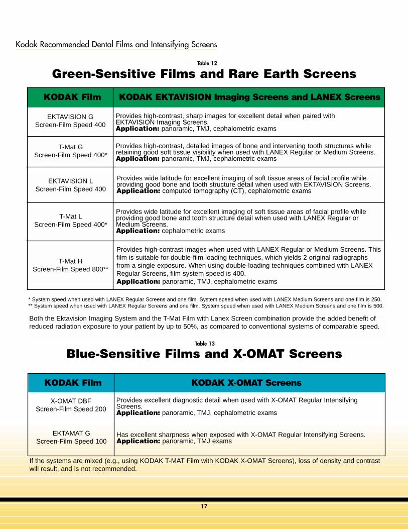
Screen/film combinations come in different speeds. The faster the film speed, the lower the radiation dose to the patient.The approximate relative speeds and sensitivities of Kodak screen-film combinations are shown in Tables 12 and 13.Screens and films also vary by the type of light that they react to. Some react to ultraviolet light, others react to blue light,
still others to green light. Table 12 presents values for green-emitting Lanex and InSight screens and green-sensitive films.Table 13 presents values for ultraviolet-emitting Kodak X-Omat screens and blue-emitting calcium tungstate screens with blue-sensitive films. Screens and films are not interchangeable. It is important to use a blue-emitting screen with a film that is bluesensitive and a green-emitting screen with a film that is green sensitive.
Film / Film Combinations and Speeds
Film Theory - Image Receptor
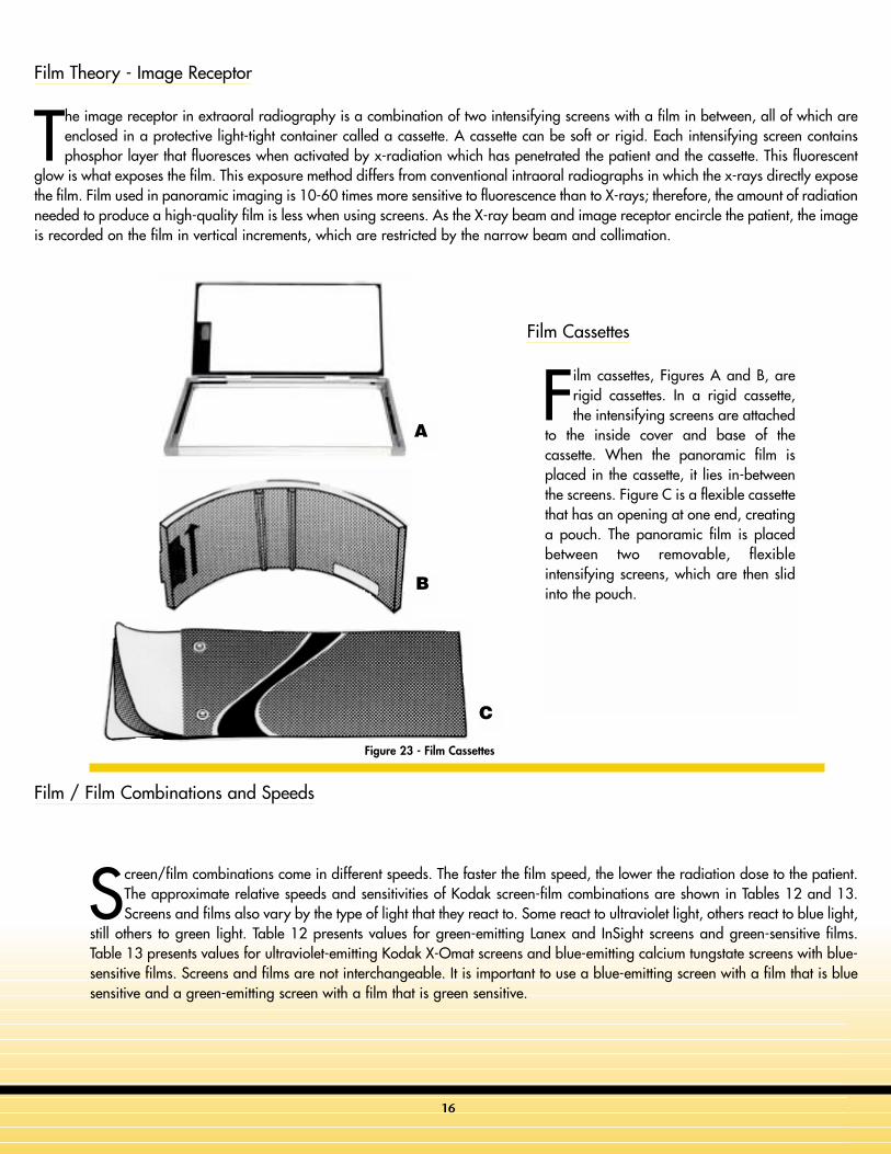
The image receptor in extraoral radiography is a combination of two intensifying screens with a film in between, all of which areenclosed in a protective light-tight container called a cassette. A cassette can be soft or rigid. Each intensifying screen containsphosphor layer that fluoresces when activated by x-radiation which has penetrated the patient and the cassette. This fluorescent
glow is what exposes the film. This exposure method differs from conventional intraoral radiographs in which the x-rays directly exposethe film. Film used in panoramic imaging is 10-60 times more sensitive to fluorescence than to X-rays; therefore, the amount of radiationneeded to produce a high-quality film is less when using screens. As the X-ray beam and image receptor encircle the patient, the imageis recorded on the film in vertical increments, which are restricted by the narrow beam and collimation.
Film cassettes, Figures A and B, arerigid cassettes. In a rigid cassette,the intensifying screens are attached
to the inside cover and base of thecassette. When the panoramic film isplaced in the cassette, it lies in-betweenthe screens. Figure C is a flexible cassettethat has an opening at one end, creatinga pouch. The panoramic film is placedbetween two removable, flexibleintensifying screens, which are then slidinto the pouch.
C
B
Film Cassettes
Figure 23 - Film Cassettes
A
17
KODAK Film KODAK EKTAVISION Imaging Screens and LANEX Screens
EKTAVISION GScreen-Film Speed 400
Provides high-contrast, sharp images for excellent detail when paired with EKTAVISION Imaging Screens.Application: panoramic, TMJ, cephalometric exams
Provides high-contrast, detailed images of bone and intervening tooth structures whileretaining good soft tissue visibility when used with LANEX Regular or Medium Screens.Application: panoramic, TMJ, cephalometric exams
Provides wide latitude for excellent imaging of soft tissue areas of facial profile whileproviding good bone and tooth structure detail when used with EKTAVISION Screens.Application: computed tomography (CT), cephalometric exams
Provides wide latitude for excellent imaging of soft tissue areas of facial profile whileproviding good bone and tooth structure detail when used with LANEX Regular orMedium Screens.Application: cephalometric exams
Provides high-contrast images when used with LANEX Regular or Medium Screens. Thisfilm is suitable for double-film loading techniques, which yields 2 original radiographsfrom a single exposure. When using double-loading techniques combined with LANEXRegular Screens, film system speed is 400.Application: panoramic, TMJ, cephalometric exams
T-Mat GScreen-Film Speed 400*
T-Mat LScreen-Film Speed 400*
T-Mat HScreen-Film Speed 800**
EKTAVISION LScreen-Film Speed 400
Green-Sensitive Films and Rare Earth Screens
KODAK Film KODAK X-OMAT Screens
X-OMAT DBFScreen-Film Speed 200
Provides excellent diagnostic detail when used with X-OMAT Regular IntensifyingScreens.Application: panoramic, TMJ, cephalometric exams
Has excellent sharpness when exposed with X-OMAT Regular Intensifying Screens.Application: panoramic, TMJ exams
EKTAMAT GScreen-Film Speed 100
Blue-Sensitive Films and X-OMAT Screens
Kodak Recommended Dental Films and Intensifying Screens
* System speed when used with LANEX Regular Screens and one film. System speed when used with LANEX Medium Screens and one film is 250.** System speed when used with LANEX Regular Screens and one film. System speed when used with LANEX Medium Screens and one film is 500.
Both the Ektavision Imaging System and the T-Mat Film with Lanex Screen combination provide the added benefit ofreduced radiation exposure to your patient by up to 50%, as compared to conventional systems of comparable speed.
If the systems are mixed (e.g., using KODAK T-MAT Film with KODAK X-OMAT Screens), loss of density and contrastwill result, and is not recommended.
Table 12
Table 13
18
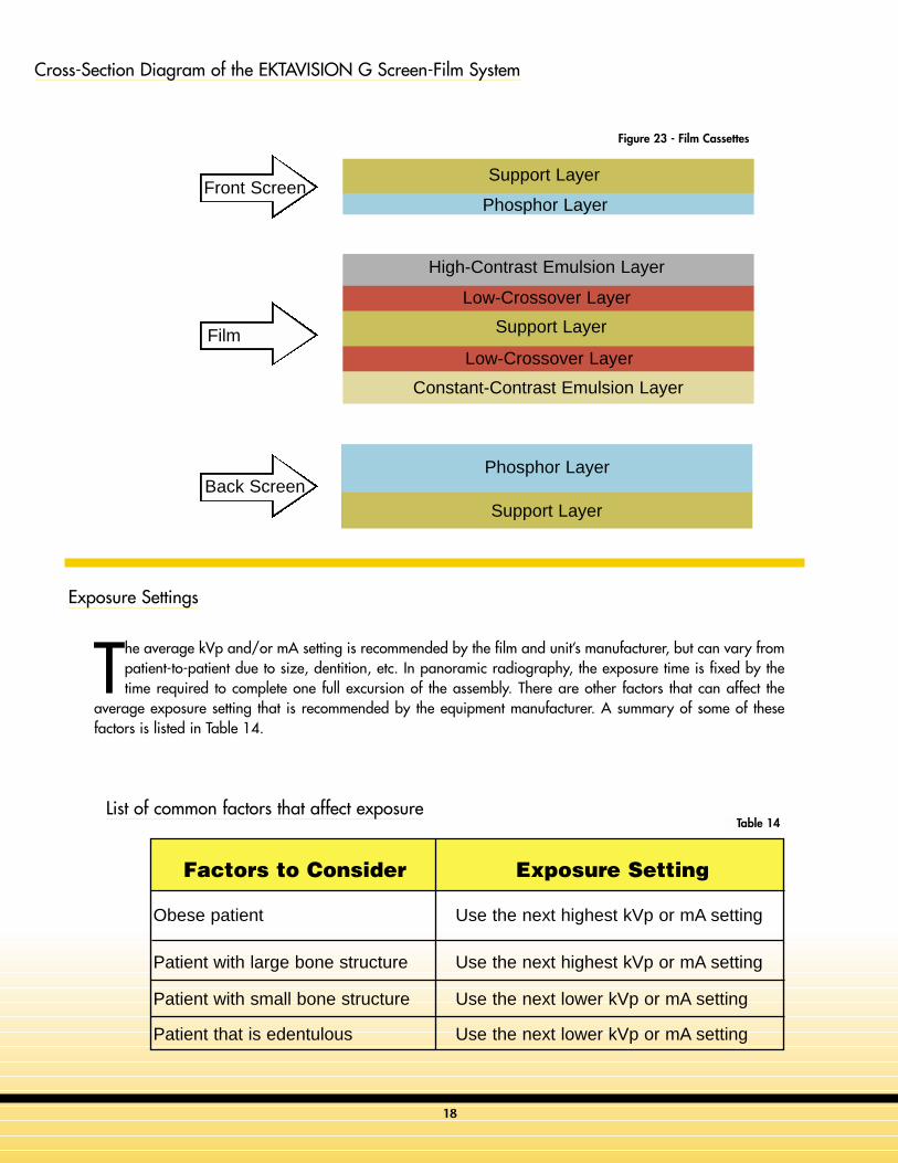
Front Screen
Back Screen
Film
Support Layer
Low-Crossover Layer
Constant-Contrast Emulsion Layer
Low-Crossover Layer
High-Contrast Emulsion Layer
Phosphor Layer
Phosphor Layer
Support Layer
Support Layer
Cross-Section Diagram of the EKTAVISION G Screen-Film System
Exposure Settings
List of common factors that affect exposure
The average kVp and/or mA setting is recommended by the film and unit’s manufacturer, but can vary frompatient-to-patient due to size, dentition, etc. In panoramic radiography, the exposure time is fixed by thetime required to complete one full excursion of the assembly. There are other factors that can affect the
average exposure setting that is recommended by the equipment manufacturer. A summary of some of thesefactors is listed in Table 14.
Factors to Consider Exposure Setting
Obese patient Use the next highest kVp or mA setting
Patient with large bone structure Use the next highest kVp or mA setting
Patient with small bone structure Use the next lower kVp or mA setting
Patient that is edentulous Use the next lower kVp or mA setting
Table 14
Figure 23 - Film Cassettes

Test Questions
1. The area of sharp focus inpanoramic radiography isknown as the:
a. exposure zoneb. focal troughc. aiming grooved. tomographic zone
2. The focal trough can be asnarrow as _____ mm in theanterior region, making properimaging of the lower incisorsdifficult.
a. 1 mmb. 2 mmc. 3 mmd. 5 mm
3. There are approximately _____steps to follow in taking asuccessful panoramic image.
a. 3b. 5 c. 7d. 10
4. Screens used in panoramicimaging cassettes areapproximately ______timesmore sensitive to x-radiationthan film.
a. 5-30b. 5-40c. 10-60d. 10-80
5. A dark black or gray areaoriginating on one edge orcorner of the film is mostlikely due to:
a. damaged screen b. damaged cassette (light leak)c. reversed screensd. static electricity
6. A film that is very dark withloss of detail is most likelydue to:
a. underexposureb. overexposure c. processor failured. film too cold
7. A white inverted V-shapedradiopacity on the bottom ofthe film is most likely causedby:
a. ghosts of metal jewelryb. ghost of hyoid bone c. lead apron artifactd. damaged cassette
8. A panoramic radiographshows small, narrowedanterior teeth with the spinevisible on both sides of thefilm. The patient was probablypositioned ______on the biterod.
a. too far forward b. too far backc. too highd. too low
9. A panoramic radiograph showsthe mandible to be V-shapedand narrowed with the condyleshigh on the film. The occlusalcurve is exaggerated and thespine arches over top of thefilm. The patient’s head tilt wasmost likely pointing ______.
a. too highb. too low c. tippedd. twisted
10. A large tapered verticalradiopacity in the center of thepanoramic radiograph isusually caused by the ghost ofthe spine due to:
a. patient is too far back in themachine
b. patient’s head tilted too far upc. patient was slumping, neck was
curved d. patient’s head was twisted
11. When the patient is properlypositioned in the panoramicmachine, they should feel:
a. very comfortable b. nervousc. like they will fall backwards if
they let go of the handholdsd. like they are leaning forward
12. If the patient fails to hold thetongue in the roof of themouth:
a. a large black shadow will bepresent between the tongue andpalate
b. roots of the maxillary teeth maybe obscured
c. an airway shadow will resultd. all of the above
13. After development, apanoramic radiograph showsstrange artifacts that resemblesprings or boxes. Also theimage appears to be reversedright to left. What happened?
a. wrong film type was usedb. cassette was inserted into the
machine backwardsc. panoramic was run in reverse
directiond. film was not properly aligned in
cassette
14. Panoramic film is _____sensitive to green light thanintraoral film and requires an_____ safelight filter.
a. less, orangeb. more, orangec. less, red d. more, red
15. A lead apron used forpanoramic radiography shouldnever:
a. cover the back of the patientb. be usedc. extend above the patient’s collard. be designed especially for
panoramic radiography
Continuing Education Questions for Successful Panoramic Radiography
19

16. The image receptor inextraoral radiography is acombination of:
a. one intensifying screenb. two intensifying screensc. three intensifying screensd. four intensifying screens
17. As the theoretical resolution______, so does the system’sability to reveal fine detail inthe image.
a. stays constantb. increasesc. decreasesd. does not matter
18. As the X-ray beam and imagereceptor encircle the patient,the image is recorded on thefilm in ____ increments.
a. shortb. long c. horizontald. vertical
19. Blue-emitting screens can beused with green-sensitivefilms?
a. Trueb. False
20. Kodak T-Mat G is notrecommended for?
a. panoramic examsb. CT examsc. cephalometricd. teeth exams
21. Which Kodak film can be usedfor double-film loading?
a. Ektavisionb. T-Mat G c. T-Mat Ld. T-Mat H
22. Kodak T-Mat L Film isrecommended for thefollowing applications.
a. panoramic examsb. cephalometric examsc. TMJ examsd. all of the above
23. The Kodak Ektavision ImagingSystem and the T-Mat Film withLANEX Screen combinationprovides the added benefit ofup to _____ reduced radiationexposure as compared toconventional systems ofcomparable speed.
a. 30%b. 40% c. 50%d. 60%
24. A large tapered verticalradiopacity in the center of thepanoramic radiograph isusually caused by the ghost ofthe spine due to:
a. patient is too far back in themachine
b. patient’s head tilted too far upc. patient was slumping, neck was
curved d. patient’s head was twisted
25. In rigid film cassettes, theintensifying screens areattached to the inside coverand base of the cassette?
a. Trueb. False
26. How many phosphor layersare used in the EKTAVISION Gscreen-film system:
a. 1b. 2c. 3d. 4
27. The average kVp and/or mAsetting is usuallyrecommended by the:
a. OSHAb. film and radiographic units
manufacturerc. the ADAd. all of the above
28. When radiographing obesepatients, the kVp or mAsettings should be?
a. left aloneb. increased to the next highestc. decreased to the next lowestd. none of the above
29. When radiographing patientswith small bone structure, thekVp or mA settings should be?
a. left aloneb. increased to the next highestc. decreased to the next lowestd. none of the above
30. Exposure time in panoramicradiography is fixed by:
a. film specificationsb. bone density of the patientc. time required to complete one
full excursion of the assemblyd. all of the above
Continuing Education Questions for Successful Panoramic Radiography
20
Welcometo the
ACADEMY OF DENTAL THERAPEUTICS AND STOMATOLOGY’S
continuing education course titled
PANORAMIC RADIOLOGY
EDUCATIONAL OBJECTIVES
After completion of this course, thereader will walk away with a betterunderstanding of the following topics
related to Panoramic Radiography. Thiscourse will address the problems and errorsthat can occur in the panoramic radiographwhen errors are made at each of the tenbasic steps. This will allow the practitioner todetermine from the radiograph at what pointin the image creation process the erroroccurred. The course will then suggestpossible solutions to the problem based onthe step where it occurred. This will alloweasy correlation of error with solution andgive better understanding of what caused theerror. The result will be panoramicradiographs with the maximum diagnosticdetail and information that the equipmentand technique allows.
SPONSOR/PROVIDER
The Academy of Dental Therapeutics andStomatology is the only sponsor. Noother third-party manufacturer or
organization has any input or financialinterest in the courses offered by theAcademy of Dental Therapeutics andStomatology. Please direct all questionspertaining to the Academy of DentalTherapeutics and Stomatology or theadministration of this course to the currentdirector,
Michael Florman, D.D.S.P. O. Box 569, Chesterland, OH 44026.
e-mail: [email protected]
COURSE CREDITS
All participants scoring at least 80%(answering 24 or more questionscorrectly) on the examination will
receive a certificate verifying 3 CEUs. Theformal continuing education program of thissponsor is accepted by the AGD forFellowship/Mastership credit. The currentterm of acceptance extends from12/31/2001 to 12/31/2004. Pleasecontact ADTS for current license standingafter 2004. “DANB Approval” indicates thata continuing education course appears tomeet certain specifications as described inthe DANB Recertification Guidelines. DANBdoes not, however, endorse or recommendany particular continuing education courseand is not responsible for the quality of anycourse content. Participants are urged tocontact their state dental boards forcontinuing education requirements. The costfor this course is $55.00.
EDUCATIONAL DISCLAIMER
No special relationships or interestsmonetary or otherwise exist betweenthe Academy of Dental Therapeutics
and Stomatology and any of the products orcompanies discussed within any course. Theopinions of efficacy or perceived value ofany products or companies mentioned in thiscourse and expressed herein are those of theauthor(s) of the courses and do notnecessarily reflect those of the Academy ofDental Therapeutics and Stomatology.Completing a single continuing educationcourse does not provide enough informationto give the participant the feeling that s/he isan expert in the field related to the coursetopic. It is a combination of manyeducational courses and clinical experiencethat allows the participant to develop skillsand expertise.
PARTICIPANT FEEDBACK
If any participant of an Academy of DentalTherapeutics and Stomatology coursewishes to communicate with the author of
this course, please e-mail all questions to:[email protected] or fax questions to:216-398-7922Be sure to provide us with the followinginformation: Name, address, e-mail address,
telephone number, and course completed.
RECORD KEEPING
The Academy of Dental Therapeutics andStomatology maintains records of yoursuccessful completion of any Academy
of Dental Therapeutics and Stomatologyexam. Please contact our offices at:
Academy of Dental Therapeutics and Stomatology,P. O. Box 569, Chesterland, OH 44026,by mailing a note requesting a copy of yourcontinuing education credits report. This report, which will list all credits earned to date,will be generated and mailed to you within five
business days of receipt.
REFUND POLICY
Any participant who is not 100%satisfied with this course can requesta full refund by contacting the
Academy of Dental Therapeutics and
Stomatology in writing.
COURSE EVALUATION
We encourage participant feedbackpertaining to all courses. Pleasebe sure to complete the attached
survey included with the answer sheet.
CE C
ourse Information
21
Continuing EducationThe Academy of Dental Therapeutics and Stomatology is an
ADA CERP recognized provider.The Academy of Dental Therapeutics and Stomatology
SENIOR EDITOR
William S. Moore, DDS, MSUTHSCSA Dental School
San Antonio, TX
CONTRIBUTING EDITORS
Sanford A. Aaronson, DDS, MS, JDRuth Arbuckle, BS, MBA
Michael Florman, DDS
Eric S. Fried, DDSDavid Harney
Michael PalazzolaJohn Skiera
Douglas Woods
Name:
Title:
Address:
City: State: Zip:
Telephone: ■■ Home ( ) ■■ Office ( )
After Reading Instructions: 1) Complete all information above. 2) Answer sheets maybe completed with either a pen or pencil. 3) All questions should have only one answermarked. 4) When test is completed, enclose the completed answer sheet.
Mail to: THE ACADEMY OF DENTAL THERAPEUTICS & STOMATOLOGY
P.O. BOX 241337MAYFIELD HEIGHTS, OH 441241-888-I NEED CE (463-3323)
SUCCESSFUL PANORAMICRADIOGRAPHY
CONTINUING DENTAL EDUCATION PROGRAM
If you wish to receive your score with yourcertificate, please check this box:
❑
Course EvaluationPlease evaluate this course by responding to the following statements, using a scale of
Excellent=4 to Poor=0
1. The content was valuable:4 3 2 1 0
2. The questions were relevant:4 3 2 1 0
3. The course gave you a better understanding of the topic:
4 3 2 1 0
4. Rate the overall value to you:4 3 2 1 0
5. Would you participate in a program similar to thisone in the future on a different topic of interest: _____ Yes _____ No
Any additional comments or criticisms: ____________
____________________________________________
____________________________________________
❑ Payment of $55.00 is enclosed (Check & Credit cards accepted)
❑ I have already pre-paid for this course
If paying by credit card, please complete the following information
❑ Master Card ❑ Visa ❑ Discover ❑ American Express
Account # ______________________ Exp. Date_____________
22
1. A B C D E
2. A B C D E
3. A B C D E
4. A B C D E
5. A B C D E
6. A B C D E
7. A B C D E
8. A B C D E
9. A B C D E
10. A B C D E
11. A B C D E
12. A B C D E
13. A B C D E
14. A B C D E
15. A B C D E
16. A B C D E
17. A B C D E
18. A B C D E
19. A B C D E
20. A B C D E
21. A B C D E
22. A B C D E
23. A B C D E
24. A B C D E
25. A B C D E
26. A B C D E
27. A B C D E
28. A B C D E
29. A B C D E
30. A B C D E
EK-1

y g
EKTAVISION G and L Extraoral Films
© Eastman Kodak Company, 2002. Kodak, Ektavision, X-Omat, and Lanex are trademarks of Eastman Kodak Company. N-406 CAT No. 131 4624
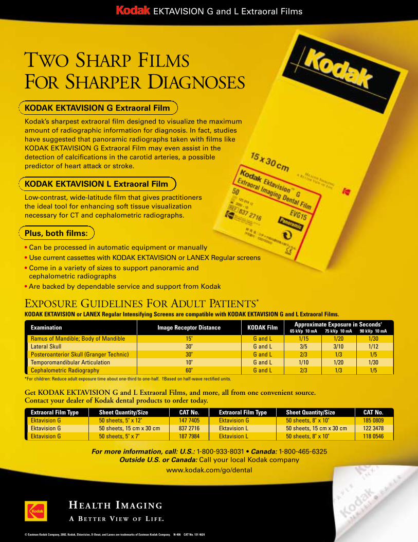
TWO SHARP FILMSFOR SHARPER DIAGNOSESKODAK EKTAVISION G Extraoral Film
Kodak’s sharpest extraoral film designed to visualize the maximum amount of radiographic information for diagnosis. In fact, studies have suggested that panoramic radiographs taken with films like KODAK EKTAVISION G Extraoral Film may even assist in the detection of calcifications in the carotid arteries, a possible predictor of heart attack or stroke.
KODAK EKTAVISION L Extraoral Film
Low-contrast, wide-latitude film that gives practitioners the ideal tool for enhancing soft tissue visualization necessary for CT and cephalometric radiographs.
Plus, both films:
• Can be processed in automatic equipment or manually
• Use current cassettes with KODAK EKTAVISION or LANEX Regular screens
• Come in a variety of sizes to support panoramic and cephalometric radiographs
• Are backed by dependable service and support from Kodak
For more information, call: U.S.: 1-800-933-8031 • Canada: 1-800-465-6325Outside U.S. or Canada: Call your local Kodak company
www.kodak.com/go/dental
*For children: Reduce adult exposure time about one-third to one-half. †Based on half-wave rectified units.
EXPOSURE GUIDELINES FOR ADULT PATIENTS*
Examination Image Receptor Distance KODAK Film Approximate Exposure in Seconds†
65 kVp 10 mA 75 kVp 10 mA 90 kVp 10 mA
Ramus of Mandible; Body of Mandible 15" G and L 1/15 1/20 1/30Lateral Skull 30" G and L 3/5 3/10 1/12Posteroanterior Skull (Granger Technic) 30" G and L 2/3 1/3 1/5Temporomandibular Articulation 10" G and L 1/10 1/20 1/30Cephalometric Radiography 60" G and L 2/3 1/3 1/5
Get KODAK EKTAVISION G and L Extraoral Films, and more, all from one convenient source. Contact your dealer of Kodak dental products to order today.
Extraoral Film Type Sheet Quantity/Size CAT No. Extraoral Film Type Sheet Quantity/Size CAT No.Ektavision G 50 sheets, 5" x 12" 147 7405 Ektavision G 50 sheets, 8" x 10" 185 0809Ektavision G 50 sheets, 15 cm x 30 cm 837 2716 Ektavision L 50 sheets, 15 cm x 30 cm 122 3478Ektavision G 50 sheets, 5" x 7" 187 7984 Ektavision L 50 sheets, 8" x 10" 118 0546
KODAK EKTAVISION or LANEX Regular Intensifying Screens are compatible with KODAK EKTAVISION G and L Extraoral Films.
Top Related