


Languages
Pages
Legal


Robotics 1
Wheeled Mobile Robots Introduction and Kinematic Modeling
Prof. Alessandro De Luca
Robotics 1 1

Summary
introduction Wheeled Mobile Robot (WMR) operating environments basic motion problem elementary tasks block diagram of a mobile robot
kinematic modeling configuration space wheel types nonholonomic constraints (due to wheel rolling) kinematic model of WMR
examples of kinematic models unicycle car-like
Robotics 1 2

Wheeled mobile robots
locally restricted mobility NONHOLONOMIC constraints
SuperMARIO & MagellanPro (DIS, Roma)
Hilare 2-Bis (LAAS, Toulouse) with “off-hooked” trailer
Robotics 1 3

Wheeled mobile robots
Tribolo Omni-2
full mobility OMNIDIRECTIONAL robots
Robotics 1 4

Video
SuperMARIO Omni-2
Robotics 1 5

Operating environments
external 3D unstructured
natural vs. artificial landmarks
internal 2D known
availability of a map (possibly acquired by robot sensors in an exploratory phase)
unknown with static or dynamic obstacles
Robotics 1 6

high computational complexity of the planning problem dynamic environment (including multiple robots) restricted mobility of robotic vehicle
analysis of elementary tasks
Basic motion problem
start
goal static
obstacles
dynamic obstacle
Robotics 1 7

Multi-robot environment
5 robots in simultaneous motion
2 Pioneer 1 Nomad XR-400
2 Hilare with on-board
manipulator arm
Robotics 1 8

Elementary motion tasks
point-to-point motion in the configuration space
path following trajectory tracking
geometric path + timing law
purely reactive (local) motion
mixed situations of planning and control
Robotics 1 9

point-to-point motion (e.g., parking)
Elementary motion tasks (cont’d)
initial configuration
final configuration
d path
reference WMR (“closest” on path)
parameter s
ep
time t reference WMR (at instant t)
trajectory
path following
trajectory tracking
Robotics 1 10
Elementary motion tasks (cont’d)
detected obstacle
sensor range
goal
planned path
executed path
unknown obstacle
wall following
examples of reactive motion
on-line obstacle avoidance
target tracking
Robotics 1 11

Block diagram of a mobile robot
actuators (A) DC motors with reduction task output (even identity, i.e., q)
effectors (E) on-board manipulator, gripper, … sensors
proprioceptive: encoders, gyroscope, … exteroceptive: bumpers, rangefinders (IR = infrared, US = ultrasound),
structured light (laser+CCD), vision (mono, stereo, color, …) control
high- / low-level feedforward (from planning) / feedback
task
planning control A mobile robot
E
environment
sensors (proprio/extero)
+ - task
output
Robotics 1 12

Block diagram of a mobile robot (cont’d)
WMR + encoders -
+ high- level
control
low-level control: analog velocity PI(D) loop with high gain (or digital, at high frequency)
WMR kinematic
model -
high- level
control +
planning
high-level control: purely kinematics-based, with velocity commands
task output
A low- level
controls
Robotics 1 13

Configuration space for wheeled mobile robots
rigid body (one, or many interconnected) pose of one body is given by a set of INDEPENDENT variables
# total of descriptive variables (including all bodies) - # total of HOLONOMIC (positional) constraints # generalized coordinates
wheels (of different types) in contact with the ground (possibly) additional INTERNAL variables
configuration space C parameterized through
dim C =
Robotics 1 14

Examples of configuration spaces
y
x
ϑ
y
x
ϑ
φ
y
x
ϑ
φ
δ
dim C = 3
dim C = 4
dim C = 5
Robotics 1 15

Additional configuration variables
in all previous cases, one can add in the parameterization of C also the rolling angle of each wheel
rψ
ψ
Robotics 1 16

Types of wheels
conventional
fixed
centered steering
off-centered steering (castor)
omni-directional (Mecanum/Swedish wheels)
tv
tv
dtv
0=nv
tv
nvRobotics 1 17

pure rolling constraints each wheel rolls on the ground without slipping (longitudinally) nor
skidding (sideways)
continuous contact used in dead-reckoning (odometry)
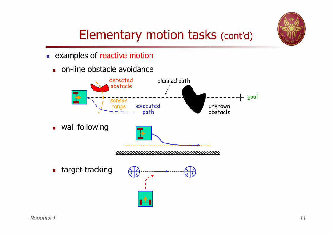
geometric consequence there is always an Instantaneous Center of Rotation (=ICR) where all wheel axes intercept: one ICR for each chassis (= rigid body) constituting the WMR
Differential constraints
Robotics 1 18
Instantaneous Center of Rotation
ICR: a graphical construction
input
computing in sequence (with some trigonometry):
Robotics 1 19

Nonholonomy
from constraints … for each wheel, condition can be written in terms of
generalized coordinates and their derivatives
for N wheels, in matrix form
N differential constraints (in Pfaffian form = linear in velocity)
partially or completely integrable into
not integrable
NONHOLONOMY
reduction of C (dim - ) but
Robotics 1 20

Nonholonomy (cont’d)
… to feasible motion
nonintegrable (nonholonomic)
ALL feasible motion directions can be generated as
being
“ the image of the columns of matrix G coincides with the kernel of matrix A ”
Robotics 1 21
Nonholonomy (cont’d)
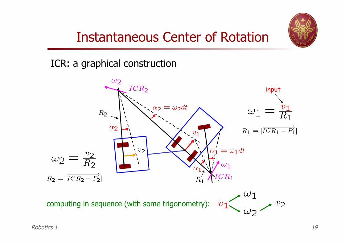
a comparison …
dim C = 3
the space of feasible velocities has dimension 3 and coincides with the tangent space
to the robot configuration space
fixed-base manipulator
same number of commands and generalized velocities
Robotics 1 22

Nonholonomy (cont’d)
wheeled mobile robot
dim C = 3
path on (x,y) plane (with varying orientation)
⊂
less number of commands than generalized velocities!
the space of feasible velocities has here dimension 2 (a subspace of the tangent space)
Robotics 1 23

Kinematic model of WMR provides all feasible directions of instantaneous motion describes the relation between the velocity input commands and
the derivatives of generalized coordinates (a differential model!)
needed for studying the accessibility of (i.e., the system “controllability”) planning of feasible paths/trajectories design of motion control algorithms incremental WMR localization (odometry) simulation …
configuration space (input) command space
with
Robotics 1 24

Unicycle (ideal)
the choice of a base in the kernel of can be made according to physical considerations on the real system
Robotics 1 25

Unicycle (real)
a) three centered steering wheels [Nomad 200]
synchro-drive (2 motors)
1 = linear speed 2 = angular speed
of the robot
Robotics 1 26

Unicycle (real)
b) two fixed wheels + castor [SuperMARIO, MagellanPro]
castor
linear speed of the two fixed wheels on the ground
(R = right, L = left)
note: d is here the half-axis length (in textbook, it is the entire distance between the two fixed wheels!!)
Robotics 1 27

Equivalence of the two models
a) b) by means of a transformation (invertible and constant) between inputs
…however, pay attention to how possible (equal) bounds on maximum speed of the two wheels are transformed!
here
Robotics 1 28
⇔
⇔
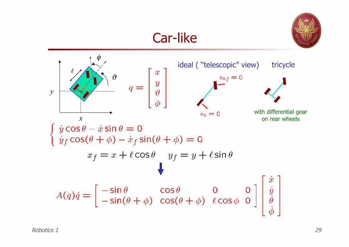
Car-like
y
x
ϑ
φideal ( “telescopic” view) tricycle
with differential gear on rear wheels
Robotics 1 29

Car-like (continued)
FD = Front wheel Drive
kinematic model of unicycle with trailer (e.g., Hilare 2-bis)
linear and angular speed of front wheel ( )
Robotics 1 30

Car-like (continued)
RD = Rear wheel Drive
singularity at
linear speed of rear wheel
(medium point of rear-axis)
(the model is no longer valid)
( )
Robotics 1 31

a) f = fixed or centered s = steerable
General constraint form by wheel type
y
x
constant (f) or variable (s)
Robotics 1 32

b) o = steerable with off-set (off-centered)
y
x
d
variable
General constraint form by wheel type
Robotics 1 33

5 possible classes for the WMR kinematic model (single chassis)
Possible kinematic “classes”
on same axis
I
II
class description example (N = 3)
number of wheels
is an omnidirectional WMR!
= 3
= 2 = 1
Robotics 1 34

Example of class I WMR (omnidirectional)
with three conventional off-centered wheels, independently actuated
Robotics 1 35

III synchronized if > 1
on same axis
at least one out of the common axis of the two fixed wheels
synchronized if > 2
Possible kinematic “classes” (cont’d)
WMRs in same class are characterized by same “maneuverability” previous models of WMRs fit indeed in this classification: SuperMARIO
(class II), Nomad 200 (class III), car-like (class IV)
IV
V = 1 = 2
= 1
= 1 = 2
= 2
Robotics 1 36
Top Related