


Languages
Pages
Legal


Keysight 16451B Dielectric Test Fixture
Operation and Service Manual


○C Copyright 2008 Keysight Technologies
Keysight 16451B DIELECTRIC MATERIAL TEST FIXTURE Operation Manual
Manual Change Keysight Part No. N/A
June 2008
Change 1 Following note is added on the following designated locations.
NOTE
Be careful not to contaminate or not to make a scratch on the surface of the electrode. A scratch or contamination of
the electrode’s surface sometimes prevents the measured capacitance from falling within the limits shown in
“Electrode Adjustment” (Page 3-36). If it happens, replace the scratched/contaminated electrode or contact your
nearest Keysight Technologies Sales and Service Office. As long as the measured capacitance falls within the limits,
the electrode doesn’t need to be replaced or repaired.
Locations:
1. Page 3-29
2. Page 3-37
3. Page 3-41
4. Page 3-44
5. Page 4-8
Change 2 Correct Table 1-2 (Page1-4) as follows.
Compatible Instrument Model Measurement Frequency Range
4192A LF Impedance Analyzer 5 Hz - 13 MHz 4194A Impedance/Gain-Phase Analyzer 100 Hz - 40 MHz*1
4263B LCR Meter 100Hz - 100kHz 4268A 120Hz/1kHz Capacitance Meter 120Hz/1kHz 4278A 1 kHz/1 MHz Capacitance Meter 1 kHz/1 MHz
4279A 1 MHz C-V Meter 1 MHz 4284A Precision LCR Meter 20 Hz - 1 MHz 4285A Precision LCR Meter 75kHz - 30MHz
4288A 1 kHz/1 MHz Capacitance Meter 1 kHz/1 MHz 4294A Precision Impedance Analyzer 40Hz - 110MHz*2
E4980A Precision LCR Meter 20 Hz – 20 MHz
Change 3 Correct the note for table 1-2 in page 1-4.
*1: The upper frequency of the 4194A is 40 MHz but it is limited to 30 MHz when used with the 16451B.
*2: The upper frequency of the 4294A is 110 MHz but it is limited to 30 MHz when used with the 16451B.
○C Copyright 2008 Keysight Technologies
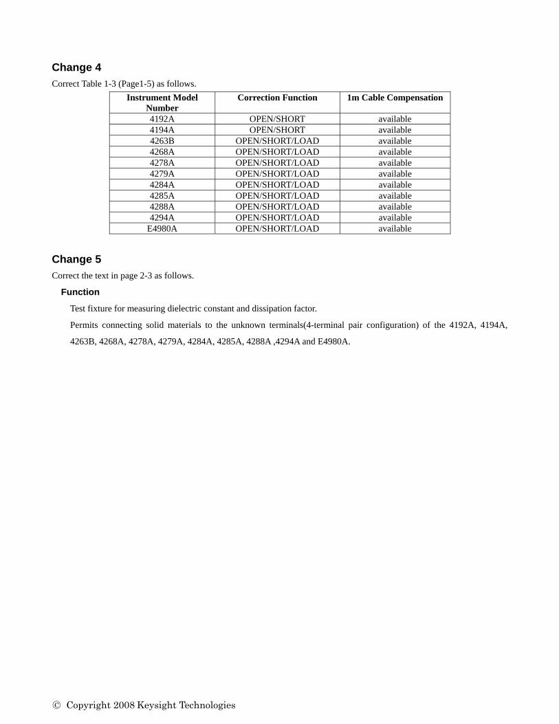
Change 4 Correct Table 1-3 (Page1-5) as follows.
Instrument Model Number
Correction Function 1m Cable Compensation
4192A OPEN/SHORT available 4194A OPEN/SHORT available 4263B OPEN/SHORT/LOAD available 4268A OPEN/SHORT/LOAD available 4278A OPEN/SHORT/LOAD available 4279A OPEN/SHORT/LOAD available 4284A OPEN/SHORT/LOAD available 4285A OPEN/SHORT/LOAD available 4288A OPEN/SHORT/LOAD available 4294A OPEN/SHORT/LOAD available
E4980A OPEN/SHORT/LOAD available
Change 5 Correct the text in page 2-3 as follows.
Function
Test fixture for measuring dielectric constant and dissipation factor.
Permits connecting solid materials to the unknown terminals(4-terminal pair configuration) of the 4192A, 4194A,
4263B, 4268A, 4278A, 4279A, 4284A, 4285A, 4288A ,4294A and E4980A.

○C Copyright 2008 Keysight Technologies
Change 6 Replace the contents of page 2-4 by the following,
Dissipation Factor Accuracy (Δ tan δ)
The surfaces of material are assumed to be ideally parallel, flat and smooth.
The above equation is only compatible for electrodes A and B.
[m]

○C Copyright 2008 Keysight Technologies
Change 7 Correct the sentence at “16451B Overview” in page 3-1.
The 16451B is a test fixture for measuring disc and lm dielectric materials when connected to Keysight’s LCR meters
or impedance analyzers, and is usable up to 30 MHz.
Change 8 Correct the sentence of step 8.in Page 3-43.
Keep pressing the Guarded/Guard electrode pressure adjuster shown in Figure 3-25 and turn the three screws in a
clockwise sequence until the measured capacitance value is within the limits listed in Table 3-5.

○C Copyright 2008 Keysight Technologies
Keysight 16451B DIELECTRIC MATERIAL TEST FIXTURE Operation Manual
マニュアル チェンジ
Keysight Part No. N/A
June 2008
変更 1
下記脚注を以下に指定するページに追加してください。
記:
電極の表面は汚したりキズをつけることのないよう取り扱いには十分注意してください。電極表面上の汚れやキズ
によって容量を測定する際、“電極の調節” (Page 3-33) で提示されるリミットの範囲に収まらない可能性が発生し
ます。
このような状況が発生した場合には電極を交換するかお近くのアジレントテクノロジーの営業、もしくはサービスまで
お問い合わせください。
容量を測定した際、その測定結果がリミットに収まっている場合には、電極を交換する必要はありません。
追加箇所:
1. Page 3-26
2. Page 3-33 電極の平行度の粗調節の項の前
3. Page 3-37 電極水平置きの微調節の項の前
4. Page 3-39
5. Page 4-8
変更 2
1-4 ページの 表 1-2 を以下の表に差し替えてください。
適合測定機器 測定周波数
4192A LF Impedance Analyzer 5 Hz - 13 MHz 4194A Impedance/Gain-Phase Analyzer 100 Hz - 40 MHz*1
4263B LCR Meter 100Hz - 100kHz 4268A 120Hz/1kHz Capacitance Meter 120Hz/1kHz 4278A 1 kHz/1 MHz Capacitance Meter 1 kHz/1 MHz
4279A 1 MHz C-V Meter 1 MHz 4284A Precision LCR Meter 20 Hz - 1 MHz 4285A Precision LCR Meter 75kHz - 30MHz
4288A 1 kHz/1 MHz Capacitance Meter 1 kHz/1 MHz 4294A Precision Impedance Analyzer 40Hz - 110MHz*2
E4980A Precision LCR Meter 20 Hz – 20 MHz

○C Copyright 2008 Keysight Technologies
変更 3
1-4 ページの表 1-2 の脚注を下記に変更してください。
*1: 16451B を使用する際の 4194A の測定周波数の上限は、30 MHz となります。
*2: 16451B を使用する際の 4294A の測定周波数の上限は、30 MHz となります。
変更 4
1-5 ページの 表 1-3 を以下の表に差し替えてください。
Instrument Model Number
Correction Function 1m Cable Compensation
4192A OPEN/SHORT available 4194A OPEN/SHORT available 4263B OPEN/SHORT/LOAD available 4268A OPEN/SHORT/LOAD available 4278A OPEN/SHORT/LOAD available 4279A OPEN/SHORT/LOAD available 4284A OPEN/SHORT/LOAD available 4285A OPEN/SHORT/LOAD available 4288A OPEN/SHORT/LOAD available 4294A OPEN/SHORT/LOAD available
E4980A OPEN/SHORT/LOAD available
変更 5
2-3 ページ 下記箇所を下記文章に変更してください。
機能:
誘電率および誘電正接測定用テストフィクスチャ
4192A, 4194A, 4263B, 4268A, 4278A, 4279A, 4284A, 4285A, 4288A, 4294A and E4980A の測定端子(4 端子対構
成)に固体試料を接続することを可能とする。
周波数範囲:≦ 30 MHz
変更 6
6-1: 2-7 ページの表2-1を下記に変更してください。
使用主電極 試料直径 試料厚さ 主電極直径
A Φ40 ~ 56 mm ≦ 10 mm Φ38 mm
B Φ10 ~ 56 mm ≦ 10 mm Φ5 mm
C Φ56 mm ≦ 10 mm*1 Φ5 ~ 50 mm*2
D Φ20 ~ 56 mm ≦ 10 mm*1 Φ5 ~ 14 mm*2
*1: 薄膜電極厚を含む
*2: 薄膜電極直径

○C Copyright 2008 Keysight Technologies
6-2: 2-4 ページ 測定確度の項に下記を追加してください。
電極 A と電極 B だけに対応する確度を表す。
被測定材料の両面が理想的に平行・平坦で滑らかであることを前提とする。
○C Copyright 2008 Keysight Technologies

○C Copyright 2008 Keysight Technologies
4294A の設定条件
1. 信号レベル: 500 mV
2. BW: 5
3. ケーブル長: 1m
4. 補正: オープン/ショート/ロード
変更 7
3 章 16451B の概要のテキストを以下に変更してください。
16451B の概要
16451B は、Keysight 製 LCR メータやインピーダンス・アナライザに接続して、板状およびフィルム状の誘電材料を
測 定するためのテスト・フィクスチャで 高 30MHz までの周波数で使用できます。
16451B はフィクスチャ・アセンブリと 4 種の交換可能はガード付主電極、および誤差補正用治具によって構成されて
います。図3-1は 16451B のフィクスチャ・アセンブリを、図3-2は 16451B に付属しているアクセサリを示していま
す。


MANUAL CHANGES
Keysight 16451BDIELECTRIC TEST FIXTURE
Operation and Service Manual
MANUAL IDENTIFICATIONModel Number: 16451BDate Printed: Oct. 2000Part Number: 16451-90020
This supplement contains information for correcting manual errors and for adapting the manual to newer instruments that containsimprovements or modifications not documented in the existing manual.
To use this supplement1. Make all ERRATA corrections2. Make all appropriate serial-number-related changes listed below
SERIAL PREFIX OR NUMBER MAKE MANUAL CHANGES2916J 1
JP1KH 2
� New Item
SERIAL PREFIX OR NUMBER MAKE MANUAL CHANGES
CHANGES 1
Correct the Part Number as follows:
Page 4-3, Table 4-1. Replaceable Parts List (1 of 5)
ReferenceDesignator
Part Number Qty Description
8 16451-25010 1 Insulator
CHANGES 2
Change the Part Number as follows:
Page 4-3, Table 4-1. Replaceable Parts List (1 of 5)
ReferenceDesignator
Part Number Qty Description
8 16451-25025 1 Insulator9 16451-24018 1 Plate
Page 4-4, Table 4-2. Replaceable Parts List (2 of 5)
ReferenceDesignator
Part Number Qty Description
1 16451-04013 1 Cover Bottom
NOTEManual change supplement are revised as often as necessary to keep manuals as current and accurate as possible. KeysightTechnologies recommends that you periodically request the latest edition of this supplement. Free copies are available from all KeysightTechnologies offices. When requesting copies, quote the manual identification information from your supplement, or the model number and print date from the title page of the manual.
Date/Div: October, 2000/33Page 1 of 2PRINTED IN JAPAN
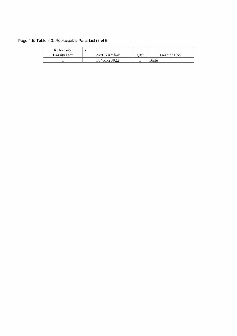
Page 4-5, Table 4-3. Replaceable Parts List (3 of 5)
ReferenceDesignator
Part Number Qty Description
1 16451-20022 1 Base


Notice The information contained in this document is subject to change
without notice.
This document contains proprietary information which is protected by
copyright. All rights are reserved. No part of this document may be
photocopied, reproduced, or translated to another language without
the prior written consent of the Agilent Technologies.
Agilent Technologies Japan, Ltd.
Component Test PGU-Kobe
1-3-2, Murotani, Nishi-ku, Kobe-shi,
Hyogo, 651-2241 Japan
c Copyright 1989, 1992, 1993, 1999, 2000
Agilent Technologies Japan, Ltd.

Manual PrintingHistory
The manual printing date and part number indicate its current
edition. The printing date changes when a new edition is printed.
(Minor corrections and updates which are incorporated at reprint do
not cause the date to change.) The manual part number changes when
extensive technical changes are incorporated.
December 1989 : : : : : : : : : : : First Edition (part number: 16451-90000)
May 1992 : : : : : : : : : : : : : : : Second Edition (part number: 16451-90000)
December 1993 : : : : : : : : : : :Third Edition (part number: 16451-90010)
December 1999 : : : : : : : : : Fourth Edition (part number: 16451-90010)
October 2000 : : : : : : : : : : : : : Fifth Edition (part number: 16451-90020)
iii

Safety Summary The following general safety precautions must be observed during
all phases of operation, service, and repair of this �xture. Failure
to comply with these precautions or with speci�c WARNINGS
given elsewhere in this manual violates safety standards of design,
manufacture, and intended use of the �xture.
The Agilent Technologies assumes no liability for the customer's
failure to comply with these requirements.
DO NOT Operate In An
Explosive Atmosphere
Do not operate the �xture in the presence of ammable gasses or
fumes. Operation of any electrical instrument in such an environment
constitutes a safety hazard.
DO NOT Substitute
Parts Or Modify
Instrument
Because of the danger of introducing additional hazards, do not
substitute parts or perform unauthorized modi�cations to the �xture.
Return the �xture to a Agilent Technologies Sales and Service O�ce
for service and repair to ensure the safety features are maintained.
Dangerous Procedure
Warnings
Warnings, such as the example below, precede potentially dangerous
procedures throughout this manual. Instructions contained in the
warnings must be followed.
Warning Dangerous voltages, capable of causing death, are present inthis �xture. Use extreme caution when handling, testing, andadjusting this �xture.
Safety Symbols General de�nitions of safety symbols used on equipment or in
manuals.
Warning denotes a hazard. It calls attention to a
procedure, practice, condition or the like, which, if
not correctly performed or adhered to, could result in
injury or death to personnel.
Caution sign denotes a hazard. It calls attention to a
procedure, practice, condition or the like, which, if
not correctly performed or adhered to, could result
damage to or destruction of part or all of the product.
Note denotes important information. It calls
attention to a procedure, practice, condition or the
like, which is essential to highlight.
iv

How To Use ThisManual
This is the Operation Manual for the 16451B Dielectric Test Fixture,
containing information on installation, con�guration, operation, and
service in the following four chapters and six appendices. After you
receive your 16451B, begin with Chapter 1.
The 16451B is designed to measure a dielectric using Agilent
Technologies's LCR meters or impedance analyzers. For more
information to operate an instrument, refer to the Operation Manual
of your instrument before reading this Operation Manual.
Chapter 1
Installation
This chapter provides, initial inspection, and preparation information
necessary for you to know before you connect the 16451B to an
instrument.
Chapter 2
General Information
This chapter provides speci�cations, supplemental performance
characteristics, and other general information on the 16451B.
Chapter 3
Operation
This chapter provides basic operation procedures with measurement
techniques and practical measurement examples.
Chapter 4
Service
This chapter provides 16451B parts replacement and troubleshooting
information.
Appendix A
Manual Changes
Appendix A contains the Manual Changes and provides information
for using this manual with a 16451B manufactured before this
manual's printing date.
Appendix B
Recommended
Capacitance Range
Appendix B shows the recommended capacitance range of test
materials when using the 16451B.
Appendix C
Error Correction
Procedure
Appendix C shows error correction procedures to perform the
OPEN/SHORT/LOAD correction when using the 16451B with a
compatible instrument.
Appendix D
Sample Program
Appendix D lists a sample ASP (Auto Sequence Program) program for
the 4194A and a BASIC program for the 4284A to get the dielectric
constant.
Appendix E
Bibliography
Appendix E lists the names of reference (standards) for dielectric
constant measurement.
v

TypefaceConventions
Bold Boldface type is used when a term is de�ned.
For example: icons are symbols.
Italics Italic type is used for emphasis and for the
titles of manuals and other publications.
Italic type is also used for keyboard entries
when a name or a variable must be typed in
place of the words in italics. For example:
copy �lename means to type the word copy,
to type a space, and then to type the name of
a �le such as file1.
Computer Computer font is used to represent BASIC
control program examples.
Computer type is also used for on-screen
prompts and messages.
�HARDKEYS� Labeled keys on the �xture front panel are
enclosed in boxes with boldface ��.
NNNNNNNNNNNNNNNNNNNNNNNNNNSOFTKEYS Softkeys located to the right of the display of
an instrument are enclosed inNNNNN.
Warranty This Agilent Technologies �xture is warranted against defects in
material and workmanship for a period if one year from the date
of shipment, except that in the case of certain components listed
in Chapter 1 of this manual, the warranty shall be for the speci�ed
period. During the warranty period, Agilent Technologies will, at its
option, either repair or replace products which prove to be defective.
For warranty service or repair, this product must be returned to
a service facility designated by Agilent Technologies. The buyer
shall prepay shipping charges to Agilent Technologies and Agilent
Technologies shall pay shipping charges to return the product to the
buyer. However, the buyer shall pay all shipping charges, duties, and
taxes for products returned to Agilent Technologies from another
country.
vi

Limitation OfWarranty
The foregoing warranty shall not apply to defects resulting from
improper or inadequate maintenance by the buyer, buyer-supplied
software or interfacing, unauthorized modi�cation or misuse,
operation outside of the environmental speci�cations for the product,
or improper site preparation or maintenance.
No other warranty is expressed or implied. Agilent Technologies
speci�cally disclaims the implied warranties of merchantability and
�tness for a particular purpose.
ExclusiveRemedies
The remedies provided herein are buyer's sole and exclusive
remedies. Agilent Technologies shall not be liable for any direct,
indirect, special, tract, tort, or any other legal theory.
Assistance Product maintenance agreements and other customer assistance
agreements are available for Agilent Technologies products.
For any assistance, contact your nearest Agilent Technologies Sales
and Service O�ce. Address are provided at the back of this manual.
vii


Contents
1. InstallationIntroduction . . . . . . . . . . . . . . . . . . . . . 1-1
Product Description . . . . . . . . . . . . . . . . . 1-1
Initial Inspection . . . . . . . . . . . . . . . . . . . 1-2
Compatible Measurement Instruments . . . . . . . . . 1-4
Error Correction . . . . . . . . . . . . . . . . . . 1-4
2. General InformationIntroduction . . . . . . . . . . . . . . . . . . . . . 2-1
Safety Considerations . . . . . . . . . . . . . . . . . 2-1
Serial Number . . . . . . . . . . . . . . . . . . . . 2-2
Speci�cations . . . . . . . . . . . . . . . . . . . . 2-3
Function . . . . . . . . . . . . . . . . . . . . . . 2-3
Frequency Range . . . . . . . . . . . . . . . . . . 2-3
Applicable Voltage Range . . . . . . . . . . . . . . 2-3
Cable Length (setting) . . . . . . . . . . . . . . . 2-3
Operating Temperature . . . . . . . . . . . . . . . 2-3
Operating Humidity . . . . . . . . . . . . . . . . . 2-3
Weight . . . . . . . . . . . . . . . . . . . . . . . 2-3
Furnished Accessories and Quantity . . . . . . . . . 2-3
Supplemental Performance Characteristics . . . . . . . 2-4
Measurement Accuracy when using contact electrode
method . . . . . . . . . . . . . . . . . . . . . 2-4
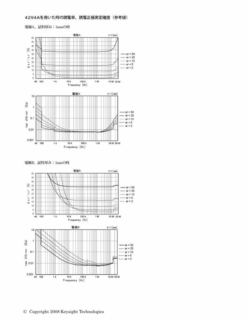
Permittivity Measurement Accuracy including 4294A
(Supplemental Characteristics) . . . . . . . . . 2-5
Electrode Dimensions . . . . . . . . . . . . . . . . 2-7
Guarded/Guard Electrode (4 types, changeable) . . . 2-7
Unguarded Electrode . . . . . . . . . . . . . . . 2-9
Available Test Material Dimensions . . . . . . . . . 2-9
Micrometer Resolution . . . . . . . . . . . . . . . 2-10
Dimensions of Fixture Assembly . . . . . . . . . . . 2-10
Storage and Repacking . . . . . . . . . . . . . . . . 2-11
Environmental Requirements . . . . . . . . . . . . 2-11
Original Packaging . . . . . . . . . . . . . . . . . 2-11
Other Packaging . . . . . . . . . . . . . . . . . . 2-11
Contents-1
3. OperationIntroduction . . . . . . . . . . . . . . . . . . . . . 3-1
16451B Overview . . . . . . . . . . . . . . . . . . . 3-1
Fixture Assembly . . . . . . . . . . . . . . . . . . 3-1
Furnished Accessories . . . . . . . . . . . . . . . 3-4
Dielectric Measurement Basic . . . . . . . . . . . . . 3-6
Basic theory . . . . . . . . . . . . . . . . . . . . 3-6
Guard Electrode . . . . . . . . . . . . . . . . . . 3-8
Measurement Method . . . . . . . . . . . . . . . . . 3-9
Contacting Electrode Method (used with
Rigid Metal Electrode) . . . . . . . . . . . . . . 3-11
Principle . . . . . . . . . . . . . . . . . . . . . 3-11
Electrodes of the 16451B . . . . . . . . . . . . . 3-13
Applicable Size of Test Material for Electrode-A
(38 mm Guarded/Guard Electrode) . . . . . . . 3-14
Applicable Size of Test Material for Electrode-B
(5 mm Guarded/Guard Electrode) . . . . . . . . 3-15
Contacting Electrode Method (used with
Thin Film Electrode) . . . . . . . . . . . . . . 3-16
Principle . . . . . . . . . . . . . . . . . . . . . 3-16
Thin Film Electrode . . . . . . . . . . . . . . . 3-17
Electrodes of the 16451B . . . . . . . . . . . . . 3-18
Applicable Size of Test Material for Electrode-C
(Guarded/Guard Electrode for Large Thin Film
Electrode) . . . . . . . . . . . . . . . . . . 3-19
Applicable Size of Test Material Electrode-D
(Guarded/Guard Electrode for Small Thin Film
Electrodes) . . . . . . . . . . . . . . . . . . 3-20
Non-contacting Electrode Method (Air Gap Method) . 3-21
Principle . . . . . . . . . . . . . . . . . . . . . 3-21
Electrodes of the 16451B . . . . . . . . . . . . . 3-23
Applicable Size of Test Material for Electrode-A
(38 mm Guarded/Guard Electrode) . . . . . . . 3-24
Applicable Size of Test Material for Electrode-B
(5 mm Guarded/Guard Electrode) . . . . . . . . 3-25
Preparation of Test Material . . . . . . . . . . . . . . 3-26
Shape and Size of Test Material . . . . . . . . . . . 3-26
Thickness of Test Material . . . . . . . . . . . . . . 3-26
Flatness of Test Material's Surface . . . . . . . . . . 3-27
Thin Film Electrode . . . . . . . . . . . . . . . . 3-27
Connecting to the Instrument . . . . . . . . . . . . . 3-28
Changing the Guarded/Guard Electrode . . . . . . . . 3-28
Error Correction . . . . . . . . . . . . . . . . . . . 3-30
Open Correction (ZERO OPEN O�set Adjustment) . . . 3-30
Short Correction (ZERO SHORT O�set Adjustment) . . 3-32
For Electrode-A and Electrode-B (Rigid Metal
Electrode) . . . . . . . . . . . . . . . . . . 3-32
For Electrode-C and Electrode-D (Electrode for Thin
Film Electrodes) . . . . . . . . . . . . . . . . 3-34
LOAD Correction (LOAD Compensation) . . . . . . . 3-35
Electrode Adjustment . . . . . . . . . . . . . . . . . 3-36
Rough Adjustment to Make Electrodes Parallel . . . . 3-38
Accurate Adjustment to Make Electrodes Parallel . . . 3-40
Accurate Adjustment in Vertical Position . . . . . . 3-40
Accurate Adjustment in Horizontal Position . . . . 3-42
Contents-2
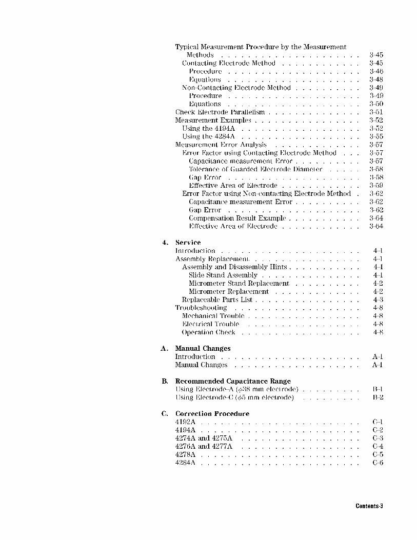
Typical Measurement Procedure by the Measurement
Methods . . . . . . . . . . . . . . . . . . . . . 3-45
Contacting Electrode Method . . . . . . . . . . . . 3-45
Procedure . . . . . . . . . . . . . . . . . . . . 3-46
Equations . . . . . . . . . . . . . . . . . . . . 3-48
Non-Contacting Electrode Method . . . . . . . . . . 3-49
Procedure . . . . . . . . . . . . . . . . . . . . 3-49
Equations . . . . . . . . . . . . . . . . . . . . 3-50
Check Electrode Parallelism . . . . . . . . . . . . . . 3-51
Measurement Examples . . . . . . . . . . . . . . . . 3-52
Using the 4194A . . . . . . . . . . . . . . . . . . 3-52
Using the 4284A . . . . . . . . . . . . . . . . . . 3-55
Measurement Error Analysis . . . . . . . . . . . . . 3-57
Error Factor using Contacting Electrode Method . . . 3-57
Capacitance measurement Error . . . . . . . . . . 3-57
Tolerance of Guarded Electrode Diameter . . . . . 3-58
Gap Error . . . . . . . . . . . . . . . . . . . . 3-58
E�ective Area of Electrode . . . . . . . . . . . . 3-59
Error Factor using Non-contacting Electrode Method . 3-62
Capacitance measurement Error . . . . . . . . . . 3-62
Gap Error . . . . . . . . . . . . . . . . . . . . 3-62
Compensation Result Example . . . . . . . . . . . 3-64
E�ective Area of Electrode . . . . . . . . . . . . 3-64
4. ServiceIntroduction . . . . . . . . . . . . . . . . . . . . . 4-1
Assembly Replacement . . . . . . . . . . . . . . . . 4-1
Assembly and Disassembly Hints . . . . . . . . . . . 4-1
Slide Stand Assembly . . . . . . . . . . . . . . . 4-1
Micrometer Stand Replacement . . . . . . . . . . 4-2
Micrometer Replacement . . . . . . . . . . . . . 4-2
Replaceable Parts List . . . . . . . . . . . . . . . . 4-3
Troubleshooting . . . . . . . . . . . . . . . . . . . 4-8
Mechanical Trouble . . . . . . . . . . . . . . . . . 4-8
Electrical Trouble . . . . . . . . . . . . . . . . . 4-8
Operation Check . . . . . . . . . . . . . . . . . . 4-8
A. Manual ChangesIntroduction . . . . . . . . . . . . . . . . . . . . . A-1
Manual Changes . . . . . . . . . . . . . . . . . . . A-1
B. Recommended Capacitance RangeUsing Electrode-A (�38 mm electrode) . . . . . . . . . B-1
Using Electrode-C (�5 mm electrode) . . . . . . . . . B-2
C. Correction Procedure4192A . . . . . . . . . . . . . . . . . . . . . . . . C-1
4194A . . . . . . . . . . . . . . . . . . . . . . . . C-2
4274A and 4275A . . . . . . . . . . . . . . . . . . C-3
4276A and 4277A . . . . . . . . . . . . . . . . . . C-4
4278A . . . . . . . . . . . . . . . . . . . . . . . . C-5
4284A . . . . . . . . . . . . . . . . . . . . . . . . C-6
Contents-3

D. Sample programSample ASP Program for the 4194A . . . . . . . . . . D-1
Sample Program for the 4284A . . . . . . . . . . . . D-2
E. Bibliography
Index
Contents-4

Figures
1-1. Product Overview . . . . . . . . . . . . . . . . . 1-3
2-1. Serial Number Plate . . . . . . . . . . . . . . . . 2-2
2-2. Electrode A, MUT Thickness: 1mm . . . . . . . . . 2-5
2-3. Electrode B, MUT Thickness: 1mm . . . . . . . . . 2-6
2-4. Dimensions of Electrode-A . . . . . . . . . . . . . 2-7
2-5. Dimensions of Electrode-B . . . . . . . . . . . . . 2-7
2-6. Dimensions of Electrode-C . . . . . . . . . . . . . 2-8
2-7. Dimensions of Electrode-D . . . . . . . . . . . . . 2-8
2-8. Dimensions of Unguarded Electrode . . . . . . . . . 2-9
2-9. Dimensions of Test Fixture Assembly . . . . . . . . 2-10
3-1. Fixture Assembly . . . . . . . . . . . . . . . . . . 3-2
3-2. Furnished Accessories . . . . . . . . . . . . . . . 3-4
3-3. Basic Model for Dielectric Measurement . . . . . . . 3-6
3-4. Capacitance Measurement using Unguarded Electrode
System . . . . . . . . . . . . . . . . . . . . . 3-8
3-5. Capacitance Measurement using Guarded Electrode
System . . . . . . . . . . . . . . . . . . . . . 3-8
3-6. Summary of Measurement Methods . . . . . . . . . 3-10
3-7. Contacting Electrode Method (Rigid Metal Electrode) . 3-11
3-8. Electrode of the 16451B for Contacting Electrode
Method (Rigid Metal Electrode) . . . . . . . . . . 3-13
3-9. Applicable Size of Test Material for Electrode-A . . . 3-14
3-10. Applicable Size of Test Material for Electrode-B . . . 3-15
3-11. Contacting Electrode Method (Thin Film Electrode) . . 3-16
3-12. Electrode of the 16451B for Contacting Electrode
Method (Thin Film Electrode) . . . . . . . . . . 3-18
3-13. Applicable Size of Test Material for Electrode-C . . . 3-19
3-14. Applicable Size of Test Material for Electrode-D . . . 3-20
3-15. Non-contacting method (Air Gap method) . . . . . . 3-21
3-16. Electrode of the 16451B for Non-Contacting Electrode
Method (Air Gap Method) . . . . . . . . . . . . 3-23
3-17. Applicable Size of Test Material for Electrode-A . . . 3-24
3-18. Applicable Size of Test Material for Electrode-B . . . 3-25
3-19. Screw Position to Attach Guarded/Guard Electrode . . 3-28
3-20. Connecting the Attachment to the Guarded/Guard
Electrode for OPEN Correction . . . . . . . . . . 3-30
3-21. OPEN Correction . . . . . . . . . . . . . . . . . . 3-31
3-22. Connecting the Attachment to the Unguarded
Electrode for SHORT Correction . . . . . . . . . 3-32
3-23. SHORT Correction for Rigid Metal Electrode . . . . . 3-33
3-24. SHORT Correction for Thin Film Electrodes . . . . . 3-34
3-25. Vertical Position and Electrode Adjustment Screws . . 3-38
3-26. Rough Adjustment Procedure . . . . . . . . . . . . 3-39
3-27. Vertical Position . . . . . . . . . . . . . . . . . . 3-40
3-28. The Micrometer Scale Adjusted to 0.01 mm . . . . . . 3-41
3-29. Horizontal Position . . . . . . . . . . . . . . . . . 3-42
Contents-5

3-30. Contacting Electrode Method (Rigid Metal Electrode) . 3-46
3-31. Contacting Electrode Method (Thin Film Electrode) . . 3-46
3-32. Non-Contacting Electrode Method (Air Gap Method) . 3-49
3-33. Sample Result of Cp-D Measurement Using the 4194A 3-54
3-34. Sample Result of Dielectric Constant Using the 4194A 3-54
3-35. Airgap E�ects . . . . . . . . . . . . . . . . . . . 3-59
4-1. Slide Stand Assembly . . . . . . . . . . . . . . . . 4-1
4-2. Micrometer Stand Replacement . . . . . . . . . . . 4-2
4-3. Micrometer Replacement . . . . . . . . . . . . . . 4-2
4-4. Cable Connection Diagram . . . . . . . . . . . . . 4-9
B-1. Recommended Capacitance Range Using Electrode-A . B-1
B-2. Recommended Capacitance Range Using Electrode-B . B-2
Contents-6
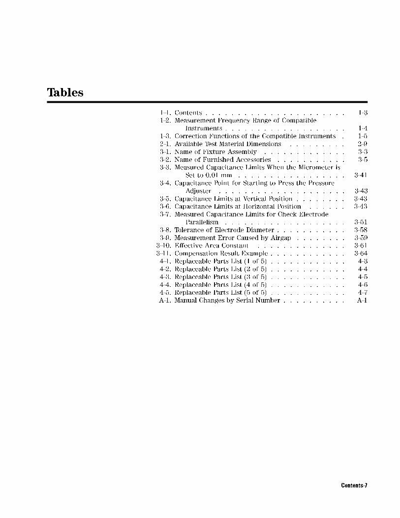
Tables
1-1. Contents . . . . . . . . . . . . . . . . . . . . . . 1-3
1-2. Measurement Frequency Range of Compatible
Instruments . . . . . . . . . . . . . . . . . . . 1-4
1-3. Correction Functions of the Compatible Instruments . 1-5
2-1. Available Test Material Dimensions . . . . . . . . . 2-9
3-1. Name of Fixture Assembly . . . . . . . . . . . . . 3-3
3-2. Name of Furnished Accessories . . . . . . . . . . . 3-5
3-3. Measured Capacitance Limits When the Micrometer is
Set to 0.01 mm . . . . . . . . . . . . . . . . . 3-41
3-4. Capacitance Point for Starting to Press the Pressure
Adjuster . . . . . . . . . . . . . . . . . . . . 3-43
3-5. Capacitance Limits at Vertical Position . . . . . . . . 3-43
3-6. Capacitance Limits at Horizontal Position . . . . . . 3-43
3-7. Measured Capacitance Limits for Check Electrode
Parallelism . . . . . . . . . . . . . . . . . . . 3-51
3-8. Tolerance of Electrode Diameter . . . . . . . . . . . 3-58
3-9. Measurement Error Caused by Airgap . . . . . . . . 3-59
3-10. E�ective Area Constant . . . . . . . . . . . . . . 3-61
3-11. Compensation Result Example . . . . . . . . . . . . 3-64
4-1. Replaceable Parts List (1 of 5) . . . . . . . . . . . . 4-3
4-2. Replaceable Parts List (2 of 5) . . . . . . . . . . . . 4-4
4-3. Replaceable Parts List (3 of 5) . . . . . . . . . . . . 4-5
4-4. Replaceable Parts List (4 of 5) . . . . . . . . . . . . 4-6
4-5. Replaceable Parts List (5 of 5) . . . . . . . . . . . . 4-7
A-1. Manual Changes by Serial Number . . . . . . . . . . A-1
Contents-7


1
Installation
Introduction This chapter provides the information necessary for receiving and
performing an incoming inspection, and preparing the 16451B for use.
The WARNINGs, CAUTIONs, and NOTEs given throughout this
document must be carefully followed to ensure the operator's safety
and to not damage the 16451B.
ProductDescription
The 16451B is a Dielectric Test Fixture used with LCR meters and
impedance analyzers for accurate measurement of insulating and
dielectric materials. The 16451B can be used with LCR meters and
impedance analyzers which use the 4-terminal pair measurement
con�guration.
Installation 1-1

Initial Inspection This �xture has been carefully inspected electrically and mechanically
before being shipped from the factory. It should be in perfect
condition, no scratches, dents or the like, and it should be in perfect
electrical condition. Verify this by carefully performing an incoming
inspection to check the �xture for signs of physical damage and
missing contents. If any discrepancy is found, notify the carrier
and Agilent Technologies. Your Agilent Technologiessales o�ce will
arrange for repair and replacement without waiting for the claim to
be settled.
1. Inspect the shipping container for damage, and keep the shipping
materials until the inspection is completed.
2. Verify that the shipping container contains everything shown in
Figure 1-1 and listed in Table 1-1 of this Operation and Service
Manual.
3. Inspect the exterior of the 16451B for any signs of damage.
The Electrode-A (38 mm electrode) and the Unguarded electrode are
installed on the test �xture when the 16451B is shipped from the
factory.
1-2 Installation

Figure 1-1. Product Overview
Table 1-1. Contents
No. Description Agilent Part Number QTY
(1) Test Fixture PN 16451-61001 1
(with Electrode-A, Unguarded electrode and covers)
(2) Electrode-B and cover PN 16451-60013 1
(3) Electrode-C and cover PN 16451-60012 1
(4) Electrode-D and cover PN 16451-60014 1
(5) Attachment for error compensation and cover PN 16451-60021 1
(6) Hex key (for replacing electrodes) PN 8710-1181 1
(7) Carrying Case PN 16451-60001 1
The Electrode-A and the Unguarded electrode are installed on the test
�xture when the 16451B is shipped from the factory.
Installation 1-3
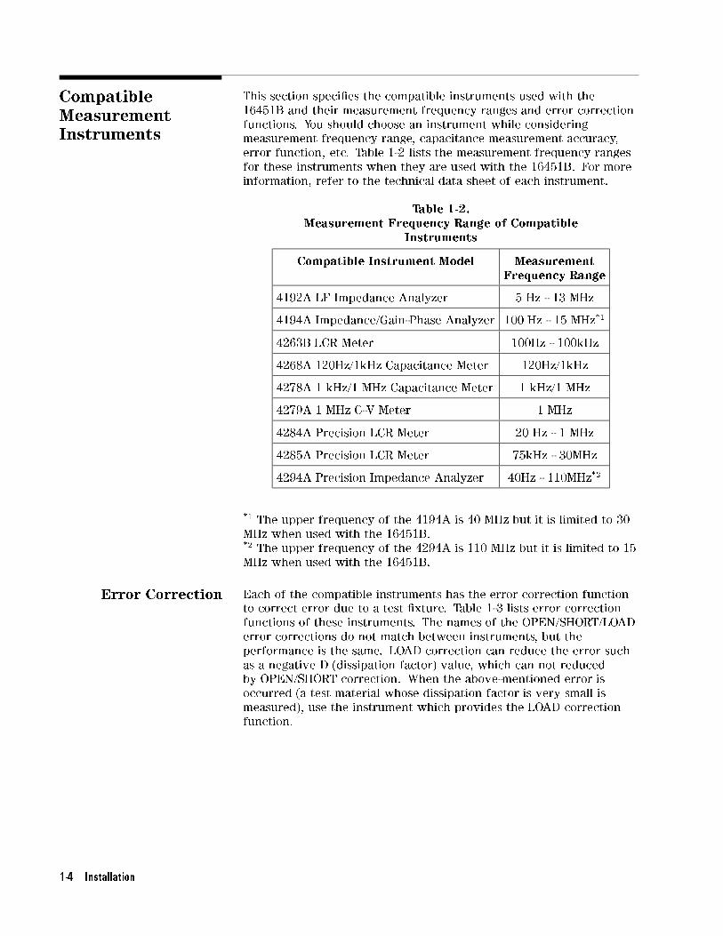
CompatibleMeasurementInstruments
This section speci�es the compatible instruments used with the
16451B and their measurement frequency ranges and error correction
functions. You should choose an instrument while considering
measurement frequency range, capacitance measurement accuracy,
error function, etc. Table 1-2 lists the measurement frequency ranges
for these instruments when they are used with the 16451B. For more
information, refer to the technical data sheet of each instrument.
Table 1-2.Measurement Frequency Range of Compatible
Instruments
Compatible Instrument Model MeasurementFrequency Range
4192A LF Impedance Analyzer 5 Hz - 13 MHz
4194A Impedance/Gain-Phase Analyzer 100 Hz - 15 MHz*1
4263B LCR Meter 100Hz - 100kHz
4268A 120Hz/1kHz Capacitance Meter 120Hz/1kHz
4278A 1 kHz/1 MHz Capacitance Meter 1 kHz/1 MHz
4279A 1 MHz C-V Meter 1 MHz
4284A Precision LCR Meter 20 Hz - 1 MHz
4285A Precision LCR Meter 75kHz - 30MHz
4294A Precision Impedance Analyzer 40Hz - 110MHz*2
*1 The upper frequency of the 4194A is 40 MHz but it is limited to 30
MHz when used with the 16451B.*2 The upper frequency of the 4294A is 110 MHz but it is limited to 15
MHz when used with the 16451B.
Error Correction Each of the compatible instruments has the error correction function
to correct error due to a test �xture. Table 1-3 lists error correction
functions of these instruments. The names of the OPEN/SHORT/LOAD
error corrections do not match between instruments, but the
performance is the same. LOAD correction can reduce the error such
as a negative D (dissipation factor) value, which can not reduced
by OPEN/SHORT correction. When the above-mentioned error is
occurred (a test material whose dissipation factor is very small is
measured), use the instrument which provides the LOAD correction
function.
1-4 Installation

Table 1-3.Correction Functions of the Compatible Instruments
InstrumentModel Number
CorrectionFunction
1 m CableCompensation
4192A OPEN/SHORT available
4194A OPEN/SHORT available
4263B OPEN/SHORT/LOAD available
4268A OPEN/SHORT/LOAD available
4278A OPEN/SHORT/LOAD*1 available
4279A OPEN/SHORT/LOAD available
4284A OPEN/SHORT/LOAD*1 available
4285A OPEN/SHORT/LOAD available
4294A OPEN/SHORT/LOAD available
*1 A working standard is required to perform the LOAD
compensation.
Installation 1-5


2
General Information
Introduction This chapter describes safety consideration, serial number,
speci�cations, supplemental performance characteristics, and
information on storing and repacking the 16451B.
Note In this manual, the term dielectric constant means \relativedielectric constant". In common usage the word \relative" is
frequently dropped. The term \dielectric constant" is often called
\permittivity" in other documents. This manual will unify it to
\dielectric constant".
SafetyConsiderations
The 16451B conforms to the safety requirements of an IEC
(International Electrotechnical Commission) Publication-348 (1971)
Safety Class 1 instrument and is shipped from the factory in a safe
condition.
General Information 2-1

Serial Number A serial number is stamped on the serial number plate, as shown
in Figure 2-1, attached to the 16451B. The serial number used by
Agilent Technologies consists of ten characters. The characters are
separated into two sections. The �rst four digits and a letter are the
serial number pre�x, and the last �ve digits are the su�x. The pre�x
is the same for all identical 16451B's; it changes only when a change
is made to the 16451B. The letter placed between the two sections
identi�es the country where the 16451B was manufactured. The
su�x is assigned sequentially and is di�erent for each 16451B.
Figure 2-1. Serial Number Plate
The contents of this manual applies to 16451B's with a serial number
pre�x(es) listed under the serial numbers on the title page. An
16451B manufactured after the printing of this manual may have a
serial number pre�x that is not listed on the title page. This unlisted
serial number pre�x indicates the 16451B is di�erent from those
described in this manual. The manual for this new 16451B may be
accompanied by a yellow Manual Change supplement or have a
di�erent manual part number. The Manual Change Sheet contains
\change information" that explains how to adapt manual to a newer
16451B.
In addition to change information, the supplement may contain
information for correcting errors (Errata) in the manual. To keep
this manual as current and accurate as possible, Agilent Technologies
recommends that you periodically request the latest Manual Changes
supplement. The supplement for this manual is identi�ed by this
manual's printing date and its part number, both of which appear on
the manual's title page. Complimentary copies of the supplement are
available from Agilent Technologies. If the serial pre�x or number
of a 16451B is lower than that on the title page of this manual, see
Appendix A, Manual Changes.
For information concerning a serial number pre�x not listed on the
title page or in the Manual Change supplement, contact the nearest
Agilent Technologies o�ce.
2-2 General Information

Speci�cations This section lists the complete 16451B speci�cations. These
speci�cations are the performance standards and limits against which
the 16451B is tested. When shipped from the factory, the 16451B
meets the speci�cations listed in this section.
Function Test �xture for measuring dielectric constant and dissipation factor.
Permits connecting solid materials to the unknown terminals
(4-terminal pair con�guration) of the 4192A, 4194A, 4263B, 4268A,
4278A, 4279A, 4284A, 4285A and 4294A.
Frequency Range �30 MHz
Applicable Voltage
Range
�42 V peak max (AC + DC)
Cable Length (setting) 1 m
Operating
Temperature
0�C to 55 �C
Operating Humidity �95% RH (40�C)
Weight 3.7 kg (including accessories)
Furnished Accessories
and QuantityDescription Quantity
Attachment for error compensation 1
Di�erent size guarded/guard electrodes 3
Hex key for replacing electrodes 1
Carrying case 1
Operation Manual 1
General Information 2-3
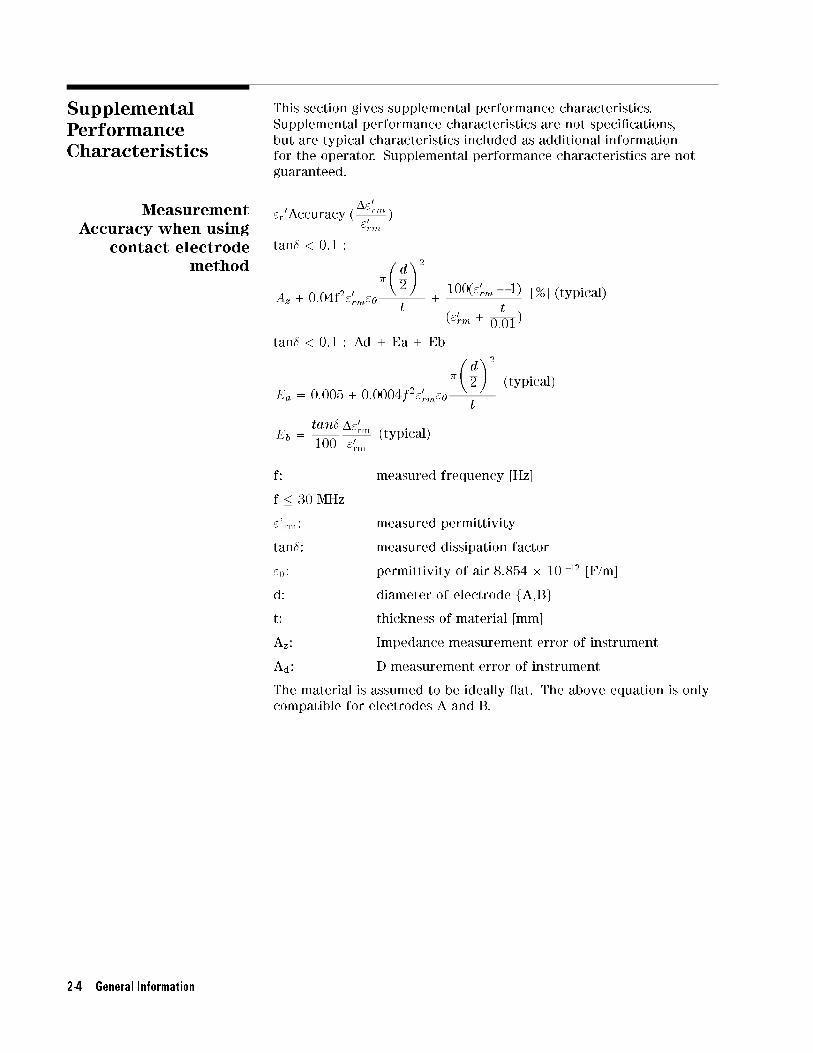
SupplementalPerformanceCharacteristics
This section gives supplemental performance characteristics.
Supplemental performance characteristics are not speci�cations,
but are typical characteristics included as additional information
for the operator. Supplemental performance characteristics are not
guaranteed.
Measurement
Accuracy when using
contact electrode
method
"r0Accuracy (
�"0rm
"0
rm
)
tan� < 0.1 :
Az +0:04f2"0rm"0
�
�d
2
�2
t+
100("0rm� 1)
("0rm
+t
0:01)
[%] (typical)
tan� < 0.1 : Ad + Ea + Eb
Ea = 0:005+ 0:0004f2"0rm"0
�
�d
2
�2
t
(typical)
Eb =tan�
100
�"0rm"0
rm
(typical)
f: measured frequency [Hz]
f � 30 MHz
"'rm: measured permittivity
tan�: measured dissipation factor
"0: permittivity of air 8.854 � 10 -12 [F/m]
d: diameter of electrode fA,Bg
t: thickness of material [mm]
Az: Impedance measurement error of instrument
Ad: D measurement error of instrument
The material is assumed to be ideally at. The above equation is only
compatible for electrodes A and B.
2-4 General Information
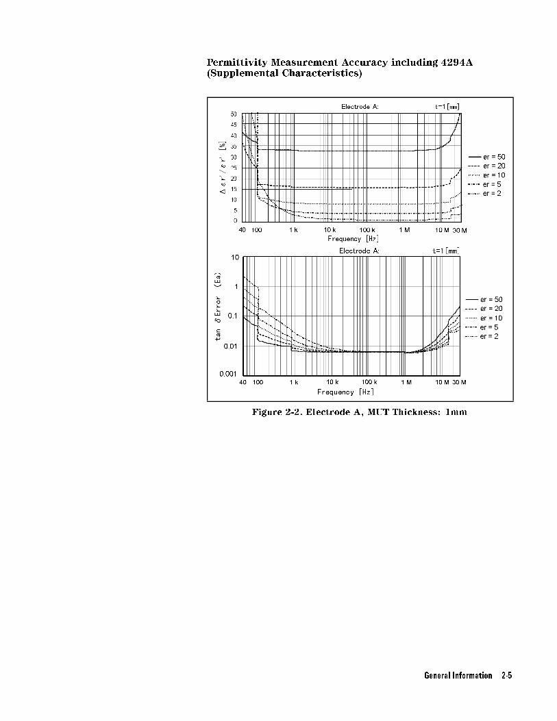
Permittivity Measurement Accuracy including 4294A(Supplemental Characteristics)
Figure 2-2. Electrode A, MUT Thickness: 1mm
General Information 2-5

Figure 2-3. Electrode B, MUT Thickness: 1mm
1. OSC LEVEL: 500 mV
2. BW: 5
3. ADAPTER TYPE: 4TP 1M
4. COMPENSATION: OPEN,SHORT & LOAD
2-6 General Information

Electrode DimensionsGuarded/Guard Electrode (4 types, changeable)
1. For materials without applied thin �lm electrodes
Figure 2-4. Dimensions of Electrode-A
Figure 2-5. Dimensions of Electrode-B
General Information 2-7

2. For materials with applied thin �lm electrodes
Figure 2-6. Dimensions of Electrode-C
Figure 2-7. Dimensions of Electrode-D
2-8 General Information
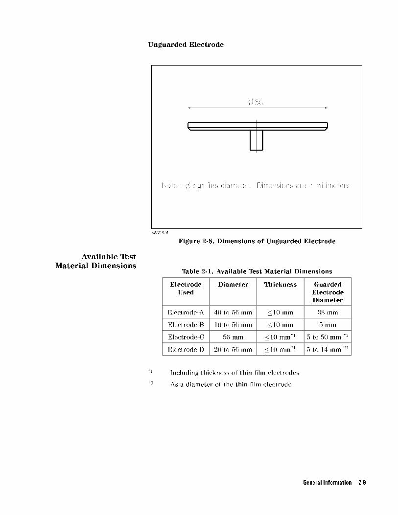
Unguarded Electrode
Figure 2-8. Dimensions of Unguarded Electrode
Available Test
Material DimensionsTable 2-1. Available Test Material Dimensions
ElectrodeUsed
Diameter Thickness GuardedElectrodeDiameter
Electrode-A 40 to 56 mm �10 mm 38 mm
Electrode-B 10 to 56 mm �10 mm 5 mm
Electrode-C 56 mm �10 mm*1 5 to 50 mm *2
Electrode-D 20 to 56 mm �10 mm*1 5 to 14 mm *2
*1 Including thickness of thin �lm electrodes
*2 As a diameter of the thin �lm electrode
General Information 2-9

Micrometer
Resolution
10 �m
Dimensions of Fixture
Assembly
Figure 2-9. Dimensions of Test Fixture Assembly
2-10 General Information

Storage andRepacking
This section describes the environment for storing or shipping the
16451B, and how to repackage the 16451B for shipment when
necessary.
Environmental
Requirements
The 16451B should be stored in a clean, dry environment. The
following environmental limitations apply for both storage and
shipment.
Temperature: -40�C to 70�C
Humidity: �95% RH (at 40�C)
To prevent condensation from taking place on the inside of the
16451B, protect the �xture against temperature extremes.
Original Packaging Containers and packing materials identical to those used in
factory packaging are available through your closest Agilent
Technologies sales o�ce. If the instrument is being returned to
Agilent Technologies for servicing, attach a tag indicating the
service required, the return address, the model number, and the full
serial number. Mark the container FRAGILE to help ensure careful
handling. In any correspondence, refer to the �xture by model
number and its full serial number.
Other Packaging The following general instructions should be used when repacking
with commercially available materials:
1. Wrap the 16451B in heavy paper or plastic. When shipping to a
Agilent Technologies sales o�ce or service center, attach a tag
indicating the service required, return address, model number, and
the full serial number.
2. Use a strong shipping container. A double-walled carton made of at
least 350 pound test material is the minimum adequate.
3. Use enough shock absorbing material (3 to 4 inch layer) around
all sides of the 16451B to provide a �rm cushion and to prevent
movement inside the container. Use cardboard to protect the front
panel.
4. Securely seal the shipping container.
5. Mark the shipping container FRAGILE to help ensure careful
handling.
6. In any correspondence, refer to the 16451B by model number and
its full serial number.
General Information 2-11


3
Operation
Introduction This chapter describes the product overview, basic theory of
measuring dielectric constant using the 16451B, methods for
measuring dielectric constant step by step, details of measurement
procedure basic measurement procedure summarized and typical
measurement procedures with measurement results using the 4194A
and 4284A. The last part of this chapter describes measurement error
factors.
Warning DO NOT apply more than �42 Vpeak total test signal level anddc bias voltage to the unknown terminals. An electrical shockhazard will exist during operation when the DC bias voltage isgreater than 42 V DC.
16451B Overview The 16451B is a test �xture for measuring disc and �lm dielectric
materials when connected to Agilent's LCR meters or impedance
analyzers, and is usable up to 15 MHz. The 16451B provides the
�xture assembly, four interchangeable Guarded/Guard electrodes
and accessories. Figure 3-1 shows the 16451B �xture assembly and
Figure 3-2 shows the accessories furnished with the 16451B.
Fixture Assembly The 16451B �xture assembly is equipped with a 4-terminal pair
cable assembly, Guarded/Guard electrodes, and a micrometer to set
the distance between the electrodes. The cable assembly can be
connected directly to the 4-terminal pair measurement terminals of
the instrument, and the con�guration is changed to a 3-terminal at
the Guarded/Guard electrodes. Figure 3-1 and Table 3-1 show the
con�guration name of each part of the �xture assembly.
Operation 3-1

Figure 3-1. Fixture Assembly
The name and description of the �xture assembly shown in Figure 3-1
are listed in the following table (Table 3-1).
3-2 Operation

Table 3-1. Name of Fixture Assembly
No. Name of Part Description
(1) Unguarded electrode This electrode is connected to the Hc(High current) and
Hp(High potential) terminal of the instrument.
(2) Guarded/Guard
electrode
This electrode is combined by a Guarded electrode and a
Guard electrode. The guarded electrode is connected to the
Lc(Low current) and Lp(Low potential) terminals of the
instrument. The guard electrode is connected to the guard
terminal. This electrode is interchangeable and is movable
using the knobs on the micrometer.
(3) Guarded/Guard
electrode attachment
screw
This screw secures the Guarded/Guard electrode.
(4) Micrometer The micrometer is used to adjust the distance between
electrodes. Do not use this to measure thickness the of test
material.
(5) Adjustment knob
(large knob)
This knob should be used for coarse adjustment of electrode
distance. Do not use the large knob to bring the
Guarded/Guard electrode into contact with the Unguarded
electrode or test material.
(6) Ratchet knob
(small knob)
This knob is used to bring the Guarded/Guard electrode into
contact with the Unguarded electrode or material.
(7) Cable assembly This cable assembly connects the 16451B to 4-terminal pair
UNKNOWN terminals on the instrument's front panel.
(8) Unguarded electrode
adjustment screws
These screws are used to make the Unguarded electrode
parallel with the Guarded/Guard electrode.
(9) Guarded/Guard
electrode pressure
adjuster
When the 16451B is placed so that the surface of electrodes
is horizontal, this adjuster pushes the Guarded/Guard
electrode to adjust its pressure on the Unguarded electrode to
be the same as when the 16451B is placed so that the surface
of electrodes is perpendicular.
Caution DO NOT use the large knob to bring the Guarded/Guard electrode into
contact with the Unguarded electrode or test material, doing so will
damage the micrometer or the surface of the electrodes. You must
use the small knob when you bring the electrode into contact with
another electrode or test material. It has a built in clutch which will
slip at a speci�ed torque.
Operation 3-3

Furnished Accessories The 16451B provides some accessories, such as 4 types of changeable
electrodes and their covers, an attachment for error correction, Hex
key, and Carrying case. Figure 3-2 and Table 3-2 show the furnished
accessories.
Figure 3-2. Furnished Accessories
3-4 Operation

Table 3-2. Name of Furnished Accessories
No. Name of accessory Description
(1) Electrode-A (38 mm
Guarded/Guard
electrode)
This electrode is used to measure a material without thin �lm
electrode and consists of a Guarded electrode ( 1 -a) and a
Guard electrode ( 1 -b). The diameter of guarded electrode is
38 mm. The electrode is provided with a cover ( 1 -c) to
protect its surface.
(2) Electrode-B (5 mm
Guarded/Guard
electrode)
This electrode is used to measure a material without thin �lm
electrodes and consists of a Guarded electrode ( 2 -a) and a
Guard electrode ( 2 -b). The diameter of guarded electrode is
5 mm. The electrode is provided with a cover ( 2 -c) to
protect its surface.
(3) Electrode-C (Electrode
for large thin �lm
electrodes)
This electrode is used to measure test materials which already
have thin �lm electrodes applied and consists of a Guarded
electrode ( 3 -a) and a Guard electrode ( 3 -b). The electrode is
provided with a cover ( 3 -c) to protect its surface.
(4) Electrode-D
(Electrode for small
thin �lm electrodes)
This electrode is used to measure test materials which already
have thin �lm electrodes applied and consists of a Guarded
electrode ( 4 -a) and a Guard electrode ( 4 -b). The electrode is
provided with a cover ( 4 -c) to protect its surface.
(5) Attachment for error
correction
This is an attachment used for OPEN and SHORT corrections.
5 -a shows the attachment and 5 -b shows its cover.
(6) Hex key This is a hex key used to interchanging and adjust the
electrodes.
(7) Carrying case This is a carrying case used to store and carry the �xture
assembly and its accessories.
Operation 3-5

DielectricMeasurement Basic
This section contains information of the basic theory of dielectric
measurements and its measurement methods.
Basic theory This section describes the basic theory of dielectric constant
measurement. The dielectric constant, a fundamental parameter of
insulating or dielectric materials, is calculated from the capacitance
value when the material is used as the dielectric. A practical
measurement procedure is described in \Typical Measurement
Procedure by the Measurement Methods". For the dielectric constant
calculation, consider a solid material which is shaped into a disc as
shown in Figure 3-3.
Figure 3-3. Basic Model for Dielectric Measurement
The dielectric constant can be obtained using the following equation.
� = �o�r
=t
ACp
Where,
� Dielectric constant (permittivity) [F/m]
�o Space permittivity = 8.854�10-12 [F/m]
�r Relative dielectric constant (Relative permittivity) of test
material
Cp Equivalent parallel capacitance value [F]
t Thickness of test material [m]
3-6 Operation

A Area of electrode [m2]
Thus, the relative dielectric constant (generally called the dielectric
constant) of the test material, �r, can be obtained by measuring the
capacitance value and calculating using the following equation.
�r =t� Cp
A� �o
=t � Cp
� �
�d
2
�2
� �o
Where,
d Diameter of electrode [m]
The dielectric dissipation factor (= tan�; loss tangent) of test material,
Dr can be obtained directly by measuring the dissipation factor.
If the diameter of electrode is 38 mm, the denominator of the above
mentioned equation becomes simple:
� �
�d
2
�2
� �o � 1� 10�14
Then, the equation to obtain the dielectric constant is :
�r = t � Cp � 1� 1014
Operation 3-7
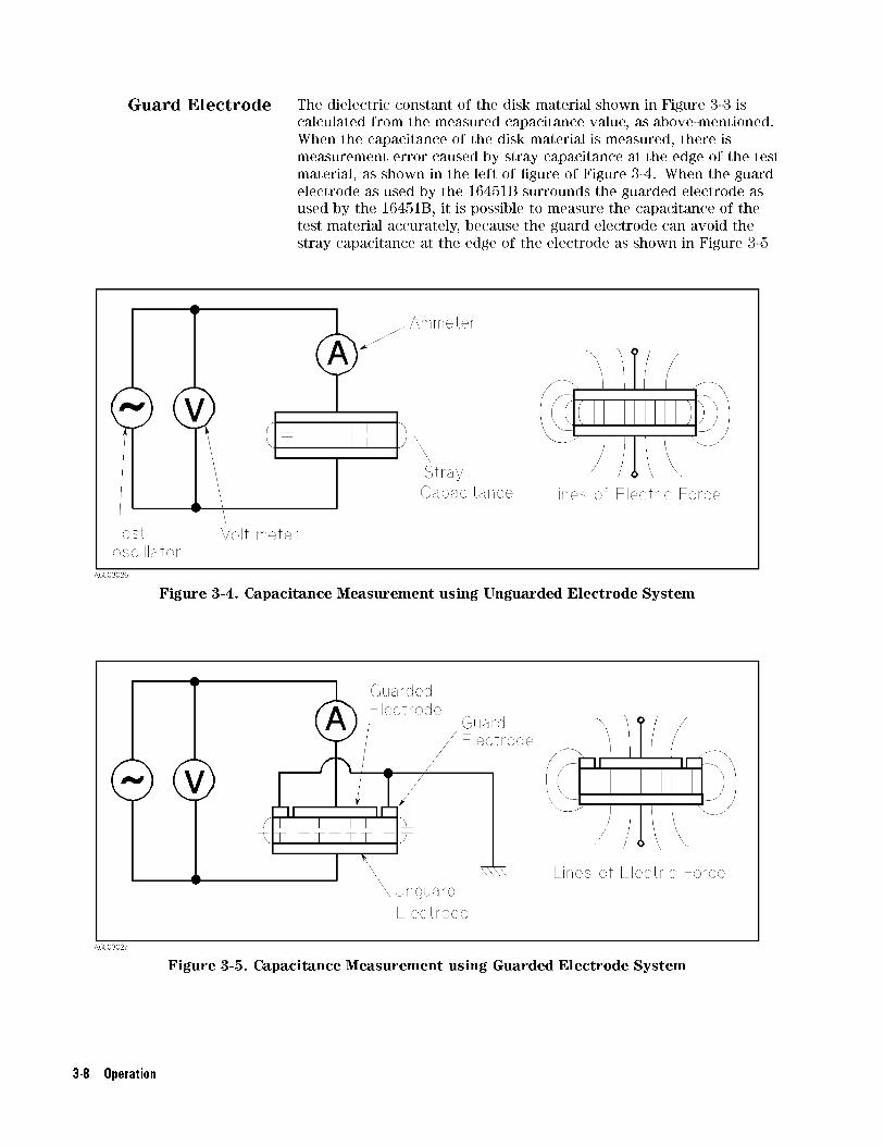
Guard Electrode The dielectric constant of the disk material shown in Figure 3-3 is
calculated from the measured capacitance value, as above-mentioned.
When the capacitance of the disk material is measured, there is
measurement error caused by stray capacitance at the edge of the test
material, as shown in the left of �gure of Figure 3-4. When the guard
electrode as used by the 16451B surrounds the guarded electrode as
used by the 16451B, it is possible to measure the capacitance of the
test material accurately, because the guard electrode can avoid the
stray capacitance at the edge of the electrode as shown in Figure 3-5
Figure 3-4. Capacitance Measurement using Unguarded Electrode System
Figure 3-5. Capacitance Measurement using Guarded Electrode System
3-8 Operation

MeasurementMethod
This section describes three applicable measurement methods for the
16451B.
As the previous section \Dielectric Measurement Basic" explains,
capacitance measurement of the test material is required when the
dielectric constant of a solid test material is to be obtained. There
are many kinds of methods to measure the capacitance of a solid
material. Three measurement methods are applicable to the 16451B,
they are the Contacting Electrode method (Rigid Metal electrode),
the Contacting Electrode method (Thin Film electrode) and the
Non-Contacting Electrode method (Air Gap method). You should select
the suitable measurement method and the suitable electrode for your
test material in order to measure it accurately.
Figure 3-6 shows a summary of three applicable measurement
methods and the sections that follow describe them in more detail.
Operation 3-9
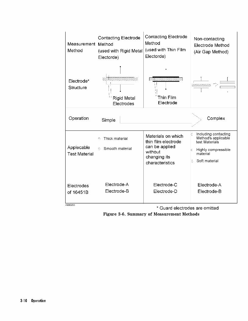
Figure 3-6. Summary of Measurement Methods
3-10 Operation

Contacting Electrode
Method (used with
Rigid Metal Electrode)
This method uses Rigid electrodes which make contact directly the
surface of the test material. This method is applicable for thick,
smooth or slightly compressible materials. The merits and demerits of
this method are as follows:
Merits
Procedure to measure capacitance is simple
It is not necessary to apply thin �lm electrodes
Equations to obtain dielectric constant are simple
Demerits
Air �lm (error caused by air gap between electrodes and surface
of the test material) causes error.
Principle
Figure 3-7 shows the schematic electrode structure for this method.
Figure 3-7. Contacting Electrode Method (Rigid Metal Electrode)
Operation 3-11

Dielectric constant and dissipation factor of a test material can be
obtained using the following equations.
Parameters Needed:
Cp Equivalent parallel capacitance [F]
D Dissipation factor
ta Average thickness of test material [m]
A Area of Guarded electrode [m2]
d Diameter of Guarded electrode [m]
(38�10-3 [m] or 5�10-3 [m])
�o =8.854�10-12 [F/m]
Equations:
�r =ta � Cp
A � �o
=ta � Cp
� �
�d
2
�2
� �o
Dt = D
Where,
�r Dielectric constant of test material
Dt Dissipation factor of test material
3-12 Operation

Electrodes of the 16451B
The 16451B provides two applicable electrodes, Electrode-A (38 mm
electrode) and Electrode-B (5 mm electrode), for the Contacting
Electrode method (Rigid Electrode method) to match the size of test
material as shown in Figure 3-8. When these electrodes are used,
the diameter of test materials should be much greater than the inner
diameter of the Guard electrode and smaller than or equal to 56 mm.
Figure 3-9 and Figure 3-10 show the applicable size of test material
for these electrodes.
Figure 3-8. Electrode of the 16451B for Contacting Electrode Method (Rigid Metal Electrode)
Operation 3-13

Applicable Size of Test Material for Electrode-A(38 mm Guarded/Guard Electrode)
Diameter of material greater than or equal to 40 mm and
smaller than or equal to 56 mm
Thickness of material less than or equal to 10 mm
Figure 3-9. Applicable Size of Test Material for Electrode-A
3-14 Operation

Applicable Size of Test Material for Electrode-B(5 mm Guarded/Guard Electrode)
Diameter of test material greater than or equal to 10 mm and
smaller than or equal to 56 mm
Thickness of test material less than or equal to 10 mm
Figure 3-10. Applicable Size of Test Material for Electrode-B
Operation 3-15

Contacting Electrode
Method (used with
Thin Film Electrode)
This method uses thin �lm electrodes applied on the test material.
The thin �lm electrodes contact with the 16451B's electrodes. This
method is applicable for materials on which the thin �lm electrodes
can be applied without changing its characteristics. It should be
noted that it is di�cult to remove the thin �lm electrodes after the
measurement. The merits and demerits of this method are as follows:
Merits
Air �lm (error caused by air gap between the electrode and
surface of the test material) causes minimum error
Procedure to measure capacitance is simple
Equations to obtain dielectric constant are simple
Demerits
It is necessary to apply the thin �lm electrodes (Not applicable to
materials which change their characteristics because of applying
the thin �lm electrodes.)
Principle
Figure 3-11 shows the schematic electrode structure for this method.
Figure 3-11. Contacting Electrode Method (Thin Film Electrode)
3-16 Operation

Dielectric constant and dissipation factor of a test material can be
obtained using the following equations.
Parameters Needed:
Cp Equivalent parallel capacitance [F]
D Dissipation factor
ta Average thickness of test material [m]
A Area of Guarded thin �lm electrode [m2]
d Diameter of Guarded thin �lm electrode [m]
�o =8.854�10-12 [F/m]
Equations:
�r =ta � Cp
A � �o
=ta � Cp
� �
�d
2
�2
� �o
Dt = D
Where,
�r Dielectric constant of test material
Dt Dissipation factor of test material
Thin Film Electrode
When this method is used, a metallic thin �lm is applied on surface of
the test material. For more details, refer to \Thin Film Electrode" in
\Preparation of Test Material".
Operation 3-17

Electrodes of the 16451B
The 16451B provides two applicable electrodes, Electrode-C(electrode
for large thin �lm electrodes) and Electrode-D (electrode for small
thin �lm electrodes), for the Contacting Electrode method (Thin
Film electrode) to match the size of the test material as shown in
Figure 3-12. When these electrodes are used, the diameter of the thin
�lm guarded electrode must be smaller than the inner diameter of
the guarded electrode of the 16451B and the diameter of the thin
�lm guard electrode must be greater than the inner diameter of the
guarded electrode of the 16451B. Figure 3-13 and Figure 3-14 show
the applicable size of test material for these electrode.
Figure 3-12. Electrode of the 16451B for Contacting Electrode Method (Thin Film Electrode)
3-18 Operation

Applicable Size of Test Material for Electrode-C(Guarded/Guard Electrode for Large Thin Film Electrode)
Diameter of test material 56 mm
Diameter of guarded
thin �lm electrode
greater than or equal to 5 mm and less
than or equal to 50 mm
Inner diameter of guard
thin �lm electrode
less than or equal to 52 mm and
greater than a diameter of guarded
thin �lm electrode.
Gap distance between
guarded thin �lm electrode
and guard thin �lm electrode
as small as practical (0.5 mm is
possible)
Thickness of material less than or equal to 10 mm
Figure 3-13. Applicable Size of Test Material for Electrode-C
Operation 3-19

Applicable Size of Test Material Electrode-D(Guarded/Guard Electrode for Small Thin Film Electrodes)
Diameter of test material greater than or equal to 20 mm and
less than equal to 56 mm
Diameter of guarded
thin �lm electrode
greater than or equal to 5 mm and less
than or equal to 14 mm
Inner diameter of guard
thin �lm electrode
less than and equal to 16 mm and
greater than a diameter of guarded
thin �lm electrode.
Gap distance between
guarded thin �lm electrode
and guard thin �lm electrode
as small as practical (0.5 mm is
possible)
Thickness of material less than or equal to 10 mm
Figure 3-14. Applicable Size of Test Material for Electrode-D
3-20 Operation

Non-contacting
Electrode Method
(Air Gap Method)
This method accurately derives the dielectric constant from the
capacitance di�erence between two measurements, without the test
material, the other with the test material. These two measurements
are made with the distance between the electrodes held constant.
This method is especially applicable for �lm materials, highly
compressible materials (such as foam rubber), or soft materials. The
merits and demerits of this method are as follows:
Merits
Air �lm (error caused by air gap between the electrode and the
surface of test material) does not cause error
It is not necessary to apply thin �lm electrodes
Demerits
It is necessary to measure capacitance twice
Equation to derive the dielectric constant is complex
Principle
Figure 3-15 shows the schematic electrode structure for this method.
Figure 3-15. Non-contacting method (Air Gap method)
Operation 3-21

Dielectric constant and dissipation factor of a test material can be
obtained with the following equations.
Parameters Needed:
Cs1 Series capacitance when the test material is not inserted [F]
D1 Dissipation factor when the test material is not inserted
tg Gap between Guarded/Guard electrode and Unguarded
electrode [m]
Cs2 Series capacitance when the test material is inserted [F]
D2 Dissipation factor when the test material is inserted
ta Average thickness of test material [m]
Equations:
�r =1
1�
�1�
Cs1
Cs2
��
tg
ta
Dt = D2 + �r � (D2 � D1)�
�tg
ta� 1
�
Where,
�r Dielectric constant of test material
Dt Dissipation factor of test material
3-22 Operation

Electrodes of the 16451B
The 16451B provides two applicable electrodes, Electrode-A (38 mm
electrode) and Electrode-B (5 mm electrode), for Non-contacting
Electrode method (Air Gap method) to match the size of test material
as shown Figure 3-16. When these electrodes are used, the diameter
of test materials must be much greater than the inner diameter of the
Guard electrode. Figure 3-17 and Figure 3-18 show the applicable size
of test materials for these electrodes.
Figure 3-16. Electrode of the 16451B for Non-Contacting Electrode Method (Air Gap Method)
Operation 3-23
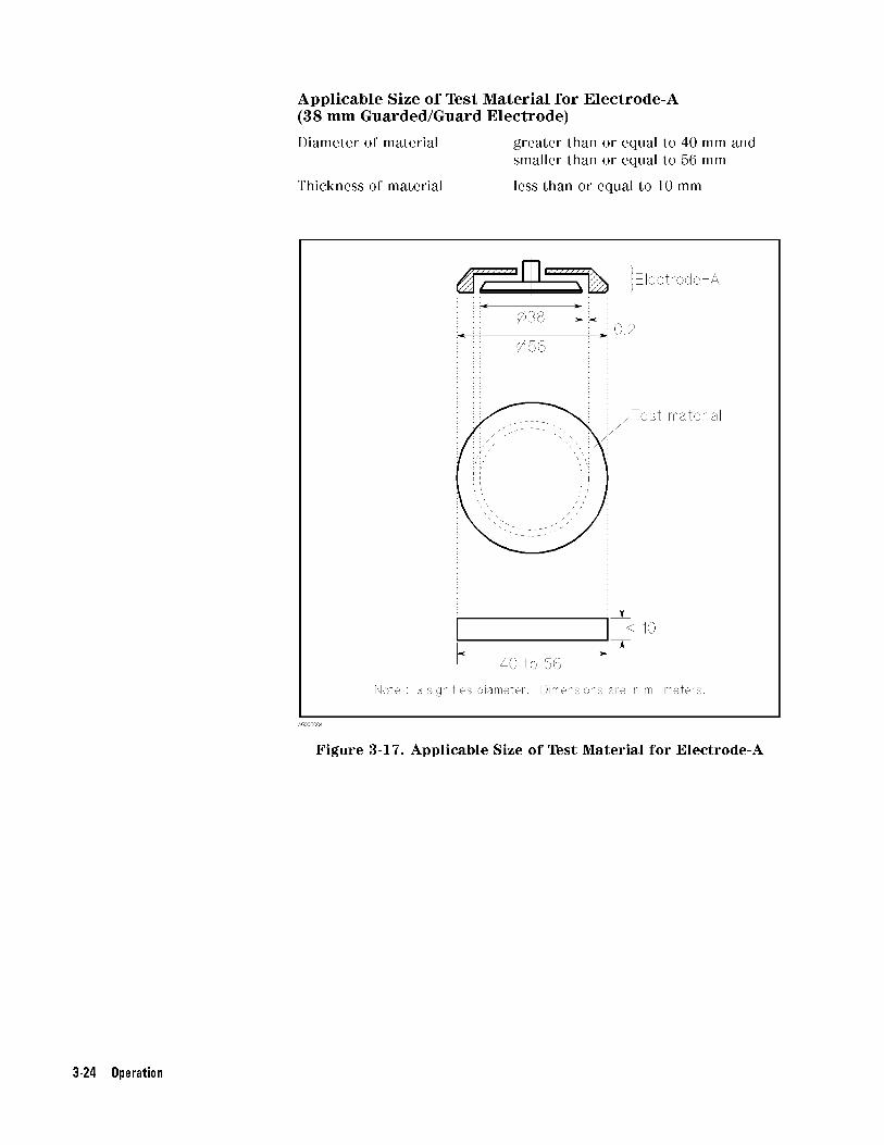
Applicable Size of Test Material for Electrode-A(38 mm Guarded/Guard Electrode)
Diameter of material greater than or equal to 40 mm and
smaller than or equal to 56 mm
Thickness of material less than or equal to 10 mm
Figure 3-17. Applicable Size of Test Material for Electrode-A
3-24 Operation

Applicable Size of Test Material for Electrode-B(5 mm Guarded/Guard Electrode)
Diameter of material greater than or equal to 10 mm and
smaller than or equal to 56 mm
Thickness of material less than or equal to 10 mm
Figure 3-18. Applicable Size of Test Material for Electrode-B
Operation 3-25

Preparation of TestMaterial
Dielectric constant measurement error is caused by not only
capacitance measurement error, but also by the error in the
test material dimensions. Therefore the test material should be
accurately cut or molded so that its dimensional error will not
a�ect the dielectric constant value. Before proceeding to the actual
measurement, read the following to prepare the test material.
Shape and Size of Test
Material
The applicable shape of the test material for the 16451B should be
a plate or a �lm. The applicable size (diameter) of the test material
should be greater than the inner diameter of the Guard electrode
used. The 16451B can also measure test materials whose shape is not
a disk, when the size of the test material is greater than the inner
diameter of the Guard electrode.
Caution Do not measure a material whose size (diameter) is much greater than
Unguarded electrode, doing so will overload electrodes and damage
them.
To obtain an accurate dielectric constant value, it is usually better to
use larger diameter and thinner thickness of the test material so that
its measured capacitance is greater. Therefore, when a low dielectric
constant material is measured, it is better to use larger electrode
(Electrode-A for using rigid metal electrodes and Electrode-C for using
thin �lm electrodes). If Electrode-B or Electrode-D is used when
low dielectric constant material is measured, you should change the
thickness of test material so that the capacitance value is large (more
than 0.1 pF). (For more detail, refer to next section \Thickness of Test
Material".)
Thickness of Test
Material
A thickness of a test material is limited to the 10 mm by the range for
moving the electrode of the 16451B. Because thickness is needed to
obtain the dielectric constant, you must know accurately thickness of
your test material. To reduce the reading error, you must average the
thickness values measured at the several points in the measurement
area and then use this averaged value to obtain the dielectric
constant.
Note Do not use the micrometer attached the 16451B to measure thickness
of test material, because it is for setting electrode distance and is not
good enough for an absolute measurement.
To obtain an accurate dielectric constant value, it is usually better to
use larger diameter and thinner thickness of the test material so that
its measured capacitance value is greater.
For example, when a test material whose dielectric constant is less
than 10 is measured using the 16451B with an LCR meter, the value
measured is only a few pF. When small capacitance is measured,
measurement error increases. To reduce the error and to obtain
accurate capacitance value, the capacitance value of your test
material must be in the range shown in Appendix B. So you should
change the thickness and diameter of your test material so that the
capacitance value of your test material is in that range.
3-26 Operation
When either Electrode-B or Electrode-D are used, the measured
capacitance value becomes too small because the diameter of the
electrode is small. Especially, when the dielectric constant of the test
material is less than 6, the capacitance value measured will be less
than 0.1 pF if the thickness of test material is too thick. Such a small
capacitance value is di�cult to measure accurately. Therefore, when
a test material whose dielectric constant is less than 6 is measured
using Electrode-B or Electrode-D, you must cut or mold your test
material so that the thickness (t) of the test material satis�es the
following conditions (capacitance value measured becomes greater
than 0.1 pF).
�o � �r �
� �
�d
2
�2
t� 0:1� 10�12
Where,
t Thickness of test material [m]
d Diameter of Guarded electrode [m]
�r Dielectric constant of test material
�o =8.854�10-12 [F/m]
Flatness of Test
Material's Surface
The surface of the test material must be at at all points. When the
Rigid Metal electrode (Electrode-A and Electrode-B) is used, atness
of the test material is especially important. If the surface of the test
material is not at, an air �lm (gap between an electrode and a test
material) increases and this causes measurement error. Measurement
error caused by non- atness will increase when the test material
is thin. For example, if the atness error is 10 �m, the dielectric
constant measurement error will be 0.3% for a material of 1 mm
thickness, but the error of capacitance measurement will be about
10% for a material of 40 �m thickness.
Thin Film Electrode Thin �lm electrodes can reduce the air gap between an electrode
and a test material. Therefore the air �lm error (error caused by
air gap between an electrode and a test material) using thin �lm
electrodes is less than one using rigid metal electrodes. There are
several types of thin �lms, such as Metal Foil, Conductive Paint,
Fired on Silver, Sprayed Metal, Evaporated Metal, and Metal
Spattering. Select the suitable thin �lm electrode. (For more detail,
refer to ASTM Standards:D150-81,\Standard Test Method for A-C
Loss Characteristics and Permittivity (Dielectric Constant) of Solid
Electrical Insulating Materials".) When attaching the thin �lm
electrode, the gap width between the guarded thin �lm electrode and
the guard thin �lm electrode should be as small as practical (0.5 mm is
possible).
Operation 3-27
Connecting to theInstrument
The 16451B can be connected directly to the measurement terminals
of a 4-terminal pair con�guration. Set the Cable Length switch or
softkey of the instrument to 1 m to compensate for the error caused
by the test leads of the 16451B. The procedure for setting the cable
length is di�erent by instrument, refer to the operation manual.
Changing theGuarded/GuardElectrode
This section describes the procedure to change the electrodes of the
16451B.
When you change an electrode, be careful not to contaminate or not
to make scratch on the surface of the electrode. Use lint free gloves
to prevent putting �ngerprints on it. Also, put the covers on both of
the electrodes before removing one. The removed electrode should be
stored in the carrying case. The electrode replacement procedure is as
follows.
1. Turn the small knob of the micrometer ccw (counterclockwise)
to move the Guarded/Guard electrode away from the Unguarded
electrode.
2. Put the covers on both electrodes to protect their surface.
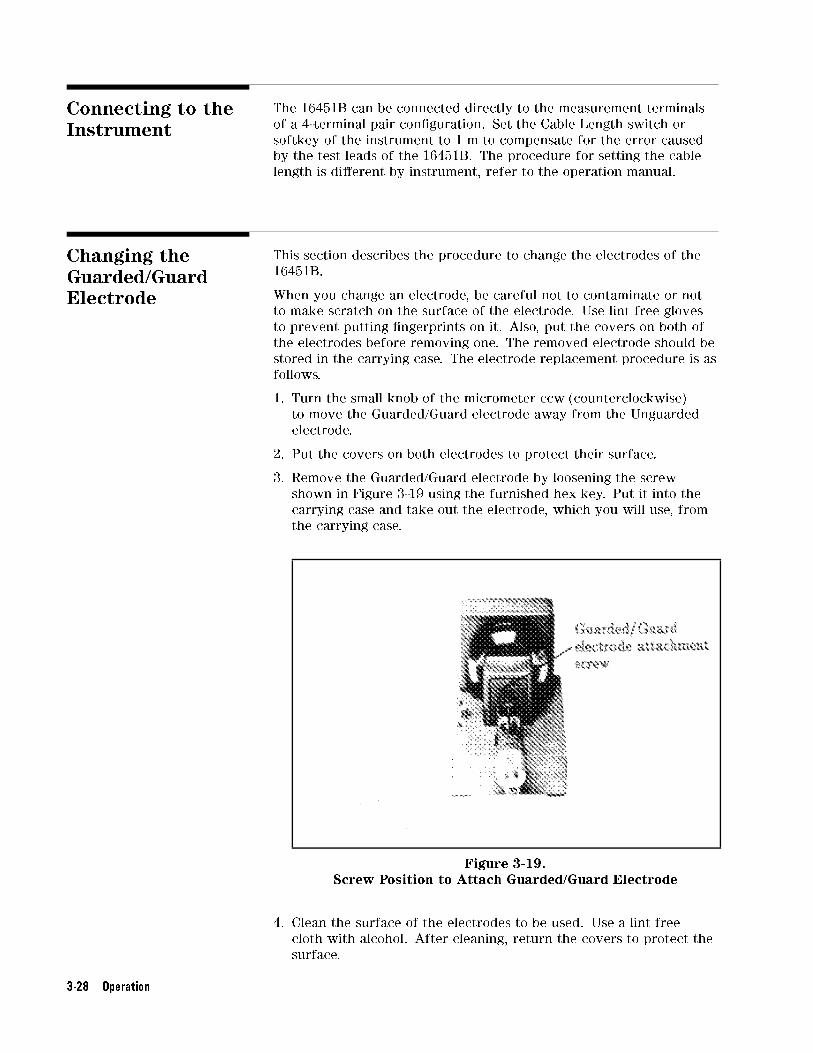
3. Remove the Guarded/Guard electrode by loosening the screw
shown in Figure 3-19 using the furnished hex key. Put it into the
carrying case and take out the electrode, which you will use, from
the carrying case.
Figure 3-19.Screw Position to Attach Guarded/Guard Electrode
4. Clean the surface of the electrodes to be used. Use a lint free
cloth with alcohol. After cleaning, return the covers to protect the
surface.
3-28 Operation

5. Connect the Guarded/Guard electrode and tighten the screw using
a hex key.
6. Turn the small knob until it slips when the covered electrodes
touch each other.
Note After the electrode is changed, you should adjust it for parallelism.
For the detailed adjustment procedure, refer to \Electrode
Adjustment".
Operation 3-29

Error Correction The recommended measurement instruments for the 16451B listed
in Table 1-2 have error correction functions to reduce residual
impedance and stray admittance in the 16451B. For precise dielectric
constant measurements perform the error correction. An error
correction attachment, furnished with the 16451B, is necessary.
Open Correction
(ZERO OPEN O�set
Adjustment)
The stray admittance contained in the 16451B can be reduced by
performing the following procedure.
1. Turn the small knob of the 16451B ccw to move the
Guarded/Guard electrode away from the Unguarded electrode.
2. After removing the covers of both electrodes, connect the
attachment with the cover to the Guarded/Guard electrode as
shown in Figure 3-20. As shown in Figure 3-21, the inner electrode
of the Guarded/Guard electrode is completely surrounded by the
guard.
Figure 3-20.Connecting the Attachment to the Guarded/Guard Electrode
for OPEN Correction
3. Turn the small knob of the 16451B cw (clockwise) to bring the
Unguarded electrode into contact with the attachment (until the
clutch slips). As shown in Figure 3-21, the inner electrode of the
Guarded/Guard electrode is completely surrounded by the guard.
3-30 Operation

Figure 3-21. OPEN Correction
4. Perform the OPEN correction measurement. (The procedure
to perform the OPEN correction depends on the measurement
instrument, for the details of this procedure, refer to Appendix C.)
5. Turn the small knob ccw to move the electrodes away from each
other, and remove the attachment.
Operation 3-31

Short Correction
(ZERO SHORT O�set
Adjustment)
The procedure to perform SHORT correction depends on the type
of the Guarded/Guard electrode used, so you should select the
appropriate procedure according to the Guarded/Guard electrode you
will use.
For Electrode-A and Electrode-B (Rigid Metal Electrode)
When you use Electrode-A (38 mm electrode) and Electrode-B (5 mm
electrode), the residual impedance contained in the 16451B can be
reduced by performing the following SHORT correction procedure.
1. Turn the small knob ccw to move the Guarded/Guard electrode
away from the Unguarded electrode.
2. After removing the cover from both electrodes, also remove the
cover from the attachment. Then connect the attachment to the
Unguarded electrode as shown in Figure 3-22.
Figure 3-22.Connecting the Attachment to the Unguarded Electrode for
SHORT Correction
3. Turn the small knob cw to bring the Guarded/Guard electrode into
contact with the attachment (until the clutch slips).
3-32 Operation

Figure 3-23. SHORT Correction for Rigid Metal Electrode
4. Perform the SHORT correction measurement. (The procedure
to perform the SHORT correction depends on the measurement
instrument, for the details of this procedure, refer to Appendix C.)
5. After the measurement, turn the small knob ccw to move the
electrodes away from each other and remove the attachment.
Operation 3-33
For Electrode-C and Electrode-D (Electrode for Thin FilmElectrodes)
When you use Electrode-C (electrode for large thin �lm electrodes)
and Electrode-D (electrode for small thin �lm electrodes), the residual
impedance contained in the 16451B can be reduced by performing the
following SHORT correction procedure
1. Turn the small knob ccw to move the Guarded/Guard electrode
away from the Unguarded electrode, then remove the cover from
both electrodes.
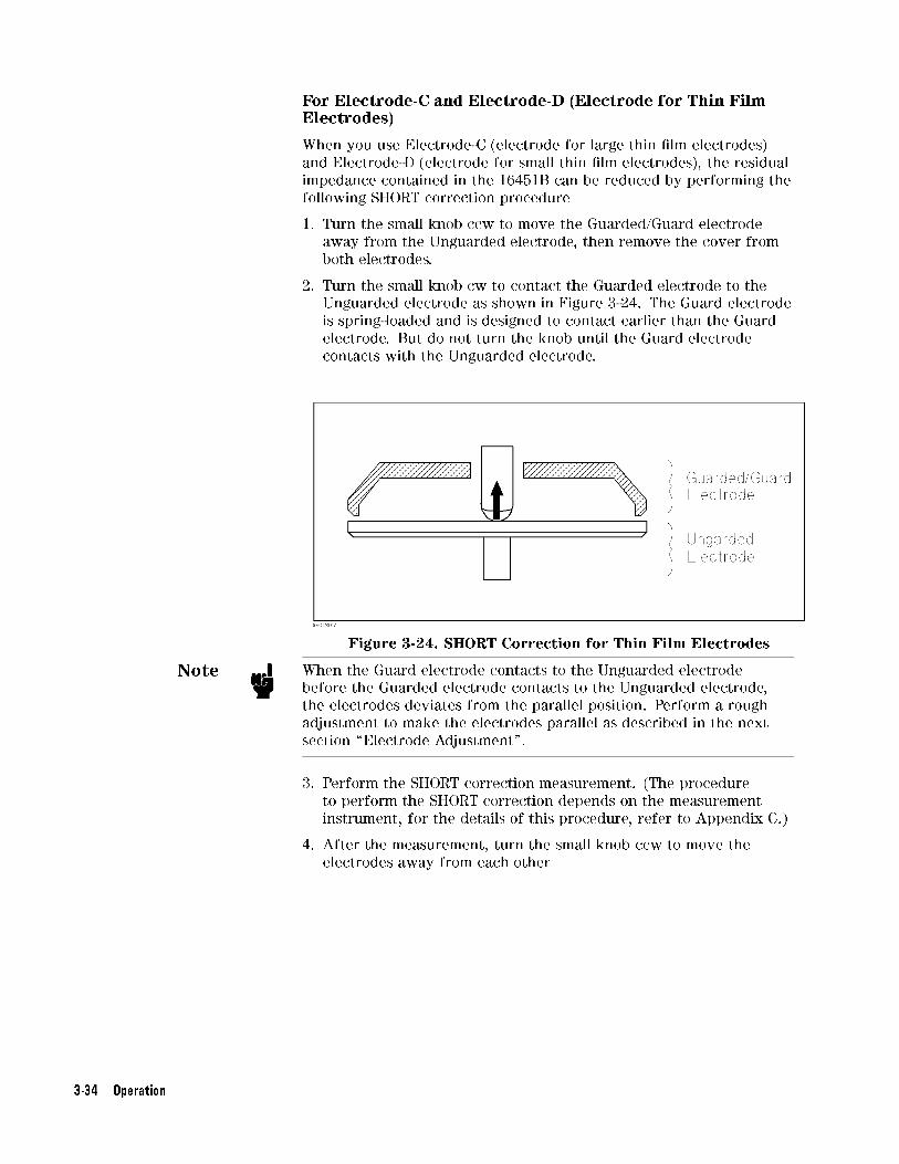
2. Turn the small knob cw to contact the Guarded electrode to the
Unguarded electrode as shown in Figure 3-24. The Guard electrode
is spring-loaded and is designed to contact earlier than the Guard
electrode. But do not turn the knob until the Guard electrode
contacts with the Unguarded electrode.
Figure 3-24. SHORT Correction for Thin Film Electrodes
Note When the Guard electrode contacts to the Unguarded electrode
before the Guarded electrode contacts to the Unguarded electrode,
the electrodes deviates from the parallel position. Perform a rough
adjustment to make the electrodes parallel as described in the next
section \Electrode Adjustment".
3. Perform the SHORT correction measurement. (The procedure
to perform the SHORT correction depends on the measurement
instrument, for the details of this procedure, refer to Appendix C.)
4. After the measurement, turn the small knob ccw to move the
electrodes away from each other
3-34 Operation

LOAD Correction
(LOAD Compensation)
If the measurement frequency exceeds 5 MHz, you must perform
LOAD compensation in addition to OPEN/SHORT compensation. Use
an air capacitor (adjust the distance between the electrodes to obtain
the value in the following table) as the standard when measuring
the LOAD compensation data. As the standard value for LOAD
compensation, use the equivalent parallel capacitance value (Cp)
measured at a low frequency (100 kHz). (It is assumed that the air
capacitor has no dependence on frequency.)
Electrodes Value of Load (Air Capacitor)
A 50 pF � 0.5 pF
B 5 pF � 0.05 pF
C and D 1.5 pF � 0.05 pF
Actual measurement procedure for the LOAD standard is as follows:
Adjust the distance between the 16451B's electrodes, measure Cp at
100 kHz, and sets it as the LOAD compensation standard value (Cp:
measured value and G: 0). Then, by maintaining the distance between
the electrodes, measure data as the LOAD compensation data at the
frequency points where you want to measure the material. For more
information, refer to the instrument's manual.
Operation 3-35

ElectrodeAdjustment
You should adjust the Guarded/Guard electrode until it is parallel
with the Unguarded electrode for accurate measurement. You must
perform this adjustment in the following cases:
Before measurement
After changing electrodes
When the result of the \Check Electrode Parallelism" fails (for more
details, refer to \Check Electrode Parallelism")
Note When you use Electrode-A or Electrode-B, and after you measure the
test material (or move the electrode) several times, it is recommended
to check for electrode parallelism (refer to \Check Electrode
Parallelism").
There are two adjustments, the one is a rough adjustment that
visually adjust the electrode and the other is an accurate adjustment
that electrically adjust the electrode using an LCR meter. (But the
second one is not necessary for Electrode-C and D). Depending on the
electrode you use, a di�erent adjustment procedure should be used as
follows.
Contacting electrode method (Rigid Metal method) : Using
Electrode-A, Electrode-B
1. Perform \Rough Adjustment to Make Electrodes Parallel"
2. Perform \Accurate Adjustment in Vertical Position"
Contacting electrode method (Thin Film electrode) : Using
Electrode-C, Electrode-D
1. Perform \Rough Adjustment to Make Electrodes Parallel"
Non-contacting electrode method (Air Gap method) : Using
Electrode-A, Electrode-B
1. Perform \Rough Adjustment to Make Electrodes Parallel"
2. Perform \Accurate Adjustment in Horizontal Position"
Caution DO NOT use the large knob to bring the Guarded/Guard electrode into
contact with the Unguarded electrode or the test material, doing so
may damage the micrometer or the surface of the electrodes. Use the
small knob when you bring the electrode into contact with another
electrode or test material. It has a built-in clutch which will slip at a
speci�ed torque.
Caution Do not turn the Unguarded electrode adjustment screws cw when the
Guarded/Guard electrode contacts Unguarded electrode. If you do so,
the micrometer will be overloaded and break.
Note You should perform the adjustment in the same environmental
conditions as you will measure the test material using the 16451B,
because a change of temperature causes mechanical dimensions to
change. When you change temperature condition, you should perform
the accurate adjustment after temperature conditions have changed,
3-36 Operation

because a change of temperature causes mechanical dimensions to
change.
Operation 3-37

Rough Adjustment to
Make Electrodes
Parallel
This adjustment is made by checking parallelism of the electrodes
visually. The adjustment requires the furnished hex key to adjust
the physical position of the Unguarded electrode. Use the following
procedure to perform this adjustment before the measurement and
after changing the electrodes.
1. Place the 16451B so that the surface of electrodes are vertical as
shown in Figure 3-25
Figure 3-25.Vertical Position and Electrode Adjustment Screws
2. Remove the covers on both electrodes and turn the small knob
of the micrometer cw to bring the Guarded/Guard electrode into
contact with the Unguarded electrode until the clutch slips.
3. Check if the micrometer's scale indicates less than zero. If the
clutch slips above zero, turn the small knob ccw to remove the
electrodes, and then turn three Unguarded electrode adjustment
screws (shown in Figure 3-25) ccw until the micrometer's scale
indicates below zero when Guarded/Guard electrode contacts
Unguarded electrode.
4. Check that there is no gap between the electrodes with the
electrodes contacting as shown in Figure 3-26.
5. If there is a gap, turn the furthermost adjustment screw from the
gap ccw to make the electrodes parallel and go to step 1. If you
can not see a gap, the rough adjustment is �nished.
3-38 Operation

Perform the next step \Accurate Adjustment to Make Electrodes
Parallel", when using the Contacting electrode method (Rigid metal
electrode) and Non-contacting Electrode method (Air Gap method).
Figure 3-26. Rough Adjustment Procedure
Operation 3-39
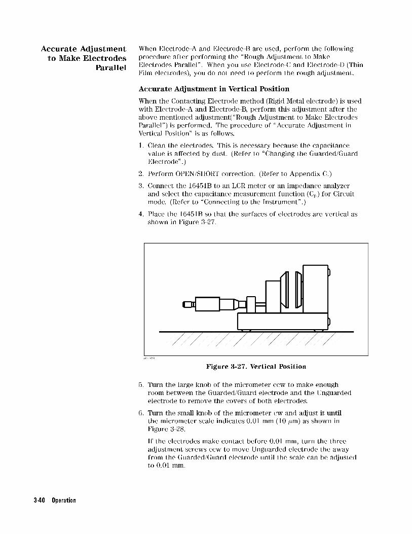
Accurate Adjustment
to Make Electrodes
Parallel
When Electrode-A and Electrode-B are used, perform the following
procedure after performing the \Rough Adjustment to Make
Electrodes Parallel". When you use Electrode-C and Electrode-D (Thin
Film electrodes), you do not need to perform the rough adjustment.
Accurate Adjustment in Vertical Position
When the Contacting Electrode method (Rigid Metal electrode) is used
with Electrode-A and Electrode-B, perform this adjustment after the
above mentioned adjustment(\Rough Adjustment to Make Electrodes
Parallel") is performed. The procedure of \Accurate Adjustment in
Vertical Position" is as follows.
1. Clean the electrodes. This is necessary because the capacitance
value is a�ected by dust. (Refer to \Changing the Guarded/Guard
Electrode".)
2. Perform OPEN/SHORT correction. (Refer to Appendix C.)
3. Connect the 16451B to an LCR meter or an impedance analyzer
and select the capacitance measurement function (Cp) for Circuit
mode. (Refer to \Connecting to the Instrument".)
4. Place the 16451B so that the surfaces of electrodes are vertical as
shown in Figure 3-27.
Figure 3-27. Vertical Position
5. Turn the large knob of the micrometer ccw to make enough
room between the Guarded/Guard electrode and the Unguarded
electrode to remove the covers of both electrodes.
6. Turn the small knob of the micrometer cw and adjust it until
the micrometer scale indicates 0.01 mm (10 �m) as shown in
Figure 3-28.
If the electrodes make contact before 0.01 mm, turn the three
adjustment screws ccw to move Unguarded electrode the away
from the Guarded/Guard electrode until the scale can be adjusted
to 0.01 mm.
3-40 Operation

Figure 3-28. The Micrometer Scale Adjusted to 0.01 mm
7. Measure the capacitance.
8. If the measured capacitance value is within the limits listed in
Table 3-3, adjustment is not necessary. If the capacitance value is
out of limits, go to the next step to make the electrodes parallel.
Table 3-3.Measured Capacitance Limits When the
Micrometer is Set to 0.01 mm
Electrode Capacitance Value
Electrode-A 700 pF to 1000 pF
Electrode-B 12 pF to 17 pF
9. Carefully turn the three adjustment screws cw or ccw until the
measured capacitance value is within the limits listed in Table 3-3.
Caution Stop turning the screw if the capacitance value becomes negative or
extremely high, or the dissipation factor (D) increases suddenly (the
electrodes are shorted). In this case, immediately turn the screws
ccw to separate the electrodes. If the screw is turned further, it may
damage the micrometer and the surface of electrodes.
Operation 3-41

Accurate Adjustment in Horizontal Position
When the Non-contacting Electrode method (Air Gap method) is used,
perform this adjustment after performing the \Rough Adjustment to
Make Electrodes Parallel". The procedure is as follows:
1. Clean the electrodes. This is necessary because the capacitance
value is a�ected by dust. (Refer to \Changing the Guarded/Guard
Electrode".)
2. Perform an OPEN/SHORT correction. (Refer to Appendix C.)
3. Connect the 16451B to an LCR meter or an impedance analyzer
and select the capacitance measurement function (Cp) for Circuit
mode. (Refer to \Connecting to the Instrument".)
4. Place the 16451B so that the surface of electrodes is vertical as
shown in Figure 3-27
5. Turn the large knob of the micrometer ccw to make enough
room between the Guarded/Guard electrode and the Unguarded
electrode, and then remove the cover from both electrodes.
6. Turn the small knob of the micrometer cw and adjust it until
the micrometer scale indicates 0.01 mm (10 �m) as shown in
Figure 3-28.
If the electrodes make contact before 0.01 mm, turn the three
adjustment screws ccw to move the Unguarded electrode away
from the Guarded/Guard electrode Unguarded electrode till the
scale can be adjusted to 0.01 mm.
Figure 3-29. Horizontal Position
3-42 Operation

7. Starting with the top adjustment screw, turn the three adjustment
screws cw in a clockwise sequence until the measured capacitance
value is within the limit listed as follows:
Table 3-4.Capacitance Point for Starting to Press the
Pressure Adjuster
Electrode Capacitance Value
Electrode-A Greater than 200 pF
Electrode-B Greater that 5 pF
Caution Stop turning the screw if the capacitance value becomes negative or
extremely high, or the dissipation factor (D) increases suddenly. In
this case, immediately turn the screw ccw to separate the electrodes.
If the screw is turned further, it may damage the micrometer and the
surface of electrodes.
When the measured capacitance value increases widely during
turning a screw, turn more slightly the screws.
8. Keep pressing the Guarded/Guard electrode pressure adjuster as
shown in Figure 3-25 and turn the three screws in a clockwise
sequence until the measured capacitance value is within the limits
listed in Table 3-5
Table 3-5. Capacitance Limits at Vertical Position
Electrode Capacitance Value
Electrode-A 700 pF to 1000 pF
Electrode-B 12 pF to 17 pF
Stop turning the screw if the capacitance value becomes
negative or extremely high, or the dissipation factor (D)
increases suddenly. In this case, immediately turn the screw ccw
to separate the electrodes and redo adjustment.
9. Place the 16451B so that the surface of electrodes are horizontal
and check that the measured capacitance value is within the limit
listed in Table 3-6
Table 3-6.Capacitance Limits at Horizontal Position
Electrode Capacitance Value
Electrode-A Greater than 700 pF
Electrode-B Greater than 12 pF
When the measured capacitance value is less than the limit,
place the 16451B so that the surface of electrodes are Vertical.
Then keep pressing Guarded/Guard pressure adjustment and
carefully turn the three screws in a clockwise sequence until the
measured capacitance value is within the limits in Table 3-6
Operation 3-43
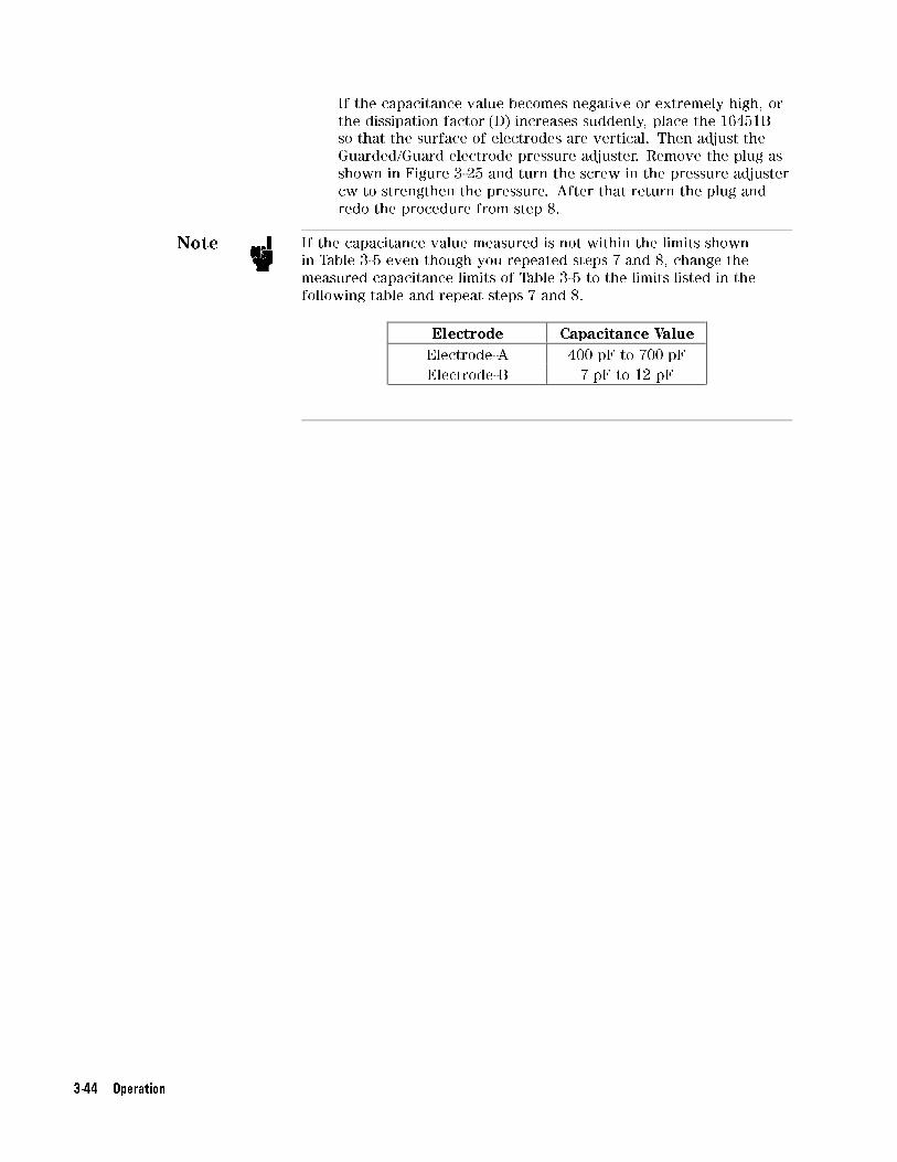
If the capacitance value becomes negative or extremely high, or
the dissipation factor (D) increases suddenly, place the 16451B
so that the surface of electrodes are vertical. Then adjust the
Guarded/Guard electrode pressure adjuster. Remove the plug as
shown in Figure 3-25 and turn the screw in the pressure adjuster
cw to strengthen the pressure. After that return the plug and
redo the procedure from step 8.
Note If the capacitance value measured is not within the limits shown
in Table 3-5 even though you repeated steps 7 and 8, change the
measured capacitance limits of Table 3-5 to the limits listed in the
following table and repeat steps 7 and 8.
Electrode Capacitance Value
Electrode-A 400 pF to 700 pF
Electrode-B 7 pF to 12 pF
3-44 Operation

TypicalMeasurementProcedure by theMeasurementMethods
The 16451B can be used for three measurement methods, Contacting
Electrode method (Rigid Metal electrode), Contacting Electrode
method (Thin Film electrode) and Non-Contacting Electrode method
(Air Gap method), to obtain the dielectric constant and dissipation
factor. This section provides typical measurement procedure for each
measurement method. (For information about how to select the
measurement method, refer to \Measurement Method".)
Caution DO NOT use the large knob to bring the Guarded/Guard electrode into
contact with the Unguarded electrode or test material, doing so will
damage the micrometer or the surface of the electrodes. You must use
the small knob when you bring an electrode into contact with another
electrode or test material. It has a built in clutch which will slip at a
speci�ed torque.
Note You should perform the adjustment in the same environmental
conditions as you will measure the test material using the 16451B,
because a change of temperature causes mechanical dimensions to
change. When you change temperature condition, you should perform
the accurate adjustment after temperature conditions have changed,
because a change of temperature causes mechanical dimensions to
change.
Contacting Electrode
Method
For the Contacting Electrode method, the 16451B provides two types
of electrodes, Rigid Metal electrodes (Electrode-A and Electrode-B)
and Electrode for Thin Film electrodes(Electrode-C and Electrode-D),
and provides two diameters for each type, so you should select the
electrodes. For more information on selecting electrode, refer to
\Contacting Electrode Method (used with Rigid Metal Electrode)"
and \Contacting Electrode Method (used with Thin Film Electrode)".
Figure 3-30 shows the model of Contacting Electrode (Rigid Metal
electrode) and Figure 3-31 shows the model of Contacting electrode
(Thin Film electrode).
Operation 3-45

Figure 3-30. Contacting Electrode Method (Rigid Metal Electrode)
Figure 3-31. Contacting Electrode Method (Thin Film Electrode)
Procedure
1. Prepare test material so that the 16451B can measure it.
(When you use Thin Film electrode, you should apply Thin Film
electrodes on the surface of the material to be measured. For more
information, refer to \Preparation of Test Material".)
2. Connect the 16451B to the instrument. (For more information,
refer to \Connecting to the Instrument".)
3. Set up the instrument to measure capacitance (Cp-D).
4. Change to the electrode you will use and perform the rough
adjustment. (Refer to \Changing the Guarded/Guard Electrode".)
3-46 Operation

5. Perform an OPEN/SHORT correction (Refer to \Error Correction".)
6. When you use the Electrode-A and Electrode-B, adjust the
electrodes to be parallel using the accurate adjustment. When you
use the Electrode-C and Electrode-D, you can skip this step. (Refer
to \Electrode Adjustment".)
7. Set the test material between the electrodes.
8. Measure the capacitance (Cp) and dissipation factor (D) and then
calculate the dielectric constant (�r) and dissipation factor (Dt) of
test material using the following equations.
Operation 3-47

Equations
�r =ta � Cp
A � �o
=ta � Cp
� �
�d
2
�2
� �o
Dt = D
Where,
Cp Equivalent parallel capacitance [F]
D Dissipation factor
ta Average thickness of test material [m]
A Area of Guarded electrode [m2]
d Diameter of Guarded electrode [m]
�o =8.854�10-12 [F/m]
�r Dielectric constant of test material
Dt Dissipation factor of test material
Note After you measure the test material (or move the electrode) several
times, it is recommended that you check electrode for parallelism
(refer to \Check Electrode Parallelism") and clean the surface of
electrodes.
Note For more information on measuring accurately, refer to \Measurement
Error Analysis".
3-48 Operation

Non-Contacting
Electrode Method
For the Non-Contacting method, the 16451B can perform an Air
Gap method. The 16451B provides two sizes of electrodes for the
Air Gap method, so you should select the electrode for the material
to be tested. For more information on selecting electrodes, refer to
\Measurement Method". Figure 3-32 shows a simple model of the
Non-Contacting method.
Figure 3-32. Non-Contacting Electrode Method (Air Gap Method)
Procedure
1. Prepare the test material so that the 16451B can measure it. (For
more information, refer to \Preparation of Test Material".)
2. Connect the 16451B to the instrument.(For more information,
refer to \Connecting to the Instrument".)
3. Set up the instrument to measure capacitance (Cs-D).
4. Change to the electrode you will use and perform the Rough
Adjustment. (Refer to \Changing the Guarded/Guard Electrode".)
5. Perform an OPEN/SHORT correction
6. Adjust the electrodes to be parallel using the Accurate
Adjustment. (Refer to \Electrode Adjustment".)
7. Set the test material between the electrodes.
8. Adjust the small knob of the micrometer to set the gap between
Guarded/Guard electrode and Unguarded electrode to tg so that
the gap distance between the Guarded/Guard electrode and the
test material is less than 10 % of thickness of the test material.
9. Measure capacitance (Cs2) and dissipation factor (D2)
10. Carefully remove the test material.
11. Measure capacitance (Cs1) and dissipation factor (D1) and then
calculate the dielectric constant (�) and dissipation factor (Dt)
using the following equations.
Operation 3-49

Equations
�r =1
1�
�1�
Cs1
Cs2
��
tg
ta
Dt = D2 + �r � (D2 � D1)�
�tg
ta� 1
�
Where,
Cs1 Capacitance without test material inserted [F]
D1 Dissipation factor without test material inserted
tg Gap between Guarded/Guard electrode and Unguarded
electrode [m]
Cs2 Capacitance with test material inserted [F]
D2 Dissipation factor with test material inserted
ta Average thickness of test material [m]
�r Dielectric constant of test material
Dt Dissipation factor of test material
Note After you measure the test material (or move the electrode) several
times, it is recommended to check for electrode parallelism (refer to
\Check Electrode Parallelism") and clean the surface of electrodes.
Note For more information on accurate measurement, refer to
\Measurement Error Analysis".
3-50 Operation

Check ElectrodeParallelism
This section describes the procedure to check that the electrodes are
parallel. When you measure test materials several times (or move the
electrode) using Electrode-A or Electrode-B, perform the following
procedure to check for electrode parallelism.
Remove the covers of both electrodes.
Turn the small knob of the micrometer cw and adjust it until the
micrometer scale indicates 0.01 mm (10�).
Measure the capacitance
If the measured capacitance value is within the limits listed in
Table 3-7, the check is �nished. If the capacitance value is out of
limits, perform the Accurate Adjustment as shown in \Accurate
Adjustment to Make Electrodes Parallel".
Table 3-7.Measured Capacitance Limits for Check Electrode
Parallelism
Electrode Capacitance Value
Electrode-A 700 pF to 1000 pF
Electrode-B 12 pF to 17 pF
Operation 3-51

MeasurementExamples
This section describes two practical examples of measuring dielectric
constant using the 16451B with the 4194A Impedance/Gain-phase
Analyzer, and with the 4284A Precision LCR meter.
Caution DO NOT use the large knob to bring the Guarded/Guard electrode into
contact with the Unguarded electrode or test material, doing so will
damage the micrometer or the surface of the electrodes. You must
use the small knob when you bring the electrode into contact with
another electrode or test material. It has a built in clutch which will
slip at a speci�ed torque.
Using the 4194A In this example, the Contacting Electrode method (Thin Film
electrode, Electrode-C or Electrode-D) is used. This sample procedure
performs OPEN/SHORT compensation, measures capacitance of test
material from 1 kHz to 10 MHz and derives the dielectric constant of
the test material.
1. Apply thin �lm electrodes to the surface of the material to be
measured.
2. Replace the electrodes (Electrode-C or Electrode-D) you will use
and adjust to make the electrodes parallel.
3. Set the CABLE LENGTH switch to the 1 m position.
4. Connect the 16451B to the 4194A's Impedance UNKNOWN
terminals and place the 16451B so that the surfaces of electrodes
are vertical.
5. Press �LINE� to turn the 4194A ON, if it is already ON, you must
turn it OFF once and then turn it ON again. Then press the blue
��� and press �R�, �S�, �T�, �ENTER/EXECUTE� to reset the 4194A.
6. Press �FUNCTION�,NNNNNNNNNNNNNNNNNNNNNNNNNNNNNIMPEDANCE ,
NNNNNNNNNNNNNNmore ,
NNNNNNNNNNNNNNCp-D (Parallel capacitance
and Dissipation factor) to select the Cp-D measurement function.
7. Press �SWEEP�,NNNNNNNNNNNNNNNNNNNNNNNNNNNNNLOG SWEEP to select the Log sweep mode.
8. Press �START�, �1�, �kHz�, �STOP�, �1�, �0�, �MHz� to set the START and
STOP frequencies for the sweep frequency range.
9. Put the attachment for error compensation with the cover on the
Guarded/Guard electrode then turn the small knob cw to bring it
into contact with the Unguarded electrode.
10. Press �COMPEN�,NNNNNNNNNNNNNNNNNNNNNNNNNNNNNZERO OPEN , �ENTER/EXECUTE� to perform an OPEN
compensation.
11. After Calibration completed is indicated and you hear the
beeping, remove the attachment.
12. Remove the cover on the attachment for error compensation and
put the attachment on the Unguarded electrode and bring the
Guarded/Guard electrode into contact with it.
13. Press �COMPEN�,NNNNNNNNNNNNNNNNNNNNNNNNNNNNNNNNZERO SHORT , �ENTER/EXECUTE� to perform a
SHORT compensation.
3-52 Operation
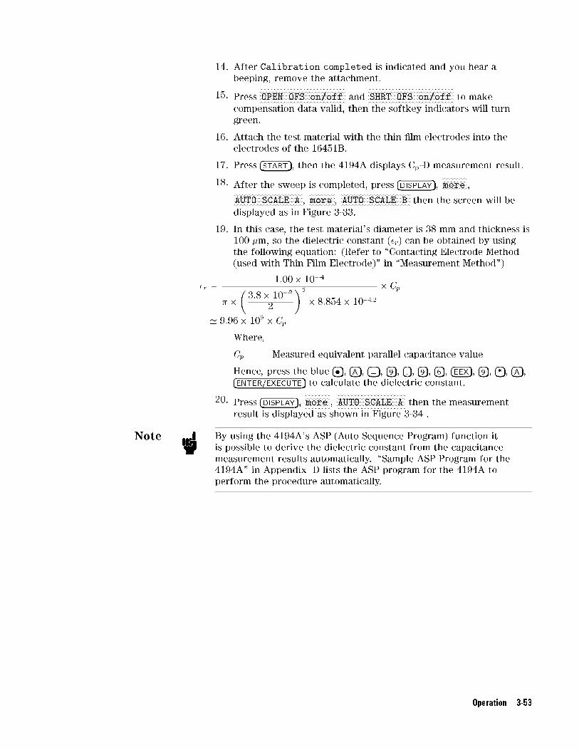
14. After Calibration completed is indicated and you hear a
beeping, remove the attachment.
15. PressNNNNNNNNNNNNNNNNNNNNNNNNNNNNNNNNNNNNNNNNNNNNNNNOPEN OFS on/off and
NNNNNNNNNNNNNNNNNNNNNNNNNNNNNNNNNNNNNNNNNNNNNNNSHRT OFS on/off to make
compensation data valid, then the softkey indicators will turn
green.
16. Attach the test material with the thin �lm electrodes into the
electrodes of the 16451B.
17. Press �START�, then the 4194A displays Cp-D measurement result.
18. After the sweep is completed, press �DISPLAY�,NNNNNNNNNNNNNNmore ,
NNNNNNNNNNNNNNNNNNNNNNNNNNNNNNNNNNNNNNAUTO SCALE A ,
NNNNNNNNNNNNNNmore ,
NNNNNNNNNNNNNNNNNNNNNNNNNNNNNNNNNNNNNNAUTO SCALE B then the screen will be
displayed as in Figure 3-33.
19. In this case, the test material's diameter is 38 mm and thickness is
100 �m, so the dielectric constant (�r) can be obtained by using
the following equation: (Refer to \Contacting Electrode Method
(used with Thin Film Electrode)" in \Measurement Method")
�r =1:00� 10�4
� �
�3:8� 10�2
2
�2
� 8:854� 10�12
� Cp
' 9:96� 109 � Cp
Where,
Cp Measured equivalent parallel capacitance value
Hence, press the blue ���, �A�, �=�, �9�, �.�, �9�, �6�, �EEX�, �9�, �*�, �A�,�ENTER/EXECUTE� to calculate the dielectric constant.
20. Press �DISPLAY�,NNNNNNNNNNNNNNmore ,
NNNNNNNNNNNNNNNNNNNNNNNNNNNNNNNNNNNNNNAUTO SCALE A then the measurement
result is displayed as shown in Figure 3-34 .
Note By using the 4194A's ASP (Auto Sequence Program) function it
is possible to derive the dielectric constant from the capacitance
measurement results automatically. \Sample ASP Program for the
4194A" in Appendix D lists the ASP program for the 4194A to
perform the procedure automatically.
Operation 3-53

Figure 3-33.Sample Result of Cp-D Measurement Using the 4194A
Figure 3-34.Sample Result of Dielectric Constant Using the 4194A
3-54 Operation

Using the 4284A In this example, the Non-Contacting method (Air Gap method) and
Electrode-A or Electrode-B is used. The sample procedure performs
OPEN/SHORT compensation and measures the capacitance of the test
material at 1 MHz.
1. Replace the electrodes (Electrode-A or Electrode-B) you will use
and adjust the electrodes for parallelism.
2. Press �MEAS SETUP�, andNNNNNNNNNNNNNNNNNNNNNNNNNNNNNNNNCORRECTION and move the cursor to the
CABLE: �eld and pressNNNNNNNNNNN1 m .
3. Connect the 16451B to the 4284A's Unknown Terminals and place
the 16451B so that the surface of electrodes is horizontal.
4. Press �DISPLAY FORMAT� and if the FUNC: �eld does not indicate
Cs-D move the cursor to the FUNC: �eld and pressNNNNNNNNNNNNNNCs-D .
5. Move the cursor to the FREQ: �eld and press �1�,NNNNNNNNNNNMHz to specify
the measurement frequency.
6. Put the attachment for error compensation with the cover on the
Guarded/Guard electrode then turn the small knob cw to bring
the attachment into contact with the Unguarded electrode.
7. Press �MEAS SETUP�, andNNNNNNNNNNNNNNNNNNNNNNNNNNNNNNNNCORRECTION . Move the cursor to the
OPEN: �eld and pressNNNNNNNNNNNNNNNNNNNNNNNNNNNNNMEAS OPEN to perform an OPEN correction
measurement.
8. After indicating Open measurement completed and beeping, pressNNNNNNNNON to validate the OPEN correction.
9. Turn the small knob ccw to remove the attachment.
10. Put the attachment for error compensation without the cover on
the Unguarded electrode then turn the small knob cw to bring the
Guarded/Guard electrode into contact with the attachment.
11. Move the cursor to the SHORT: �eld and pressNNNNNNNNNNNNNNNNNNNNNNNNNNNNNNNNMEAS SHORT to
perform SHORT correction measurement.
12. After indicating \Short measurement completed" and beeping,
pressNNNNNNNNON to validate the SHORT correction and remove the
attachment.
13. Press �DISPLAY FORMAT� to start the measurement.
14. Using the small knob of the 16451B, set the micrometer's scale
to 10 �m and adjust to set the electrodes accurately parallel.
(For more information of this procedure, refer to \Accurate
Adjustment to Make Electrodes Parallel")
15. After adjusting, put the test material into the gap between the
electrodes.
16. Set the micrometer's scale to (tg) so that the gap distance between
the Guarded/Guard electrode and the test material is below 10 %
of thickness of the test material..
17. Press �DISPLAY FORMAT� then the 4284A starts the measurement
and indicates the measurement capacitance value.
Operation 3-55
18. Record this measurement value as Cs2.
19. Remove the test material carefully and measure the capacitance
of the air gap.
20. Record this measurement value as Cs1.
21. You can obtain the dielectric constant (�r) using the following
equation: (Refer to \Non-contacting Electrode Method
(Air Gap Method)" in \Measurement Method")
�r =1
1�
�1�
Cs1
Cs2
��tg
ta
For example, Cs1= 4.055 pF, Cs2= 6.780 pF, ta=2.01 mm and tg=
2.20 mm then the calculated dielectric constant �r is 2.00.
Note The \Sample Program for the 4284A" in Appendix D lists a sample
BASIC program that runs on the 9000 series 300 Engineering
Workstation. The sample program controls the 4284A via GPIB and
automatically performs the following operation procedure. For more
information on the 4284A, such as GPIB commands, refer to the
4284A Operation Manual.
3-56 Operation

MeasurementError Analysis
This section describes error factors involved in dielectric constant
measurement using the Contacting Electrode method and
Non-contacting Electrode method, and how to perform measurements
with minimum error.
Note All data shown in this section, such as measurement accuracy,
and tolerance of electrode diameter, are typical values and are not
guaranteed.
Error Factor using
Contacting Electrode
Method
The dielectric constant of a test material is derived from measured
capacitance value. When using the Contacting Electrode method, the
dielectric constant �r of a test material is obtained using the following
equation.
�r =ta � Cp
� �
�d
2
�2
� �o
Where,
Cp Equivalent parallel capacitance [F]
ta Average thickness of test material [m]
d Diameter of Guarded electrode [m]
�o =8.854�10-12 [F/m]
The error factors included in the above parameters are as follow:
Capacitance measurement Error
This error is determined by the measurement accuracy of the LCR
meter or impedance analyzer used. Measurement accuracy of LCR
meters and impedance analyzers depends on the measurement
frequency and the measured impedance value. Generally, an LCR
meter and an impedance analyzer can accurately measure capacitance
above 1 pF. (For measurement frequency range of them, refer to
Table 1-2.) For more information on measurement accuracy of LCR
meters and impedance analyzers, refer to their Operation Manual or
Technical Data Sheet.
Operation 3-57

Tolerance of Guarded Electrode Diameter
This error depends on the electrodes mechanical accuracy. The typical
error for Electrode-A (�38 mm electrode) and Electrode-B (�5 mm
electrode) are given in Table 3-8.
Table 3-8. Tolerance of Electrode Diameter
Electrode Tolerance (typical)
Electrode-A (�38 mm Electrode) approximately �0.13%
Electrode-B (�5 mm Electrode) approximately �1.0%
Gap Error
This error consists of two factors as following:
Measurement Error of Test Material's Thickness (Error caused by
Micrometer) : Thickness measurement of the test material depends
on accuracy of the micrometer used. To reduce this error, measure
the thickness at several points of the measured area of the test
material using an accurate micrometer. Do not use the micrometer
equipped with the 16451B.
Parallelism and Flatness of Electrodes and Test Material : When
contacting the MUT directly with the electrodes, an airgap is formed
between the MUT and the electrodes. No matter how at and
parallel both sides of the MUT is fabricated, an airgap will still
form. This airgap is the cause for measurement error because the
measured capacitance will be the sum of the capacitance of the
dielectric material and the airgap. The relationship between the
airgap's thickness and measurement error is determined by the
equation shown in Figure 3-35. Measurement error is a function of
the relative permittivity (er') of the MUT, thickness of the MUT (d),
and the airgap's thickness (t). Sample results of measurement error
have been calculated in Table 3-9. Notice that the e�ect is greater
with thin materials and materials with high permittivity.
This airgap e�ect can be eliminated, by applying a thin �lm
electrode to the surfaces of the dielectric material. An extra step is
required for material preparation (fabricating a thin �lm electrode),
but the most accurate measurements can be performed.
3-58 Operation
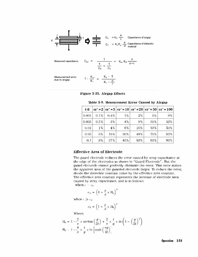
Figure 3-35. Airgap E�ects
Table 3-9. Measurement Error Caused by Airgap
t/d er'=2 er'=5 er'=10 er'=20 er'=50 er'=100
0.001 0.1% 0.4% 1% 2% 5% 9%
0.005 0.5% 2% 4% 9% 20% 33%
0.01 1% 4% 8% 16% 33% 50%
0.05 5% 16% 30% 48% 70% 83%
0.1 8% 27% 45% 63% 82% 90%
E�ective Area of Electrode
The guard electrode reduces the error caused by stray capacitance at
the edge of the electrodes as shown in \Guard Electrode". But the
guard electrode cannot perfectly eliminate the error. This error makes
the apparent area of the guarded electrode larger. To reduce the error,
divide the dielectric constant value by the e�ective area constant.
The e�ective area constant represents the increase of electrode area
caused by stray capacitance, and is as follows:
when � = �a
�a =
�1+
g
d
� Ba
�2when � � �a
�b =
�1+
g
d
� Bb
�2Where,
Ba = 1�2
�
� arctan
�g
2t
�+
2
�
�t
g� ln
�1+
�g
2t
�2�
Bb = 1�4
�
�t
g� ln
hcosh
��g
4t
�i
Operation 3-59

g Gap between Guard electrode and Guarded electrode [m]
(refer to Figure 3-8, Figure 3-12 and Figure 3-16)
d Diameter of Guarded electrode
t For Contacting Electrode method, thickness of the test
material (=ta) [m].
For Non-contacting Electrode method, gap between
Guarded/Guard electrode and Unguarded electrode (=tg) [m]
Table 3-10 lists the e�ective area constants �a , �b calculated for
Electrode-A (�38 mm electrode) and Electrode-B (�5 mm Electrode).
To reduce the error caused by stray capacitance at the edge, divide �a
or �b into equation to obtain dielectric constant as shown in following
equation
�r =ta � Cp
� �
�d
2
�2
� �o � �
3-60 Operation

Table 3-10. E�ective Area Constant
�a (�=�a) �b; (���a)
Electrode
distance [mm]
�38 mm �5 mm �38 mm �5 mm
10 1.0105 1.0526 1.0105 1.0524
9 1.0105 1.0526 1.0105 1.0524
8 1.0105 1.0525 1.0105 1.0523
7 1.0105 1.0525 1.0104 1.0523
6 1.0105 1.0525 1.0104 1.0522
5 1.0105 1.0525 1.0104 1.0521
4 1.0105 1.0524 1.0103 1.0520
3 1.0104 1.0523 1.0103 1.0518
2 1.0104 1.0521 1.0101 1.0513
1 1.0102 1.0516 1.0097 1.0500
0.9 1.0102 1.0515 1.0096 1.0497
0.8 1.0101 1.0513 1.0095 1.0493
0.7 1.0101 1.0511 1.0094 1.0488
0.6 1.0100 1.0508 1.0092 1.0482
0.5 1.0099 1.0505 1.0089 1.0473
0.4 1.0097 1.0499 1.0085 1.0460
0.3 1.0095 1.0490 1.0079 1.0438
0.2 1.0089 1.0473 1.0068 1.0397
0.1 1.0076 1.0423 1.0044 1.0293
0.09 1.0073 1.0413 1.0040 1.0274
0.08 1.0071 1.0401 1.0036 1.0253
0.07 1.0067 1.0387 1.0032 1.0230
0.06 1.0063 1.0387 1.0028 1.0203
0.05 1.0058 1.0346 1.0023 1.0173
0.04 1.0052 1.0317 1.0019 1.0140
0.03 1.0045 1.0278 1.0014 1.0106
0.02 1.0035 1.0225 1.0009 1.0071
0.01 1.0022 1.0147 1.0005 1.0035
(� means diameter.)
Operation 3-61
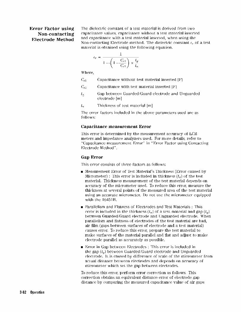
Error Factor using
Non-contacting
Electrode Method
The dielectric constant of a test material is derived from two
capacitance values, capacitance without a test material inserted
and capacitance with a test material inserted, when using the
Non-contacting Electrode method. The dielectric constant �r of a test
material is obtained using the following equation.
�r =1
1�
�1�
Cs1
Cs2
��tg
ta
Where,
Cs1 Capacitance without test material inserted [F]
Cs2 Capacitance with test material inserted [F]
tg Gap between Guarded/Guard electrode and Unguarded
electrode [m]
ta Thickness of test material [m]
The error factors included in the above parameters used are as
follows:
Capacitance measurement Error
This error is determined by the measurement accuracy of LCR
meters and impedance analyzers used. For more details, refer to
\Capacitance measurement Error" in \Error Factor using Contacting
Electrode Method".
Gap Error
This error consists of three factors as follows:
Measurement Error of Test Material's Thickness (Error caused by
Micrometer) : This error is included in thickness (ta) of the test
material. Thickness measurement of the test material depends on
accuracy of the micrometer used. To reduce this error, measure the
thickness at several points of the measured area of the test material
using an accurate micrometer. Do not use the micrometer equipped
with the 16451B.
Parallelism and Flatness of Electrodes and Test Materials : This
error is included in the thickness (ta) of a test material and gap (tg)
between Guarded/Guard electrode and Unguarded electrode. When
parallelism and atness of electrodes of the test material are bad,
air �lm (gaps between surfaces of electrode and a test material)
causes error. To reduce this error, prepare the test material to
make surfaces of the material parallel and at and adjust to make
electrode parallel as accurately as possible.
Error in Gap between Electrodes : This error is included in
the gap (tg) between Guarded/Guard electrode and Unguarded
electrode. It is caused by di�erence of scale of the micrometer from
actual distance between electrodes and depends on accuracy of
micrometer which set the gap between electrodes.
To reduce this error, perform error correction as follows. This
correction obtains an equivalent distance error of electrode gap
distance by comparing the measured capacitance value of air gaps
3-62 Operation

between electrodes and their theoretical value. Use the following
procedure:
1. Measure the capacitance at three di�erent electrode distances,
such as 40 �m, 50 �m, and 60 �m.
2. Calculate the theoretical capacitance value of each distance. The
theoretical capacitance value Ct can be obtained as follows.
Ct = �a � �0 �� � (d=2)2
tset
� �a
Where,
Ct Theoretical capacitance value [F]
�a Dielectric constant of air (=1.00059)
�0 = 8.854 � 10-12 [F/m]
�a E�ective area coe�cient of electrode when the electrode
distance is tset.
(Refer to \E�ective Area of Electrode" in \Error Factor
using Contacting Electrode Method".)
tset Reading value of the electrode distance on the micrometer
[m]
3. Calculate the equivalent distance error at each electrode distance.
The equivalent distance error of each electrode distance �te can be
obtained as follows:
�te =
�Ct
Cm
� 1
�� tset [m]
Where,
Cm Measured capacitance value [F]
4. Average equivalent distance error The average of equivalent
electrode distance error �ta is derived as follows.
�ta =�t40 +�t50 +�t60
3[�m]
Where,
�t40 Equivalent distance error �te at 40 �m
�t50 Equivalent distance error �te at 50 �m
�t60 Equivalent distance error �te at 60 �m
The equivalent electrode distance teq can be derived from a set
value of micrometer tset and equivalent distance error �ta shown as
follows:
teq = tset + �ta
The compensated dielectric constant is obtained as follows:
�r =1
1 �
�1�
Cs1
Cs2��b
�a
��teq
ta
Where, �a and �b are E�ective area constants. For more
information, refer to \E�ective Area of Electrode".
Operation 3-63
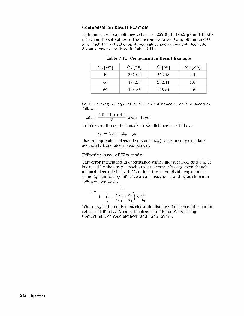
Compensation Result Example
If the measured capacitance values are 227.6 pF, 185.2 pF and 156.58
pF, when the set values of the micrometer are 40 �m, 50 �m, and 60
�m. Each theoretical capacitance values and equivalent electrode
distance errors are listed in Table 3-11.
Table 3-11. Compensation Result Example
tset [�m] Cm [pF] Ct [pF] �te [�m]
40 227.60 252.48 4.4
50 185.20 202.11 4.6
60 156.58 168.51 4.6
So, the average of equivalent electrode distance error is obtained as
follows:
�ta =4:6+ 4:6+ 4:4
3' 4:5 [�m]
In this case, the equivalent electrode distance is as follows:
teq = tset +4:5� [m]
Use the equivalent electrode distance (teq) to accurately calculate
accurately the dielectric constant �r.
E�ective Area of Electrode
This error is included in capacitance values measured Cs1 and Cs2. It
is caused by the stray capacitance at electrode's edge even though
a guard electrode is used. To reduce the error, divide capacitance
value Cs1 and Cs2 by e�ective area constants �a and �b as shown in
following equation.
�r =1
1 �
�1�
Cs1
Cs2��b
�a
��teq
ta
Where, teq is the equivalent electrode distance. For more information,
refer to \E�ective Area of Electrode" in \Error Factor using
Contacting Electrode Method" and \Gap Error".
3-64 Operation

4
Service
Introduction This chapter gives the service information for the 16451B. Service
information covers Assembly Replacement and Troubleshooting.
AssemblyReplacement
This section gives 16451B assembly and disassembly hints, and lists
the replaceable parts.
Assembly and
Disassembly Hints
The assemblies in the 16451B are secured using metric threaded
fasteners. All fasteners used in the 16451B, can be removed using
medium and small pozidrive screwdrivers and a 2.5 mm hex key. A
2.5 mm hex key (Agilent PN 8710-1181) is included with the 16451B.
Slide Stand Assembly
Do not remove any part of the Slide Stand Assembly (Agilent PN
16451-60002) shown in Figure 4-1. Once the Slide Stand Assembly
is disassembled, it cannot be reassembled, because special tools are
required for reassembly.
Figure 4-1. Slide Stand Assembly
Service 4-1

Micrometer Stand Replacement
When replacing the micrometer stand, press it against the slide stand
assembly's guide and align the back edge of the micrometer stand and
the slide stand assembly, as shown in Figure 4-2.
Figure 4-2. Micrometer Stand Replacement
Micrometer Replacement
When replacing the micrometer, put the micrometer completely into
the micrometer stand and turn the �ne scale adjustment line until it is
facing vertical, as shown in Figure 4-3. Then tighten the micrometer
stand's set screw to �rmly attach the micrometer to the stand. The
proper tightening torque is 3 kgf/cm. (About 3 kgf/cm may be applied
to the screw when the furnished hex key is used.) If the screw is
tighten too much, the micrometer will not function smoothly.
Figure 4-3. Micrometer Replacement
4-2 Service
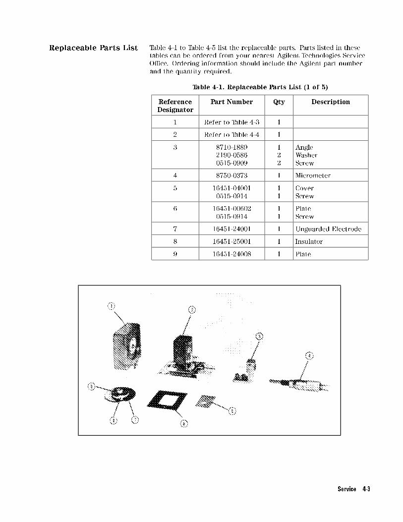
Replaceable Parts List Table 4-1 to Table 4-5 list the replaceable parts. Parts listed in these
tables can be ordered from your nearest Agilent Technologies Service
O�ce. Ordering information should include the Agilent part number
and the quantity required.
Table 4-1. Replaceable Parts List (1 of 5)
ReferenceDesignator
Part Number Qty Description
1 Refer to Table 4-3 1
2 Refer to Table 4-4 1
3 8710-1889
2190-0586
0515-0909
1
2
2
Angle
Washer
Screw
4 8750-0373 1 Micrometer
5 16451-04001
0515-0914
1
1
Cover
Screw
6 16451-00602
0515-0914
1
1
Plate
Screw
7 16451-24001 1 Unguarded Electrode
8 16451-25001 1 Insulator
9 16451-24008 1 Plate
Service 4-3

Table 4-2. Replaceable Parts List (2 of 5)
ReferenceDesignator
Part Number Qty Description
1 16541-04003
0403-0427
0515-0914
1
8
4
Cover Bottom
Bumper Foot
Screw
2 16451-04002 1 Cover Top
3 16451-61002 1 Cable Assembly
4* 16047-40000
2190-0206
0515-1550
1
1
1
Stopper
Washer
Screw
5* 16451-04004
0515-0914
1
2
Cover Top
Screw
*:These parts are included in the 16451-61002.
4-4 Service

Table 4-3. Replaceable Parts List (3 of 5)
ReferenceDesignator
Part Number Qty Description
1 16451-20002 1 Base
2-A 16451-25007 1 Spacer
2-B 16451-61602 1 Cable Assembly
2-C 1460-2237 1 Spring
2-D 16451-25004 1 Bushing
2-E 0515-1321 1 Screw
3 0515-1321
16451-25008
3
3
Screw*
Spacer
4-A 1460-2238 1 Spring
4-B 16451-25009 1 Rod
4-C 0515-1321 1 Screw
4-D 16451-25011 1 Rod
4-E 6960-0147 1 Plug Hole
5 0515-1550 1 Screw
*:Apply a drop of Lock-Tite (Agilent PN 0470-0013) to the screws,
when replacing them.
Service 4-5

Table 4-4. Replaceable Parts List (4 of 5)
ReferenceDesignator
Part Number Qty Description
1 16451-60002 1 Slide Stand Assembly
2-A 16451-25002 1 Spacer
2-B 16451-61602 1 Cable Assembly
2-C 2190-0584 1 Washer
2-D 0515-1321 1 Screw
2-E 16451-25006 1 Spacer
3 0515-1550 1 Screw
4-6 Service

Table 4-5. Replaceable Parts List (5 of 5)
Description Part Number
Electrode-A 16451-60011
Electrode-B 16451-60013
Electrode-C 16451-60012
Electrode-D 16451-60014
Error Compen. Attachment 16451-24011
Cover 56 mm 16451-25021
Cover 20 mm 16451-25022
Hex Key 8710-1181
Carrying Case 16451-60001
Electrodes A and C include a 56 mm Cover. Electrodes B and D
include a 20 mm Cover.
Electrode-A: 38 mm Guarded/Guard electrode
Electrode-B: 5 mm Guarded/Guard electrode
Electrode-C: Guarded/Guard electrode for large thin �lm electrode
Electrode-D: Guarded/Guard electrode for small thin �lm electrode
Service 4-7

Troubleshooting
Mechanical Trouble When the 16451B is mechanically defective, replace the defective
parts, refer to \Assembly Replacement", and con�rm that the
electrode distance can be changed smoothly from 0 to 10 mm. If the
electrode does not move smooth it may be because the cables are
obstructing the operation.
Electrical Trouble When the 16451B is electrically defective, check its cable connections,
refer to Figure 4-4. The connection check points are as follows:
The Lcur and Lpot Center conductors are connected to the Guarded
Electrode.
The Hcur and Hpot Center conductors are connected to the
Unguarded Electrode.
The Lcur, Lpot, Hcur, and Hpot outer conductors are connected
to the body. (The cables' shields are connected to the body with
screws.)
The Guard Electrode is connected to the body.
Insulation resistance between the Lpot center conductor and the
Hpot center conductor is greater than 1 M.
Insulation resistance between the center conductors and the outer
conductors is greater than 1 M
If the cable connections are correct, the electrodes may be defective.
Operation Check The Electrode Parallel Accurate Adjustment, described in \Electrode
Adjustment" in Chapter 3, can be used for the before and after repair
operation check. The adjustment cannot be completed when the
16451B is electrically defective.
4-8 Service

Figure 4-4. Cable Connection Diagram
Service 4-9

A
Manual Changes
Introduction This appendix contains the information required to adapt this manual
to earlier versions or con�gurations of the 16451B than the current
printing date of this manual. The information is this manual applies
directly to 16451B Dielectric Test Fixture whose serial number pre�x
is listed on the title page of this manual.
Manual Changes To adapt this manual to your 16451B , refer to Table A-1, and make all
of the manual changes listed opposite your �xture's serial number.
Fixtures manufactured after the printing of this manual may be
di�erent than those documented in this manual. Later �xture
versions will be documented in a manual changes supplement that
will accompany the manual shipped with that �xture. If your �xture
serial number is not listed on the title page of this manual or in
Table A-1, it may be documented in a yellow MANUAL CHANGES
supplement.
For additional information on serial number coverage, refer to \Serial
Number" in Chapter 2.
Table A-1. Manual Changes by Serial Number
Serial Pre�xor Number
Make Manual Changes
There are no earlier con�gurations than the
printing date of this manual.
Manual Changes A-1


B
Recommended Capacitance Range
This section shows the recommended capacitance range of test
materials for using the 16451B with Electrode-A (�38 mm electrode)
or Electrode-B (�5 mm electrode).
Using Electrode-A(�38 mm electrode)
The area surrounded by bold lines in Figure B-1 shows the
recommended capacitance range when using Electrode-A.
Figure B-1. Recommended Capacitance Range Using Electrode-A
Recommended Capacitance Range B-1

Using Electrode-C(�5 mm electrode)
The area surrounded by bold lines in Figure B-2 shows the
recommended capacitance range when using Electrode-B.
Figure B-2. Recommended Capacitance Range Using Electrode-B
B-2 Recommended Capacitance Range

C
Correction Procedure
4192A 1. Connect the attachment without the cover to the Unguarded
electrode of the 16451B.
2. Press �BLUE�, �SHORT�. The indicator lamp will come ON and
R(resistance) and X(reactance) o�set adjustments are automatically
performed at the spot frequency displayed on DISPLAY C.
CAL(calibration) is displayed on DISPLAY A and will remain ON
until the o�set adjustment is completed; a value of approximately
zero will then be displayed.
3. Remove the attachment from the electrode.
4. Connect the attachment with the cover to the Guarded/Guard
electrode.
5. Set the circuit mode to .
6. Press �BLUE�, �OPEN� then the indicator lamp will come ON and
G(conductance) and B(susceptance) o�set adjustments are
automatically performed at the spot measuring frequency displayed
on DISPLAY C. CAL(calibration) is displayed on DISPLAY A and
will remain ON until the o�set adjustment is completed; a value of
approximately zero will then be displayed.
7. Remove the attachment from the electrodes and store it with the
cover in the carrying case.
Correction Procedure C-1

4194A 1. Connect the attachment with the cover to the Guarded/Guard
electrode.
2. Press �COMPEN�,NNNNNNNNNNNNNNNNNNNNNNNNNNNNNZERO OPEN , �ENTER/EXECUTE� to start the OPEN
o�set measurement to collect data to be used for correction.
The Measuring zero open message will be displayed for several
seconds, then the Zero open compen complete message will
appear. The measurement data will not be displayed.
3. Remove the attachment from the electrode.
4. Connect the attachment without the cover to the Unguarded
electrode of the 16451B.
5. Press �COMPEN�,NNNNNNNNNNNNNNNNNNNNNNNNNNNNNNNNZERO SHORT , �ENTER/EXECUTE� to start the SHORT
o�set measurement for correction. The message Measuring zero
short will be displayed for several seconds, then Zero short
compen complete will be displayed. Measurement data will not be
displayed.
6. PressNNNNNNNNNNNNNNNNNNNNNNNNNNNNNNNNNNNNNNNNNNNNNNNOPEN OFS on/off ,
NNNNNNNNNNNNNNNNNNNNNNNNNNNNNNNNNNNNNNNNNNNNNNNSHRT OFS on/off to compensate
measurements using previously acquired OPEN/SHORT-o�set data.
7. Remove the attachment from the electrode and store it with the
cover in the carrying case.
C-2 Correction Procedure

4274A and 4275A
Caution Before proceeding with zero o�set adjustment, verify that bias
indicator lamp is not ON. If illuminated, set rear panel DC bias switch
to OFF.
1. Connect the attachment with the cover to the Guarded/Guard
electrode.
2. Press MULTIPLIER to �5 (for the 4274A or �1 (for the 4275A)
and the OSC LEVEL control to its maximum output position, and
set the other controls for the desired function, frequency, circuit
mode, etc.
3. Press �ZERO OPEN� to start the OPEN o�set measurement. This
automatically sets the instrument to the C-G measurement mode.
Display A exhibits CAL while stray capacitance and conductance
values are being measured at each test frequency. The test
frequency display is switched, in turn, to succeedingly lower
frequencies from 100 kHz. Lastly, all panel control functions
are restored to the settings set in step 2 (about 10 seconds after
pressing �OPEN�).
4. Remove the attachment from the electrode.
5. Connect the attachment without the cover to the Unguarded
electrode of the 16451B.
6. Press �ZERO SHORT� to start the SHORT o�set measurement. This
automatically sets instrument to L-ESR measurement mode. A
sequential measurement is performed with respect to residual
inductance and resistance in the same manner as that in the ZERO
OPEN o�set adjustment operation (in step 3). The instrument is
now ready to take measurements.
7. Remove the attachment from the electrodes and store it with the
cover in the carrying case.
When the ZERO o�set adjustments are performed in the high
resolution mode (to measure small values with high accuracy), CAL is
displayed for about 20 seconds.
Correction Procedure C-3

4276A and 4277A 1. Connect the attachment with the cover to the Guarded/Guard
electrode.
2. Press �ZERO OPEN� to start the OPEN Zero O�set Adjustment. When
�ZERO OPEN� is pressed, the instrument will be automatically set to
the C-G measurement mode. It will then measure the test �xture's
stray admittance at each of the 9 preset frequency points. The
measured values are stored in the instrument's internal memory.
When o�set adjustment is completed, DISPLAY A and DISPLAY
B will be blank for 1 or 2 seconds, after which the front panel
controls will be reset to the settings that existed when �ZERO OPEN�was pressed.
3. Remove the attachment from the electrode.
4. Connect the attachment without the cover to the Unguarded
electrode of the 16451B.
5. Press �ZERO SHORT� to start the SHORT Zero O�set Adjustment.
When �ZERO SHORT� is pressed, the instrument will be automaticallyset to the jZj-� (for the 4276A> or L-ESR (for the 4277A)
measurement mode. It will then measure the test �xture's residual
impedance at each of the 9 preset frequency points. The measured
values are stored in the instrument's internal memory. When o�set
adjustment is completed, DISPLAY A and DISPLAY B will be blank
for 1 or 2 seconds, after which the front panel controls will be
reset to the settings that existed when �ZERO SHORT� was pressed.
6. Remove the attachment from the electrodes and store it with the
cover in the carrying case.
C-4 Correction Procedure

4278A 1. Connect the attachment with the cover to the Guarded/Guard
electrode.
2. PressNNNNNNNNNNNNNNNNNNNNCOMPEN ,
NNNNNNNNNNNNNNNNNNNNNNNNNNNNNNNNNNNOPEN COMPEN to start the OPEN o�set
measurement and observe the display. The message Open offset
compen. completed will be displayed on the Message Line (the
bottom line of the LCD), and the OPEN admittance data will be
displayed on the Monitor Line (the second line from the bottom).
3. Press �TRIGGER� and con�rm that the measurement result is the
same (or almost the same) as the OPEN admittance data.
4. PressNNNNNNNNNNNNNNNNNNNNNNNOPEN ON , then press �TRIGGER�. The measurement result is
compensated for, in accordance with the OPEN admittance data,
and is close to zero in value. PressNNNNNNNNNNNNNNNEXT .
5. Remove the attachment from the electrode.
6. Connect the attachment without the cover to the Unguarded
electrode of the 16451B.
7. PressNNNNNNNNNNNNNNNNNNNNNNNNNNNNNNNNNNNNNNSHORT COMPEN to start the SHORT correction measurement,
then the message Short offset compen. completed will be
displayed on the Message Line, and the SHORT correction
impedance data will be displayed on the Monitor Line.
8. PressNNNNNNNNNNNNNNNNNNNNNNNNNNSHORT ON and
NNNNNNNNNNNNNNNNNNNNreturn .
9. Remove the attachment from the electrodes and store it with the
cover in the carrying case.
Correction Procedure C-5

4284A The 4284A uses two kinds of OPEN/SHORT correction data as follows.
1. The OPEN/SHORT correction data which is taken at all preset
frequency points independent of the test frequency you set, and
the OPEN/SHORT correction data for each measurement point over
the speci�ed frequency points is calculated using the interpolation
method.
2. The OPEN/SHORT correction data which is taken at the frequency
points you specify allows you to set up to three frequency points in
the FREQ1, FREQ2, and FREQ3 �elds.
Perform the following steps to execute the OPEN/SHORT correction at
all frequency points using the interpolation method.
1. Connect the attachment with the cover to the Guarded/Guard
electrode.
2. Press �MEAS SETUP� and move the cursor to the OPEN �eld.
3. PressNNNNNNNNNNNNNNNNNNNNNNNNNNNNNMEAS OPEN to start measuring the OPEN admittance
(capacitance and inductance) at the preset frequency points.
The time required to measure the OPEN correction data
is approximately 90 seconds. During the OPEN correction
measurement,NNNNNNNNNNNNNNNNNABORT is available to stop the OPEN correction
data measurement. The previous OPEN correction data will still
be stored.
4. PressNNNNNNNNNNNNNNNNNNNNNNNOPEN ON to perform the OPEN correction calculations
on subsequent measurements using the OPEN interpolation
correction data when the FREQ1, FREQ2 and FREQ3 �elds are set to
OFF.
When the FREQ1,FREQ2 and FREQ3 �elds are set to ON, and the
test frequency is equal to FREQ1/2/3, the OPEN correction data at
FREQ1/2/3 is used.
5. Remove the attachment from the electrode.
6. Connect the attachment without the cover to the Unguarded
electrode of the 16451B.
7. Move the cursor to SHORT �eld. (If there is no SHORT �eld in the
display, press �MEAS SETUP�,NNNNNNNNNNNNNNNNNNNNNNNNNNNNNNNNCORRECTION , then the SHORT �eld
will be displayed.)
8. PressNNNNNNNNNNNNNNNNNNNNNNNNNNNNNNNNMEAS SHORT to measure the SHORT impedance (inductance
and resistance) at the preset frequency points. The time required
to measure the SHORT correction data is approximately 90
seconds. During the SHORT correction measurement,NNNNNNNNNNNNNNNNNABORT is
available to stop the SHORT correction data measurement. The
previous SHORT correction data will still be stored.
9. PressNNNNNNNNNNNNNNNNNNNNNNNNNNSHORT ON to perform the SHORT correction calculations
on subsequent measurements using the SHORT interpolation
correction data when the FREQ1, FREQ2 and FREQ3 �elds are set to
OFF.
When the FREQ1,FREQ2 and FREQ3 �elds are set to ON, and the
C-6 Correction Procedure

test frequency is equal to FREQ1/2/3, the SHORT correction data
at FREQ1/2/3 is used.
10. Remove the attachment from the electrodes and store it with the
cover in the carrying case.
Perform the following steps to execute the OPEN/SHORT correction at
the frequency points you want to specify.
1. Connect the attachment with the cover to the Guarded/Guard
electrode.
2. Press �MEAS SETUP� and move the cursor to the FREQ1, FREQ2 OR
FREQ3 �eld.
3. PressNNNNNNNNON to show the previous frequency for the
OPEN/SHORT/LOAD correction.
4. Enter the frequency using the numeric entry keys. When pressing
one of the numeric entry keys, the softkey labels are changed
to the available units (Hz, kHz and MHz), so you can use these
softkeys to enter the unit and terminate the entry without
pressing �ENTER�. (When �ENTER� is used, the numeric data isentered with Hz.)
5. PressNNNNNNNNNNNNNNNNNNNNNNNNNNNNNMEAS OPEN , to start performing an OPEN correction
measurement at the frequency points you speci�ed. After which,
the OPEN correction measurement data are displayed on the
system message line.
6. Move the cursor to the OPEN �eld.
7. PressNNNNNNNNON to perform the OPEN correction calculations for
subsequent measurements at the speci�ed frequency points.
8. Remove the attachment from the electrode.
9. Connect the attachment without the cover to the Unguarded
electrode of the 16451B.
10. Move the cursor to the FREQ1, FREQ2 or FREQ3 �eld at which you
speci�ed the frequency.
11. Press theNNNNNNNNNNNNNNNNNNNNNNNNNNNNNNNNMEAS SHORT to perform a SHORT correction
measurement and display the SHORT correction data on the
system message line.
12. Move the cursor to the SHORT �eld.
13. PressNNNNNNNNON to perform the SHORT correction calculations for
subsequent measurements at the speci�ed frequency points.
14. Move the cursor to the LOAD �eld.
15. PressNNNNNNNNNNNOFF not to enable the LOAD correction. (If you want to
use the LOAD calculation, please refer to the 4284A Operation
Manual.)
16. Remove the attachment from the electrodes and store it with the
cover in the carrying case.
Correction Procedure C-7

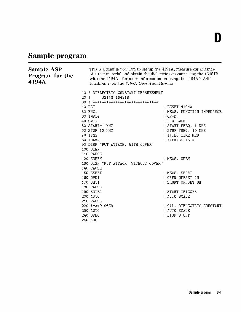
D
Sample program
Sample ASPProgram for the4194A
This is a sample program to set up the 4194A, measure capacitance
of a test material and obtain the dielectric constant using the 16451B
with the 4194A. For more information on using the 4194A's ASP
function, refer the 4194A Operation Manual.
10 ! DIELECTRIC CONSTANT MEASUREMENT
20 ! USING 16451B
30 ! *****************************
40 RST ! RESET 4194A
50 FNC1 ! MEAS. FUNCTION IMPEDANCE
60 IMP14 ! CP-D
40 SWT2 ! LOG SWEEP
50 START=1 KHZ ! START FREQ. 1 KHZ
60 STOP=10 MHZ ! STOP FREQ. 10 MHZ
70 ITM2 ! INTEG TIME MED
80 NOA=4 ! AVERAGE IS 4
90 DISP "PUT ATTACH. WITH COVER"
100 BEEP
110 PAUSE
120 ZOPEN ! MEAS. OPEN
130 DISP "PUT ATTACH. WITHOUT COVER"
140 PAUSE
150 ZSHRT ! MEAS. SHORT
160 OPN1 ! OPEN OFFSET ON
170 SHT1 ! SHORT OFFSET ON
180 PAUSE
190 SWTRG ! START TRIGGER
200 AUTO ! AUTO SCALE
210 PAUSE
220 A=A*9.96E9 ! CAL. DIELECTRIC CONSTANT
230 AUTO ! AUTO SCALE
240 DPB0 ! DISP B OFF
250 END
Sample program D-1

Sample Programfor the 4284A
This is a sample program for the HP 9000 series 300 Engineering
Workstation to set up and measure a test material and obtain the
dielectric constant using the 16451B with the 4284A via GPIB. For
more information to use the 4284A such as GPIB command, refer the
4284A Operation Manual.
1000 DIM Xp(20),Yp(20)
1010 DIM Work$[100]
1020 DIM Freq(20),A(2,20),B(2,20),D(20)
1030 DIM Axis(2,2),Axis$(2)[20]
1040 !
1050 Ix=1
1060 Iy=2
1070 Tg=2.5*10^(-3) ! Distance of gap
1080 Ta=2.01*10^(-3) ! Thickness of material
1090 Tr=Tg/Ta
1100 !
1110 Hp4284a=717 ! Address of 4284A
1120 ASSIGN @Work TO "WORK"
1130 READ Nfreq ! read number of frequency
1140 !
1150 FOR Ifreq=1 TO Nfreq
1160 READ Freq(Ifreq) ! read meas. frequency
1170 NEXT Ifreq
1180 !
1190 F_correct=0
1200 INPUT "Dose the correction required? (yes=1 no=0)",F_correct
1210 !
1220 ! * 4284A initialization *
1230 OUTPUT Hp4284a;"CORR:LENG 1M" ! Cable length 1 m
1240 OUTPUT Hp4284a;"TRIG:SOUR BUS" ! Bus trigger mode
1250 OUTPUT Hp4284a;"FUNC:IMP CSD" ! Ls-Rs maes. func.
1260 OUTPUT Hp4284a;"INIT:CONT ON"
1270 OUTPUT Hp4284a;"DISP:PAGE MEAS" ! Meas. page
1280 OUTPUT Hp4284a;"INIT" ! Initialize
1290 ! * Correction *
1300 IF F_correct=No THEN Skip_correct
1310 PRINT "Put the Attachment for OPEN correction"
1320 PAUSE
1330 OUTPUT Hp4284a;"CORR:OPEN" ! Execute OPEN
1340 OUTPUT Hp4284a;"STAT:OPER:EVEN?" ! Check meas. end
1350 ENTER Hp4284a;Event_reg
1360 IF BINAND(Event_reg,1)=0 THEN 1340
1370 PRINT "Change the Attachment for SHORT correction"
1380 PAUSE
1390 OUTPUT Hp4284a;"CORR:SHORT" ! Execute SHORT
1400 OUTPUT Hp4284a;"STAT:OPER:EVEN?" ! Check meas. end
1410 ENTER Hp4284a;Event_reg
1420 IF BINAND(Event_reg,1)=0 THEN 1400
1430 Skip_correct:
1440 OUTPUT Hp4284a;"CORR:OPEN:STAT 1" ! OPEN ON
1450 OUTPUT Hp4284a;"CORR:SHORT:STAT 1"! SHORT ON
1460 ! * Meas. routine *
1470 FOR Imeas=1 TO 2
D-2 Sample program

1480 IF Imeas=1 THEN PRINT "Remove the attachment, then press CONT."
1490 IF Imeas=2 THEN PRINT "Set test material on the electrode, then press
CONT."
1500 PAUSE
1510 FOR Ifreq=1 TO Nfreq
1520 OUTPUT Hp4284a;"FREQ "&VAL$(Freq(Ifreq))
1530 OUTPUT Hp4284a;"*TRG"
1540 ENTER Hp4284a;Work$
1550 A(Imeas,Ifreq)=VAL(Work$[1,12])
1560 NEXT Ifreq
1570 NEXT Imeas
1580 !
1590 PRINTER IS 701
1600 PRINT "Meas. Frequency Dielectric Const."
1610 FOR Ifreq=1 TO Nfreq
1620 D(Ifreq)=1/(1-(1-A(1,Ifreq)/A(2,Ifreq))*Tr)
1630 PRINT USING "D.DDESZZ,AAAAAA,D.DDDD"; Freq(Ifreq) ;"[Hz]"; D(Ifreq)
1640 NEXT Ifreq
1650 PRINTER IS CRT
1660 !
1670 OUTPUT @Work;Nfreq ! Store meas. condition
1680 FOR Ifreq=1 TO Nfreq
1690 OUTPUT @Work;D(Ifreq) ! Store meas. data
1700 NEXT Ifreq
1710 ! * Graphic initialize *
1720 CLEAR SCREEN ! Clear screen
1730 WINDOW -.5,2,-.5,2 ! Set graphic window
1740 Dmax=MAX(D(*)) ! Find max. value of meas. dat
1750 GOSUB Axis
1760 FOR Ifreq=1 TO Nfreq ! * Calc. graphic data *
1770 !
1780 Xp(Ifreq)=Freq(Ifreq)/Freq(Nfreq)
1790 Yp(Ifreq)=D(Ifreq)/Dmax
1800 !
1810 NEXT Ifreq
1820 MOVE Xp(1),Yp(1)
1830 FOR Ifreq=1 TO Nfreq
1840 DRAW Xp(Ifreq),Yp(Ifreq)
1850 NEXT Ifreq
1860 STOP
1870 !
1880 Axis:
1890 Axis$(1)="FREQ."
1900 Axis$(2)="Dielectric Constant"
1910 MAT Axis= (0)
1920 FOR Iax=1 TO 2
1930 Axis(Iax,Iax)=1.2
1940 NEXT Iax
1950 Xzero=0
1960 Yzero=0
1970 FOR Iax=Ix TO Iy
1980 MOVE Xzero,Yzero
1990 DRAW Axis(Iax,Ix),Axis(Iax,Iy)
2000 IF Iax=Ix THEN MOVE Axis(Iax,Ix)/2,Yzero-.1
2010 IF Iax=Iy THEN MOVE Xzero-.1,Axis(Iax,Iy)/2
Sample program D-3

2020 IF Iax=Ix THEN LORG 6
2030 IF Iax=Iy THEN LORG 4
2040 IF Iax=Iy THEN LDIR PI/2
2050 LABEL Axis$(Iax)
2060 NEXT Iax
2070 LDIR 0
2080 LORG 8
2090 MOVE .05,2/Dmax
2100 DRAW Xzero,2/Dmax
2110 LABEL "2"
2120 MOVE Xzero,Yzero
2130 LABEL "0"
2140 !
2150 LORG 6
2160 MOVE 1,.05
2170 DRAW 1,Yzero
2180 LABEL "1 M"
2190 RETURN
2200 ! * Meas. freq. data *
2210 DATA 10 ! Number of data
2220 DATA 1E4,2E4,5E4,1E5,2E5,3E5,4E5,5E5,7E5,1E6
2230 END
D-4 Sample program
E
Bibliography
ASTM Standards:D150-81,\Standard Test Method for A-C Loss
Characteristics and Permittivity (Dielectric Constant) of Solid
Electrical Insulating Materials", Annual Book of ASTM Standards,
Vol 10.02, July, 1987, pp.21-44.
Bibliography E-1

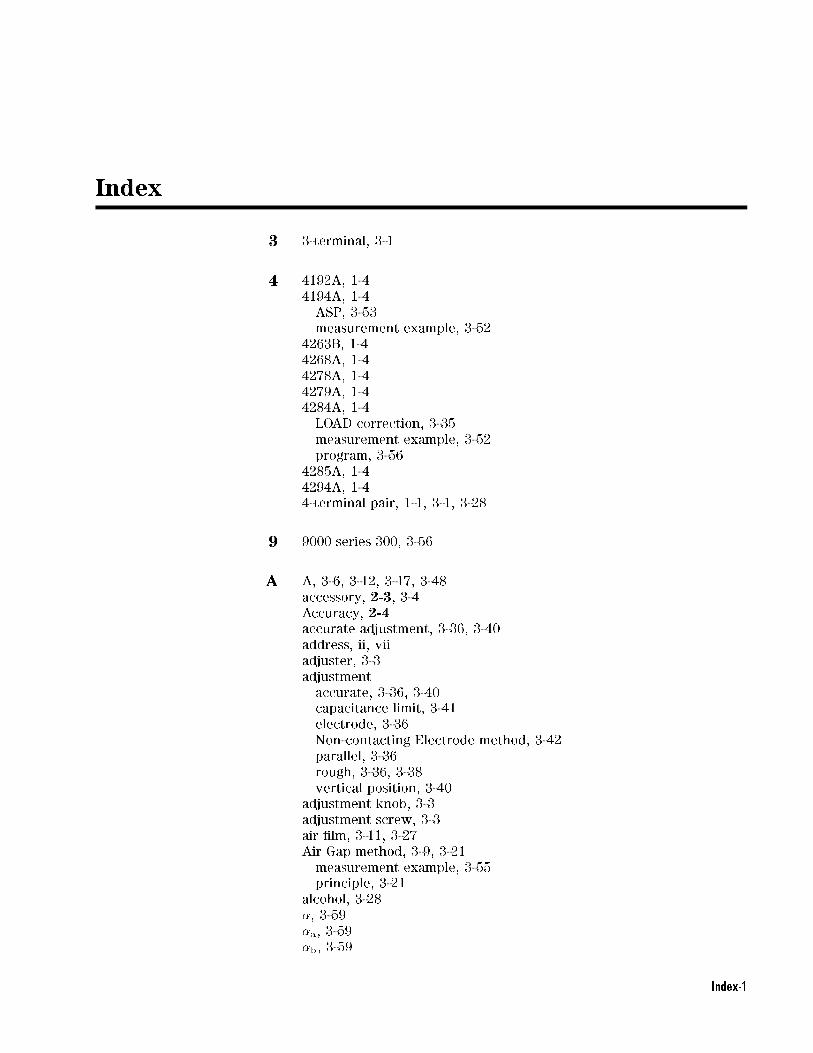
Index
3 3-terminal, 3-1
4 4192A, 1-4
4194A, 1-4
ASP, 3-53
measurement example, 3-52
4263B, 1-4
4268A, 1-4
4278A, 1-4
4279A, 1-4
4284A, 1-4
LOAD correction, 3-35
measurement example, 3-52
program, 3-56
4285A, 1-4
4294A, 1-4
4-terminal pair, 1-1, 3-1, 3-28
9 9000 series 300, 3-56
A A, 3-6, 3-12, 3-17, 3-48
accessory, 2-3, 3-4Accuracy, 2-4accurate adjustment, 3-36, 3-40
address, ii, vii
adjuster, 3-3
adjustment
accurate, 3-36, 3-40
capacitance limit, 3-41
electrode, 3-36
Non-contacting Electrode method, 3-42
parallel, 3-36
rough, 3-36, 3-38
vertical position, 3-40
adjustment knob, 3-3
adjustment screw, 3-3
air �lm, 3-11, 3-27
Air Gap method, 3-9, 3-21
measurement example, 3-55
principle, 3-21
alcohol, 3-28
�, 3-59
�a, 3-59
�b, 3-59
Index-1

angle, 4-3
Applicable voltage range, 2-3area
e�ective area, 3-59
ASP, 3-53
assembly, 4-1
Assistance, vii
ASTM, E-1
ASTM standards D150, 3-27
Attachment, 1-2
attachment for error correction, 3-5
attachment screw, 3-3, 3-28
average, 3-26
B Ba, 3-59
base, 4-5
basic
theory, 3-6
BASIC program, 3-56
Bb, 3-59
bias, 3-1
Bold, vi
bumper foot, 4-4
bushing, 4-5
C cable assembly, 3-1, 3-3, 4-4, 4-5, 4-6
cable compensation, 1-4
cable connection diagram, 4-9
Cable Length, 2-3cable length switch, 3-28
capacitance, 3-6
capacitance limit, 3-41
capacitance measurement error, 3-57, 3-62
carrying case, 3-5
Carrying Case, 1-2
Caution, ivCAUTION, 1-1
ccw, 3-28
changing electrode, 3-28
characteristics, 2-4
Cm, 3-63
compatible instrument, 1-4
error correction, 1-4
compensation, 1-4
compensation result example, 3-64
Computer, vi
conductive paint, 3-27
connecting, 3-28
Contacting Electrode method
measurement example, 3-52
procedure, 3-45
Contacting Electrode method (Rigid Metal electrode
principle, 3-11
Contacting Electrode method (Thin Film electrode
Index-2

principle, 3-16
contents, 1-2
copyright, ii
correction, 1-4, 3-30
for Electrode-A, 3-32
for Electrode-B, 3-32
for Electrode-C, 3-34
for Electrode-D, 3-34
for Rigid Metal electrode, 3-32
for Thin Film electrode, 3-34
LOAD, 3-35
OPEN, 3-30
SHORT, 3-32
correction function, 1-4
cover, 3-5, 4-3
cover bottom, 4-4
cover top, 4-4
Cp, 3-6, 3-12, 3-17, 3-48
Cs, 3-50
Cs1, 3-22
Cs2, 3-22, 3-50
cw, 3-30
D d, 3-6, 3-12, 3-17
D, 3-12, 3-17, 3-48
D1, 3-22, 3-50
D150, E-1
D2, 3-22, 3-50
dc bias, 3-1
demerit
Non-contacting Electrode method, 3-21
Rigid Metal, 3-11
Thin Film, 3-16
dent, 1-2
Description, 1-1
diameter, 2-9, 3-26
Electrode-A, 3-14, 3-24
Electrode-B, 3-15, 3-25
Electrode-C, 3-19
Electrode-D, 3-20
test material, 3-14, 3-15, 3-19, 3-20, 3-24, 3-25
tolerance, 3-58
dielectric, 3-6
dielectric constant, 2-1
relative dielectric constant, 2-1
dimensions, 2-9, 2-10
Dimensions, 2-7
disassembly, 4-1
dissipation factor, 3-7
Dr, 3-7
Dt, 3-12, 3-17, 3-22, 3-48, 3-57
Index-3
E edge, 3-8
e�ective area
table, 3-60
using Contacting Electrode method, 3-59
using Non-contacting Electrode method, 3-64
electrical trouble, 4-8
electric force, 3-8
electrode
38 mm Guarded/Guard electrode, 3-14
38 mm Guarded/Guard Electrode, 3-24
5 mm Guarded/Guard electrode, 3-15
5 mm Guarded/Guard Electrode, 3-25
adjustment, 3-36
changing, 3-28
diameter, 3-15, 3-19, 3-20, 3-24, 3-25
Diameter, 3-14
Electrode-A, 3-5, 3-14, 3-24
Electrode-B, 3-5, 3-15, 3-25
Electrode-C, 3-5, 3-19, 3-20
Electrode-D, 3-5
for Air Gap method, 3-23
for Contacting Electrode method, 3-18
for large thin �lm electrode, 3-19
for Non-contacting electrode, 3-23
for small thin �lm electrode, 3-20
for Thin Film electrode, 3-18
part number, 4-7
Thin Film electrode, 3-16
tolerance of diameter, 3-58
Electrode
Electrode-A, 1-2
Electrode-B, 1-2
Electrode-C, 1-2
Electrode-D, 1-2
for Contacting electrode method, 3-13
Rigid Metal electrode, 3-13
Unguarded electrode, 1-2
environment, iv
environmental limitations, 2-11
�, 3-6
�o, 3-6, 3-12, 3-17, 3-48
�r, 3-6, 3-12, 3-17, 3-22, 3-48, 3-57
equation, 3-6, 3-53, 3-56
Contacting Electrode method, 3-48
Contacting Electrode method (Rigid Metal), 3-12
Contacting Electrode method (Thin Film electrode), 3-17
Non-contacting Electrode method, 3-50
equivalent distance, 3-62
equivalent distance error, 3-62
Errata, 2-2
error
capacitance measurement error, 3-57, 3-62
compensation result example, 3-64
diameter, 3-58
e�ective area, 3-59, 3-64
Index-4

equivalent distance, 3-62
error analysis, 3-57
error factor, 3-57
atness, 3-58, 3-62
atness error, 3-27
gap, 3-58, 3-62
measurement error, 3-57
micrometer, 3-58, 3-62
parallelism, 3-58, 3-62
reduce gap error, 3-62
thickness, 3-58, 3-62
tolerance, 3-58
using Contacting Electrode method, 3-57
using Non-contacting Electrode method, 3-62
error correction, 3-30
evaporated metal, 3-27
example, 3-52
4194A, 3-52
4284A, 3-55
Air Gap method, 3-55
Contacting Electrode method, 3-52
Non-contacting Electrode method, 3-55
Rigid Metal electrode, 3-55
Thin Film electrode, 3-52
Exclusive Remedies, vi
F �lm, 3-26
�red on silver, 3-27
�xture assembly, 2-10, 3-1
atness
error, 3-58, 3-62
preparation, 3-27
for Contacting Electrode method, 3-9
for Non-contacting Electrode method, 3-9
frequency range, 2-3compatible instrument, 1-4
function, 2-3furnished accessory, 3-4
G g, 3-59
gap
between Guarded electrode and Guard electrode, 3-19, 3-20, 3-27
between Guarded/Guard electrode and Unguarded electrode, 3-58,
3-62
error, 3-58, 3-62
General Information, 2-1
glove, 3-28
GPIB, 3-56
Guarded/Guard electrode, 3-1, 3-3
Guard electrode, 3-8
Index-5

H Hardkey, vi
Hc, 3-3
hex key, 3-5
Hex key, 1-2
Hp, 3-3
humidity, 2-11
Humidity, 2-3
I IEC, 2-1
impedance analyzer, 1-1
incoming inspection, 1-1
Initial inspection, 1-2
Installation, 1-1
Introduction, 1-1
instrument
compatible, 1-4
compatible instrument, 1-4
frequency range, 1-4
insulator, 4-3
Italics, vi
L large knob, 3-3
Lc, 3-3
LCR meter, 1-1
limit
for adjustment, 3-41
lint free, 3-28
LOAD, 1-4
compensation, 3-35
correction, 3-35
loss tangent, 3-7
Lp, 3-3
M Manual
How to use, v
part number, iii
printing history, iii
Manual Change, 2-2
material, 2-9
measurement, 3-6
example, 3-52
method, 3-9
procedure, 3-45
mechanical trouble, 4-8
merit
Non-contacting Electrode method, 3-21
Rigid Metal, 3-11
Thin Film, 3-16
metal foil, 3-27
metal spattering, 3-27
method, 3-9Air Gap method, 3-21
error using Contacting Electrode method, 3-57
Index-6

error using Non-contacting Electrode method, 3-62
Non-contacting Electrode method, 3-21
procedure, 3-45
micrometer, 2-9, 3-1, 3-3, 4-3
error, 3-58, 3-62
replacement, 4-2
stand replacement, 4-2
missing contents, 1-2
N negative D, 3-35
Non-contacting Electrode method, 3-21
adjustment, 3-42
measurement example, 3-55
principle, 3-21
procedure, 3-49
Note, ivNOTE, 1-1
Notice, ii
O o�set, 3-30, 3-32
OPEN, 1-4, 3-30
OPEN circuit, 3-30
OPEN/SHORT/LOAD, 1-4
operation, 3-1
operation check, 4-8
overview, 1-2, 3-1
P packaging, 2-11
parallel
adjustment, 3-36
parallelism
error, 3-58, 3-62
part number, 1-2
performance, 2-3, 2-4
permittivity, 2-1
physical damage, 1-2
plate, 3-26, 4-3
plug hole, 4-5
preparation, 3-26preparing, 1-1
pressure adjuster, 3-3
principle
Contacting Electrode method (Rigid Metal electrode), 3-11
Contacting Electrode method (Thin Film electrode), 3-16
Non-contacting Electrode method (Air Gap method), 3-21
procedure, 3-45
Contacting Electrode method, 3-45, 3-46
Non-contacting Electrode method, 3-49
program, 3-53
Index-7
Q quantity, 1-2
R Range, 2-4ratchet knob, 3-3
relative dielectric constant, 2-1
repacking, 2-11
repair, vi, 1-2
replaceable parts list, 4-3
replacement, 1-2, 4-1
residual impedance, 3-30
resolution, 2-9
Rigid Metal electrode, 3-9
measurement example, 3-55
principle:, 3-11
rod, 4-5
rough adjustment, 3-36, 3-38
S Safety
summary, iv
symbol, iv
Safety Consideration, 2-1
scratch, 1-2
screw, 3-3, 3-28, 4-3, 4-4, 4-5, 4-6
Serial Number, 2-2
plate, 2-2
service, 4-1
shape
preparation, 3-26
SHORT, 1-4, 3-32
SHORT circuit, 3-32, 3-34
SHORT correction
for Rigid Metal electrode, 3-32
for thin �lm electrode, 3-34
slide stand, 4-1
slide stand assembly, 4-6
slightly compressible, 3-11
small knob, 3-3
smooth, 3-11
Softkey, vi
soft material, 3-21
spacer, 4-5, 4-6
Speci�cations, 2-3
sprayed metal, 3-27
spring, 4-5
standards, E-1
stopper, 4-4
storage, 2-11
stray admittance, 3-30
stray capacitance, 3-8
Supplemental Performance Characteristics, 2-4
surface, 3-27
Index-8

T t, 3-6, 3-22, 3-59
ta, 3-12, 3-17, 3-22, 3-48, 3-50
tan�, 3-7
temperature, 2-11
Temperature, 2-3Test Fixture, 1-2
test material
diameter, 3-14, 3-15, 3-19, 3-20, 3-24, 3-25, 3-26
atness, 3-27
for Electrode-A, 3-14, 3-24
for Electrode-B, 3-25
for Electrode-C, 3-19
for Electrode-D, 3-20
gap, 3-19, 3-20
preparation, 3-26
shape, 3-26
size for Electrode-B, 3-15
surface, 3-27
thickness, 3-14, 3-15, 3-19, 3-20, 3-24, 3-25, 3-26
Test Material, 2-9
test signal level, 3-1
tg, 3-50
theory, 3-6
thick, 3-11
thickness, 2-9
error, 3-58, 3-62
preparation, 3-26
test material, 3-14, 3-15, 3-19, 3-20, 3-24, 3-25
thin �lm, 3-5
Thin Film electrode, 3-9, 3-16
conductive paint, 3-27
evaporated metal, 3-27
�red on silver, 3-27
measurement example, 3-52
metal foil, 3-27
metal spattering, 3-27
preparation, 3-27
principle, 3-16
sprayed metal, 3-27
type, 3-27
tolerance, 3-58
trouble
electrical trouble, 4-8
mechanical trouble, 4-8
troubleshooting, 4-1, 4-8
tset;, 3-63
Typeface, vi
typical measurement, 3-45
Index-9

U �ta, 3-63
�te, 3-63
Unguarded electrode, 3-3, 4-3
V vertical position
adjustment, 3-40
capacitance limit, 3-41
visual inspection, 3-36
W Warning, iv, ivWARNING, 1-1
Warranty, vi
limitation, vi
washer, 4-3, 4-4, 4-6
Weight, 2-3working standard, 3-35
Z ZERO OPEN o�set, 3-30
ZERO SHORT o�set, 3-32
Index-10

This information is subject to change without notice.© Keysight Technologies 1989, 1992, 1993, 1999, 2000, 2014
Edition 6, November 2014
*16451-90020*16451-90020
www.keysight.com
Top Related