


Languages
Pages
Legal


Joachim SchultesUniversity of Wuppertal
Interlock SystemInterlock System
DCS Training Session 2.3DCS Training Session 2.3

DCS Training 2007: Interlock SystemJoachim SchultesJoachim Schultes
OverviewOverview
Interlock SystemInterlock System• StructureStructure• NumbersNumbers
ComponentsComponents• BBIM (Temperature Interlock, see session 1)BBIM (Temperature Interlock, see session 1)
• PP1 Box (Laser Interlock)PP1 Box (Laser Interlock)• BOC-I-Box (Laser Interlock)BOC-I-Box (Laser Interlock)
• Logic UnitsLogic Units
• Interlock Distribution BoxInterlock Distribution Box

DCS Training 2007: Interlock SystemJoachim SchultesJoachim Schultes
Interlock System (ATL-IP-ES-0110Interlock System (ATL-IP-ES-0110))
TemperatureTemperatureInterlockInterlock
LaserLaserInterlockInterlock

DCS Training 2007: Interlock SystemJoachim SchultesJoachim Schultes
Overview of Overview of Interlock SystemInterlock System

DCS Training 2007: Interlock SystemJoachim SchultesJoachim Schultes
User Interface and common User Interface and common
User InterfaceUser Interface• Shortcut on desktop (preferred)Shortcut on desktop (preferred)• Additional manager inside the PVSS consoleAdditional manager inside the PVSS console
Device Editor NavigatorDevice Editor Navigator• Use of the logical tabUse of the logical tab• Click on the entry opens the corresponding panelsClick on the entry opens the corresponding panels
General on Interlock Boxes:General on Interlock Boxes:• Channels are latchedChannels are latched
• Reset: reset the latches (preferred)Reset: reset the latches (preferred)• Transparent: no latching (debugging)Transparent: no latching (debugging)
• Colour code for each monitored output channel Colour code for each monitored output channel • Test signals for debuggingTest signals for debugging

DCS Training 2007: Interlock SystemJoachim SchultesJoachim Schultes
Laser Safety: PP1-Box and BOC-I-BoxLaser Safety: PP1-Box and BOC-I-Box
BOC-I-Box (one)BOC-I-Box (one)• InputsInputs
• 5 door switches of the Readout Racks5 door switches of the Readout Racks
• 2 x 4 I2 x 4 IPP1PP1 signals of PP1-Box signals of PP1-Box
• Interlock signals forInterlock signals for• 5 x 1 I5 x 1 IBOCBOC signal for the two BOC crates signal for the two BOC crates
inside the readout racks (local)inside the readout racks (local)
• IIPP1PP1 signals for the two BOC crates inside signals for the two BOC crates inside the readout racks (remote)the readout racks (remote)
• 5 I5 IBOCBOC signals for PP1-Box and LU signals for PP1-Box and LU
PP1-Box (one per counting room)PP1-Box (one per counting room)• inputsinputs
• IIDSSDSS (ATLAS Detector Safety System) (ATLAS Detector Safety System)
• 8 signals from PP1 micro switches8 signals from PP1 micro switches
• Interlock signals forInterlock signals for• 4 I4 IPP1PP1 signals for 14 LU (SC-OLink) signals for 14 LU (SC-OLink)

DCS Training 2007: Interlock SystemJoachim SchultesJoachim Schultes
User interface for PP1-Box and BOC-I-BoxUser interface for PP1-Box and BOC-I-Box
BOC-I-Box (one)BOC-I-Box (one)• Signals of 5 door switches from Signals of 5 door switches from
readout racksreadout racks
• 5 I5 IBOCBOC signals to PP1-Box signals to PP1-Box
• 2 x 4 I2 x 4 IPP1PP1 signals from PP1-Box signals from PP1-Box(US and USA)(US and USA)
PP1-Box (one per counting room)PP1-Box (one per counting room)• 8 I8 IPP1PP1 signals from PP1 switches signals from PP1 switches
• 4 I4 IPP1PP1 outputs to BOC-I-Box outputs to BOC-I-Box
• 5 I5 IBOCBOC signals from BOC-I-Box signals from BOC-I-Box
• 1 I1 IDSSDSS signal signal
• Channels are latchedChannels are latched• Reset: reset the latches (preferred)Reset: reset the latches (preferred)• Transparent: no latching (debugging)Transparent: no latching (debugging)

DCS Training 2007: Interlock SystemJoachim SchultesJoachim Schultes
Logic UnitLogic Unit
• one per Regulator Station one per Regulator Station (12 read out units)(12 read out units)
• ComponentsComponents• FPGA-BlockFPGA-Block
• 1 FPGA board1 FPGA board• 1 Wupp-ELMB1 Wupp-ELMB• 2 Latch boards2 Latch boards
• 3 T-Module blocks3 T-Module blocks• 1 Wupp-ELMB1 Wupp-ELMB• 2 Latch boards2 Latch boards
• 12 identical I-Matrix elements12 identical I-Matrix elements

DCS Training 2007: Interlock SystemJoachim SchultesJoachim Schultes
I-Matrix element of the Logic UnitI-Matrix element of the Logic Unit
• InputsInputs• 6(7) x I6(7) x IT_modulesT_modules 1 x I 1 x IT_highT_high
• 1 x I1 x IT_optoboardT_optoboard
• 7 x I7 x IT_PP2T_PP2
• 1 x I1 x IDSSDSS
• 1 x I1 x IBOCBOC
• 1 x I1 x IPP1PP1
• OutputsOutputs• 1 x I1 x IHVHV
• 1 x I1 x ILV_VddaLV_Vdda / I / ILV_VddLV_Vdd
• 1 x I1 x ISC-OLinkSC-OLink

DCS Training 2007: Interlock SystemJoachim SchultesJoachim Schultes
User interface for Logic UnitUser interface for Logic Unit
• Monitors input signals (dots)Monitors input signals (dots)• Channels are latchedChannels are latched
• Reset: reset the latches (preferred)Reset: reset the latches (preferred)• Transparent: no latching (debugging)Transparent: no latching (debugging)
• Disconnected status without InterlockDisconnected status without InterlockA good possibility to recognize disabled channels
InterlockInterlockDisabled channels Disabled channels (dipp switches)(dipp switches)
disconnecteddisconnected
InterlockInterlock
FPGA
resetreset
DCS Training 2007: Interlock SystemJoachim SchultesJoachim Schultes
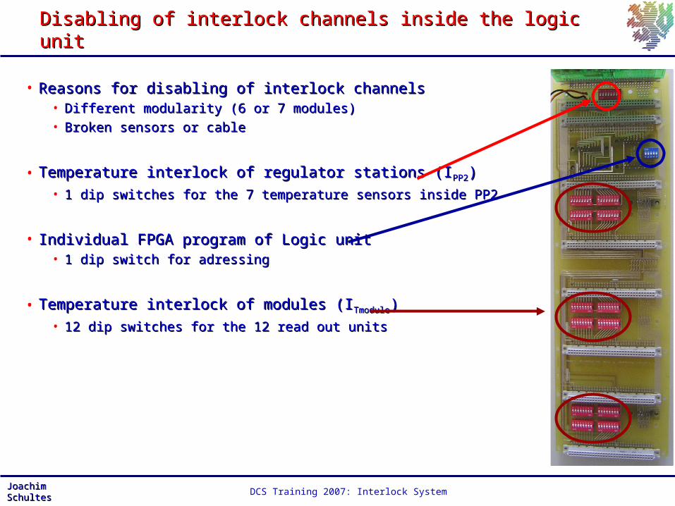
Disabling of interlock channels inside the logic unitDisabling of interlock channels inside the logic unit
• Reasons for disabling of interlock channelsReasons for disabling of interlock channels• Different modularity (6 or 7 modules) Different modularity (6 or 7 modules) • Broken sensors or cableBroken sensors or cable
• Temperature interlock of regulator stations (ITemperature interlock of regulator stations (IPP2PP2))• 1 dip switches for the 7 temperature sensors inside PP21 dip switches for the 7 temperature sensors inside PP2
• Individual FPGA program of Logic unitIndividual FPGA program of Logic unit• 1 dip switch for adressing1 dip switch for adressing
• Temperature interlock of modules (ITemperature interlock of modules (ITmoduleTmodule))• 12 dip switches for the 12 read out units12 dip switches for the 12 read out units

DCS Training 2007: Interlock SystemJoachim SchultesJoachim Schultes
Interlock Distribution Box: HV, LV and SC-OLinkInterlock Distribution Box: HV, LV and SC-OLink
Interlock Distribution Box:Interlock Distribution Box:• Aim: flexible mapping of Interlock Aim: flexible mapping of Interlock
signals to power supply channelssignals to power supply channels• Inputs for signals of 7 LUInputs for signals of 7 LU
(72 channels due to configuration)(72 channels due to configuration)• Channels are latchedChannels are latched
• Reset: reset the latches (preferred)Reset: reset the latches (preferred)• Transparent: no latching (debugging)Transparent: no latching (debugging)
IDB-HVIDB-HV• Responsible for 5 iseg modulesResponsible for 5 iseg modules• 5 x (2 x 8) Outputs5 x (2 x 8) Outputs
IDB-LVIDB-LV• Responsible for 6 Wiener cratesResponsible for 6 Wiener crates• 6 x 12 Outputs6 x 12 Outputs
IDB-SC-OLinkIDB-SC-OLink• Responsible for 5 SC-OLink cratesResponsible for 5 SC-OLink crates• 5 x (4 x 4) Outputs5 x (4 x 4) Outputs
Top Related