


Languages
Pages
Legal


NCDOT
PAVEMENT DESIGN PROCEDURE
AASHTO 1993 METHOD
N. C. Department of Transportation
Materials and Tests Unit – Pavement Section January 4, 2019

TABLE OF CONTENTS
INTRODUCTION ....................................................................................................................................................... 1
PAVEMENT DESIGN EQUATIONS ....................................................................................................................... 1
TRAFFIC ESALS ........................................................................................................................................................ 3
TERMINAL SERVICEABILITY INDEX ................................................................................................................ 4
RELIABILITY ............................................................................................................................................................ 5
LAYER COEFFICIENTS .......................................................................................................................................... 6
LOADING LEVELS (SUPERPAVE MIX DESIGNS) ............................................................................................ 7
UNIT WEIGHTS; APPLICATION RATES............................................................................................................. 7
ASPHALT CEMENT PERCENTAGES ................................................................................................................... 8
PAVEMENT LAYER DEPTHS ................................................................................................................................ 9
MINIMUM DEPTHS FOR PAVEMENT DESIGNS............................................................................................. 10
PAVEMENT DESIGNS FOR DETOURS .............................................................................................................. 10
THIN-DEPTH PAVED SHOULDER DESIGN ...................................................................................................... 10
BRIDGE REPLACEMENT PAVEMENT DESIGNS ........................................................................................... 10
RECOMMENED LOW VOUME PAVEMENT DESIGNS .................................................................................. 11
REHABILITATION DESIGNS ............................................................................................................................... 13
PAVEMENT DRAINAGE ........................................................................................................................................ 15
UNIT COSTS ............................................................................................................................................................. 16
APPROVED LIFE CYCLE COST ANALYSIS ..................................................................................................... 17
PAVEMENT TYPE SELECTION........................................................................................................................... 19
PRELIMINARY PAVEMENT DESIGNS .............................................................................................................. 19
FINAL PAVEMENT DESIGNS............................................................................................................................... 19
PAVEMENT REVIEW COMMITTEE .................................................................................................................. 20
FINAL PAVEMENT DESIGN LETTER ................................................................................................................ 20
ROADWAY DESIGN PAVED SHOULDER POLICY ......................................................................................... 21
QUICK CHECK LIST – FLEXIBLE DESIGNS ................................................................................................... 22

Page 1
INTRODUCTION
The pavement design guidelines included herein are to be used for the design of all new and rehabilitated projects in
North Carolina. This procedure will be updated as necessary to include new developments in design and analysis
procedures and will be distributed to Division Engineers and Pavement Review Committee members.
PAVEMENT DESIGN EQUATIONS
The AASHTO design equations as presented in the AASHTO Interim Guide for Design of Pavement Structures,
1993 are to be used for the design of both flexible and rigid pavements.
Flexible Pavement Designs
1993 Flexible Design Equation
log(W18) = Z𝑅 ∗ 𝑆𝑜 + 9.36 ∗ log(SN + 1) − 0.20 +log [
∆𝑃𝑆𝐼4.2 − 1.5
]
0.40 +1094
(𝑆𝑁 + 1)5.19
+ 2.32 ∗ log(𝑀𝑅) − 8.07
W18 = predicted number of 18-kip equivalent single axle load applications
ZR = standard normal deviate
So = combined standard error of the traffic prediction and performance prediction
ΔPSI = difference between the initial design serviceability index, po, and the design terminal
service index, pt
MR = resilient modulus (psi)
SN = structural number required of the total pavement thickness. Design SN must be within 0.10
of this SN Required.
The following inputs are used for flexible pavement design:
Design period = 30 years*
*A 20 year design is to be used on secondary roads with the ADT is less than 20,000 and
no LCCA is needed.
po = 4.20
pt = see Terminal Serviceability (pg. 4)
So = 0.45
ZR = see Reliability (pg. 5)
MR = if no resilient modulus is available use following equation to convert CBR values
𝑀𝑅 = 2555 ∗ (𝐶𝐵𝑅 𝑉𝐴𝐿𝑈𝐸)0.64

Page 2
Rigid Pavement Designs
1993 Rigid Design Equation
log(W18) = Z𝑅 ∗ 𝑆𝑜 + 7.35 ∗ log(D + 1) − 0.06 +log [
∆𝑃𝑆𝐼4.5 − 1.5
]
1 +1.624 ∗ 107
(𝐷 + 1)8.46
+ (4.22 − 032 ∗ 𝑝𝑡)
∗ log[𝑆𝑐
′ ∗ 𝐶𝑑 ∗ (𝐷0.75 − 1.132)
215.63 ∗ 𝐽 [𝐷0.75 −18.42
(𝐸𝑐/𝑘)0.25]]
W18 = predicted number of 18-kip equivalent single axle load(ESALS) applications
ZR = standard normal deviate
So = combined standard error of the traffic prediction and performance prediction
D = thickness (inches) of pavement slab
ΔPSI = difference between the initial design serviceability index, po, and the design terminal
service index, pt
S’c = modulus of rupture (psi) for Portland cement concrete used on a specific project
J = load transfer coefficient used to adjust for load transfer characteristics of a specific design
Cd = drainage coefficient
Ec = modulus of elasticity (psi) for Portland cement concrete
K = modulus of subgrade reaction.
The following inputs are used for concrete pavement design:
Design period = 30 years
po = 4.50
pt = see Terminal Serviceability (pg. 4)
So = 0.30
ZR = see Reliability (pg. 5)
J = 2.8 (tied PCC shoulders) or 3.2 (asphalt or RCC shoulders) If outside lanes are widened to 13’
a value of 2.8 can be used with any shoulders.
E = 3,500,000 psi
K = 400 psi/in (drainage layer on stabilized subgrade) or 200 psi/in (ABC)
Cd = 1.0
S’c = 650 (psi)

Page 3
TRAFFIC ESALS
The following traffic information is required for all pavement designs:
Initial ADT Percent Duals
Projected ADT Percent TTST
If the traffic forecast is more than 2 years old check to see if updated traffic information is available from the Traffic
Forecasting Unit. The projected ADT is normally for a 20-year period, although 30-year projections are needed for
pavement design and life cycle cost analyses. Unless the Traffic Forecast Unit provides 30-year projections, the 20-
year growth rate should be used to project traffic counts to the 30-year mark. The minimum growth rate used for
designs is 2.0%, unless the Traffic Forecast Unit provides a lower rate. Traffic loadings are expressed in terms of 18
kip equivalent single axle loads (ESALs) in the AASHTO design equations. Truck weight studies are used to
determine "average" loadings for two different truck classifications - Duals and TTST. The term "Duals" represents
single unit single axle trucks whereas the term "TTST" represents various combinations of multiple unit and
multiple axle trucks. Loadings from automobiles are considered to be negligible. Design values of 2% Duals and
TTST 1% are considered minimums. Equations for growth rates and ESALS are listed below.
%𝐺𝑟𝑜𝑤𝑡ℎ = (10^(
log10(𝐴𝐷𝑇𝐹𝑢𝑡𝑢𝑟𝑒 𝐴𝐷𝑇𝐼𝑛𝑖𝑡𝑖𝑎𝑙
)
(𝑌𝑒𝑎𝑟𝐹𝑢𝑡𝑢𝑟𝑒−𝑌𝑒𝑎𝑟𝐼𝑛𝑖𝑡𝑖𝑎𝑙 )∗365.25)
∗ 365.25 − 365.25) ∗ 100
𝐴𝐷𝑇𝐶 = 𝐴𝐷𝑇𝐼𝑛𝑖𝑡𝑖𝑎𝑙 ∗ (1 +%𝐺𝑟𝑜𝑤𝑡ℎ
100 ∗ 365.25)^((𝑌𝑒𝑎𝑟𝐶𝑜𝑛𝑠𝑡𝑟𝑢𝑡𝑖𝑜𝑛−𝑌𝑒𝑎𝑟𝐼𝑛𝑡𝑖𝑎𝑙)∗365.25)
𝐸𝑆𝐴𝐿𝑆𝑇𝑜𝑡𝑎𝑙 = ((1+
%𝐺𝑟𝑜𝑤𝑡ℎ
100∗365.25)(365.25∗𝑁𝐷)−1)∗(𝐴𝐷𝑇𝐶∗
%𝑇𝑇𝑆𝑇
100∗𝑇𝑇𝑆𝑇𝐹+𝐴𝐷𝑇𝐶∗
%𝐷𝑢𝑎𝑙𝑠
100∗𝐷𝑢𝑎𝑙𝐹)∗
%𝐷𝑖𝑟𝑒𝑐𝑡𝑖𝑜𝑛
100∗𝐿𝐷
ln(1+%𝐺𝑟𝑜𝑤𝑡ℎ
100∗365.25)
ND=Design Number of Years TTSTF= TTST Loading Factor
ADTC = Average Annual Daily Traffic in the year of construction. DualF = Duals Factor
Lane Distribution Factors (LD)
No. of Lanes
In One direction
Lane Distribution
Factor
1 1.0
2 0.9
3 or more 0.8
A lane distribution factor of 0.50 will be used for the design
of inside (median) lane widening of existing facilities with
2 or more lanes per direction.

Page 4
Truck Loading Factors
Flexible Pavement
18 kip ESALs
DUALS TTST
Rural Freeway & Interstates 0.30 1.15
Rural Other 0.30 0.95
Urban Freeway & Interstates 0.30 0.85
Urban Other 0.25 0.80
Rigid Pavement
18 kip ESALs
DUALS TTST
Rural Freeway & Interstates 0.30 1.60
Rural Other 0.35 1.30
Urban Freeway & Interstates 0.35 1.20
Urban Other 0.25 1.10
Rural – Any area that is mostly long distance trucks. (Typically this is outside city limits)
Urban – Any area that is mostly delivery area trucks. (Typically this is inside city limits or industrial area)
% Direction
A Direction spilt of 50% is typically used in all designs. Even if a different peak hour direction is given on
the plans, we assume that traffic throughout the day will equal 50% in each direction.
TERMINAL SERVICEABILITY INDEX
The terminal serviceability index (pt) represents the serviceability of a pavement at the end of the design period. The
Present Serviceability Rating (PSR) is based on a rating scale that designates the condition of the pavement at any
instant of time. This rating is the average rating of a panel of individuals who rate the pavement on a scale from 0 to
5.0. A rating of 5.0 indicates a "perfect" pavement, whereas a rating of 0 indicates an "impassable" pavement.
Selection of pt is based on the lowest serviceability that will be tolerated before surfacing or reconstruction becomes
necessary. A pavement with a terminal serviceability of 2.5 is considered the lowest acceptable rating for a major
highway. A terminal serviceability index (pt) of 2.75 will be used for roadways where the 20-year traffic projection
exceeds 40,000 ADT with a high heavy truck volume. A terminal serviceability index of 3.0 will be used for design
of all roadways where the 20-year traffic projection equals or exceeds 80,000 ADT with a high heavy truck volume.
A terminal serviceability index of 2.5 will be used for the design of all other roadways.
20 Year ADT Terminal Serviceability Index
80,000 or Larger 3.00
40,000 or Larger 2.75
Lowest Acceptable 2.50
Page 5
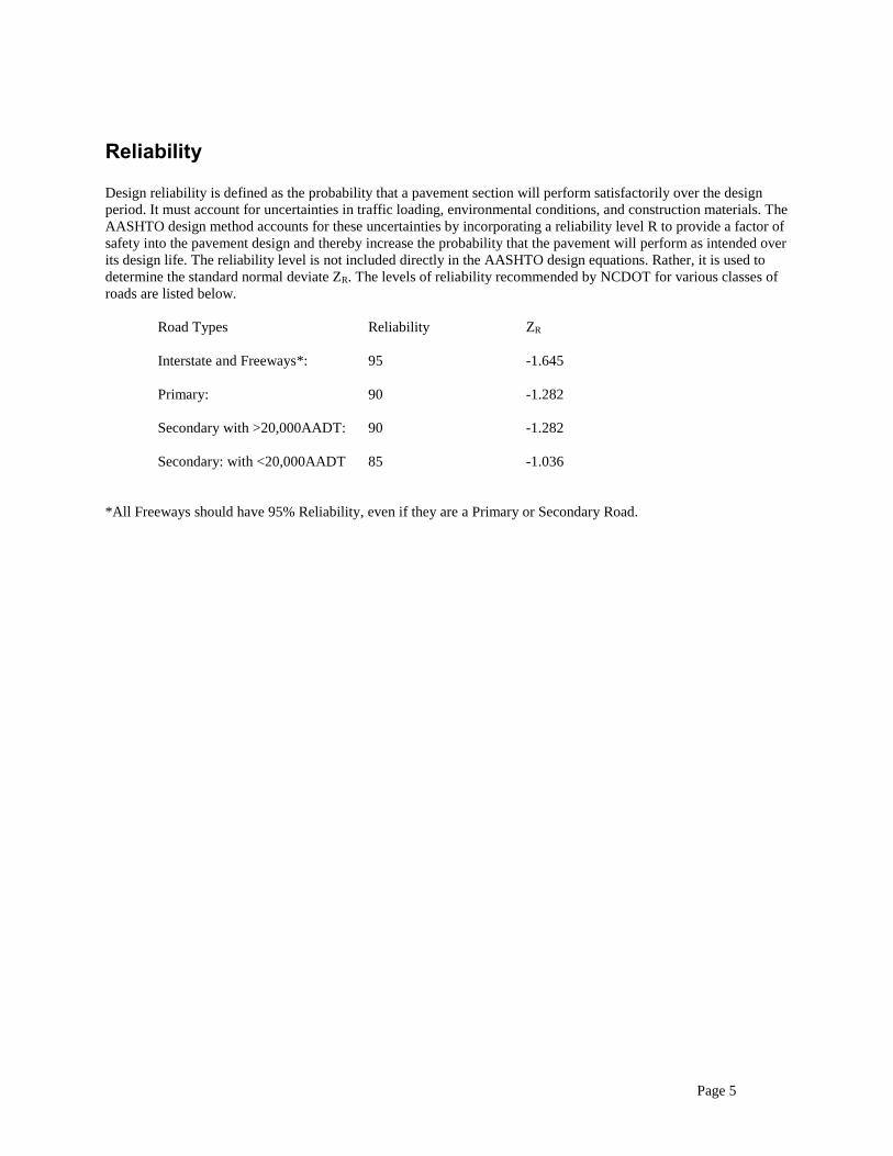
Reliability
Design reliability is defined as the probability that a pavement section will perform satisfactorily over the design
period. It must account for uncertainties in traffic loading, environmental conditions, and construction materials. The
AASHTO design method accounts for these uncertainties by incorporating a reliability level R to provide a factor of
safety into the pavement design and thereby increase the probability that the pavement will perform as intended over
its design life. The reliability level is not included directly in the AASHTO design equations. Rather, it is used to
determine the standard normal deviate ZR. The levels of reliability recommended by NCDOT for various classes of
roads are listed below.
Road Types Reliability ZR
Interstate and Freeways*: 95 -1.645
Primary: 90 -1.282
Secondary with >20,000AADT: 90 -1.282
Secondary: with <20,000AADT 85 -1.036
*All Freeways should have 95% Reliability, even if they are a Primary or Secondary Road.

Page 6
LAYER COEFFICIENTS
Layer coefficients used in building a new pavement structure to the required structural number (SN) are as follows:
Superpave Mix designs:
(per inch)
Asphalt Concrete Surface Course, Type S9.5X 0.44
Asphalt Concrete Intermediate Course, Type I19.0C 0.44
Asphalt Concrete Base Course, Type B25.0C 0.30
Other Materials:
Permeable Asphalt Drainage Course (PADC) 0.14
Aggregate Base Course (ABC) 0.14
Cement Treated Base Course (CTBC) 0.23
Cracked and Seated Concrete 0.28*
Rubblized Concrete 0.28*
Full Depth Reclaimed Asphalt 0.20*
(for layer)
200 mm (8") Lime Stabilized Subgrade 1.0
-or-
175 mm (7") Cement Stabilized Subgrade 1.0
* Monitoring of existing projects may result in changes to layer coefficients for crack and seat and rubblization.
LAYER COEFFICIENTS FOR EXISTING PAVEMENT
When calculating the structural number for existing pavements, the layer coefficients should be decreased to
determine the effective strength provide of the existing pavement. The amount of reduction is based on the surface
condition of the existing pavement. Suggested layer coefficients are given in the 1993 AASHTO Design Guide on
Table 5.2.

Page 7
LOADING LEVELS (Superpave Mix Designs)
The letter designation at the end of Superpave mix designs indicates the level of loading expected in a 20 year
design period. When designing for shorter durations, the selection of loading level should be based on the 20 year
accumulation of ESAL's.
The selection of asphalt binder grade for Superpave mixes is dependent on loading level. For surface mixtures, the
PG grade increases as a function of loading level.
Superpave loading designations and binder grade requirements are as follows.
Mix Type Loading Range
(20 Year Million ESAL's)
Asphalt Binder Grade
Surface
S9.5B Less than 3.0 PG64-22
S9.5C 3 to 30 PG64-22
S9.5D Over 30 PG76-22
Intermediate
I19.0C All PG64-22
Base
B25.0C All PG64-22
UNIT WEIGHTS; APPLICATION RATES Wt
Pavement Item lbs/sy-in.
S9.5B 110
S9.5C, S9.5D 112
I19.0C 114
B25.0C 114
PADC 90
ABC 150 Lbs./CF
CTBC (3.5% Cement) 150 Lbs./CF
Page 8
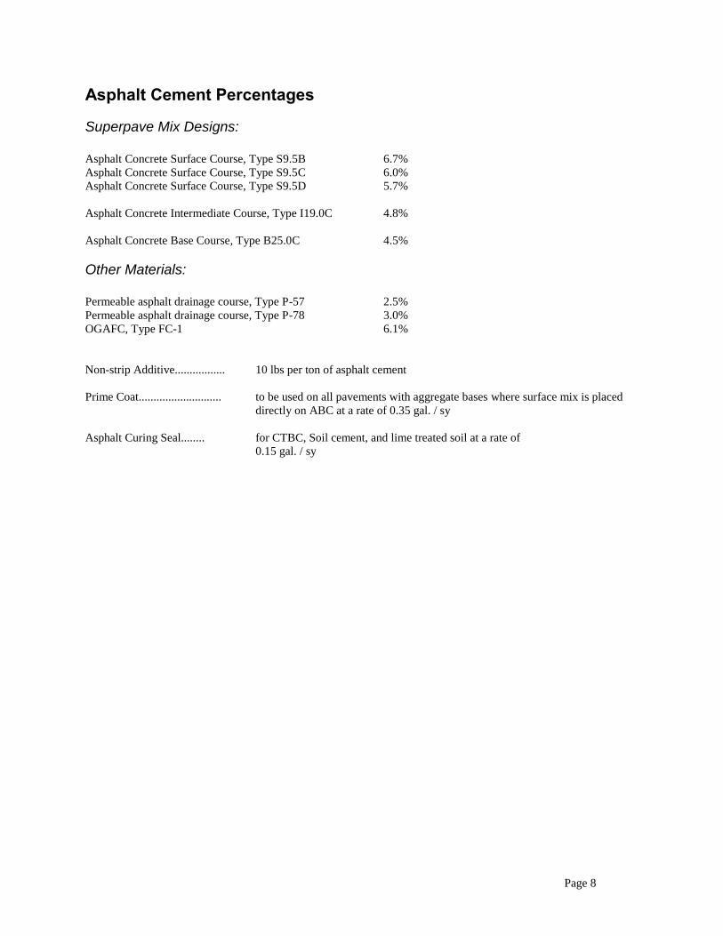
Asphalt Cement Percentages
Superpave Mix Designs:
Asphalt Concrete Surface Course, Type S9.5B 6.7%
Asphalt Concrete Surface Course, Type S9.5C 6.0%
Asphalt Concrete Surface Course, Type S9.5D 5.7%
Asphalt Concrete Intermediate Course, Type I19.0C 4.8%
Asphalt Concrete Base Course, Type B25.0C 4.5%
Other Materials:
Permeable asphalt drainage course, Type P-57 2.5%
Permeable asphalt drainage course, Type P-78 3.0%
OGAFC, Type FC-1 6.1%
Non-strip Additive................. 10 lbs per ton of asphalt cement
Prime Coat............................ to be used on all pavements with aggregate bases where surface mix is placed
directly on ABC at a rate of 0.35 gal. / sy
Asphalt Curing Seal........ for CTBC, Soil cement, and lime treated soil at a rate of
0.15 gal. / sy

Page 9
PAVEMENT LAYER DEPTHS
Max layer depths: Inches
S9.5X = 3.0
I19.0C = 4.0
B25.0C = no restrictions
ABC = normally limited to 12, recommended depths are typically 6*, 8, 10, and 12 inches.
*Typically Secondary Roads.
CTBC = 8 for plant mixed; for road mixed 8 with top 7 mixed.
Single lift depths: Inches
S9.5B = 1.0 to 1.5
S9.5C,D = 1.5* to 2.0
*1.0” may be used in wedging only
I19.0C = 2.5 to 4.0
B25.0C = 3.0* to 5.5
*For B25.0C placed on unstabilized subgrade, the minimum lift thickness is 4.0.
ABC = 6* to 10
*8” Preferred minimum on unstabilized subgrade for primary & greater roadways.
CTBC = 8
FDR = 12
Any deviations from these depths will be noted on the pavement design letter.
To "build" a structural number, as much of the structural number as possible will be put into the surface and
intermediate layers. In other words, the depths of these two layers will be maximized.
For normal mixes this total depth is 5-5.5 in, and for heavy duty designs the total depth is 6 in. 7 in. of
surface and intermediate depth is typically required on interstate designs.
For curb and gutter and expressway gutter sections, the total surface and intermediate depth will be
increased to 7 in. to match curb depth. For shoulder berm gutter sections, the total surface and intermediate
depth will be set to match gutter depth.
Two lifts of surface mix is standard for almost all designs. 1.25” or 1.5” of S9.5B and 1.5” of S9.5C/S9.5D
are the typical lift depths. An asphalt base, ABC base, or CTBC base is required on all flexible pavement
designs. Normally 8 in of ABC is used as the starting depth for aggregate base.
Prime Coat is required to be used where surface mixes is placed directly on top of ABC.
Page 10
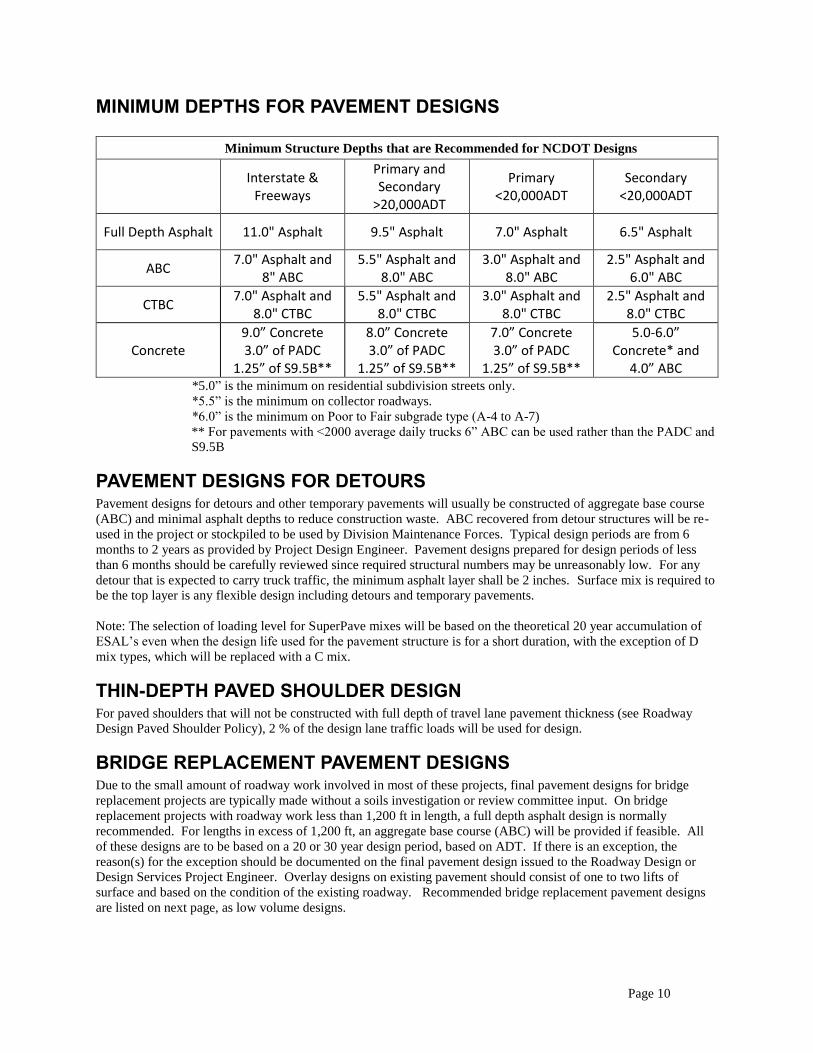
MINIMUM DEPTHS FOR PAVEMENT DESIGNS
Minimum Structure Depths that are Recommended for NCDOT Designs
Interstate & Freeways
Primary and Secondary
>20,000ADT
Primary <20,000ADT
Secondary <20,000ADT
Full Depth Asphalt 11.0" Asphalt 9.5" Asphalt 7.0" Asphalt 6.5" Asphalt
ABC 7.0" Asphalt and
8" ABC 5.5" Asphalt and
8.0" ABC 3.0" Asphalt and
8.0" ABC 2.5" Asphalt and
6.0" ABC
CTBC 7.0" Asphalt and
8.0" CTBC 5.5" Asphalt and
8.0" CTBC 3.0" Asphalt and
8.0" CTBC 2.5" Asphalt and
8.0" CTBC
Concrete 9.0” Concrete 3.0” of PADC
1.25” of S9.5B**
8.0” Concrete 3.0” of PADC
1.25” of S9.5B**
7.0” Concrete 3.0” of PADC
1.25” of S9.5B**
5.0-6.0” Concrete* and
4.0” ABC *5.0” is the minimum on residential subdivision streets only.
*5.5” is the minimum on collector roadways.
*6.0” is the minimum on Poor to Fair subgrade type (A-4 to A-7)
** For pavements with <2000 average daily trucks 6” ABC can be used rather than the PADC and
S9.5B
PAVEMENT DESIGNS FOR DETOURS Pavement designs for detours and other temporary pavements will usually be constructed of aggregate base course
(ABC) and minimal asphalt depths to reduce construction waste. ABC recovered from detour structures will be re-
used in the project or stockpiled to be used by Division Maintenance Forces. Typical design periods are from 6
months to 2 years as provided by Project Design Engineer. Pavement designs prepared for design periods of less
than 6 months should be carefully reviewed since required structural numbers may be unreasonably low. For any
detour that is expected to carry truck traffic, the minimum asphalt layer shall be 2 inches. Surface mix is required to
be the top layer is any flexible design including detours and temporary pavements.
Note: The selection of loading level for SuperPave mixes will be based on the theoretical 20 year accumulation of
ESAL’s even when the design life used for the pavement structure is for a short duration, with the exception of D
mix types, which will be replaced with a C mix.
THIN-DEPTH PAVED SHOULDER DESIGN For paved shoulders that will not be constructed with full depth of travel lane pavement thickness (see Roadway
Design Paved Shoulder Policy), 2 % of the design lane traffic loads will be used for design.
BRIDGE REPLACEMENT PAVEMENT DESIGNS Due to the small amount of roadway work involved in most of these projects, final pavement designs for bridge
replacement projects are typically made without a soils investigation or review committee input. On bridge
replacement projects with roadway work less than 1,200 ft in length, a full depth asphalt design is normally
recommended. For lengths in excess of 1,200 ft, an aggregate base course (ABC) will be provided if feasible. All
of these designs are to be based on a 20 or 30 year design period, based on ADT. If there is an exception, the
reason(s) for the exception should be documented on the final pavement design issued to the Roadway Design or
Design Services Project Engineer. Overlay designs on existing pavement should consist of one to two lifts of
surface and based on the condition of the existing roadway. Recommended bridge replacement pavement designs
are listed on next page, as low volume designs.

Page 11
RECOMMENED LOW VOUME PAVEMENT DESIGNS This table is an easy method to determine designs typically used for low volume pavements, based on
required SN (Page 1). Minimum pavement depths based on road types (page 10) still are required,
regardless of this table.
****CHECK DESIGN MEETS MINIUM DEPTHS FOR PAVEMENT DESIGNS (PAGE 10)****
Without Curb and Gutter Designs:
(Determine if load level is B, C, or D by using the 20 year ESALS - Page 7)
Table A-1 Recommended Pavement Design - (Full Depth)
Required Structural Number
Surface Inter. Base Structural Number Provided
B LEVEL DESIGNS (Use when 20 year ESALS are <0.3 Million)
<2.37 2.5” S9.5B 4.0” B25.0C 2.30
2.38 - 2.52 2.5” S9.5B 4.5” B25.0C 2.45
2.53 - 2.67 2.5” S9.5B 5.0” B25.0C 2.60
2.68 - 2.82 2.5” S9.5B 5.5” B25.0C 2.75
2.83 - 3.47 2.5” S9.5B 2.5” I19.0C 4.0” B25.0C 3.40
B, C, & D LEVEL DESIGNS (Use when 20 year ESALS are >0.3 Million)
<2.59 3.0” S9.5X 4.5” B25.0C 2.52
2.60 - 2.74 3.0” S9.5X 4.5” B25.0C 2.67
2.75 - 2.89 3.0” S9.5X 5.0” B25.0C 2.82
2.90 - 3.04 3.0” S9.5X 5.5” B25.0C 2.97
3.05 - 3.69 3.0” S9.5X 2.5” I19.0C 4.0” B25.0C 3.62
3.70 - 3.84 3.0” S9.5X 2.5” I19.0C 4.5” B25.0C 3.77
3.85 - 3.99 3.0” S9.5X 2.5” I19.0C 5.0” B25.0C 3.92
4.00 - 4.14 3.0” S9.5X 2.5” I19.0C 5.5” B25.0C 4.07
(Determine if load level is B, C, or D by using the 20 year ESALS - Page 7)
Table A-2 Recommended Pavement Design (ABC)
Required Structural Number
Surface Inter. Base Structural Number Provided
B LEVEL DESIGNS (Use when 20 year ESALS are <0.3 Million)
<2.01 2.5” S9.5B * 6” ABC 1.94
2.02 - 2.29 2.5” S9.5B* 8” ABC 2.22
2.30 - 2.57 2.5” S9.5B* 10” ABC 2.50
2.58 - 3.11 2.5” S9.5B 2.5” I19.0C 6” ABC 3.04
3.12 - 3.39 2.5” S9.5B 2.5” I19.0C 8” ABC 3.32
3.40 - 3.67 2.5” S9.5B 2.5” I19.0C 10” ABC 3.60
B, C, & D LEVEL DESIGNS (Use when 20 year ESALS are >0.3 Million)
<2.23 3.0” S9.5X 6” ABC 2.16
2.24 - 2.51 3.0” S9.5X 8” ABC 2.44
2.52 – 2.79 3.0” S9.5X 10” ABC 2.72
2.80 - 3.33 3.0” S9.5X 2.5” I19.0C 6” ABC 3.26
3.34 - 3.61 3.0” S9.5X 2.5” I19.0C 8” ABC 3.54
3.62 - 3.89 3.0” S9.5X 2.5” I19.0C 10” ABC 3.82
* Prime coat required
Page 12
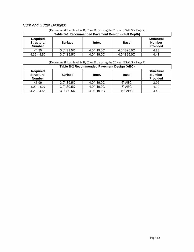
Curb and Gutter Designs:
(Determine if load level is B, C, or D by using the 20 year ESALS - Page 7)
Table B-1 Recommended Pavement Design - (Full Depth)
Required Structural Number
Surface Inter. Base Structural Number Provided
<4.35 3.0” S9.5X 4.0” I19.0C 4.0” B25.0C 4.28
4.36 - 4.50 3.0” S9.5X 4.0” I19.0C 4.5” B25.0C 4.43
(Determine if load level is B, C, or D by using the 20 year ESALS - Page 7)
Table B-2 Recommended Pavement Design (ABC)
Required Structural Number
Surface Inter. Base Structural Number Provided
<3.99 3.0” S9.5X 4.0” I19.0C 6” ABC 3.92
4.00 - 4.27 3.0” S9.5X 4.0” I19.0C 8” ABC 4.20
4.28 - 4.55 3.0” S9.5X 4.0” I19.0C 10” ABC 4.48

Page 13
REHABILITATION DESIGNS
Emphasis for rehabilitation designs is to be placed on structural evaluation of the existing pavement. In addition to
the normal investigation of these projects by the Geotechnical Unit, all pavement designs presented before the
Pavement Review Committee will require the following information:
1. Cores of existing pavement structure - to determine thickness of layers, assign structural layer coefficients, and
conduct laboratory tests as needed (typically one core for every five FWD test locations).
2. Temperature and FWD deflection data at least every 500 ft. in outside wheel path of outside lane to include all
core locations. If project is less than one mile in length, deflections are to be taken every 200 ft.
3. Dynamic Cone Penetrometer (DCP) evaluations to a minimum depth of 24 in. (through stone base, if present, and
into subgrade at core locations) as permitted by traffic control and safety considerations.
For rehabilitation designs requiring asphalt overlays, the design period will be 10 years. DCP, FWD, and lab test
data in addition to Geotechnical recommendations will be used to determine the existing soil support conditions.
Present and 10 year projected traffic figures are to be used to determine the number of 18 kip axle loads during the
design period and the required SN. With this information, three overlay thickness determinations may be prepared
as follows:
Design 1 - Condition Survey Method
The existing SN of the pavement is determined from the condition survey and core data. The overlay
thickness is determined from:
Overlay SN = Required SN - Existing SN
The existing SN will be determined by the pavement design engineer by assigning layer coefficients to the
pavement layers after examination of cores. DCP data will be utilized to determine the depth and layer
coefficient for aggregate base. Chapter 5 of the AASHTO Guide provides general guidelines for
assignment of layer coefficients based upon pavement surface distress. The layer SN is obtained by
multiplying the layer thickness by its assigned layer coefficient. The Existing SN is the sum of all layer
SN's in the pavement structure. The Required SN is the SN needed to support the 10 year projected traffic,
with the difference in these two structural numbers being the structural deficiency or overlay requirement.
Design 2 - Effective Structural Number
The effective structural number of the pavement structure will be determined from FWD data as outlined in
the Chapter 5 rewrite of the 1986 AASHTO Design Guide.
Effective SN = 0.0045*D*(Ep)^(1/3)
D = total depth of pavement structure (in.)
(total pavement depth above subgrade)
Ep = effective modulus of pavement layer (psi)
(from temperature corrected deflection data)
Overlay SN = Required SN - Effective SN

Page 14
Design 3 - Effective Modulus
The number of 18 kip axle loads during the 10 year design period is calculated and the target deflection is
determined from one of the following equations:
Dt = 10^((log(9.3*109/Wt18)/3.34)) (ABC)
or, Dt = 10^((log(5.6*1011/Wt18)/4.6)) (Full depth asphalt)
Dt = target FWD deflection (mils) (desired deflection limit),
Wt18 = number of 18 kip single axle load applications during the 10 year
design period
Deflection under the load plate is temperature corrected (currently requires air, pavement surface
temperature, and thickness of asphalt). The overall modulus of the entire pavement structure is determined
from the temperature corrected deflection by using the Boussinesq equation for a one layer structure:
Modulus = 2*1000*P*(1-µ2)/(ã* r *D0)
P = FWD load (lbs)
µ = Poisson's ratio
r = radius of loaded area (in.)
ã = 3.14159...
D0 = Temperature corrected deflection under load plate (mils)
For the FWD with a 5.905" (150 mm ) radius load plate and Poisson's ratio = 0.35 for the single layer, this
equation reduces to:
Modulus (psi) = 94.596*P ÷ D0
Now, by using Odemark's transformation for a 2 layer system, one can determine overlay thickness by
calculating the depth of 500,000 psi (3500 MPa) surfacing required to reduce the load plate deflection to
the target deflection. In this analysis, the following equation is solved for D:
Dt = 851,360*(D1+D2)
Dt = target deflection (mils)
D1 = 1/(Modulus*(1+((D/r)*((Ep/Modulus)^(1/3)))^2)^0.5)
D2 = (1-(1/((1+(D/r)^2)^0.5)))/Ep
r = FWD load plate radius = 5.9055 in. (150 mm).
Ep = 500,000 psi (overlay modulus)
D = overlay thickness (in.)
Modulus = overall pavement modulus (one layer modulus representing
entire pavement structure and subgrade) (psi)
All three design procedures may be evaluated by the Pavement Analysis Engineer for each project before providing
a design recommendation. Design method 3 is preferred due to larger statistical sample over full project length. In
order to accommodate clearance limitations under structures the design thickness may be reduced by utilizing
additives in the asphalt mix.

Page 15
PAVEMENT DRAINAGE
Drainage Sublayers
Rigid pavements will be constructed utilizing a Permeable Asphalt Drainage Layer (PADC) and an asphalt
separating layer under the concrete layer in order to provide uniform support and positive drainage, when Average
Daily Truck Traffic (ADTT) > 2000 trucks per day.
Shoulder Drains
Shoulder drains will be used continuously when permeable asphalt drainage layers are used. Shoulder drains will be
considered for all projects with average daily traffic (ADT) of 15,000 and heavy truck percent greater than 5%. For
projects with average daily traffic of 40,000 and heavy truck percent greater than 15%, shoulder drains are highly
recommended. Shoulder drains will typically be recommended for locations with flat grades (less than 1%), vertical
curves, and poorly draining soils. Aggregate shoulder drains are typically used in new projects. Geocomposite
shoulder drains may be used adjacent to existing pavements on rehabilitation projects.
Outlets
Outlets are generally located at 300’ intervals for the outside shoulders and 500’ for median shoulders. Wherever
possible, outlets are tied in to drainage structures. When outlets are placed on fill or ditch slopes, a concrete pad is
used to protect the end of the outlet pipe. Outlet locations are imprinted at the edge of concrete pavements and are
marked with red reflective pavement markers at the pavement edge on asphalt surfaces.
Page 16
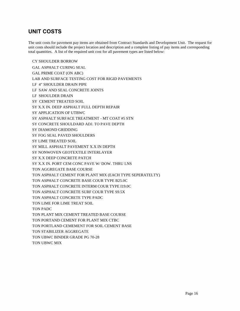
UNIT COSTS
The unit costs for pavement pay items are obtained from Contract Standards and Development Unit. The request for
unit costs should include the project location and description and a complete listing of pay items and corresponding
total quantities. A list of the required unit cost for all pavement types are listed below:
CY SHOULDER BORROW
GAL ASPHALT CURING SEAL
GAL PRIME COAT (ON ABC)
LAB AND SURFACE TESTING COST FOR RIGID PAVEMENTS
LF 4" SHOULDER DRAIN PIPE
LF SAW AND SEAL CONCRETE JOINTS
LF SHOULDER DRAIN
SY CEMENT TREATED SOIL
SY X.X IN. DEEP ASPHALT FULL DEPTH REPAIR
SY APPLICATION OF UTBWC
SY ASPHALT SURFACE TREATMENT - MT COAT #5 STN
SY CONCRETE SHOULDARD ADJ. TO PAVE DEPTH
SY DIAMOND GRIDDING
SY FOG SEAL PAVED SHOULDERS
SY LIME TREATED SOIL
SY MILL ASPHALT PAVEMENT X.X IN DEPTH
SY NONWOVEN GEOTEXTILE INTERLAYER
SY X.X DEEP CONCRETE PATCH
SY X.X IN. PORT CEM CONC PAVE W/ DOW. THRU LNS
TON AGGREGATE BASE COURSE
TON ASPHALT CEMENT FOR PLANT MIX (EACH TYPE SEPERATELTY)
TON ASPHALT CONCRETE BASE COUR TYPE B25.0C
TON ASPHALT CONCRETE INTERM COUR TYPE I19.0C
TON ASPHALT CONCRETE SURF COUR TYPE S9.5X
TON ASPHALT CONCRETE TYPE PADC
TON LIME FOR LIME TREAT SOIL
TON PADC
TON PLANT MIX CEMENT TREATED BASE COURSE
TON PORTAND CEMENT FOR PLANT MIX CTBC
TON PORTLAND CEMEMENT FOR SOIL CEMENT BASE
TON STABILIZER AGGREGATE
TON UBWC BINDER GRADE PG 70-28
TON UBWC MIX

Page 17
APPROVED LIFE CYCLE COST ANALYSIS • LCCA will be done for pavement projects greater than 1 mile in length for which initial traffic is greater
than 10,000 vehicles per day (vpd) and which are either reconstruction or are located on new location.
Expansion of use of LCCA to rehabilitation projects will require additional outreach to industry to
determine future treatments and their timing.
• A Present Worth Analysis with a 45 year analysis period is used. The discount rate shall be the 30-year
Real Treasury Interest Rate as provided in the Office of Management and Budget (OMB) Circular A-94
Appendix C. The average rate will be updated after the beginning of year OMB adjustment and that rate
will be used until the next year’s “beginning of year adjustment”.
• A 30-year design life will be used for the initial design for both flexible and rigid pavements. Subsequent
treatments are identified in the tables below.
• Flexible pavement alternates will include full depth asphalt, asphalt over dense graded aggregate (ABC)
and asphalt over cement treated aggregate base course (CTBC).
• For Average Daily Truck Traffic (ADTT) > 2,000 vehicles per day, concrete pavement alternatives will
include jointed concrete pavement with tied concrete shoulders and jointed concrete pavement with
widened (13’) outside lane with flexible shoulders. High truck volume concrete pavements will include a 3
inch drainage layer and a 1.25” asphalt separator layer.
• For pavements with less than 2,000 trucks per day, the concrete pavement will be placed on 6” of dense
graded ABC. These will use either a 12 foot lane width and asphalt shoulders or a 13 foot lane with a
reduced width asphalt shoulder, depending on cost.
• Subgrade Stabilization will be required when recommended by the Geotechnical Engineering Unit.
• Where the life of a treatment extends beyond the end of the analysis period, a salvage (remaining life) value
equal to the unused fraction of the expected life is subtracted at the end of the analysis period. For
example, for flexible pavement, additional thickness is added at year 34 to provide an additional 20 years of
life. At the end of the analysis period, this treatment will have 45% (9/20) of the value of the year 34
treatment as a salvage value.
• User costs will be calculated using FHWA software, Real Cost, to include user delay costs and the increase
in vehicle operating costs associated with work zone delays. User costs will be discounted and a Present
Worth Analysis will be conducted. User costs will be separate from the agency costs and user costs for
alternate pavement designs that are within 20% of each other will be considered equal. Calculation of user
cost is new for NCDOT, will require additional training and will be implemented by June 30, 2015.
• Agency cost LCCA will be considered equal between alternatives if the LCCA’s are within 10 percent.
• Selection criteria:
Regardless of the difference in LCCs, urban constructability will also be considered and will include the
impacts of utilities, curb and gutter, sidewalks, maintenance of traffic, etc.
1. If the calculated LCCs are within 10%, alternate bids may be considered. We will consider
adjacent pavement types with a goal of maintenance consistency for 3-mile segments. Impacts to
the public and to businesses will also be considered. Issues still remain with regard to FHWA
Technical Guidance on Alternate Bidding and NCDOT will not resume alternate bids until FHWA
concurs with our process.
2. If the difference in the LCCs is between 10% and 15%, we will consider division preference in
concurrence with the Chief Engineer. User costs will be considered if the user costs are different
by more than 20%. Note that the implementation date for user costs is June 30, 2015.
3. If the difference in the LCCs is greater than 15%, we will use the lowest LCC alternative unless
construction issues preclude its use. Issues will be documented in the project design file.
Page 18
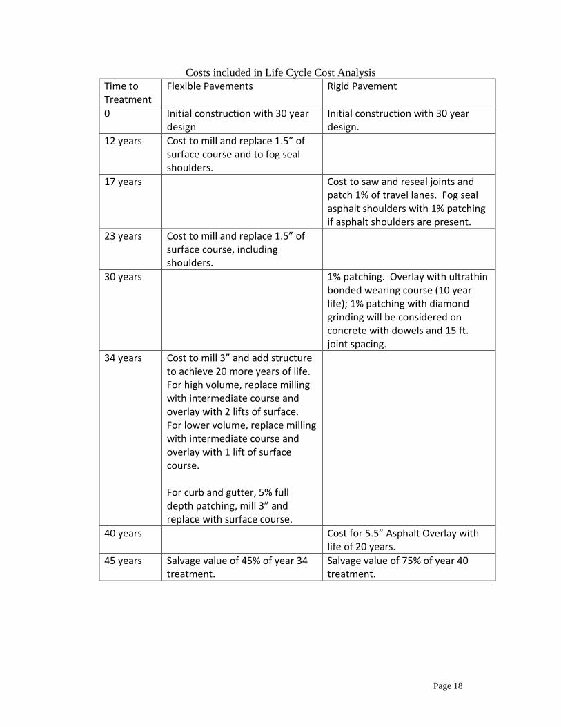
Costs included in Life Cycle Cost Analysis
Time to Treatment
Flexible Pavements Rigid Pavement
0 Initial construction with 30 year design
Initial construction with 30 year design.
12 years Cost to mill and replace 1.5” of surface course and to fog seal shoulders.
17 years Cost to saw and reseal joints and patch 1% of travel lanes. Fog seal asphalt shoulders with 1% patching if asphalt shoulders are present.
23 years Cost to mill and replace 1.5” of surface course, including shoulders.
30 years 1% patching. Overlay with ultrathin bonded wearing course (10 year life); 1% patching with diamond grinding will be considered on concrete with dowels and 15 ft. joint spacing.
34 years Cost to mill 3” and add structure to achieve 20 more years of life. For high volume, replace milling with intermediate course and overlay with 2 lifts of surface. For lower volume, replace milling with intermediate course and overlay with 1 lift of surface course. For curb and gutter, 5% full depth patching, mill 3” and replace with surface course.
40 years Cost for 5.5” Asphalt Overlay with life of 20 years.
45 years Salvage value of 45% of year 34 treatment.
Salvage value of 75% of year 40 treatment.

Page 19
PAVEMENT TYPE SELECTION
Many factors influence the decision making process for pavement type selection. The process will closely follow
the type selection guidelines as presented in Appendix B of the 1993 Guide for the Design of Pavement Structures.
Factors that influence the selection process include:
1. LCCA
2. Traffic,
3. Soils characteristics,
4. Weather,
5. Construction consideration,
6. Recycling,
7. Cost comparison,
8. Pavement performance,
9. Adjacent existing pavements,
10. Conservation of materials and energy,
11. Availability of local materials or contractor capabilities,
12. Traffic safety,
13. Incorporation of experimental features,
14. Stimulation of competition, and
15. Municipal preference, local government preference, and recognition of local industry.
PRELIMINARY PAVEMENT DESIGNS
Preliminary pavement designs will be prepared by the Pavement Design Engineer when requested by the Project
Design Engineer. These requests will normally be more than one year from the anticipated letting date. All
preliminary designs will specify ABC (aggregate base course) unless narrow widening (6 ft (1.8 m) or less) is
planned; in this case, a full depth asphalt design will be provided. The Roadway or Design Services Project
Engineer will be provided with a white sheet printout that will include all design input information, a required SN,
and a recommended pavement design. Designs for Y-lines, ramps, and shoulders may be summarized on the white
sheet.
FINAL PAVEMENT DESIGNS
Final pavement designs will be prepared upon receipt of the Geotechnical Report for the project. This should be no
later than 8 months prior to letting. LCCA will be done for pavement projects greater than 1 mile in length for
which initial traffic is greater than 10,000 vehicles per day (vpd) and which are either reconstruction or are located
on new location. Quantity estimates are to be prepared and submitted to the Estimating Management in the
Technical Services Unit for unit cost estimates. From these cost estimates, a per liner foot cost for the predominant
typical section is to be determined. Typical cost comparisons are to be made between full depth asphalt, aggregate
bases, and cement treated bases. For Average Daily Truck Traffic (ADTT) > 2000 trucks per day, concrete
pavement alternatives will be used including jointed concrete pavement with tied concrete shoulders and jointed
concrete pavement with widened (13’) outside lane with flexible shoulders.
Alternate pavement designs considered will be summarized in a "review sheet" for the project which will include
reasons for final pavement design recommendations. Emphasis on determining the recommended design is to be
placed on life cycle cost analyses. Reasons for recommendations by the pavement design engineer include but are
not limited to: initial construction cost, life cycle cost, performance history, traffic control, safety, and ease of
construction. Both initial and life cycle cost differences are not considered significant unless they exceed 10 %.
Designs will be presented and discussed at a monthly Pavement Review Committee meeting to aid the Pavement
Design Engineer in selecting the final pavement design. The LCCA will be verified 6 months before the let date to
make any updates with the unit costs. This is to insure that the alternate designs selection criteria has not been
affected by any updated unit cost.

Page 20
PAVEMENT REVIEW COMMITTEE
The Pavement Review Committee meets on the last Thursday of each month at 2:00 P.M. Target review dates at
least 12 to 15 months prior to schedule letting (turn in date for consultants). Members of the review committee
consist of representatives from the following units:
Construction
FHWA
Geotechnical
Materials and Test Pavement Section
STIP
Roadway Design
Traffic Management Unit/Work Zone Traffic Control
Invitations are extended to Division Engineers and/or their representatives for all projects.
EXECTIVE REVIEW COMMITTEE
For projects where the pavement type selection is difficult, unclear, or potentially controversial, the pavement type
selection made by the Pavement Review Committee will be reviewed by the Pavement Executive Committee,
consisting of the Chief Engineer, the Deputy Chief Engineer, and the Division Engineer from the Division in which
the project is located.
FINAL PAVEMENT DESIGN LETTER
After the Review Committee meeting, the State Pavement Management Engineer will furnish a final pavement
design letter to the Roadway or Design Services Project Engineer containing pavement designs for main line, Y-
lines, ramps, loops, collectors, service roads, paved shoulders and all other traffic bearing areas as needed.

Page 21
Roadway Design Paved Shoulder Policy

Page 22
Quick Check List – Flexible Designs
All input values used in the design equations are correct values.
Your design has 2 layers of surface if possible
Your design has an asphalt base, ABC, or CTBC layer
All layers are within the allowable minimum and maximum layer depths
The surface and intermediate layers all match the face of curb and gutter, if present on the project.
Correct loading levels are chosen for each pavement layer.
Minimum Structure Depths are meet for type of roadway.
Structure number of provided design meets the required structure number.
Thin-Depth paved shoulder design is provided if present on project.
Y-Line designs are provided if present on project.
Detour designs are provided if present on project.
Shoulder drains are provided if required on project.

Page 23
List of Revisions
Revision Date Description Editor
2-2-2018 Updated to reflect the mix consolidation changes in the 2018 QMS manual. ADW
9-6-2018 Updated to change the standard error of the rigid pavement design to 0.30. ADW
11-13-2018 Changed “CTABC” to “CTBC”. ADW
Top Related