


Languages
Pages
Legal


DMX UMD Manual page 1 rev 1.17
DMX-UMD
Integrated Step Motor
Encoder/Driver/Controller with
USB 2.0/RS-485 communication
DMX UMD Manual page 2 rev 1.17
COPYRIGHT © 2008 ARCUS,
ALL RIGHTS RESERVED
First edition, January 2008
ARCUS TECHNOLOGY copyrights this document. You may not
reproduce or translate into any language in any form and means any part of
this publication without the written permission from ARCUS.
ARCUS makes no representations or warranties regarding the content of this
document. We reserve the right to revise this document any time without
notice and obligation.
Revision History:
1.10 – 1st Release
1.15 – 2nd
Release
1.16 – 3rd
Release
1.17 – 4th
Release
Firmware Compatibility: †V230BL
†If your module’s firmware version number is less than the listed value, contact Arcus for the appropriate
documentation. Arcus reserves the right to change the firmware without notice.

DMX UMD Manual page 3 rev 1.17
Table of Contents
1. Introduction ..................................................................................................................... 7
Features ........................................................................................................................... 7
Model Numbers .............................................................................................................. 8
2. Electrical and Thermal Specifications ............................................................................ 9
Power Requirement ......................................................................................................... 9
Temperature Ratings † .................................................................................................... 9
Digital Inputs † ............................................................................................................... 9
Digital Outputs ................................................................................................................ 9
3. Dimensions ................................................................................................................... 10
4. Motor Specifications ..................................................................................................... 12
Electrical Specifications................................................................................................ 12
Torque Curve – NEMA 17 ........................................................................................... 12
Torque Curve – NEMA 23 ........................................................................................... 13
5. Connections................................................................................................................... 15
4-Pin Connector (5.08mm) ........................................................................................... 15
14-Pin Connector (2mm) .............................................................................................. 15
DMX-UMD Interface Circuit ....................................................................................... 17
Digital Outputs .............................................................................................................. 18
Digital Inputs ................................................................................................................ 18
6. Getting Started .............................................................................................................. 19
Typical Setup ................................................................................................................ 19
Windows GUI ............................................................................................................... 20
Main Control Screen ..................................................................................................... 21
A. Status ................................................................................................................. 22
B. Control .............................................................................................................. 23
C. Digital Input / Output ........................................................................................ 24
D. DMX-A2-DRV Alarm ...................................................................................... 25
E. Product Information .......................................................................................... 25
F. Terminal ............................................................................................................ 25
G. Setup ................................................................................................................. 26
H. Standalone Program File Management ............................................................. 28
I. Standalone Program Editor ............................................................................... 29
J. Standalone Processing ...................................................................................... 29
K. Variable Status .................................................................................................. 30
M. On-the-fly Speed Change .............................................................................. 31
N. About................................................................................................................. 31
7. Motion Control Overview ............................................................................................. 32
Motion Profile ............................................................................................................... 32
On-the-fly Speed Change .............................................................................................. 33
Digital Inputs/Outputs ................................................................................................... 33
Motor Power ................................................................................................................. 34
Polarity .......................................................................................................................... 34
Positional Moves ........................................................................................................... 35
On-The-Fly Target Position Change ............................................................................. 35

DMX UMD Manual page 4 rev 1.17
Jogging .......................................................................................................................... 35
Stopping Motor ............................................................................................................. 35
Homing ......................................................................................................................... 35
Home Input Only (High speed only) ........................................................................ 36
Home Input and Z-index ........................................................................................... 36
Home Input Only (High speed and low speed) ......................................................... 37
Limit Only ................................................................................................................. 37
Z-index only .............................................................................................................. 38
Motor Position .............................................................................................................. 38
Motor Status .................................................................................................................. 38
Limit Inputs ................................................................................................................... 39
Latch Input .................................................................................................................... 39
StepNLoop Closed Loop Control ................................................................................. 40
Device Number ............................................................................................................. 42
Baud Rate Setting ......................................................................................................... 42
Sync Output .................................................................................................................. 43
Broadcasting over RS-485 ............................................................................................ 43
Response Type .............................................................................................................. 43
Micro-step Driver Configuration .................................................................................. 44
Over Temperature Alarm .............................................................................................. 45
Standalone Programming .............................................................................................. 46
Communication Time-out Feature (Watchdog) ............................................................ 47
Storing to Flash ............................................................................................................. 47
8. Communication – USB ................................................................................................. 48
USB Communication API Functions ............................................................................ 48
USB Communication Issues ......................................................................................... 49
9. Communication – RS-485 (ASCII) .............................................................................. 50
Communication Port Settings ....................................................................................... 50
ASCII Protocol.............................................................................................................. 50
10. Communication - DIO ................................................................................................ 51
DIO Latency.................................................................................................................. 51
Setting Up DIO Parameters .......................................................................................... 51
Examples ....................................................................................................................... 52
Using DIO ..................................................................................................................... 53
11. ASCII Language Specification ................................................................................... 55
Error Codes ................................................................................................................... 59
12. Standalone Language Specification ............................................................................ 60
; ..................................................................................................................................... 60
ABORTX ...................................................................................................................... 60
ABS ............................................................................................................................... 60
ACC .............................................................................................................................. 60
DEC............................................................................................................................... 61
DELAY ......................................................................................................................... 61
DI .................................................................................................................................. 61
DI[1-6] .......................................................................................................................... 62
DO ................................................................................................................................. 62

DMX UMD Manual page 5 rev 1.17
DO[1-2] ......................................................................................................................... 62
DRVIC .......................................................................................................................... 63
DRVIT .......................................................................................................................... 63
DRVMS ........................................................................................................................ 63
DRVRC ......................................................................................................................... 64
ECLEARX .................................................................................................................... 64
ECLEARSX .................................................................................................................. 64
ELSE ............................................................................................................................. 64
ELSEIF ......................................................................................................................... 64
END .............................................................................................................................. 65
ENDIF ........................................................................................................................... 66
ENDSUB....................................................................................................................... 66
ENDWHILE ................................................................................................................. 66
EO ................................................................................................................................. 67
EX ................................................................................................................................. 67
GOSUB ......................................................................................................................... 67
HLHOMEX[+ or -] ....................................................................................................... 68
HOMEX[+ or -] ............................................................................................................ 68
HSPD ............................................................................................................................ 68
IF ................................................................................................................................... 68
INC ................................................................................................................................ 69
JOGX[+ or -] ................................................................................................................. 69
LHOMEX[+ or -] .......................................................................................................... 69
LSPD ............................................................................................................................. 70
LTX ............................................................................................................................... 70
LTEX ............................................................................................................................ 70
LTPX............................................................................................................................. 71
LTSX............................................................................................................................. 71
MSTX ........................................................................................................................... 71
PX ................................................................................................................................. 71
PS .................................................................................................................................. 72
RW ................................................................................................................................ 72
RWSTAT ...................................................................................................................... 72
SCVX ............................................................................................................................ 72
SLX ............................................................................................................................... 73
SLSX ............................................................................................................................. 73
SSPDX .......................................................................................................................... 73
SSPDMX....................................................................................................................... 74
STOPX .......................................................................................................................... 74
STORE .......................................................................................................................... 74
SYNCFGX .................................................................................................................... 75
SYNOFFX .................................................................................................................... 75
SYNONX ...................................................................................................................... 75
SYNPOSX .................................................................................................................... 75
SYNSTATX .................................................................................................................. 76
SYNTIMEX .................................................................................................................. 76
DMX UMD Manual page 6 rev 1.17
SUB ............................................................................................................................... 76
V[0-99] .......................................................................................................................... 77
WAITX ......................................................................................................................... 77
WHILE .......................................................................................................................... 78
X .................................................................................................................................... 78
ZHOMEX[+ or -] .......................................................................................................... 79
ZOMEX[+ or -] ............................................................................................................. 79
13. Example Standalone Programs ................................................................................... 80
Standalone Example Program 1 – Single Thread ......................................................... 80
Standalone Example Program 2 – Single Thread ......................................................... 80
Standalone Example Program 3 – Single Thread ......................................................... 80
Standalone Example Program 4 – Single Thread ......................................................... 81
Standalone Example Program 5 – Single Thread ......................................................... 81
Standalone Example Program 6 – Single Thread ......................................................... 82
Standalone Example Program 7 – Multi Thread........................................................... 83
Standalone Example Program 8 – Multi Thread........................................................... 84
Appendix A: Speed Settings ............................................................................................. 85
Acceleration/Deceleration Range ................................................................................. 85
Acceleration/Deceleration Range – Positional Move ................................................... 86
DMX UMD Manual page 7 rev 1.17
1. Introduction
DMX-UMD is an integrated stepper controller + driver + motor motion product.
Communication to the DMX-UMD can be established over USB or RS-485. It is also
possible to download a stand-alone program to the device and have it run independent of
a host.
Windows and Linux drivers as well as sample source code are available to aid you in
your software development.
Features
DMX-UMD
- USB 2.0 communication
- RS-485 ASCII communication
• 9600, 19200, 38400, 57600, 115200 bps
- Digital IO communication
• 4 bit motion profile select inputs (DI3-DI6)
• One start motion input (DI1)
• One abort/clear motion input (DI2)
• One in position output (DO1)
• One error output (DO2)
- A/B/Z differential encoder inputs
• StepNLoop closed loop control (position verification)
- Opto-isolated I/O
• 6 x inputs
• 2 x outputs
• 1 x High speed position capture latch input
• +Limit/-Limit/Home inputs
- Homing routines:
• Home input only (high speed)
• Home input only (high speed + low speed)
• Limit only
• Z-index encoder channel only
• Home input + Z index encoder channel
- S-curve or trapezoidal acceleration profile control
- On-the-fly speed change
- 1000 line incremental encoder (4000 counts/rev with 4x quadrature decoding)
- Stepper driver
• 12-48 VDC
• 3.0 Amp max current setting (peak current)
• 2 to 500 micro-step setting
• 1 MHz max pulse support
- Stepper motor

DMX UMD Manual page 8 rev 1.17
• NEMA 17/23 motor sizes available in different stack sizes
• 1.8° step angle
Model Numbers
Contacting Support
For technical support contact: [email protected].
Or, contact your local distributor for technical support.
DMX-UMD- -
Motor Stack Size 2 – Double
3 – Triple
Motor Frame Size 17 – NEMA 17 Motor
23 – NEMA 23 Motor

DMX UMD Manual page 9 rev 1.17
2. Electrical and Thermal Specifications
Power Requirement
Regulated Voltage: +12 to +48 VDC
Current (Max): 3 A (peak)
Temperature Ratings †
Operating Temperature: -20°C to +80°C
Storage Temperature: -55°C to +150°C
† Based on component ratings
Digital Inputs †
Type: Opto-isolated NPN inputs
Opto-isolator supply: +12 to +24 VDC
Maximum forward diode current: 45 mA
† Includes limit, home and latch
Digital Outputs
Type: Opto-isolated open-emitter PNP outputs
Max voltage at emitter: +24 VDC
Max source current at 24VDC †90 mA
† A current limiting resistor is required
DMX UMD Manual page 10 rev 1.17
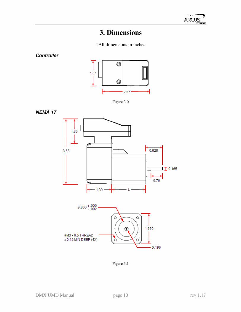
3. Dimensions
†All dimensions in inches
Controller
Figure 3.0
NEMA 17
Figure 3.1

DMX UMD Manual page 11 rev 1.17
NEMA 23
Figure 3.2
Model L (inches)
DMX-UMD-17-2 1.58
DMX-UMD-17-3 1.59
DMX-UMD-23-2 2.2
DMX-UMD-23-3 3.1
Table 3.0

DMX UMD Manual page 12 rev 1.17
4. Motor Specifications
Electrical Specifications
NEMA
Size
Stack
Size
Current /
Phase †
Holding
Torque
Resistance/
Phase
Inductance/
Phase
Inertia
17 Double 1.7A 0.44 N-m 1.5 Ω 3.0 mH 0.28 oz-in
2
Triple 2.0A 0.59 N-m 1.4 Ω 2.7 mH 0.37 oz-in2
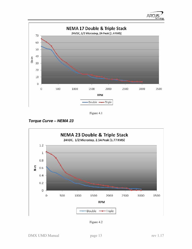
23 Double 2.8A 0.95 N-m 0.9 Ω 2.5 mH 1.64 oz-in
2
Triple 2.8A 1.41 N-m 1.13 Ω 3.6 mH 2.62 oz-in2
Table 4.0
† Motor current specifications are in RMS form.
Torque Curve – NEMA 17
Figure 4.0
DMX UMD Manual page 13 rev 1.17
Figure 4.1
Torque Curve – NEMA 23
Figure 4.2

DMX UMD Manual page 14 rev 1.17
Figure 4.3
DMX UMD Manual page 15 rev 1.17
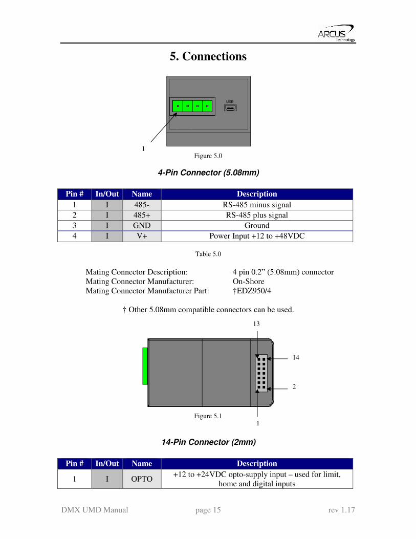
5. Connections
Figure 5.0
4-Pin Connector (5.08mm)
Pin # In/Out Name Description
1 I 485- RS-485 minus signal
2 I 485+ RS-485 plus signal
3 I GND Ground
4 I V+ Power Input +12 to +48VDC
Table 5.0
Mating Connector Description: 4 pin 0.2” (5.08mm) connector
Mating Connector Manufacturer: On-Shore
Mating Connector Manufacturer Part: †EDZ950/4
† Other 5.08mm compatible connectors can be used.
Figure 5.1
14-Pin Connector (2mm)
Pin # In/Out Name Description
1 I OPTO +12 to +24VDC opto-supply input – used for limit,
home and digital inputs
1
1
2
13
14
DMX UMD Manual page 16 rev 1.17
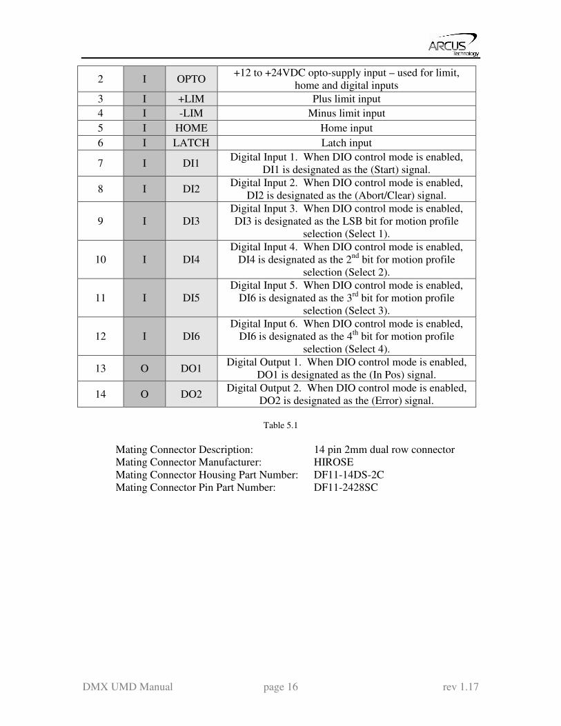
2 I OPTO +12 to +24VDC opto-supply input – used for limit,
home and digital inputs
3 I +LIM Plus limit input
4 I -LIM Minus limit input
5 I HOME Home input
6 I LATCH Latch input
7 I DI1 Digital Input 1. When DIO control mode is enabled,
DI1 is designated as the (Start) signal.
8 I DI2 Digital Input 2. When DIO control mode is enabled,
DI2 is designated as the (Abort/Clear) signal.
9 I DI3
Digital Input 3. When DIO control mode is enabled,
DI3 is designated as the LSB bit for motion profile
selection (Select 1).
10 I DI4
Digital Input 4. When DIO control mode is enabled,
DI4 is designated as the 2nd
bit for motion profile
selection (Select 2).
11 I DI5
Digital Input 5. When DIO control mode is enabled,
DI6 is designated as the 3rd
bit for motion profile
selection (Select 3).
12 I DI6
Digital Input 6. When DIO control mode is enabled,
DI6 is designated as the 4th
bit for motion profile
selection (Select 4).
13 O DO1 Digital Output 1. When DIO control mode is enabled,
DO1 is designated as the (In Pos) signal.
14 O DO2 Digital Output 2. When DIO control mode is enabled,
DO2 is designated as the (Error) signal.
Table 5.1
Mating Connector Description: 14 pin 2mm dual row connector
Mating Connector Manufacturer: HIROSE
Mating Connector Housing Part Number: DF11-14DS-2C Mating Connector Pin Part Number: DF11-2428SC
DMX UMD Manual page 17 rev 1.17
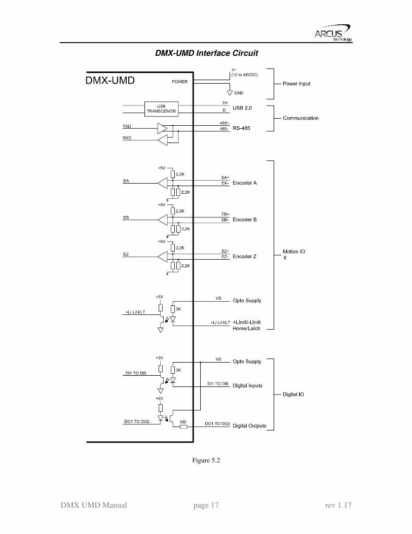
DMX-UMD Interface Circuit
Figure 5.2

DMX UMD Manual page 18 rev 1.17
Digital Outputs
Figure 5.3 shows an example wiring to the digital output.
Figure 5.3
WARNING: The maximum source current for digital outputs is 90 mA. Take caution to
select the appropriate pull-down resistance to limit the source current below this level.
Digital Inputs
Figure 5.4 shows the detailed schematic of the opto-isolated inputs.
Figure 5.4
DMX UMD Manual page 19 rev 1.17
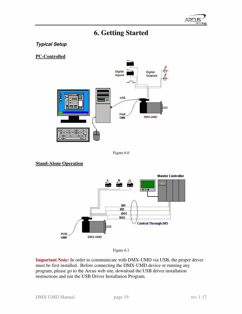
6. Getting Started
Typical Setup
PC-Controlled
Figure 6.0
Stand-Alone Operation
Figure 6.1
Important Note: In order to communicate with DMX-UMD via USB, the proper driver
must be first installed. Before connecting the DMX-UMD device or running any
program, please go to the Arcus web site, download the USB driver installation
instructions and run the USB Driver Installation Program.

DMX UMD Manual page 20 rev 1.17
Windows GUI
DMX-UMD comes with a Windows GUI program to test, program, compile, download,
and debug the controller.
Make sure that the USB driver is installed properly before running the controller.
Startup the DMX-UMD GUI program and you will see following screen.
Figure 6.2
A. Open USB Communication.
B. Open RS-485 communication.
C. If communication port or the baud rate is not known for RS-485, use these
buttons to search for the device.
A
B
C
DMX UMD Manual page 21 rev 1.17
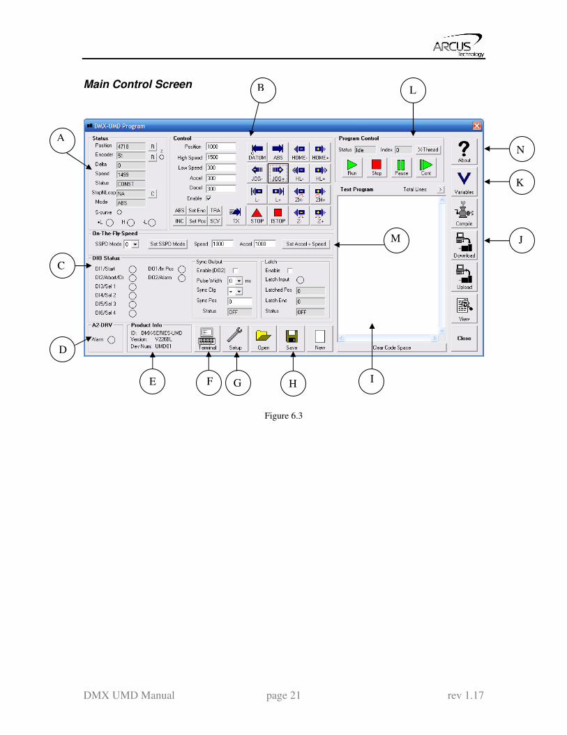
Main Control Screen
Figure 6.3
A
B
C
D
E F G H
J
I
L
K
M
N

DMX UMD Manual page 22 rev 1.17
A. Status
Figure 6.4
1. Pulse Counter – displays the current pulse position counter. When
StepNLoop is enabled, this displays the Target position.
2. Encoder Counter – displays the current encoder position counter.
3. Delta Counter – valid only for StepNLoop. Displays the difference between
the target position and the actual position.
4. Speed – displays the current pulse speed output rate. Value is in
pulses/second. While the controller is in StepNLoop mode, this value shows
encoder counts/second.
5. Motion Status – displays current motion status by displaying one of the
following status:
IDLE: motor is not moving
ACCEL: motion is in acceleration
DECEL: motion is in deceleration
CONST: motion is in constant speed
-LIM ERR: minus limit error
+LIM ERR: plus limit error
6. StepNLoop Status – valid only when StepNLoop is enabled and displays
current StepNLoop status by displaying one of the following:
NA: StepLNoop is disabled
IDLE: motor is not moving
MOVING: target move is in progress
JOGGING: jog move is in progress
HOMING: homing is in progress
LHOMING: limit homing in progress
Z-HOMING: homing using Z-index channel in progress
ERR-STALL: StepNLoop has stalled.
ERR-LIM: plus/minus limit error
7. Move Mode – displays current move mode
1
2
14
12
13
3
4
11
10
5
6
7
8
9

DMX UMD Manual page 23 rev 1.17
ABS: all the move commands by X[pos] command will be absolute
moves
INC: all the move commands by X[pos] command will be increment
moves.
8. S-curve Status – Displays whether the moves are in trapezoidal or S-curve
acceleration.
9. Limit/Home Input Status – Limit and Home input status.
10. Reset StepNLoop Error – When the StepNLoop status is in error, use this
button to clear the StepNLoop error. StepNLoop status will return to IDLE
after error is cleared.
11. Reset Status Error – When motion status is in error, use this button to clear
the error.
12. Reset Encoder Counter – Encoder counter can be reset to zero using this
botton.
13. Encoder Z Index Channel Status – Encoder Z index channel status is
displayed.
14. Reset Pulse Counter – Pulse counter can be reset to zero using this button.
B. Control
Figure 6.5
1. Target Position/Speed/Accel Position: use this to set the target position. For normal open loop
mode, this position is the pulse position and when StepNLoop is
enabled this target position is in encoder position.
High/Low Speed: use this to set the speed of the move. For normal
open loop mode, this value is in pulses/second and when StepNLoop is
enabled this value is in encoder counts/second
Accel: acceleration value in milliseconds
Decel:deceleration value in milliseconds
12
9 10
2
7 4
3
1
5 8 6
11
DMX UMD Manual page 24 rev 1.17
2. Enable Driver Power – use this button to enable and disable the power to the
micro-step driver.
3. Select Move Mode – use these buttons to select absolute or incremental move
mode.
4. Set Position – use these buttons to set the encoder or pulse position to
“Position” value
5. Select Acceleration Mode – use these buttons to select trapezoidal or S-curve
acceleration mode.
6. On-the-fly target change – Change the target position on-the-fly
7. Ramp Stop – use this button to stop the motion with deceleration.
8. Immediate Stop – use this button to stop the motion immediately. We
recommend that ramp stop be used whenever possible to reduce the impact to
the motor and the system.
9. Move back to zero – use this to move the motor to the zero target position.
When in absolute mode, the axis will move to zero position (zero encoder
position when in StepNLoop and zero pulse position when in open loop).
10. Perform Absolute Move – use this to move the motor to the target position.
When in absolute mode, the axis will move to the absolute target position.
When in incremental mode, the axis will move incrementally.
11. Jogging – jog motor in either positive or negative direction
12. Perform Homing – Five different homing routines are available
HOME: homing is done using only the home switch.
HL: homing is done using only the home switch at high speed and low
speed
L: homing is done using the limit switch
ZH: homing is done using the home switch first and then the Z index
channel of the encoder.
Z: homing is done only using the Z index channel of the encoder.
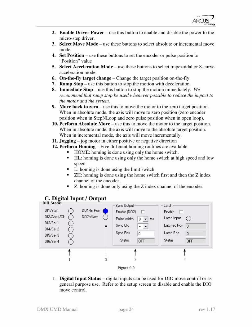
C. Digital Input / Output
Figure 6.6
1. Digital Input Status – digital inputs can be used for DIO move control or as
general purpose use. Refer to the setup screen to disable and enable the DIO
move control.
4 1 2 3

DMX UMD Manual page 25 rev 1.17
2. Digital Out Status and Control – digital outs are used for StepNLoop or
general purpose output use. When used as general purpose outputs, the
outputs can be triggered by clicking on the circle.
3. Sync Output – digital outputs can be triggered
4. Latch - encoder and pulse positions can be captured/latched with an input
trigger.
D. DMX-A2-DRV Alarm
Figure 6.7
Status of the DMX-A2-DRV driver alarm output signal is displayed.
E. Product Information
Figure 6.8
Product information and firmware version and device number is displayed.
Device number can be changed from the setup screen to support multiple
devices on the USB or RS-485 communication.
F. Terminal
Figure 6.9
Terminal dialog box allows manual testing of the commands from a terminal
screen as shown in Figure 6.9
DMX UMD Manual page 26 rev 1.17
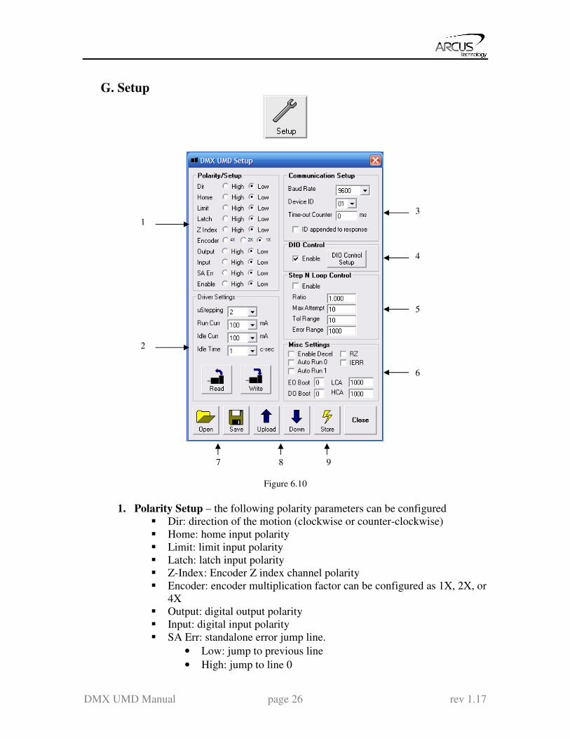
G. Setup
Figure 6.10
1. Polarity Setup – the following polarity parameters can be configured
Dir: direction of the motion (clockwise or counter-clockwise)
Home: home input polarity
Limit: limit input polarity
Latch: latch input polarity
Z-Index: Encoder Z index channel polarity
Encoder: encoder multiplication factor can be configured as 1X, 2X, or
4X
Output: digital output polarity
Input: digital input polarity
SA Err: standalone error jump line.
• Low: jump to previous line
• High: jump to line 0
1
2
3
5
4
6
7 8 9
DMX UMD Manual page 27 rev 1.17
Enable: enable output polarity
2. Driver Setting – The following driver settings can be configured:
Micro-step: 2 to 500 micro-steps
Run Current: 100mA to 3Amp
Idle Current: 100mA to 3Amp
Idle Time:1 to 100 centi-second (10 centi-second = 1 second)
3. Communication Setup RS-485 communication baud rate can be selected to support different
communication speed.
Device ID configuration allows multiple devices on the RS-485 or
USB communication network.
Time-out counter is a watch-dog timer for communication (ms)
ID append to response is used by RS-485 communication for adding
the device ID to any response.
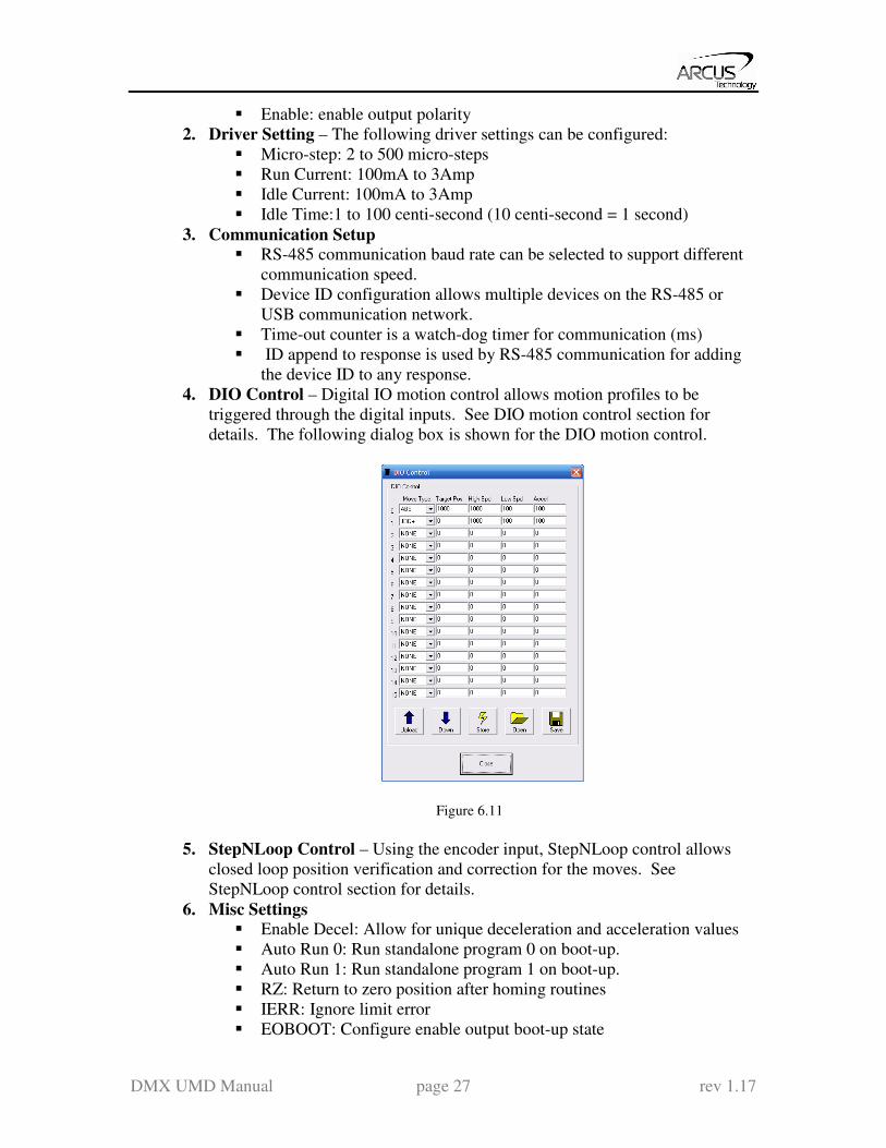
4. DIO Control – Digital IO motion control allows motion profiles to be
triggered through the digital inputs. See DIO motion control section for
details. The following dialog box is shown for the DIO motion control.
Figure 6.11
5. StepNLoop Control – Using the encoder input, StepNLoop control allows
closed loop position verification and correction for the moves. See
StepNLoop control section for details.
6. Misc Settings Enable Decel: Allow for unique deceleration and acceleration values
Auto Run 0: Run standalone program 0 on boot-up.
Auto Run 1: Run standalone program 1 on boot-up.
RZ: Return to zero position after homing routines
IERR: Ignore limit error
EOBOOT: Configure enable output boot-up state
DMX UMD Manual page 28 rev 1.17
DOBOOT: Configure digital output boot-up state
LCA: Set limit correction amount
HCA: Set home correction amount
7. Open/Save – Configuration values can be saved to a file and read from a file.
8. Upload/Download – Configuration values can be uploaded and downloaded.
Note that if the configuration values are changed, it needs to be downloaded to
take effect.
9. Store – The downloaded parameters can be permanently stored on the non-
volatile memory.
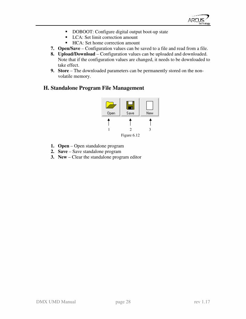
H. Standalone Program File Management
Figure 6.12
1. Open – Open standalone program
2. Save – Save standalone program
3. New – Clear the standalone program editor
1 2 3

DMX UMD Manual page 29 rev 1.17
I. Standalone Program Editor
Figure 6.13
1. Write the standalone program in the Program Editor
2. Use this button to remove the current standalone program
3. Use this button to open a larger and easier to manage program editor.
J. Standalone Processing
Figure 6.14
1. Compile – Compile the standalone program
1
2
3
4
1
1
2
3
DMX UMD Manual page 30 rev 1.17
2. Download – Download the compiled program
3. Upload – Upload the standalone program from the controller
4. View – View the low level compiled program
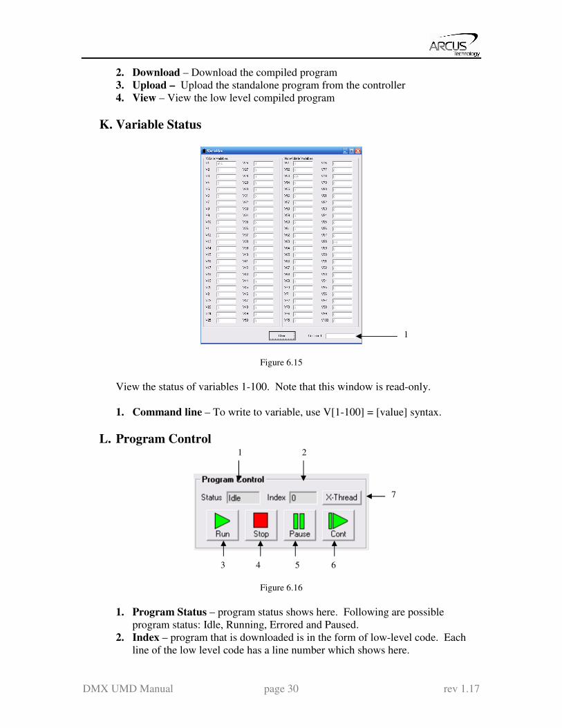
K. Variable Status
Figure 6.15
View the status of variables 1-100. Note that this window is read-only.
1. Command line – To write to variable, use V[1-100] = [value] syntax.
L. Program Control
Figure 6.16
1. Program Status – program status shows here. Following are possible
program status: Idle, Running, Errored and Paused.
2. Index – program that is downloaded is in the form of low-level code. Each
line of the low level code has a line number which shows here.
1
1
3 4 5 6
2
7

DMX UMD Manual page 31 rev 1.17
3. Run – program is run.
4. Stop – program is stopped.
5. Pause – program that is running can be paused.
6. Continue – program that is paused can be continued
7. X-Thread – Open the Program Control for standalone multi-thread operation.
M. On-The-Fly Speed Change Set the speed on the fly. On-the-fly speed change feature can only be used if the
controller is already in motion.
Figure 6.17
1. On-the-fly speed mode – Before setting the controller into motion, set the
SSPDM parameter. To see which value to use, see the on-the-fly speed
change section.
2. Set SSPDM – Set the SSPDM parameter. Note that if an on-the-fly speed
change operation is to be used, this parameter must be set before the controller
starts motion.
3. Desired Speed – Once the “Set Speed” button is clicked, the speed will
change on-the-fly to the desired speed.
4. Desired Acc/Dec – The acceleration/deceleration use for the on-the-fly speed
change operation.
5. Set Accel + Speed – Start the on-the-fly speed operation
N. About
Figure 6.18
Click this button to display the GUI version as well as the firmware version of the
controller/driver. If the firmware version is not up to date, the unsupported
features will be listed.
1 2 3 4 5

DMX UMD Manual page 32 rev 1.17
7. Motion Control Overview Important Note: All the commands described in this section are interactive commands
and are not analogous to stand-alone commands. Refer to the “Standalone Language
Specification” section for details regarding stand-alone commands.
Motion Profile
By default, a trapezoidal velocity profile is used. See Figure 7.0.
Figure 7.0
High speed and low speed are in pps (pulses/second). Use HSPD/LSPD commands to
modify the high speed and low speed settings.
Acceleration and deceleration time are in milliseconds. Use the ACC/DEC command to
modify the acceleration and deceleration values.
S-curve velocity profile can also be achieved by using the SCV command. See Figure
7.1.
Figure 7.1
Notes: By default, the deceleration is defined by the value set in the ACC parameter. In order to
decelerate using the value set in the DEC parameter, set EDEC to 1.
The minimum and maximum acceleration values depend on the high speed and low speed
settings. Refer to Table A.0 and Figure A.0 in Appendix A for details.

DMX UMD Manual page 33 rev 1.17
On-The-Fly Speed Change
On-the-fly speed change can be achieved with the SSPD command. In order to use the
SSPD command, s-curve velocity profile must be disabled.
SSPD Mode
The correct speed window must be selected in order to use the SSPD command. To
select a speed window, use the SSPDM command. Refer to Appendix A for details.
During on-the-fly speed change operation, you must keep the initial and destination
speeds within the speed window.
For non on-the-fly speed change moves, set SSPDM=0.
Digital Inputs/Outputs
DMX-UMD module comes with 6 digital inputs and 2 digital outputs which can be used
for DIO control. When DIO control is disabled, these can be used for general digital
output. Enable/disable DIO control mode by using the EDIO command.
Inputs
Read digital input status using the DI command.
Digital input values can also be referenced one bit at a time by the DI[1-6] commands.
Note that the indexes are 1-based for the bit references (i.e. DI1 refers to bit 0, not bit 1)
Bit Description Bit-Wise
Command
0 Digital Input 1 (Start) DI1
1 Digital Input 2 (Abort/Clear) DI2
2 Digital Input 3 (Select 1) DI3
3 Digital Input 4 (Select 2) DI4
4 Digital Input 5 (Select 3) DI5
5 Digital Input 6 (Select 4) DI6
Table 7.0
If digital input is on (i.e. input is pulled to GND of opto-supply), the bit status is 0.
Otherwise, the bit status is 1.
Outputs
When DIO control is disabled, you can drive DO1 and DO2 by using the DO command.
DO value must be within the range of 0-3.
Digital output values can also be referenced one bit at a time by the DO[1-2] commands.
Note that the indexes are 1-based for the bit references (i.e. DO1 refers to bit 0, not bit 1)
DMX UMD Manual page 34 rev 1.17
Bit Description Bit-Wise
Command
0 Digital Output 1 (In Position) DO1
1 Digital Output 2 (Alarm) DO2
Table 7.1
When DIO control is enabled, DO1 and DO2 are used as In Position and Alarm outputs.
If digital output is turned on (i.e. the output is pulled to VS), the bit status is 1. Otherwise,
the bit status is 0.
The initial state of both digital outputs can be defined by setting the DOBOOT register to
the desired value. The value is stored to flash memory using the STORE command.
Motor Power
Using the EO command, the motor power can be enabled or disabled. By default, the
enable output is turned off at boot-up.
The initial state of the enable output can be defined by setting the EOBOOT register to
the desired value. The value is stored to flash memory using the STORE command.
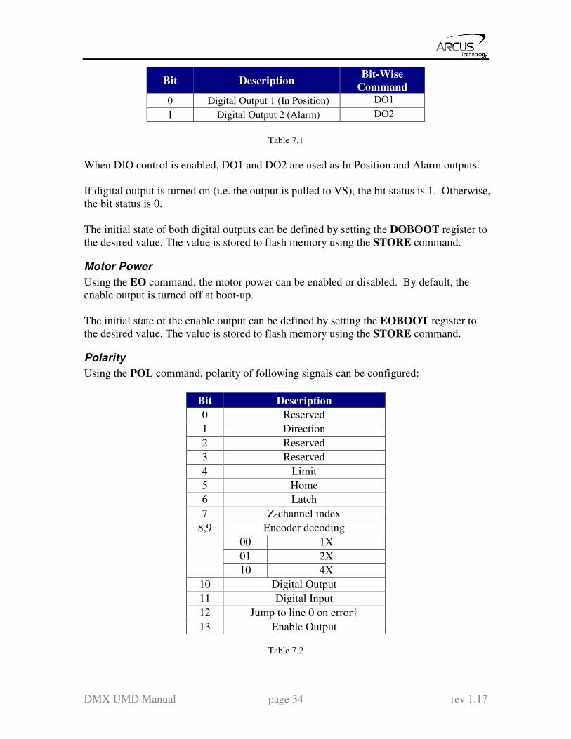
Polarity
Using the POL command, polarity of following signals can be configured:
Bit Description
0 Reserved
1 Direction
2 Reserved
3 Reserved
4 Limit
5 Home
6 Latch
7 Z-channel index
8,9 Encoder decoding
00 1X
01 2X
10 4X
10 Digital Output
11 Digital Input
12 Jump to line 0 on error†
13 Enable Output
Table 7.2

DMX UMD Manual page 35 rev 1.17
†Used for error handling within standalone operation. If this bit is on, the line that is
executed after SUB31 is called will be line 0. Otherwise, it will be the line that caused
the error.
Positional Moves
DMX-UMD can operate in either incremental or absolute move modes. Use X command
to make moves. Use INC and ABS commands change the move mode. Use MM
command to read the current move mode.
Note: If a motion command is sent while the controller is already moving, the command
is not processed. Instead, an error response is returned.
On-The-Fly Target Position Change
On-the-fly target position change can be achieved using the T[value] command. While
the motor is moving, T[value] will change the final destination of the motor. If the motor
has already passed the new target position, it will reverse direction once the target
position change command is issued.
Note: If a T command is sent while the controller is not performing a target move, the
command is not processed. Instead, an error response is returned.
Jogging
Jogging is available for continuous speed operation. Use J+ and J- commands to jog in
positive or negative direction.
Stopping Motor
When motor is moving, jogging, or homing, using the ABORT command will
immediately stop the motor. Using the STOP command will decelerate the motor to low
speed and then stop.
Homing
Home search sequence involves moving the motor towards the home or limit switches
and then stopping when the relevant input is detected. The DMX-UMD has 5 different
homing routines:

DMX UMD Manual page 36 rev 1.17
Home Input Only (High speed only) Use the H+/H- command. Figure 7.2 shows the homing routine.
Figure 7.2
A. Starts the motor from low speed and accelerates to high speed.
B. As soon as the home input is triggered, the position counter is reset to zero and
the motor begins to decelerate to low speed. As the motor decelerates, the
position counter keeps counting with reference to the zero position.
C. Once low speed is reached, the motor stops. The position is non-zero.
Home Input and Z-index Use the ZH+/ZH- command. Figure 7.3 shows the homing routine.
Figure 7.3
A. Issuing a limit home command starts the motor from low speed and accelerates to
high speed.
B. As soon as the home input is triggered, the motor decelerates to low speed
C. Once low speed is reached, the motor begins to search for the z-index pulse.
D. Once the z-index pulse is found, the motor stops and the position is set to zero.
DMX UMD Manual page 37 rev 1.17
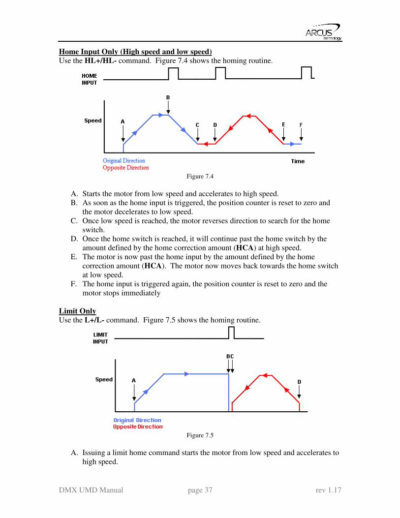
Home Input Only (High speed and low speed) Use the HL+/HL- command. Figure 7.4 shows the homing routine.
Figure 7.4
A. Starts the motor from low speed and accelerates to high speed.
B. As soon as the home input is triggered, the position counter is reset to zero and
the motor decelerates to low speed.
C. Once low speed is reached, the motor reverses direction to search for the home
switch.
D. Once the home switch is reached, it will continue past the home switch by the
amount defined by the home correction amount (HCA) at high speed.
E. The motor is now past the home input by the amount defined by the home
correction amount (HCA). The motor now moves back towards the home switch
at low speed.
F. The home input is triggered again, the position counter is reset to zero and the
motor stops immediately
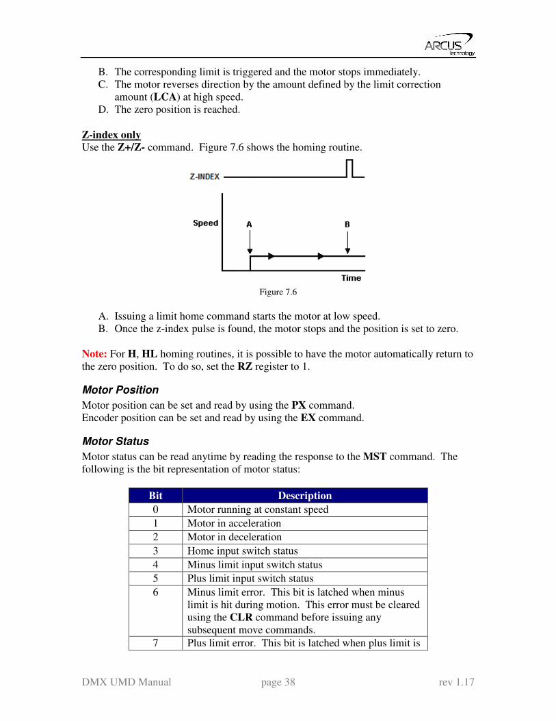
Limit Only Use the L+/L- command. Figure 7.5 shows the homing routine.
Figure 7.5
A. Issuing a limit home command starts the motor from low speed and accelerates to
high speed.
DMX UMD Manual page 38 rev 1.17
B. The corresponding limit is triggered and the motor stops immediately.
C. The motor reverses direction by the amount defined by the limit correction
amount (LCA) at high speed.
D. The zero position is reached.
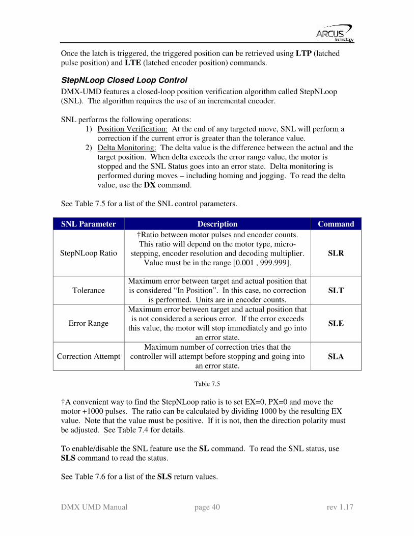
Z-index only Use the Z+/Z- command. Figure 7.6 shows the homing routine.
Figure 7.6
A. Issuing a limit home command starts the motor at low speed.
B. Once the z-index pulse is found, the motor stops and the position is set to zero.
Note: For H, HL homing routines, it is possible to have the motor automatically return to
the zero position. To do so, set the RZ register to 1.
Motor Position
Motor position can be set and read by using the PX command.
Encoder position can be set and read by using the EX command.
Motor Status
Motor status can be read anytime by reading the response to the MST command. The
following is the bit representation of motor status:
Bit Description
0 Motor running at constant speed
1 Motor in acceleration
2 Motor in deceleration
3 Home input switch status
4 Minus limit input switch status
5 Plus limit input switch status
6 Minus limit error. This bit is latched when minus
limit is hit during motion. This error must be cleared
using the CLR command before issuing any
subsequent move commands.
7 Plus limit error. This bit is latched when plus limit is

DMX UMD Manual page 39 rev 1.17
hit during motion. This error must be cleared using
the CLR command before issuing any subsequent
move commands.
8 Latch input status
9 Z-index status
10 TOC time-out status
Table 7.3
Examples:
- When motor status value is 0, motor is idle and all input switches are off.
- When motor status value is 2, motor is in acceleration.
- When motor status value is 9, motor is moving in constant high speed and
home input switch is on.
- When motor status value is 64, motor is in minus limit error. Use CLR
command to clear the error before issuing any more move commands.
Limit Inputs
If the positive limit switch is triggered while moving in the positive direction, the motor
will immediately stop and the status bit for the positive limit error is set. The same is for
the negative limit while moving in the negative direction. Once the limit error is set, use
the CLR command to clear the error. Once the error is cleared, move the motor out of
the limit switch.
The limit error state can be ignored by setting IERR=1. In this case, the motor will still
stop when the limit switch is triggered; however, it will not enter an error state.
Latch Input
The DMX-UMD module provides a high speed position latch input.
This input performs high speed position capture of both pulse and encoder positions but
does not reset the pulse or encoder position counters.
Note: When StepNLoop mode is enabled, the position value should be ignored.
Use the LT command to enable and disable latch feature. To read the latch status, use
LTS command.
Following are return value description for LTS command.
Return Value Description
0 Latch off
1 Latch on and waiting for latch trigger
2 Latch triggered
Table 7.4
DMX UMD Manual page 40 rev 1.17
Once the latch is triggered, the triggered position can be retrieved using LTP (latched
pulse position) and LTE (latched encoder position) commands.
StepNLoop Closed Loop Control
DMX-UMD features a closed-loop position verification algorithm called StepNLoop
(SNL). The algorithm requires the use of an incremental encoder.
SNL performs the following operations:
1) Position Verification: At the end of any targeted move, SNL will perform a
correction if the current error is greater than the tolerance value.
2) Delta Monitoring: The delta value is the difference between the actual and the
target position. When delta exceeds the error range value, the motor is
stopped and the SNL Status goes into an error state. Delta monitoring is
performed during moves – including homing and jogging. To read the delta
value, use the DX command.
See Table 7.5 for a list of the SNL control parameters.
SNL Parameter Description Command
StepNLoop Ratio
†Ratio between motor pulses and encoder counts.
This ratio will depend on the motor type, micro-
stepping, encoder resolution and decoding multiplier.
Value must be in the range [0.001 , 999.999].
SLR
Tolerance
Maximum error between target and actual position that
is considered “In Position”. In this case, no correction
is performed. Units are in encoder counts. SLT
Error Range
Maximum error between target and actual position that
is not considered a serious error. If the error exceeds
this value, the motor will stop immediately and go into
an error state.
SLE
Correction Attempt
Maximum number of correction tries that the
controller will attempt before stopping and going into
an error state. SLA
Table 7.5
†A convenient way to find the StepNLoop ratio is to set EX=0, PX=0 and move the
motor +1000 pulses. The ratio can be calculated by dividing 1000 by the resulting EX
value. Note that the value must be positive. If it is not, then the direction polarity must
be adjusted. See Table 7.4 for details.
To enable/disable the SNL feature use the SL command. To read the SNL status, use
SLS command to read the status.
See Table 7.6 for a list of the SLS return values.

DMX UMD Manual page 41 rev 1.17
Return
Value Description
0 Idle
1 Moving
2 Correcting
3 Stopping
4 Aborting
5 Jogging
6 Homing
7 Z-Homing
8 Correction range error. To clear this
error, use CLRS or CLR command.
9 Correction attempt error. To clear this
error, use CLRS or CLR command.
10 Stall Error. DX value has exceeded
the correction range value. To clear
this error, use CLRS or CLR
command.
11 Limit Error
12 N/A (i.e. SNL is not enabled)
13 Limit homing
Table 7.6
See Table 7.7 for SNL behavior within different scenarios.
Condition SNL behavior
(motor is moving)
SNL behavior
(motor is idle)
δ <= SLT Continue to monitor the DX In Position. No correction is
performed.
δ > SLT
AND
δ < SLE
Continue to monitor the DX Out of Position. A correction is
performed.
δ > SLT
AND
δ > SLE
Stall Error. Motor stops and
signals and error.
Error Range Error. Motor stops
and signals and error.
Correction
Attempt >
SLA
NA Max Attempt Error. Motor stops
and signals and error.
Table 7.7
Key
[δ]: Error between the target position and actual position SLT: Tolerance range
SLE: Error range
SLA: Max correction attempt
DMX UMD Manual page 42 rev 1.17
Notes: Once SNL is enabled, position move commands are in terms of encoder position. For
example, X1000 means to move the motor to the encoder position 1000.
Once SNL is enabled, the speed is in encoder speed. For example HSPD=1000 when
SNL is enabled means that the target high speed is 1000 encoder counts per second.
If DIO mode is on while SNL is enabled, DO1 is dedicated as the “In Position” output
and DO2 is dedicated as the “Alarm” output. In order to use the digital outputs for
general purpose, disable DIO by setting EDIO=0.
Device Number
DMX-UMD module provides the user with the ability to modify the unique device
number. In order to make these changes, first store the desired number using the DN
command. Note that this value must be within the range [UMD01,UMD99].
To write the values to the device’s flash memory, use the STORE command. After a
complete power cycle, the new device number will be written to memory. Note that
before a power cycle is completed, the settings will not take effect.
By default: Device name is set to: UMD01
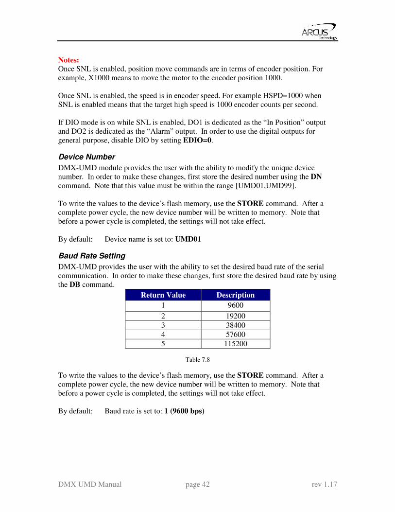
Baud Rate Setting
DMX-UMD provides the user with the ability to set the desired baud rate of the serial
communication. In order to make these changes, first store the desired baud rate by using
the DB command.
Return Value Description
1 9600
2 19200
3 38400
4 57600
5 115200
Table 7.8
To write the values to the device’s flash memory, use the STORE command. After a
complete power cycle, the new device number will be written to memory. Note that
before a power cycle is completed, the settings will not take effect.
By default: Baud rate is set to: 1 (9600 bps)

DMX UMD Manual page 43 rev 1.17
Sync Output
DMX-UMD has a designated synchronization digital output (DO2). The synchronization
signal output is triggered when the encoder position value meets the set condition.
While this feature is enabled, the designated digital output (DO2) cannot be controlled by
user.
Use SYNO to enable the synchronization output feature.
Use SYNF to disable the synchronization output feature.
Use SYNP to read and set the synchronization position value. (28-bit signed number)
Use SYNC to set the synchronization condition.
1 – Turn the output on when the encoder position is EQUAL to sync position.
If the synchronization output is done during motion, the sync output pulse will
turn on only when the encoder position and sync position are equal.
2 – Turns output on when the encoder position is LESS than the sync position.
3 – Turns output on when the encoder position is GREATER than sync position.
Use SYNT to set the pulse width output time (ms). This parameter is only used if the
synchronization condition is set to 1. Note the maximum pulse width is 10 ms. If this
parameter is set to 0, the output pulse will depend on how long the encoder value is equal
to the sync position.
Use SYNS to read the synchronization output status.
0 – Sync output feature is off
1 – Waiting for sync condition
2 – Sync condition occurred
When sync output feature is first enabled, the digital output turns on (i.e. the output is
pulled to GND and DO2=1). Once sync output is triggered, the digital output turns off
(i.e. the output is pulled to Vs and DO2=0).
Broadcasting over RS-485
The address ‘00’ is reserved for broadcasting over an RS-485 bus. Any ASCII command
prefixed by ‘@00’ will be processed by all DMX-UMD modules on the RS-485 bus.
When a broadcast command is received by an DMX-UMD module, no response is sent
back to the master.
Response Type
It is possible to choose between two types of response string formats. This parameter can
be set using the RT command.
Format 1 (default): [Response][CR]
DMX UMD Manual page 44 rev 1.17
Examples:
For querying the encoder position
Send: @01EX[CR]
Reply: 1000[CR]
For jogging the motor in positive direction
Send: @01J+[CR]
Reply: OK[CR]
To achieve this response string type, set RT=0.
Format 2: #[DeviceName][Response][CR]
Examples:
For querying the encoder position
Send: @01EX[CR]
Reply: #011000[CR]
For jogging the motor in positive direction
Send: @01J+[CR]
Reply: #01OK[CR]
To achieve this response string type, set RT=1.
To write the response type parameter to flash memory, use the STORE command. After
a complete power cycle, the new response type will take effect. Note that before a power
cycle is done, the setting will not take effect.
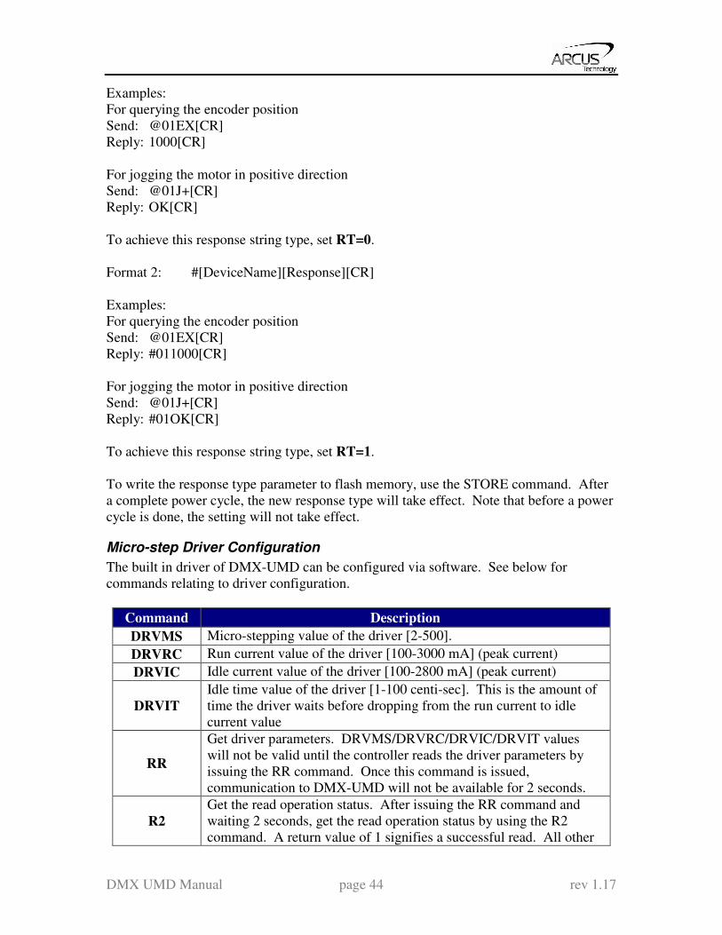
Micro-step Driver Configuration
The built in driver of DMX-UMD can be configured via software. See below for
commands relating to driver configuration.
Command Description
DRVMS Micro-stepping value of the driver [2-500].
DRVRC Run current value of the driver [100-3000 mA] (peak current)
DRVIC Idle current value of the driver [100-2800 mA] (peak current)
DRVIT
Idle time value of the driver [1-100 centi-sec]. This is the amount of
time the driver waits before dropping from the run current to idle
current value
RR
Get driver parameters. DRVMS/DRVRC/DRVIC/DRVIT values
will not be valid until the controller reads the driver parameters by
issuing the RR command. Once this command is issued,
communication to DMX-UMD will not be available for 2 seconds.
R2
Get the read operation status. After issuing the RR command and
waiting 2 seconds, get the read operation status by using the R2
command. A return value of 1 signifies a successful read. All other
DMX UMD Manual page 45 rev 1.17
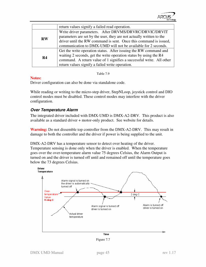
return values signify a failed read operation.
RW
Write driver parameters. After DRVMS/DRVRC/DRVIC/DRVIT
parameters are set by the user, they are not actually written to the
driver until the RW command is sent. Once this command is issued,
communication to DMX-UMD will not be available for 2 seconds.
R4
Get the write operation status. After issuing the RW command and
waiting 2 seconds, get the write operation status by using the R4
command. A return value of 1 signifies a successful write. All other
return values signify a failed write operation.
Table 7.9
Notes: Driver configuration can also be done via standalone code.
While reading or writing to the micro-step driver, StepNLoop, joystick control and DIO
control modes must be disabled. These control modes may interfere with the driver
configuration.
Over Temperature Alarm
The integrated driver included with DMX-UMD is DMX-A2-DRV. This product is also
available as a standard driver + motor-only product. See website for details.
Warning: Do not dissemble top controller from the DMX-A2-DRV. This may result in
damage to both the controller and the driver if power is being supplied to the unit.
DMX-A2-DRV has a temperature sensor to detect over heating of the driver.
Temperature sensing is done only when the driver is enabled. When the temperature
goes over the over-temperature alarm value 75 degrees Celsius, the Alarm Output is
turned on and the driver is turned off until and remained off until the temperature goes
below the 73 degrees Celsius.
Figure 7.7
DMX UMD Manual page 46 rev 1.17
Standalone Programming
Standalone Program Specification:
Memory size: 1785 assembly lines ~ 10.5 KB.
Note: Each line of pre-compiled code equates to 1-4 lines of assembly lines.
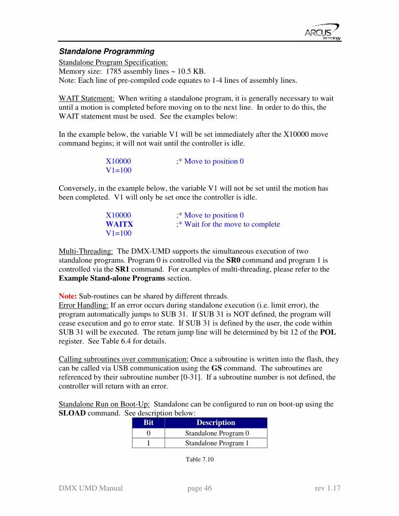
WAIT Statement: When writing a standalone program, it is generally necessary to wait
until a motion is completed before moving on to the next line. In order to do this, the
WAIT statement must be used. See the examples below:
In the example below, the variable V1 will be set immediately after the X10000 move
command begins; it will not wait until the controller is idle.
X10000 ;* Move to position 0
V1=100
Conversely, in the example below, the variable V1 will not be set until the motion has
been completed. V1 will only be set once the controller is idle.
X10000 ;* Move to position 0
WAITX ;* Wait for the move to complete
V1=100
Multi-Threading: The DMX-UMD supports the simultaneous execution of two
standalone programs. Program 0 is controlled via the SR0 command and program 1 is
controlled via the SR1 command. For examples of multi-threading, please refer to the
Example Stand-alone Programs section.
Note: Sub-routines can be shared by different threads.
Error Handling: If an error occurs during standalone execution (i.e. limit error), the
program automatically jumps to SUB 31. If SUB 31 is NOT defined, the program will
cease execution and go to error state. If SUB 31 is defined by the user, the code within
SUB 31 will be executed. The return jump line will be determined by bit 12 of the POL
register. See Table 6.4 for details.
Calling subroutines over communication: Once a subroutine is written into the flash, they
can be called via USB communication using the GS command. The subroutines are
referenced by their subroutine number [0-31]. If a subroutine number is not defined, the
controller will return with an error.
Standalone Run on Boot-Up: Standalone can be configured to run on boot-up using the
SLOAD command. See description below:
Bit Description
0 Standalone Program 0
1 Standalone Program 1
Table 7.10
DMX UMD Manual page 47 rev 1.17
Note: DIO communication is not allowed while a standalone programming is running.
If DIO communication is enabled while a standalone program begins execution, DIO
communication will be automatically disabled.
Communication Time-out Feature (Watchdog)
DMX-UMD allows for the user to trigger an alarm if the master has not communicated
with the device for a set period of time. When an alarm is triggered, bit 10 of the MST
parameter is turned on. The time-out value is set by the TOC command. Units are in
milliseconds. This feature is usually used in stand-alone mode. Refer to the Example
Stand-alone Programs section for an example.
In order to disable this feature set TOC=0.
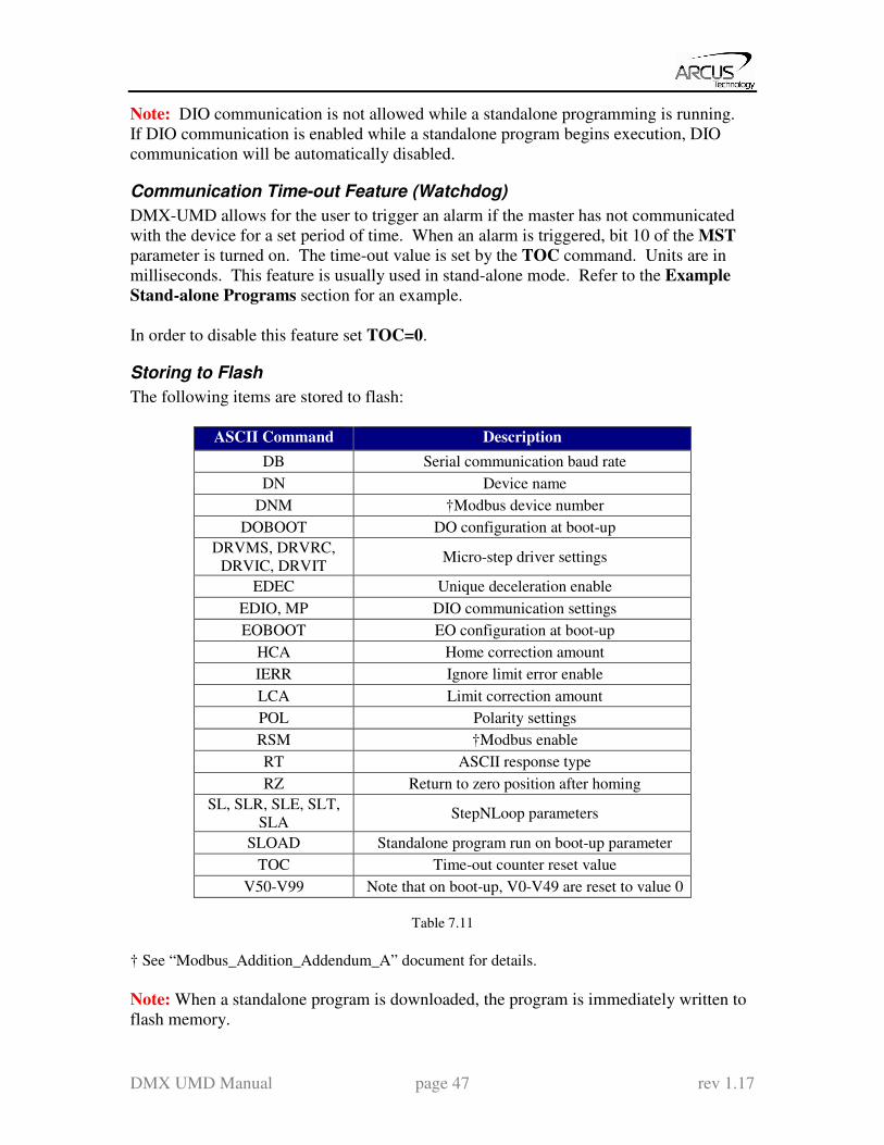
Storing to Flash
The following items are stored to flash:
ASCII Command Description
DB Serial communication baud rate
DN Device name
DNM †Modbus device number
DOBOOT DO configuration at boot-up
DRVMS, DRVRC,
DRVIC, DRVIT Micro-step driver settings
EDEC Unique deceleration enable
EDIO, MP DIO communication settings
EOBOOT EO configuration at boot-up
HCA Home correction amount
IERR Ignore limit error enable
LCA Limit correction amount
POL Polarity settings
RSM †Modbus enable
RT ASCII response type
RZ Return to zero position after homing
SL, SLR, SLE, SLT,
SLA StepNLoop parameters
SLOAD Standalone program run on boot-up parameter
TOC Time-out counter reset value
V50-V99 Note that on boot-up, V0-V49 are reset to value 0
Table 7.11
† See “Modbus_Addition_Addendum_A” document for details.
Note: When a standalone program is downloaded, the program is immediately written to
flash memory.
DMX UMD Manual page 48 rev 1.17
8. Communication – USB
DMX-UMD USB communication is USB 2.0 compliant.
Communication between the PC and DMX-UMD is done using Windows compatible
DLL API function calls as shown below. Windows programming language such as
Visual BASIC, Visual C++, LABView, or any other programming language that can use
DLL can be used to communicate with the Performax module.
Typical communication transaction time between PC and DMX-UMD for sending a
command from a PC and getting a reply from DMX-UMD using the
fnPerformaxComSendRecv() API function is in single digit milliseconds. This value
will vary with CPU speed of PC and the type of command.
USB Communication API Functions
For USB communication, following DLL API functions are provided.
BOOL fnPerformaxComGetNumDevices(OUT LPDWORD lpNumDevices);
- This function is used to get total number of all types of Performax and
Performax USB modules connected to the PC.
BOOL fnPerformaxComGetProductString(IN DWORD dwNumDevices,
OUT LPVOID lpDeviceString,
IN DWORD dwOptions);
- This function is used to get the Performax or Performax product string. This
function is used to find out Performax USB module product string and its
associated index number. Index number starts from 0.
BOOL fnPerformaxComOpen(IN DWORD dwDeviceNum,
OUT HANDLE* pHandle);
- This function is used to open communication with the Performax USB module
and to get communication handle. dwDeviceNum starts from 0.
BOOL fnPerformaxComClose(IN HANDLE pHandle);
- This function is used to close communication with the Performax USB
module.
BOOL fnPerformaxComSetTimeouts(IN DWORD dwReadTimeout,
DWORD dwWriteTimeout);
- This function is used to set the communication read and write timeout. Values
are in milliseconds. This must be set for the communication to work. Typical
value of 1000 msec is recommended.
BOOL fnPerformaxComSendRecv(IN HANDLE pHandle,
IN LPVOID wBuffer,

DMX UMD Manual page 49 rev 1.17
IN DWORD dwNumBytesToWrite,
IN DWORD dwNumBytesToRead,
OUT LPVOID rBuffer);
- This function is used to send command and get reply. Number of bytes to
read and write must be 64 characters.
BOOL fnPerformaxComFlush(IN HANDLE pHandle)
- Flushes the communication buffer on the PC as well as the USB controller. It
is recommended to perform this operation right after the communication
handle is opened.
USB Communication Issues
A common problem that users may have with USB communication is that after sending a
command from the PC to the device, the response is not received by the PC until another
command is sent. In this case, the data buffers between the PC and the USB device are
out of sync. Below are some suggestions to help alleviate this issue.
1) Buffer Flushing: If USB communication begins from an unstable state (i.e. your
application has closed unexpectedly, it is recommended to first flush the USB
buffers of the PC and the USB device. See the following function prototype
below:
BOOL fnPerformaxComFlush(IN HANDLE pHandle)
Note: fnPerformaxComFlush is only available in the most recent
PerformaxCom.dll which is not registered by the standard USB driver installer. A
sample of how to use this function along with this newest DLL is available for
download on the website
2) USB Cable: Another source of USB communication issues may come from the
USB cable. Confirm that the USB cable being used has a noise suppression
choke. See photo below:
Figure 8.0
DMX UMD Manual page 50 rev 1.17
9. Communication – RS-485 (ASCII)
When communicating on RS-485 (ASCII), it is recommended to add 120 Ohm
terminating resistor between 485+ and 485- signal on the last module.
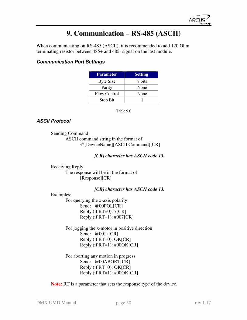
Communication Port Settings
Parameter Setting
Byte Size 8 bits
Parity None
Flow Control None
Stop Bit 1
Table 9.0
ASCII Protocol
Sending Command
ASCII command string in the format of
@[DeviceName][ASCII Command][CR]
[CR] character has ASCII code 13.
Receiving Reply
The response will be in the format of
[Response][CR]
[CR] character has ASCII code 13. Examples:
For querying the x-axis polarity
Send: @00POL[CR]
Reply (if RT=0): 7[CR]
Reply (if RT=1): #007[CR]
For jogging the x-motor in positive direction
Send: @00J+[CR]
Reply (if RT=0): OK[CR]
Reply (if RT=1): #00OK[CR]
For aborting any motion in progress
Send: @00ABORT[CR]
Reply (if RT=0): OK[CR]
Reply (if RT=1): #00OK[CR]
Note: RT is a parameter that sets the response type of the device.
DMX UMD Manual page 51 rev 1.17
10. Communication - DIO
DIO communication allows the user to store 16 different types (see Table 10.1) of moves
into DMX-UMD flash memory. These moves can be referenced using the select bits
(DI3-DI6) and triggered by using the start bit (DI1). Motion can be aborted by
triggering the abort/clear bit (DI2). If an error occurs, it can also be cleared by
triggering the abort/clear bit (DI2).
DIO Latency
Digital input response time to a trigger from start bit (DI1) is about 10 micro seconds.
The actual amount of time from trigger to the beginning of the motion move depends on
the command.
Setting Up DIO Parameters
In order to use this feature, you must first enable DIO mode (using EDIO command) as
well as configure the appropriate DIO parameters via USB.
The DIO parameters are set using the MP[X][Y] command.
To view parameters, use command MP[X][Y]. To set values, use MPXY=[value].
X Parameter: This parameter corresponds to the 2
4=16 selections that can be selected by DI3-DI6. This
character must be written in hexadecimal (i.e. 0-F).
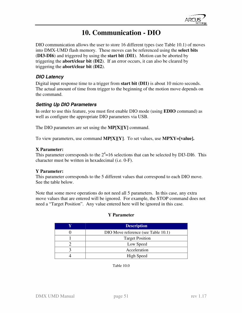
Y Parameter: This parameter corresponds to the 5 different values that correspond to each DIO move.
See the table below.
Note that some move operations do not need all 5 parameters. In this case, any extra
move values that are entered will be ignored. For example, the STOP command does not
need a “Target Position”. Any value entered here will be ignored in this case.
Y Parameter
Y Description
0 DIO Move reference (see Table 10.1)
1 Target Position
2 Low Speed
3 Acceleration
4 High Speed
Table 10.0

DMX UMD Manual page 52 rev 1.17
DIO Move List
Move
Reference Command
0 None
1 STOP
2 X[Target Position]
3 INC+ [Current Position + Target Position]
4 INC- [Current Position - Target Position]
5 J+
6 J-
7 H+
8 H-
9 EO=0
10 EO=1
11 ZH+
12 ZH-
13 SSPD[High Speed]
14 SCV=1
15 SCV=0
16 SL=1
17 SL=0
18 PX=[Target Position]
19 EX=[Target Position]
20 Z+
21 Z-
22 SSPDM=[High Speed]
Table 10.1
Examples
1. Make DIO selection “0” correspond to the J+ command with the following
parameters:
Target Position = NA
Low Speed = 100
Acceleration = 300
High Speed = 1000
Send commands:
MP00 = 5 ` Set move reference for “0” to J+
MP01 = 0 ` Set target position to 0 (value will be ignored)
MP02 = 100 ` Set low speed to 100
DMX UMD Manual page 53 rev 1.17
MP03 = 300 ` Set acceleration to 300
MP04 = 1000 ` Set high speed to 1000
2. Make DIO selection “0xF” correspond to the X800 command with the
following parameters:
Target Position = 800
Low Speed = 500
Acceleration = 500
High Speed = 5000
Send commands:
MPF0 = 2 ` Set move reference for “F” to X[value]
MPF1 = 800 ` Set target position to 800
MPF2 = 500 ` Set low speed to 500
MPF3 = 500 ` Set acceleration to 500
MPF4 = 5000 ` Set high speed to 5000
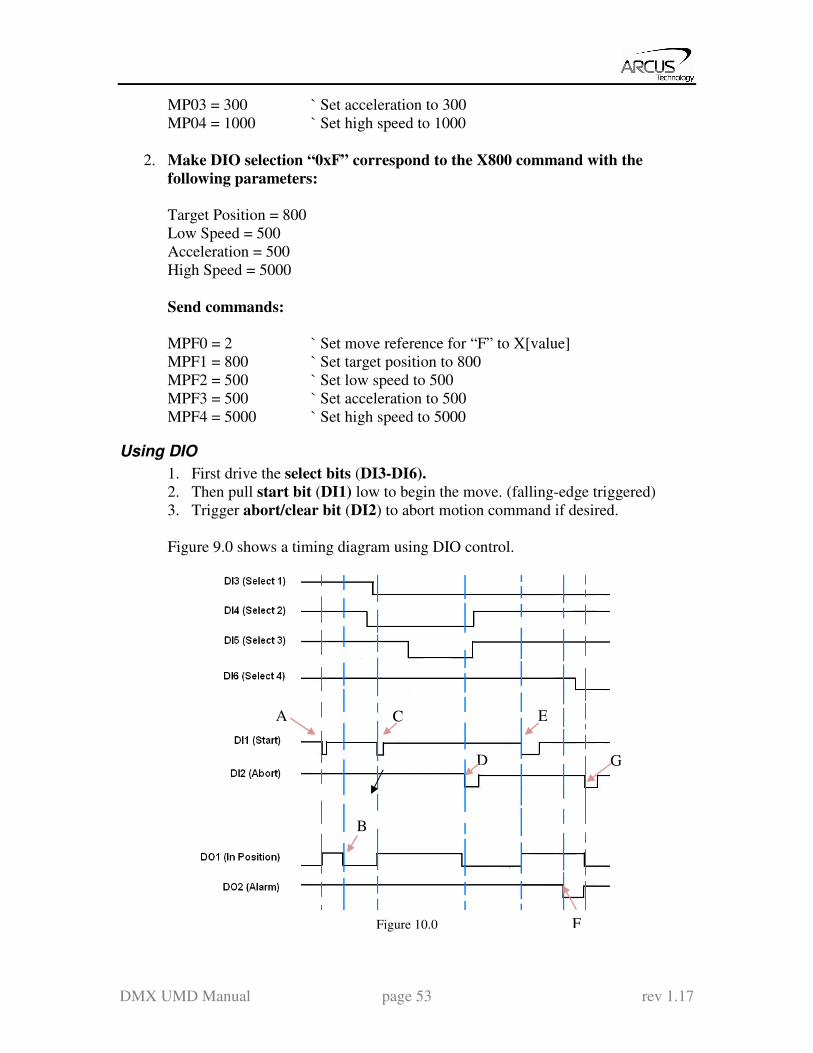
Using DIO
1. First drive the select bits (DI3-DI6).
2. Then pull start bit (DI1) low to begin the move. (falling-edge triggered)
3. Trigger abort/clear bit (DI2) to abort motion command if desired.
Figure 9.0 shows a timing diagram using DIO control.
Figure 10.0
C E
D
F
A
G
B
DMX UMD Manual page 54 rev 1.17
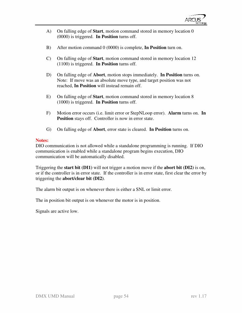
A) On falling edge of Start, motion command stored in memory location 0
(0000) is triggered. In Position turns off.
B) After motion command 0 (0000) is complete, In Position turn on.
C) On falling edge of Start, motion command stored in memory location 12
(1100) is triggered. In Position turns off.
D) On falling edge of Abort, motion stops immediately. In Position turns on.
Note: If move was an absolute move type, and target position was not
reached, In Position will instead remain off.
E) On falling edge of Start, motion command stored in memory location 8
(1000) is triggered. In Position turns off.
F) Motion error occurs (i.e. limit error or StepNLoop error). Alarm turns on. In
Position stays off. Controller is now in error state.
G) On falling edge of Abort, error state is cleared. In Position turns on.
Notes: DIO communication is not allowed while a standalone programming is running. If DIO
communication is enabled while a standalone program begins execution, DIO
communication will be automatically disabled.
Triggering the start bit (DI1) will not trigger a motion move if the abort bit (DI2) is on,
or if the controller is in error state. If the controller is in error state, first clear the error by
triggering the abort/clear bit (DI2).
The alarm bit output is on whenever there is either a SNL or limit error.
The in position bit output is on whenever the motor is in position.
Signals are active low.
DMX UMD Manual page 55 rev 1.17
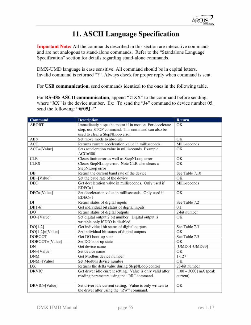
11. ASCII Language Specification
Important Note: All the commands described in this section are interactive commands
and are not analogous to stand-alone commands. Refer to the “Standalone Language
Specification” section for details regarding stand-alone commands.
DMX-UMD language is case sensitive. All command should be in capital letters.
Invalid command is returned “?”. Always check for proper reply when command is sent.
For USB communication, send commands identical to the ones in the following table.
For RS-485 ASCII communication, append “@XX” to the command before sending,
where “XX” is the device number. Ex: To send the “J+” command to device number 05,
send the following: “@05J+”
Command Description Return
ABORT Immediately stops the motor if in motion. For decelerate
stop, use STOP command. This command can also be
used to clear a StepNLoop error
OK
ABS Set move mode to absolute OK
ACC Returns current acceleration value in milliseconds. Milli-seconds
ACC=[Value] Sets acceleration value in milliseconds. Example:
ACC=300
OK
CLR Clears limit error as well as StepNLoop error OK
CLRS Clears StepNLoop error. Note CLR also clears a
StepNLoop error
OK
DB Return the current baud rate of the device See Table 7.10
DB=[Value] Set the baud rate of the device OK
DEC Get deceleration value in milliseconds. Only used if
EDEC=1
Milli-seconds
DEC=[Value] Set deceleration value in milliseconds. Only used if
EDEC=1
OK
DI Return status of digital inputs See Table 7.2
DI[1-6] Get individual bit status of digital inputs 0,1
DO Return status of digital outputs 2-bit number
DO=[Value] Set digital output 2 bit number. Digital output is
writable only if DIO is disabled.
OK
DO[1-2] Get individual bit status of digital outputs See Table 7.3
DO[1-2]=[Value] Set individual bit status of digital outputs OK
DOBOOT Get DO boot-up state See Table 7.3
DOBOOT=[Value] Set DO boot-up state OK
DN Get device name [UMD01-UMD99]
DN=[Value] Set device name OK
DNM Get Modbus device number 1-127
DNM=[Value] Set Modbus device number OK
DX Returns the delta value during StepNLoop control 28-bit number
DRVIC Get driver idle current setting. Value is only valid after
reading parameters using the “RR” command.
[100 – 3000] mA (peak
current)
DRVIC=[Value] Set driver idle current setting. Value is only written to
the driver after using the “RW” command.
OK
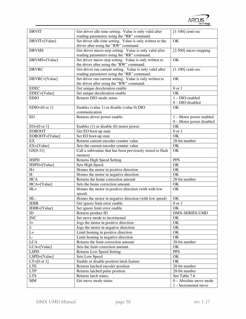
DMX UMD Manual page 56 rev 1.17
DRVIT Get driver idle time setting. Value is only valid after
reading parameters using the “RR” command.
[1-100] centi-sec
DRVIT=[Value] Set driver idle time setting. Value is only written to the
driver after using the “RW” command.
OK
DRVMS Get driver micro-step setting. Value is only valid after
reading parameters using the “RR” command.
[2-500] micro-stepping
DRVMS=[Value] Set driver micro-step setting. Value is only written to
the driver after using the “RW” command.
OK
DRVRC Get driver run current setting. Value is only valid after
reading parameters using the “RR” command.
[1-100] centi-sec
DRVRC=[Value] Set driver run current setting. Value is only written to
the driver after using the “RW” command.
OK
EDEC Get unique deceleration enable 0 or 1
EDEC=[Value] Set unique deceleration enable OK
EDIO Returns DIO mode status 1 – DIO enabled
0 – DIO disabled
EDIO=[0 or 1] Enables (value 1) or disable (value 0) DIO
communication
OK
EO Returns driver power enable. 1 – Motor power enabled
0 – Motor power disabled
EO=[0 or 1] Enables (1) or disable (0) motor power. OK
EOBOOT Get EO boot-up state 0 or 1
EOBOOT=[Value] Set EO boot-up state OK
EX Returns current encoder counter value 28-bit number
EX=[Value] Sets the current encoder counter value OK
GS[0-31] Call a subroutine that has been previously stored to flash
memory
OK
HSPD Returns High Speed Setting PPS
HSPD=[Value] Sets High Speed. OK
H+ Homes the motor in positive direction OK
H- Homes the motor in negative direction OK
HCA Returns the home correction amount 28-bit number
HCA=[Value] Sets the home correction amount. OK
HL+ Homes the motor in positive direction (with with low
speed)
OK
HL- Homes the motor in negative direction (with low speed) OK
IERR Get ignore limit error enable 0 or 1
IERR=[Value] Set ignore limit error enable OK
ID Returns product ID DMX-SERIES-UMD
INC Set move mode to incremental OK
J+ Jogs the motor in positive direction OK
J- Jogs the motor in negative direction OK
L+ Limit homing in positive direction OK
L- Limit homing in negative direction OK
LCA Returns the limit correction amount 28-bit number
LCA=[Value] Sets the limit correction amount. OK
LSPD Returns Low Speed Setting PPS
LSPD=[Value] Sets Low Speed OK
LT=[0 or 1] Enable or disable position latch feature OK
LTE Returns latched encoder position 28-bit number
LTP Returns latched pulse position 28-bit number
LTS Returns latch status. See Table 7.6
MM Get move mode status 0 – Absolute move mode
1 – Incremental move

DMX UMD Manual page 57 rev 1.17
mode
MST Returns motor status See Table 7.5
MPXX Get DIO parameter
MPXX=[Value] Set DIO parameter OK
POL Returns current polarity See Table 7.4
POL=[value] Sets polarity. OK
PS Returns current pulse speed PPS
PX Returns current position value 28-bit number
PX=[value] Sets the current position value OK
R2 Get driver read operation status [1] – Driver read
successful
[2-7] – Driver read failure
R4 Get driver write operation status [1] – Driver write
successful
[2-7] – Driver write
failure
RR Read driver parameters OK
RSM Get Modbus enable 0 or 1
RSM= [0 or 1] Set Modbus enable OK
RT Get response type value 0 or 1
RT= [0 or 1] Set response type value OK
RZ Get return zero enable. Used during homing 0 or 1
RZ=[0 or 1] Set return zero enable. Used during homing OK
RW Write driver parameters OK
SASTAT[0,1] Get standalone program status
0 – Stopped
1 – Running
2 – Paused
4 – In Error
0-4
SA[LineNumber] Get standalone line
LineNumber: [0,1784]
SA[LineNumber]=[Value] Set standalone line
LineNumber: [0,1784]
SCV Returns the s-curve control 0 or 1
SCV=[0 or 1] Enable or disable s-curve. If disabled, trapezoidal
acceleration/ deceleration will be used.
OK
SL Returns StepNLoop enable status 0 – StepNLoop Off
1 – StepNLoop On
SL=[0 or 1] Enable or disable StepNLoop Control OK
SLA Returns maximum number of StepNLoop control
attempt
28-bit number
SLA=[value] Sets maximum number of StepNLoop control attempt OK
SLE Returns StepNLoop correction range value. 28-bit number
SLE=[value] Sets StepNLoop correction range value. OK
SLR Returns StepNLoop ratio value [0.001 – 999.999]
SLR=[factor] Sets StepNLoop ratio value. Must be in the range [0.001
– 999.999]
OK
SLS Returns current status of StepNLoop control See Table 7.8
SLT Returns StepNLoop tolerance value 32-bit
SLT=[value] Sets StepNLoop tolerance value. OK
SLOAD Returns RunOnBoot parameter See Table 7.12
SLOAD=[0 or 1] Set RunOnBoot parameter See Table 7.12
SPC[0,1] Get program counter for standalone program [0-1784]
SR[0,1]=[Value] Control standalone program: OK

DMX UMD Manual page 58 rev 1.17
0 – Stop standalone program
1 – Run standalone program
2 – Pause standalone program
3 – Continue standalone program
SSPD[value] On-the-fly speed change. In order to use this command,
S-curve control must be disabled. Use SCV command to
enable and disable s-curve acceleration/ deceleration
control. Note that an “=” sign is not used for this
command.
OK
SSPDM Return on-the-fly speed change mode [0-9]
SSPDM=[value] Set on-the-fly speed change mode OK
STOP Stops the motor using deceleration if in motion. OK
STORE Store settings to flash OK
SYNC
Read sync output configuration
1 – trigger when encoder equals position
2 – trigger when encoder is LESS than position
3 – trigger when encoder is GREATER than position
1,2,3
SYNC= Set sync output configuration
1 – trigger when encoder equals position
2 – trigger when encoder is LESS than position
3 – trigger when encoder is GREATER than position
OK
SYNF
Turn off sync output OK
SYNO
Turn on sync output OK
SYNP
Get trigger position 28 bit signed number
SYNP=
Set trigger position 28 bit signed number
SYNT
Get pulse width time (ms). Only applicable if sync
output configuration is set to 1.
Milli-seconds
SYNT= Set pulse width time (ms). Only applicable if sync
output configuration is set to 1. Max 30ms
OK
T[value] On-the-fly target change OK
TOC Get time-out counter (ms) 32-bit number
TOC=[value] Set time-out counter (ms) OK
V[0-99] Read variables 0-99 28-bit number
V[0-99]=[value] Set variables 0-99 OK
VER Get firmware version VXXX
X[value] Moves the motor to absolute position value using the
HSPD, LSPD, and ACC values.
OK
Z+ Homes the motor in positive direction using the Z index
encoder channel ONLY.
OK
Z- Homes the motor in negative direction using the Z index
encoder channel ONLY.
OK
ZH+ Homes the motor in positive direction using the home
switch and then Z index encoder channel.
OK
ZH- Homes the motor in negative direction using the home
switch and then Z index encoder channel.
OK
Table 11.0
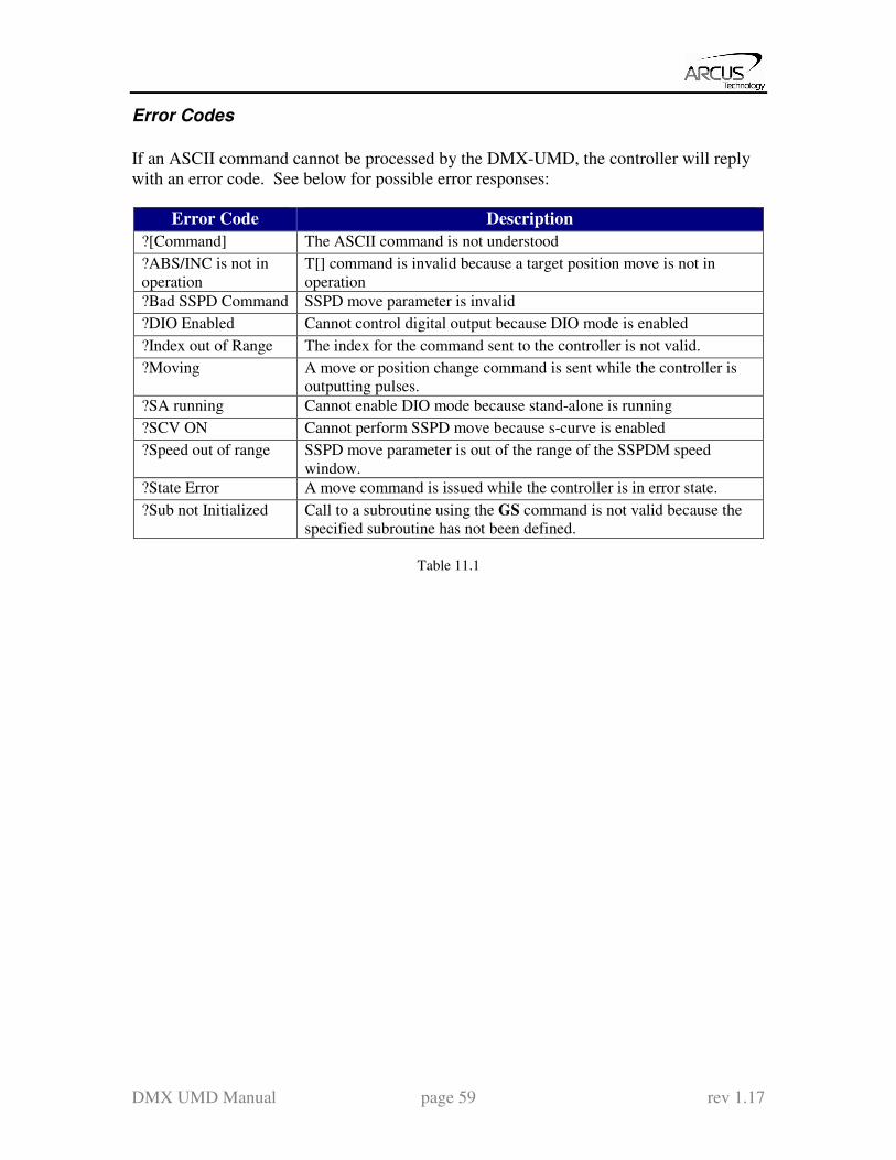
DMX UMD Manual page 59 rev 1.17
Error Codes
If an ASCII command cannot be processed by the DMX-UMD, the controller will reply
with an error code. See below for possible error responses:
Error Code Description
?[Command] The ASCII command is not understood
?ABS/INC is not in
operation
T[] command is invalid because a target position move is not in
operation
?Bad SSPD Command SSPD move parameter is invalid
?DIO Enabled Cannot control digital output because DIO mode is enabled
?Index out of Range The index for the command sent to the controller is not valid.
?Moving A move or position change command is sent while the controller is
outputting pulses.
?SA running Cannot enable DIO mode because stand-alone is running
?SCV ON Cannot perform SSPD move because s-curve is enabled
?Speed out of range SSPD move parameter is out of the range of the SSPDM speed
window.
?State Error A move command is issued while the controller is in error state.
?Sub not Initialized Call to a subroutine using the GS command is not valid because the
specified subroutine has not been defined.
Table 11.1
DMX UMD Manual page 60 rev 1.17
12. Standalone Language Specification
;
Description:
Comment notation. In programming, comment must be in its own line.
Syntax:
; [Comment Text]
Examples:
; ***This is a comment
JOGX+ ;***Jogs axis to positive direction
DELAY=1000 ;***Wait 1 second
ABORT ;***Stop immediately all axes including X axis
ABORTX
Description:
Motion: Immediately stop motion without deceleration.
Syntax:
ABORTX
Examples:
JOGX+ ;***Jogs axis to positive direction
DELAY=1000 ;***Wait 1 second
ABORTX ;***Stop axis immediately
ABS
Description:
Command: Changes all move commands to absolute mode.
Syntax:
ABS
Examples:
ABS ;***Change to absolute mode
PX=0 ;***Change position to 0
X1000 ;***Move X axis to position 1000
WAITX
X3000 ;***Move X axis to position 3000
WAITX
ACC
Description:
Read: Get acceleration value
Write: Set acceleration value.
Value is in milliseconds.
Syntax:
Read: [variable] = ACC
Write: ACC = [value]
ACC = [variable]
DMX UMD Manual page 61 rev 1.17
Examples:
ACC=300 ;***Sets the acceleration to 300 milliseconds
V3=500 ;***Sets the variable 3 to 500
ACC=V3 ;***Sets the acceleration to variable 3 value of 500
DEC
Description:
Read: Get deceleration value
Write: Set deceleration value.
Value is in milliseconds.
Syntax:
Read: [variable] = DEC
Write: DEC = [value]
DEC = [variable]
Examples:
DEC=300 ;***Sets the deceleration to 300 milliseconds
V3=500 ;***Sets the variable 3 to 500
DEC=V3 ;***Sets the deceleration to variable 3 value of 500
DELAY
Description:
Set a delay (1 ms units)
Syntax:
Delay=[Number] (1 ms units)
Examples:
JOGX+ ;***Jogs axis to positive direction
DELAY=10000 ;***Wait 10 second
ABORTX ;***Stop axis
DI
Description:
Read: Gets the digital input value. DMX-UMD has 6 digital inputs.
Digital inputs are active high
Syntax:
Read: [variable] = DI
Conditional: IF DI=[variable]
ENDIF
IF DI=[value]
ENDIF
Examples:
IF DI=0
DO=1 ;***If all digital inputs are triggered, set DO=1
ENDIF

DMX UMD Manual page 62 rev 1.17
DI[1-6]
Description:
Read: Gets the digital input value. DMX-UMD has 6 digital inputs.
If digital input is on (i.e. input is pulled to GND of opto-supply), the bit status is 0.
Otherwise, the bit status is 1.
Syntax:
Read: [variable] = DI[1-6]
Conditional: IF DI[1-6]=[variable]
ENDIF
IF DI[1-6]=[0 or 1]
ENDIF
Examples:
IF DI1=0
DO=1 ;***If digital input 1 is triggered, set DO=1
ENDIF
DO
Description:
Read: Gets the digital output value
Write: Sets the digital output value
DMX-UMD has 2 digital outputs.
Syntax:
Read: [variable] = DO
Write: DO = [value]
DO = [variable]
Conditional: IF DO=[variable]
ENDIF
IF DO=[value]
ENDIF
Examples:
DO=3 ;***Turn on both bits
DO[1-2]
Description:
Read: Gets the individual digital output value
Write: Sets the individual digital output value
DMX-UMD has 2 digital outputs.
Syntax:
Read: [variable] = DO[1-2]
Write: DO[1-2] = [0 or 1]
DO[1-2] = [variable]
Conditional: IF DO[1-2]=[variable]
ENDIF

DMX UMD Manual page 63 rev 1.17
IF DO[1-2]=[0 or 1]
ENDIF
Examples:
DO1=1 ;***Turn DO1 on
DO2=1 ;***Turn DO2 on
DRVIC
Description:
Write: Sets the driver idle current parameter
Syntax:
Write: DRVIC=[value]
Examples:
WHILE 1=1
IF DI1 = 0 ;***If DI1 is triggered, execute
SL=0 ;***Disable StepNLoop
DRVMS=100 ;***Micro-step set to 100
DRVIT=1 :***Idle-time set to 1 cent-sec
DRVIC=100 ;***Idle-current set to 100 mA
DRVRC=1000 ;***Run-current set to 1000 mA
RW ;***Write driver parameters
DELAY=2000 ;***Wait 2 seconds for write operation
V1=RWSTAT ;***Check write operation status
IF V1=1
DO1=1 ;***If write operation was success, DO1=1
ELSE
DO2=1 ;***Write operation failed, DO2=1
ENDIF
ENDIF
ENDWHILE
DRVIT
Description:
Write: Sets the driver idle time parameter
Syntax:
Write: DRVIT=[value]
Examples: See DRVIC
DRVMS
Description:
Write: Sets the driver micro-step parameter
Syntax:
Write: DRVMS=[value]
Examples: See DRVIC
DMX UMD Manual page 64 rev 1.17
DRVRC
Description:
Write: Sets the driver run current parameter
Syntax:
Write: DRVRC=[value]
Examples: See DRVIC
ECLEARX
Description:
Write: Clears motor error status. Also clears a StepNLoop error.
Syntax:
Write: ECLEARX
Examples:
ECLEARX ;***Clears motor error
ECLEARSX
Description:
Write: Clears StepNLoop error status. ECLEAR also clears a StepNLoop error
Syntax:
Write: ECLEARSX
Examples:
ECLEARSX ;***Clears StepNLoop error
ELSE
Description:
Perform ELSE condition check as a part of IF statement
Syntax:
ELSE
Examples:
IF V1=1
X1000 ;***If V1 is 1, then move to 1000
WAITX
ELSE
X-1000 ;***If V1 is not 1, then move to -1000
WAITX
ENDIF
ELSEIF
Description:
Perform ELSEIF condition check as a part of the IF statement
Syntax:
ELSEIF [Argument 1] [Comparison] [Argument 2]
[Argument] can be any of the following:
Numerical value
Pulse or Encoder Position

DMX UMD Manual page 65 rev 1.17
Digital Output
Digital Input
Enable Output
Motor Status
[Comparison] can be any of the following
= Equal to
> Greater than
< Less than
>= Greater than or equal to
<= Less than or equal to
!= Not Equal to
Examples:
IF V1=1
X1000
WAITX
ELSEIF V1=2
X2000
WAITX
ELSEIF V1=3
X3000
WAITX
ELSE
X0
WAITX
ENDIF
END
Description:
Indicate end of program.
Program status changes to idle when END is reached.
Note: Subroutine definitions should be written AFTER the END statement
Syntax:
END
Examples:
X0
WAITX
X1000
WAITX
END
DMX UMD Manual page 66 rev 1.17
ENDIF
Description:
Indicates end of IF operation
Syntax:
ENDIF
Examples:
IF V1=1
X1000
WAITX
ENDIF
ENDSUB
Description:
Indicates end of subroutine
When ENDSUB is reached, the program returns to the previously called
subroutine.
Syntax:
ENDSUB
Examples:
GOSUB 1
END
SUB 1
X0
WAITX
X1000
WAITX
ENDSUB
ENDWHILE
Description:
Indicate end of WHILE loop
Syntax:
ENDWHILE
Examples:
WHILE V1=1 ;***While V1 is 1 continue to loop
X0
WAITX
X1000
WAITX
ENDWHILE ;***End of while loop so go back to WHILE

DMX UMD Manual page 67 rev 1.17
EO
Description:
Read: Gets the enable output value
Write: Sets the enable output value
Syntax:
Read: [variable] = EO
Write: EO = [value]
EO = [variable]
Conditional: IF EO=[variable]
ENDIF
IF EO=[value]
ENDIF
Examples:
EO=1 ;***Energize motor
EX
Description:
Read: Gets the current encoder position
Write: Sets the current encoder position
Syntax:
Read: [variable] = E[axis]
Write: EX = [0 or 1]
EX = [variable]
Conditional: IF EX=[variable]
ENDIF
IF EX=[value]
ENDIF
Examples:
EX=0 ;***Sets the current encoder position to 0
GOSUB
Description:
Perform go to subroutine operation. Subroutine range is from 0 to 31.
Note: Subroutine definitions should be written AFTER the END statement
Syntax:
GOSUB [subroutine number]
[Subroutine Number] range is 0 to 31
Examples:
GOSUB 0
END
SUB 0
X0
WAITX
X1000
WAITX
ENDSUB

DMX UMD Manual page 68 rev 1.17
HLHOMEX[+ or -]
Description:
Command: Perform homing using current high speed, low speed, and
acceleration.
Syntax:
HLHOMEX[+ or -]
Examples:
HLHOMEX+ ;***Homes the motor at low speed in the positive direction
WAITX
HOMEX[+ or -]
Description:
Command: Perform homing using current high speed, low speed, and
acceleration.
Syntax:
HOMEX[+ or -]
Examples:
HOMEX+ ;***Homes axis in positive direction
WAITX
HSPD
Description:
Read: Gets high speed. Value is in pulses/second
Write: Sets high speed. Value is in pulses/second.
Range is from 1 to 6,000,000.
Syntax:
Read: [variable] = HSPD
Write: HSPD = [value]
HSPD = [variable]
Examples:
HSPD=10000 ;***Sets the high speed to 10,000 pulses/sec
V1=2500 ;***Sets the variable 1 to 2,500
HSPD=V1 ;***Sets the high speed to variable 1 value of 2500
IF
Description:
Perform IF condition check
Syntax:
IF [Argument 1] [Comparison] [Argument 2]
[Argument] can be any of the following:
Numerical value
Pulse or Encoder Position
Digital Output
Digital Input
Enable Output
Motor Status
DMX UMD Manual page 69 rev 1.17
[Comparison] can be any of the following
= Equal to
> Greater than
< Less than
>= Greater than or equal to
<= Less than or equal to
!= Not Equal to
Examples:
IF V1=1
X1000
ENDIF
INC
Description:
Command: Changes all move commands to incremental mode.
Syntax:
INC
Examples:
INC ;***Change to incremental mode
PX=0 ;***Change position to 0
X1000 ;***Move axis to position 1000 (0+1000)
WAITX
X2000 ;***Move axis to position 3000 (1000+2000)
WAITX
JOGX[+ or -]
Description:
Command: Perform jogging using current high speed, low speed, and
acceleration.
Syntax:
JOGX[+ or -]
Examples:
JOGX+ ;***Jogs axis in positive direction
STOPX
WAITX
JOGX- ;***Jogs axis in negative direction
STOPX
WAITX
LHOMEX[+ or -]
Description:
Command: Perform homing using current high speed, low speed, and
acceleration.
Syntax:
LHOMEX[+ or -]

DMX UMD Manual page 70 rev 1.17
Examples:
LHOMEX+ ;***Limit homes axis in positive direction
WAITX
LSPD
Description:
Read: Get low speed. Value is in pulses/second.
Write: Set low speed. Value is in pulses/second.
Range is from 1 to 400,000.
Syntax:
Read: [variable]=LSPD
Write: LSPD=[long value]
LSPD=[variable]
Examples:
LSPD=1000 ;***Sets the start low speed to 1,000 pulses/sec
V1=500 ;***Sets the variable 1 to 500
LSPD=V1 ;***Sets the start low speed to variable 1 value of 500
LTX
Description:
Write: Set latch enable
Range is [0,1]
Syntax:
Write: LTX=[0,1]
LTX=[variable]
Examples:
LTX=1 ;***Enable latch
WHILE 1=1
V2=LTSX ;***Get latch status
IF LTSX = 2
V3=LTEX ;***Get latch encoder value if latch is triggered
V4=LTPX ;***Get latch position value if latch is triggered
ENDIF
ENDWHILE
LTEX
Description:
Read: Get latch encoder value
Syntax:
Read: [variable]=LTEX
Examples:
See LTX
DMX UMD Manual page 71 rev 1.17
LTPX
Description:
Read: Get latch position value
Syntax:
Read: [variable]=LTPX
Examples:
See LTX
LTSX
Description:
Read: Get latch status
Syntax:
Read: [variable]=LTSX
Examples:
See LTX
MSTX
Description:
Read: Get motor status
Syntax:
Read: [variable]=MSTX
Conditional: IF MSTX=[variable]
ENDIF
IF MSTX=[value]
ENDIF
Examples:
IF MSTX=0
DO=3
ELSE
DO=0
ENDIF
PX
Description:
Read: Gets the current pulse position
Write: Sets the current pulse position
Syntax:
Read: Variable = PX
Write: PX = [value]
PX = [variable]
Conditional: IF PX=[variable]
ENDIF
IF PX=[value]
ENDIF

DMX UMD Manual page 72 rev 1.17
Examples:
JOGX+ ;***Jogs axis to positive direction
DELAY=1000 ;***Wait 1 second
ABORTX ;***Stop with deceleration all axes including X axis
PX=0 ;***Sets the current pulse position to 0
PS
Description:
Read: Get the current pulse speed
Syntax:
Read: Variable = PS
Conditional: IF PS=[variable]
ENDIF
IF PS=[value]
ENDIF
Examples:
JOGX+ ;***Jogs axis to positive direction
DELAY=1000 ;***Wait 1 second
ABORTX ;***Stop without deceleration
V1=PS ;***Sets variable 1 to pulse speed
RW
Description:
Write: Start driver write operation. Note that after executing RW, wait 2 seconds
before any other operation is executing (using DELAY=2000).
Syntax:
Write: RW
Examples:
See DRVIC
RWSTAT
Description:
Read: Get driver write operation status
Syntax:
Read: [variable]=RWSTAT
Examples:
See DRVIC
SCVX
Description:
Write: Set s-curve enable.
Range is from 0 or 1
Syntax:
Write: SCVX=[0 or 1]
SCVX=[variable]

DMX UMD Manual page 73 rev 1.17
Note: If s-curve is enabled for an axis, on-the-fly speed feature can not be used for the
corresponding axis.
Examples:
SCVX=1 ;***Sets axis to use s-curve acceleration: on-the-fly speed
; change is NOT allowed for this axis.
SLX
Description:
Write: Set StepNLoop closed-loop mode
Range is from 0 or 1
Syntax:
Write: SL=[0 or 1]
Examples:
SL=1 ;***Sets axis to closed-loop mode
SLSX
Description:
Read: Get StepNLoop status
Syntax:
Read: [variable]=SLSX
Conditional: IF SLSX =[variable]
ENDIF
IF SLSX =[value]
ENDIF
Examples:
IF SLSX != 0
ECLEARX
ELSE
ECLEARSX
ENDIF
SSPDX
Description:
Write: Set on-the-fly speed change for an individual axis.
Range is from 1 to 6,000,000 PPS
Syntax:
Write: SSPDX=[value]
SSPDX=[variable]
Note: If s-curve is enabled for an axis, on-the-fly speed feature cannot be used for the
corresponding axis.
Examples:
SCVX=0 ;***Disable s-curve acceleration
HSPD=1000 ;***X-axis high speed
LSPD=100 ;***Set low speed
ACC=100 ;***Set acceleration
JOGX+ ;***Jogs to positive direction

DMX UMD Manual page 74 rev 1.17
DELAY=1000 ;***Wait 1 second
SSPDX=3000 ;***Change speed on-the-fly to 3000 PPS
SSPDMX
Description:
Write: Set individual on-the-fly speed change mode
Range is from 0 to 9
Syntax:
Write: SSPDMX=[0-9]
SSPDMX=[variable]
Examples:
SCVX=0 ;***Disable s-curve acceleration
HSPD=1000 ;***X-axis high speed
LSPD=100 ;***Set low speed
ACC=100 ;***Set acceleration
JOGX+ ;***Jogs to positive direction
DELAY=1000 ;***Wait 1 second
SSPDMX=1 ;***Set on-the-fly speed change mode to 1
ACC=20000 ;***Set acceleration to 20 seconds
SSPDX=190000 ;***Change speed on-the-fly to 190000 PPS
STOPX
Description:
Command: Stop all axes if in motion with deceleration.
Previous acceleration value is used for deceleration.
Syntax:
STOPX
Examples:
JOGX+ ;***Jogs axis to positive direction
DELAY=1000 ;***Wait 1 second
STOPX ;***Stop with deceleration
STORE
Description:
Command: Store all values to flash
Syntax:
STORE
Examples:
V80=EX ;***Put encoder value in V80
DELAY=1000 ;***Wait 1 second
STORE ;***Store V80 to non-volatile flash

DMX UMD Manual page 75 rev 1.17
SYNCFGX
Description:
Write: Set sync output configuration
Syntax:
Write: SYNCFGX=[value]
SYNCFGX =[variable]
Examples:
SYNCFGX =1 ;*** Set sync output configuration to 1
SYNPOSX=3000 ;*** Set sync output position to 3000
SYNTIMEX=10 ;*** Set sync output pulse time to 10 ms
SYNONX ;*** Turn on sync output feature
V1=1 ;*** Wait until sync output is triggered
WHILE V1 != 2
V1=SYNSTATX
ENDWHILE
SYNOFFX ;*** Disable sync output feature
SYNOFFX
Description:
Write: Disable sync output feature
Syntax:
Write: SYNOFFX
Examples:
See SYNCFGX
SYNONX
Description:
Write: Enable sync output feature
Syntax:
Write: SYNONX
Examples:
See SYNCFGX
SYNPOSX
Description:
Write: Set sync output position.
Syntax:
Write: SYNPOSX=[value]
Write: SYNPOSX=[variable]
Examples:
See SYNCFGX
DMX UMD Manual page 76 rev 1.17
SYNSTATX
Description:
Read: Get status for sync output
Syntax:
Read: [variable] = SYNS
Examples:
See SYNCFGX
SYNTIMEX
Description:
Write: Set pulse output width time for sync output
Syntax:
Write: SYN[axis]T=[value]
Examples:
See SYNCFGX
SUB
Description:
Indicates start of subroutine
Syntax:
SUB [subroutine number]
[Subroutine Number] range is 0 to 31
Examples:
GOSUB 1
END
SUB 1
X0
WAITX
X1000
WAITX
ENDSUB

DMX UMD Manual page 77 rev 1.17
V[0-99]
Description:
Assign to variable.
DMX-UMD has 100 variables [V0-V99]
Syntax:
V[Variable Number] = [Argument]
V[Variable Number] = [Argument1][Operation][Argument2]
Special case for BIT NOT:
V[Variable Number] = ~[Argument]
[Argument] can be any of the following:
Numerical value
Pulse or Encoder Position
Digital Output
Digital Input
Enable Output
Motor Status
[Operation] can be any of the following
+ Addition
- Subtraction
* Multiplication
/ Division
% Modulus
>> Bit Shift Right
<< Bit Shift Left
& Bit AND
| Bit OR
~ Bit NOT
Examples:
V1=12345 ;***Set Variable 1 to 123
V2=V1+1 ;***Set Variable 2 to V1 plus 1
V3=DI ;***Set Variable 3 to digital input value
V4=DO ;***Sets Variable 4 to digital output value
V5=~EO ;***Sets Variable 5 to bit NOT of enable output value
WAITX
Description:
Command: Tell program to wait until move on the certain axis is finished before
executing next line.
Syntax:
WAITX
Examples:
X10000 ;***Move axis to position 10000
WAITX ;***Wait until axis move is done
DO=3 ;***Set digital output
X3000 ;***Move axis to 3000
WAITX ;***Wait until axis move is done
DMX UMD Manual page 78 rev 1.17
WHILE
Description:
Perform WHILE loop
Syntax:
WHILE [Argument 1] [Comparison] [Argument 2]
[Argument] can be any of the following:
Numerical value
Pulse or Encoder Position
Digital Output
Digital Input
Enable Output
Motor Status
[Comparison] can be any of the following
= Equal to
> Greater than
< Less than
>= Greater than or equal to
<= Less than or equal to
!= Not Equal to
Examples:
WHILE V1=1 ;***While V1 is 1 continue to loop
X0
WAITX
X1000
WAITX
ENDWHILE
X
Description:
Command: Perform X axis move to target location
With other Axis moves in the same line, linear interpolation move is done.
Syntax:
X[value]
X[variable]
Examples:
ABS ;***Absolute move mode
X10000 ;***Move to position 10000
WAITX
V10 = 1200 ;***Set variable 10 value to 1200
XV10 ;***Move axis to variable 10 value
WAITX

DMX UMD Manual page 79 rev 1.17
ZHOMEX[+ or -]
Description:
Command: Perform Z-homing using current high speed, low speed, and
acceleration.
Syntax:
ZHOMEX[+ or -]
Examples:
ZHOMEX+ ;***Z Homes axis in positive direction
WAITX
ZHOMEX- ;***Z Homes axis in negative direction
WAITX
ZOMEX[+ or -]
Description:
Command: Perform Zoming (homing only using Z-index) using current high
speed, low speed, and acceleration.
Syntax:
ZOMEX[+ or -]
Examples:
ZOMEX+ ;***Zomes axis in positive direction
WAITX
ZOMEX- ;***Zomes axis in negative direction
WAITX
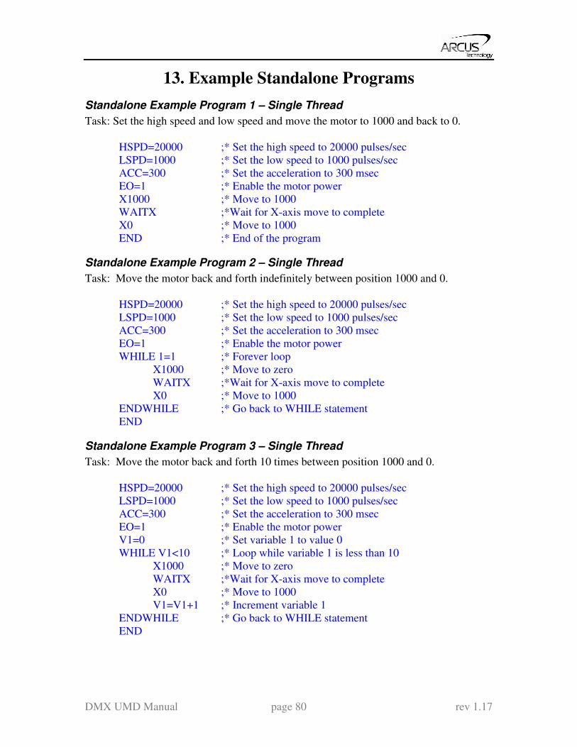
DMX UMD Manual page 80 rev 1.17
13. Example Standalone Programs
Standalone Example Program 1 – Single Thread
Task: Set the high speed and low speed and move the motor to 1000 and back to 0.
HSPD=20000 ;* Set the high speed to 20000 pulses/sec
LSPD=1000 ;* Set the low speed to 1000 pulses/sec
ACC=300 ;* Set the acceleration to 300 msec
EO=1 ;* Enable the motor power
X1000 ;* Move to 1000
WAITX ;*Wait for X-axis move to complete
X0 ;* Move to 1000
END ;* End of the program
Standalone Example Program 2 – Single Thread
Task: Move the motor back and forth indefinitely between position 1000 and 0.
HSPD=20000 ;* Set the high speed to 20000 pulses/sec
LSPD=1000 ;* Set the low speed to 1000 pulses/sec
ACC=300 ;* Set the acceleration to 300 msec
EO=1 ;* Enable the motor power
WHILE 1=1 ;* Forever loop
X1000 ;* Move to zero
WAITX ;*Wait for X-axis move to complete
X0 ;* Move to 1000
ENDWHILE ;* Go back to WHILE statement
END
Standalone Example Program 3 – Single Thread
Task: Move the motor back and forth 10 times between position 1000 and 0.
HSPD=20000 ;* Set the high speed to 20000 pulses/sec
LSPD=1000 ;* Set the low speed to 1000 pulses/sec
ACC=300 ;* Set the acceleration to 300 msec
EO=1 ;* Enable the motor power
V1=0 ;* Set variable 1 to value 0
WHILE V1<10 ;* Loop while variable 1 is less than 10
X1000 ;* Move to zero
WAITX ;*Wait for X-axis move to complete
X0 ;* Move to 1000
V1=V1+1 ;* Increment variable 1
ENDWHILE ;* Go back to WHILE statement
END
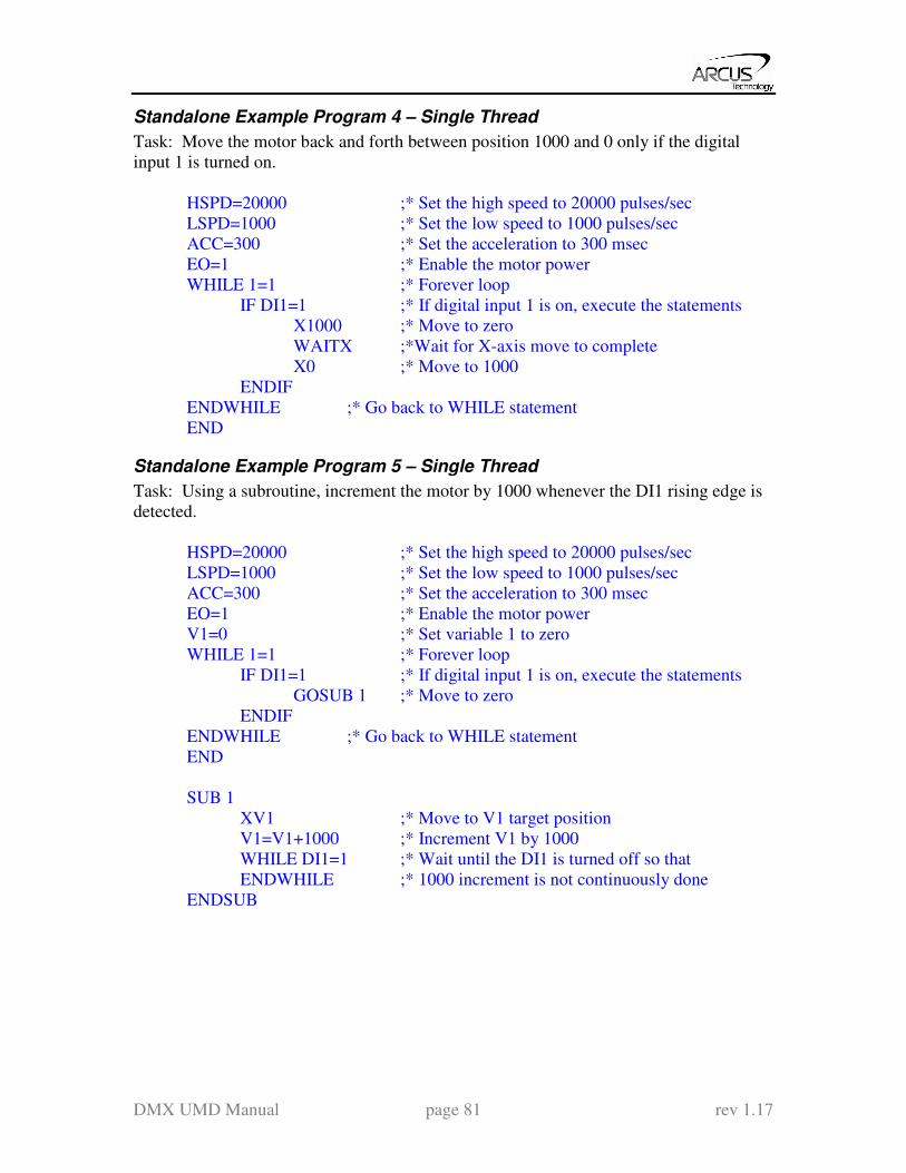
DMX UMD Manual page 81 rev 1.17
Standalone Example Program 4 – Single Thread
Task: Move the motor back and forth between position 1000 and 0 only if the digital
input 1 is turned on.
HSPD=20000 ;* Set the high speed to 20000 pulses/sec
LSPD=1000 ;* Set the low speed to 1000 pulses/sec
ACC=300 ;* Set the acceleration to 300 msec
EO=1 ;* Enable the motor power
WHILE 1=1 ;* Forever loop
IF DI1=1 ;* If digital input 1 is on, execute the statements
X1000 ;* Move to zero
WAITX ;*Wait for X-axis move to complete
X0 ;* Move to 1000
ENDIF
ENDWHILE ;* Go back to WHILE statement
END
Standalone Example Program 5 – Single Thread
Task: Using a subroutine, increment the motor by 1000 whenever the DI1 rising edge is
detected.
HSPD=20000 ;* Set the high speed to 20000 pulses/sec
LSPD=1000 ;* Set the low speed to 1000 pulses/sec
ACC=300 ;* Set the acceleration to 300 msec
EO=1 ;* Enable the motor power
V1=0 ;* Set variable 1 to zero
WHILE 1=1 ;* Forever loop
IF DI1=1 ;* If digital input 1 is on, execute the statements
GOSUB 1 ;* Move to zero
ENDIF
ENDWHILE ;* Go back to WHILE statement
END
SUB 1
XV1 ;* Move to V1 target position
V1=V1+1000 ;* Increment V1 by 1000
WHILE DI1=1 ;* Wait until the DI1 is turned off so that
ENDWHILE ;* 1000 increment is not continuously done
ENDSUB

DMX UMD Manual page 82 rev 1.17
Standalone Example Program 6 – Single Thread
Task: If digital input 1 is on, move to position 1000. If digital input 2 is on, move to
position 2000. If digital input 3 is on, move to 3000. If digital input 5 is on, home the
motor in negative direction. Use digital output 1 to indicate that the motor is moving or
not moving.
HSPD=20000 ;* Set the high speed to 20000 pulses/sec
LSPD=1000 ;* Set the low speed to 1000 pulses/sec
ACC=300 ;* Set the acceleration to 300 msec
EO=1 ;* Enable the motor power
WHILE 1=1 ;* Forever loop
IF DI1=1 ;* If digital input 1 is on
X1000 ;* Move to 1000
ELSEIF DI2=1 ;* If digital input 2 is on
X2000 ;* Move to 2000
ELSEIF DI3=1 ;* If digital input 3 is on
X3000 ;* Move to 3000
ELSEIF DI5=1 ;* If digital input 5 is on
HOMEX- ;* Home the motor in negative direction
ENDIF
V1=MSTX ;* Store the motor status to variable 1
V2=V1&7 ;* Get first 3 bits
IF V2!=0
DO1=1
ELSE
DO1=0
ENDIF
ENDWHILE ;* Go back to WHILE statement
END
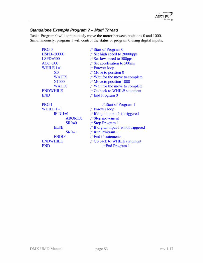
DMX UMD Manual page 83 rev 1.17
Standalone Example Program 7 – Multi Thread
Task: Program 0 will continuously move the motor between positions 0 and 1000.
Simultaneously, program 1 will control the status of program 0 using digital inputs.
PRG 0 ;* Start of Program 0
HSPD=20000 ;* Set high speed to 20000pps
LSPD=500 ;* Set low speed to 500pps
ACC=500 ;* Set acceleration to 500ms
WHILE 1=1 ;* Forever loop
X0 ;* Move to position 0
WAITX ;* Wait for the move to complete
X1000 ;* Move to position 1000
WAITX ;* Wait for the move to complete
ENDWHILE ;* Go back to WHILE statement
END ;* End Program 0
PRG 1 ;* Start of Program 1
WHILE 1=1 ;* Forever loop
IF DI1=1 ;* If digital input 1 is triggered
ABORTX ;* Stop movement
SR0=0 ;* Stop Program 1
ELSE ;* If digital input 1 is not triggered
SR0=1 ;* Run Program 1
ENDIF ;* End if statements
ENDWHILE ;* Go back to WHILE statement
END ;* End Program 1

DMX UMD Manual page 84 rev 1.17
Standalone Example Program 8 – Multi Thread
Task: Program 0 will continuously move the motor between positions 0 and 1000.
Simultaneously, program 1 will monitor the communication time-out parameter and
triggers digital output 1 if a time-out occurs. Program 1 will also stop all motion, disable
program 0 and then re-enable it after a delay of 3 seconds when the error occurs.
PRG 0 ;* Start of Program 0
HSPD=1000 ;* Set high speed to 1000 pps
LSPD=500 ;* Set low speed to 500pps
ACC=500 ;* Set acceleration to 500ms
TOC=5000 ;* Set time-out counter alarm to 5 seconds
EO=1 ;* Enable motor
WHILE 1=1 ;* Forever loop
X0 ;* Move to position 0
WAITX ;* Wait for the move to complete
X1000 ;* Move to position 1000
WAITX ;* Wait for the move to complete
ENDWHILE ;* Go back to WHILE statement
END ;* End Program 0
PRG 1 ;* Start of Program 1
WHILE 1=1 ;* Forever loop
V1=MSTX&1024 ;* Get bit time-out counter alarm variable
IF V1 = 1024 ;* If time-out counter alarm is on
SR0=0 ;* Stop program 0
ABORTX ;* Abort the motor
DO=0 ;* Set DO=0
DELAY=3000;* Delay 3 seconds
SR0=1 ;* Turn program 0 back on
DO=1 ;* Set DO=1
ENDIF
ENDWHILE ;* Go back to WHILE statement
END ;* End Program 1
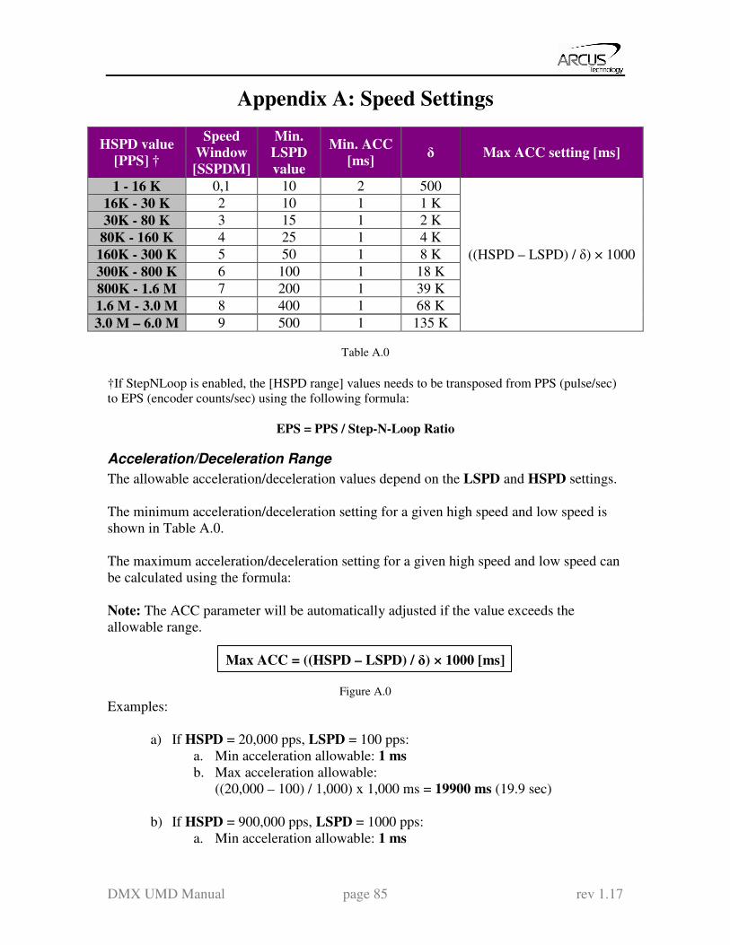
DMX UMD Manual page 85 rev 1.17
Appendix A: Speed Settings
HSPD value
[PPS] †
Speed
Window
[SSPDM]
Min.
LSPD
value
Min. ACC
[ms] δ Max ACC setting [ms]
1 - 16 K 0,1 10 2 500
((HSPD – LSPD) / δ) × 1000
16K - 30 K 2 10 1 1 K
30K - 80 K 3 15 1 2 K
80K - 160 K 4 25 1 4 K
160K - 300 K 5 50 1 8 K
300K - 800 K 6 100 1 18 K
800K - 1.6 M 7 200 1 39 K
1.6 M - 3.0 M 8 400 1 68 K
3.0 M – 6.0 M 9 500 1 135 K
Table A.0
†If StepNLoop is enabled, the [HSPD range] values needs to be transposed from PPS (pulse/sec)
to EPS (encoder counts/sec) using the following formula:
EPS = PPS / Step-N-Loop Ratio
Acceleration/Deceleration Range
The allowable acceleration/deceleration values depend on the LSPD and HSPD settings.
The minimum acceleration/deceleration setting for a given high speed and low speed is
shown in Table A.0.
The maximum acceleration/deceleration setting for a given high speed and low speed can
be calculated using the formula:
Note: The ACC parameter will be automatically adjusted if the value exceeds the
allowable range.
Max ACC = ((HSPD – LSPD) / δ) × 1000 [ms]
Figure A.0
Examples:
a) If HSPD = 20,000 pps, LSPD = 100 pps:
a. Min acceleration allowable: 1 ms
b. Max acceleration allowable:
((20,000 – 100) / 1,000) x 1,000 ms = 19900 ms (19.9 sec)
b) If HSPD = 900,000 pps, LSPD = 1000 pps:
a. Min acceleration allowable: 1 ms

DMX UMD Manual page 86 rev 1.17
b. Max acceleration allowable:
((900,000 – 1000) / 39,000) x 1000 ms = 23050 ms (23.05 sec)
Acceleration/Deceleration Range – Positional Move
When dealing with positional moves, the controller automatically calculates the
appropriate acceleration and deceleration based on the following rules.
Figure A.1
1) ACC vs. DEC 1: If the theoretical position where the controller begins
deceleration is less than L/2, the acceleration value is used for both ramp up and
ramp down. This is regardless of the EDEC setting.
2) ACC vs. DEC 2: If the theoretical position where the controller begins constant
speed is greater than L/2, the acceleration value is used for both ramp up and
ramp down. This is regardless of the EDEC setting.
3) Triangle Profile: If either (1) or (2) occur, the velocity profile becomes triangle.
Maximum speed is reached at L/2.
DMX UMD Manual page 87 rev 1.17
Contact Information
Arcus Technology, Inc.
3159 Independence Drive
Livermore, CA 94551 925-373-8800
www.arcus-technology.com
The information in this document is believed to be accurate at the time of publication but is subject to
change without notice.
Top Related