


Languages
Pages
Legal

Project: IGCC-Cuba
Commissioned to Life ltd by SHERRIT International Corp.
Integrated Gasification Combined Cycle Preliminary Design.
A case study for Varadero Crude
Extract from Project Final Report IGCC-Cuba/oct.98
Turbomachinery Research Group (*)
Dipartimento di Meccanica e Aeronautica – Università degli Studi di Roma “La Sapienza”
(*) Life Ltd subcontractors for the Combined Cycle Preliminary Design.
- October 1998 -
IGCC Preliminary Design for Varadero Oil
2
Integrated Gasification Combined Cycle Preliminary Design. A case study for
Varadero Crude
Index 1. Introduction 4
2. IGCC - General description and design criteria 4
2.1 HRSG design criteria 6
2.2 Plant lay-out 8
3. IGCC - Performance data 9
3.1 IGCC – ISO rating 9
3.2 IGCC – environmental de-rating 12
3.3 IGCC – Performance degradation 13
3.4 IGCC – Mass and energy balances 13
4. IGCC - Plant operating strategy 15
4.1 Gas Turbine control 15
4.2 HRSG and Steam Turbine control 16
4.3 Plant operative control loops 16
4.4 Start and stop sequences 17
5. IGCC - P&I Diagrams 21
5.1 IGCC – Measuring equipments 21
6. IGCC - Requirements 22
6.1 Gas Turbine 22
6.2 Heat Recovery Steam Generator 23
6.3 Turbine-Generator 30
6.4 Condenser and water circuit 31

IGCC Preliminary Design for Varadero Oil
3
_________________________________
Acknowledgements
The present work is an extract of the final report of the project commissioned to Life Ltd in 1998 by
Sherrit International Corporation, for the development of an environment friendly power generation scheme
for Varadero oil consumption in Cuba. The authors wish to acknowledge the Sherrit International Corporation
for the permission to pubblication. The authors are also deeply indebted to Prof. O. A. Barra and Dr. P. Ionta
(Life Ltd) for the opportunity they have given with the participation to the design team.
IGCC Preliminary Design for Varadero Oil
4
1. Introduction
The general description of combined-cycle configuration together with a technical and technological
justification of main design criteria is given in 2.. In 3. is reported the performance analysis of optimized
cycle (designed for ISO conditions) and is discussed the combined cycle environmental de-rating.
Furthermore are presented the functional schemes of proposed combined cycle for the discussed operating
conditions. In par. 4. the plant operating strategy is specified. The paragraph 5. contains the preliminary
information concerning P&I, control and logic diagrams. In 6. a synthetic list of requirements and
performance (ISO and de-rated) for each components.
2. IGCC - General description and design criteria
The present work origins from the need of developing in Cuba an environment friendly power
generation scheme for Varadero oil consumption.
The combined-cycle power plant will bring to fruition the forward-looking concept of combined gas and
steam turbine drive with fully integrated oil gasification system. Referring to the actual use of Varadero oil as
liquid fuel, the project has, therefore, twofold critical meanings.
From the energetic viewpoint, the proposed power plant scheme allows:
� the achievement of the highest efficiencies (tipically around 50%) in the framework of thermo-
mechanical conversion process fed by fossil fuel,
� to carry out great installed power plant (for electric network supply) preserving some of the simplicity
that characterized the topper-turbogas cycle (e.g.: plant lay-out), which shares the larger contribution
to total installed power.
Furthermore from the environment viewpoint, it’s possible to envisaged several benefits:
� the increased conversion efficiency leads to a reduction of carbon dioxide emission for unit of
produced power,
� the gasification process is able to supply a clean fuel, thus inherently control sulphur oxides emission,
� the role of topper-turbogas plant (in terms of its relative share to total installed power) leads to a
substantial reduction of thermal impact due to cooling water supply for unit of produced power.
The combined-cycle is carried out by the matching of gas turbine plant (GT) as topper and a steam
turbine (ST) plant as bottomer, thermally linked through an heat recovery steam generator (HRSG). The heat
recovery combined cycle consists of several standardized components which can be configured in building
blocks to form power plants of required capability. The design of power generation systems should therefore
result from pre-engineered combined cycle configuration, optimized in order to achieve the best fitting
between each building blocks.
IGCC Preliminary Design for Varadero Oil
5
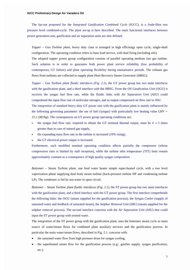
The lay-out proposed for the Integrated Gasification Combined Cycle (IGCC), is a Joule-Hirn two
pressure level combined-cycle. The plant set-up is here described. The main functional interfaces between
power generation unit, gasificaton and air separation units are also defined.
Topper – Gas Turbine plant, heavy duty class is arranged in high efficiengy open cycle, single-shaft
configuration. The operating condition refers to base load service, with dual firing (including oils).
The adopted topper power group configuration consists of parallel operating medium size gas turbine.
Such solution is in order to guarantee both power plant service reliability (low probability of
contemporary GT failure) and plant operating flexibility during mantainance periods. The exhaust gas
flows from turbines are collected to supply plant Heat Recovery Steam Generator (HRSG).
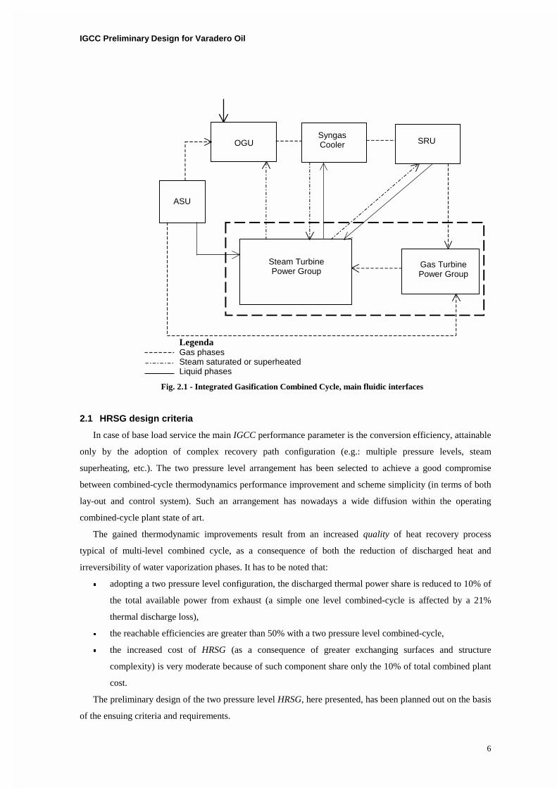
Topper – Gas Turbine plant fluidic interfaces (Fig. 2.1), the GT power group has two main interfaces
with the gasification plant, and a third interface with the HRSG. From the Oil Gasification Unit (OGU) it
receives the syngas fuel flow rate, while the fluidic links with Air Separation Unit (ASU) could
comprehend the input flow rate of molecular nitrogen, and as output compressed air flow rate to ASU.
The integration of standard heavy duty GT power unit with the gasification plant is mainly influenced by
the following governing parameter: the use of fuel (syngas) with particularly low heating value LHV =
15.1 (MJ/kg). The consequences on GT power group operating conditions are:
� the syngas fuel flow rate, required to obtain the GT nominal thermal output, must be 4 � 5 times
greater than in case of natural gas supply,
� the expanding mass flow rate in the turbine is increased (10% rising),
� the GT electrical power output is increased.
Furthermore, such modified nominal operating condition affects partially the compressor (whose
compression ratio is limited by stall inception), while the turbine inlet temperature (TIT) limit remain
approximately constant as a consequence of high quality syngas composition.
Bottomer – Steam Turbine plant, one feed water heater simple super-heated cycle, with a two level
vaporization phase supplying dual body steam turbine (back-pressure turbine HP and condensing turbine
LP). The condenser is fed by sea-water in open circuit.
Bottomer – Steam Turbine plant fluidic interfaces (Fig. 2.1), the ST power group has two main interfaces
with the gasification plant, and a third interface with the GT power group. The first interface comprehends
the following links: the OGU (steam supplied for the gasification process), the Syngas Cooler (supply of
saturated water and feedback of saturated steam), the Sulphur Removal Unit (SRU) (steam supplied for the
sulphur removal process). The second interface concerns with the Air Separation Unit (ASU) that could
input the ST power group with treated water.
The integration of the ST power group with the gasification plant, uses the bottomer steam cycle as main
source of water/steam flows for combined plant auxiliary services and the gasification process. In
particular the main water/steam flows, described in Fig. 2.1, concerns with:
� the saturated water flow from high pressure drum for syngas cooling,
� the superheated steam flow for the gasification process (e.g.: gasifier supply, syngas purification,
etc.).
IGCC Preliminary Design for Varadero Oil
6
Fig. 2.1 - Integrated Gasification Combined Cycle, main fluidic interfaces
2.1 HRSG design criteria
In case of base load service the main IGCC performance parameter is the conversion efficiency, attainable
only by the adoption of complex recovery path configuration (e.g.: multiple pressure levels, steam
superheating, etc.). The two pressure level arrangement has been selected to achieve a good compromise
between combined-cycle thermodynamics performance improvement and scheme simplicity (in terms of both
lay-out and control system). Such an arrangement has nowadays a wide diffusion within the operating
combined-cycle plant state of art.
The gained thermodynamic improvements result from an increased quality of heat recovery process
typical of multi-level combined cycle, as a consequence of both the reduction of discharged heat and
irreversibility of water vaporization phases. It has to be noted that:
� adopting a two pressure level configuration, the discharged thermal power share is reduced to 10% of
the total available power from exhaust (a simple one level combined-cycle is affected by a 21%
thermal discharge loss),
� the reachable efficiencies are greater than 50% with a two pressure level combined-cycle,
� the increased cost of HRSG (as a consequence of greater exchanging surfaces and structure
complexity) is very moderate because of such component share only the 10% of total combined plant
cost.
The preliminary design of the two pressure level HRSG, here presented, has been planned out on the basis
of the ensuing criteria and requirements.
ASU
OGU Syngas Cooler SRU
Steam Turbine Power Group
Gas Turbine Power Group
Legenda Gas phases Steam saturated or superheated Liquid phases
IGCC Preliminary Design for Varadero Oil
7
� The high pressure level (about 90 bar) has been fixed in order to reach a good compromise between
the thermodynamic cycle improvement (measured kW/bar) and component structural simplicity.
� The low pressure level (about 20 bar) has been defined in order to optimized the HRSG exchanging
efficiency, because its moderate influence on CCP power.
� The superheated steam temperature (about 520°C) has been fixed in order to minimized the heat
transfer surfaces, increasing the high pressure exchanged heat flux share.
� The discharge exhaust temperature at the stack hasn’t inferior limit specified to avoid the acid
condensate formation (exhaust originate from combustion of desulphurized gaseous fuel with excess
air); it’s advisable to design the HRSG in order to obtain discharge temperature in the range (120°C �
90°C).
� The steam limit conditions (90 bar, 520°C) corresponds to small power steam plant, tipically adopted
for combined-cycle scheme.
� The condensation condition (0.1 bar) refers to sea water operating as cooling fluid in open circuit.
� The de-aerating unit is provided directly from low temperature exhaust heat, thus allowing the
elimination of regenerative steam bleeding from turbine because of its thermodynamic non-sense
within combined cycle.
The HRSG has an orizontal configuration, with natural circulation obtained by several downcomers which
also provide additional structural support for the heat transfer surface and steam drum. Such configuration
enable the achievement of greatest component reliability and flexibiltiy in off-design operating condition, due
to the lack of pumps, valves and control.
As far as the thermal top-bottom link is concerned, the chosen bottomer configuration results in the above
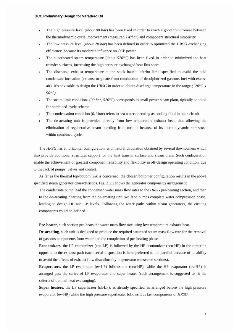
specified steam generator characteristics. Fig. 2.1.1 shows the generator components arrangement.
The condensate pump lead the condensed water mass flow rates to the HRSG pre-heating section, and then
to the de-areating. Starting from the de-areating unit two feed pumps complete water compression phase,
leading to design HP and LP levels. Following the water paths within steam generators, the ensuing
components could be defined.
Pre-heater, such section pre-heats the water mass flow rate using low temperature exhaust heat.
De-areating, such unit is designed to produce the required saturated steam mass flow rate for the removal
of gaseous components from water and the completion of pre-heating phase.
Economizers, the LP economizer (eco-LP) is followed by the HP economizer (eco-HP) in the direction
opposite to the exhaust path (such serial disposition is here preferred to the parallel because of its ability
to avoid the effects of exhaust flow disuniformity in generator transverse sections).
Evaporators, the LP evaporator (ev-LP) follows the (eco-HP), while the HP evaporator (ev-HP) is
arranged past the series of LP evaporator and super heater (such arrangement is suggested to fit the
criteria of optimal heat exchanging).
Super heaters, the LP superheater (sh-LP), as already specified, is arranged before the high pressure
evaporator (ev-HP) while the high pressure superheater follows it as last components of HRSG.
IGCC Preliminary Design for Varadero Oil
8
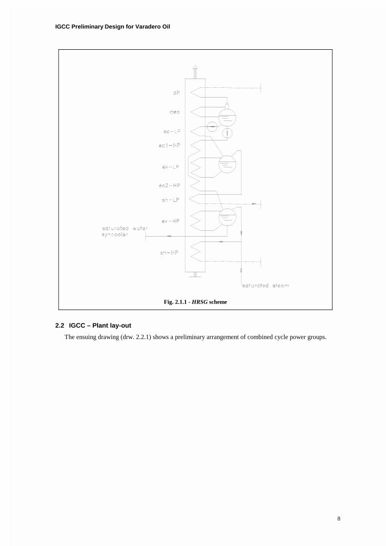
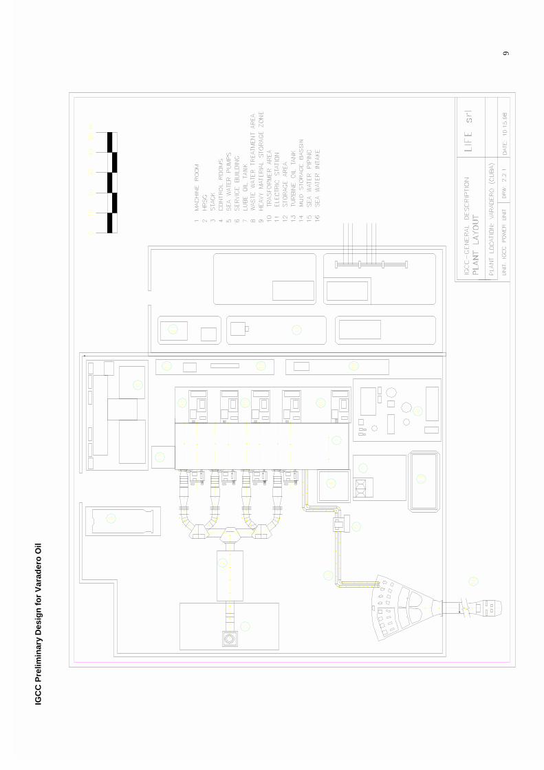
2.2 IGCC – Plant lay-out
The ensuing drawing (drw. 2.2.1) shows a preliminary arrangement of combined cycle power groups.
Fig. 2.1.1 - HRSG scheme
IGC
C P
relim
inar
y D
esig
n f
or
Var
ader
o O
il
9
IGCC Preliminary Design for Varadero Oil
10
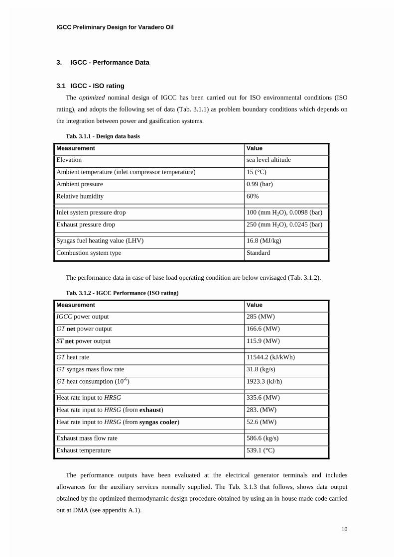
3. IGCC - Performance Data
3.1 IGCC - ISO rating
The optimized nominal design of IGCC has been carried out for ISO environmental conditions (ISO
rating), and adopts the following set of data (Tab. 3.1.1) as problem boundary conditions which depends on
the integration between power and gasification systems.
Tab. 3.1.1 - Design data basis
Measurement Value
Elevation sea level altitude
Ambient temperature (inlet compressor temperature) 15 (°C)
Ambient pressure 0.99 (bar)
Relative humidity 60%
Inlet system pressure drop 100 (mm H2O), 0.0098 (bar)
Exhaust pressure drop 250 (mm H2O), 0.0245 (bar)
Syngas fuel heating value (LHV) 16.8 (MJ/kg)
Combustion system type Standard
The performance data in case of base load operating condition are below envisaged (Tab. 3.1.2).
Tab. 3.1.2 - IGCC Performance (ISO rating)
Measurement Value
IGCC power output 285 (MW)
GT net power output 166.6 (MW)
ST net power output 115.9 (MW)
GT heat rate 11544.2 (kJ/kWh)
GT syngas mass flow rate 31.8 (kg/s)
GT heat consumption (10-6) 1923.3 (kJ/h)
Heat rate input to HRSG 335.6 (MW)
Heat rate input to HRSG (from exhaust) 283. (MW)
Heat rate input to HRSG (from syngas cooler) 52.6 (MW)
Exhaust mass flow rate 586.6 (kg/s)
Exhaust temperature 539.1 (°C)
The performance outputs have been evaluated at the electrical generator terminals and includes
allowances for the auxiliary services normally supplied. The Tab. 3.1.3 that follows, shows data output
obtained by the optimized thermodynamic design procedure obtained by using an in-house made code carried
out at DMA (see appendix A.1).
IGCC Preliminary Design for Varadero Oil
11
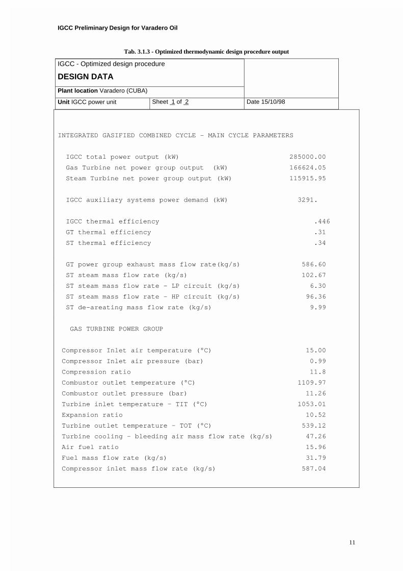
Tab. 3.1.3 - Optimized thermodynamic design procedure output
IGCC - Optimized design procedure
DESIGN DATA
Plant location Varadero (CUBA)
Unit IGCC power unit Sheet 1 of 2 Date 15/10/98
INTEGRATED GASIFIED COMBINED CYCLE - MAIN CYCLE PARAMETERS
IGCC total power output (kW) 285000.00
Gas Turbine net power group output (kW) 166624.05
Steam Turbine net power group output (kW) 115915.95
IGCC auxiliary systems power demand (kW) 3291.
IGCC thermal efficiency .446
GT thermal efficiency .31
ST thermal efficiency .34
GT power group exhaust mass flow rate(kg/s) 586.60
ST steam mass flow rate (kg/s) 102.67
ST steam mass flow rate - LP circuit (kg/s) 6.30
ST steam mass flow rate - HP circuit (kg/s) 96.36
ST de-areating mass flow rate (kg/s) 9.99
GAS TURBINE POWER GROUP
Compressor Inlet air temperature (°C) 15.00
Compressor Inlet air pressure (bar) 0.99
Compression ratio 11.8
Combustor outlet temperature (°C) 1109.97
Combustor outlet pressure (bar) 11.26
Turbine inlet temperature - TIT (°C) 1053.01
Expansion ratio 10.52
Turbine outlet temperature - TOT (°C) 539.12
Turbine cooling - bleeding air mass flow rate (kg/s) 47.26
Air fuel ratio 15.96
Fuel mass flow rate (kg/s) 31.79
Compressor inlet mass flow rate (kg/s) 587.04
IGCC Preliminary Design for Varadero Oil
12
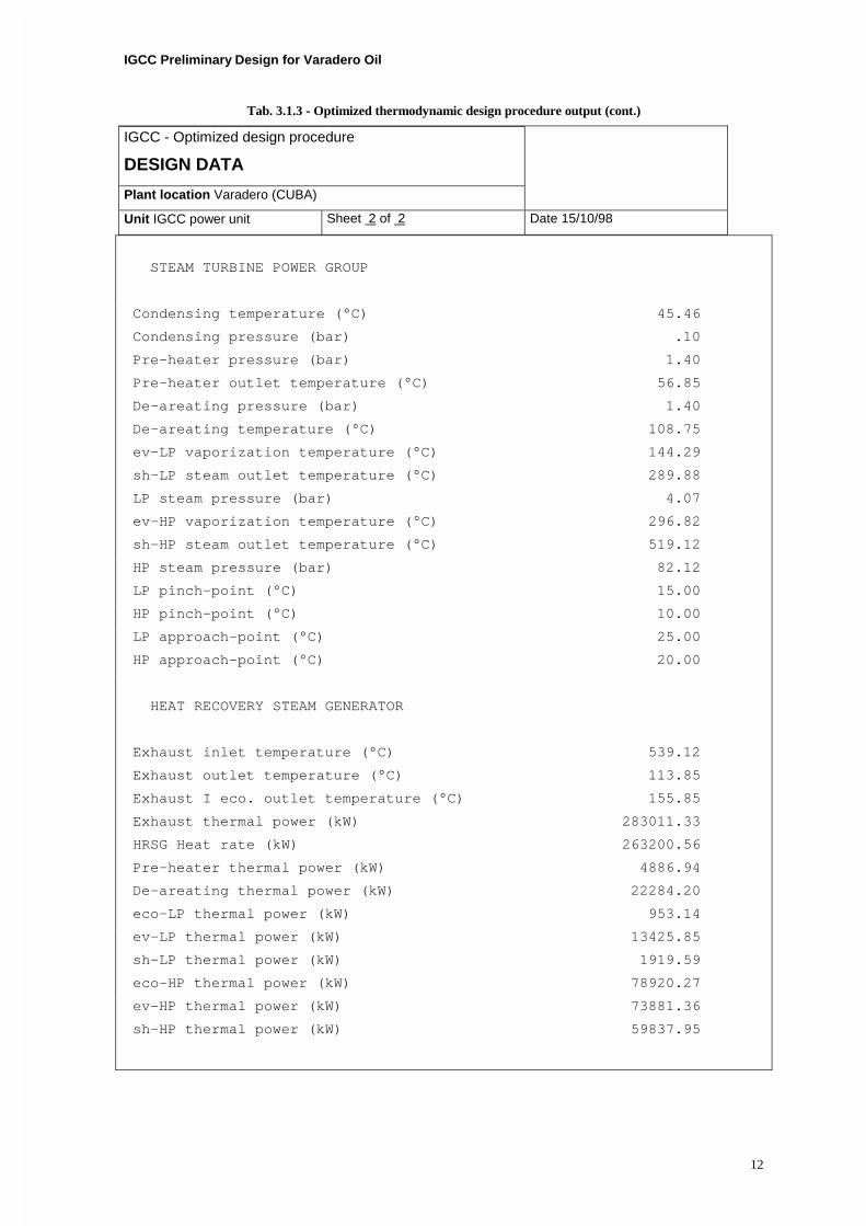
Tab. 3.1.3 - Optimized thermodynamic design procedure output (cont.)
IGCC - Optimized design procedure
DESIGN DATA
Plant location Varadero (CUBA)
Unit IGCC power unit Sheet 2 of 2 Date 15/10/98
STEAM TURBINE POWER GROUP
Condensing temperature (°C) 45.46
Condensing pressure (bar) .10
Pre-heater pressure (bar) 1.40
Pre-heater outlet temperature (°C) 56.85
De-areating pressure (bar) 1.40
De-areating temperature (°C) 108.75
ev-LP vaporization temperature (°C) 144.29
sh-LP steam outlet temperature (°C) 289.88
LP steam pressure (bar) 4.07
ev-HP vaporization temperature (°C) 296.82
sh-HP steam outlet temperature (°C) 519.12
HP steam pressure (bar) 82.12
LP pinch-point (°C) 15.00
HP pinch-point (°C) 10.00
LP approach-point (°C) 25.00
HP approach-point (°C) 20.00
HEAT RECOVERY STEAM GENERATOR
Exhaust inlet temperature (°C) 539.12
Exhaust outlet temperature (°C) 113.85
Exhaust I eco. outlet temperature (°C) 155.85
Exhaust thermal power (kW) 283011.33
HRSG Heat rate (kW) 263200.56
Pre-heater thermal power (kW) 4886.94
De-areating thermal power (kW) 22284.20
eco-LP thermal power (kW) 953.14
ev-LP thermal power (kW) 13425.85
sh-LP thermal power (kW) 1919.59
eco-HP thermal power (kW) 78920.27
ev-HP thermal power (kW) 73881.36
sh-HP thermal power (kW) 59837.95
IGCC Preliminary Design for Varadero Oil
13
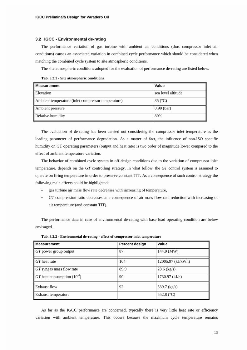
3.2 IGCC - Environmental de-rating
The performance variation of gas turbine with ambient air conditions (thus compressor inlet air
conditions) causes an associated variation in combined cycle performance which should be considered when
matching the combined cycle system to site atmospheric conditions.
The site atmospheric conditions adopted for the evaluation of performance de-rating are listed below.
Tab. 3.2.1 - Site atmospheric conditions
Measurement Value
Elevation sea level altitude
Ambient temperature (inlet compressor temperature) 35 (°C)
Ambient pressure 0.99 (bar)
Relative humidity 80%
The evaluation of de-rating has been carried out considering the compressor inlet temperature as the
leading parameter of performance degradation. As a matter of fact, the influence of non-ISO specific
humidity on GT operating parameters (output and heat rate) is two order of magnitude lower compared to the
effect of ambient temperature variation.
The behavior of combined cycle system in off-design conditions due to the variation of compressor inlet
temperature, depends on the GT controlling strategy. In what follow, the GT control system is assumed to
operate on firing temperature in order to preserve constant TIT. As a consequence of such control strategy the
following main effects could be highlighted:
� gas turbine air mass flow rate decreases with increasing of temperature,
� GT compression ratio decreases as a consequence of air mass flow rate reduction with increasing of
air temperature (and constant TIT).
The performance data in case of environmental de-rating with base load operating condition are below
envisaged.
Tab. 3.2.2 - Environmetal de-rating - effect of compressor inlet temperature
Measurement Percent design Value
GT power group output 87 144.9 (MW)
GT heat rate 104 12005.97 (kJ/kWh)
GT syngas mass flow rate 89.9 28.6 (kg/s)
GT heat consumption (10-6) 90 1730.97 (kJ/h)
Exhaust flow 92 539.7 (kg/s)
Exhaust temperature 552.8 (°C)
As far as the IGCC performance are concerned, typically there is very little heat rate or efficiency
variation with ambient temperature. This occurs because the maximum cycle temperature remains
IGCC Preliminary Design for Varadero Oil
14
approximately constant and the performance variations simply reflect the variation in efficiencies of
components with varying operating conditions (e.g.: the GT power group).
3.3 IGCC - Performance degradation
The IGCC are afflicted by a performance loss during extended period operational periods mainly due to
GT power group compressor fouling. For such reason during normal operation the performance loss is
minimized by periodic on-line and off-line compressor water washes.
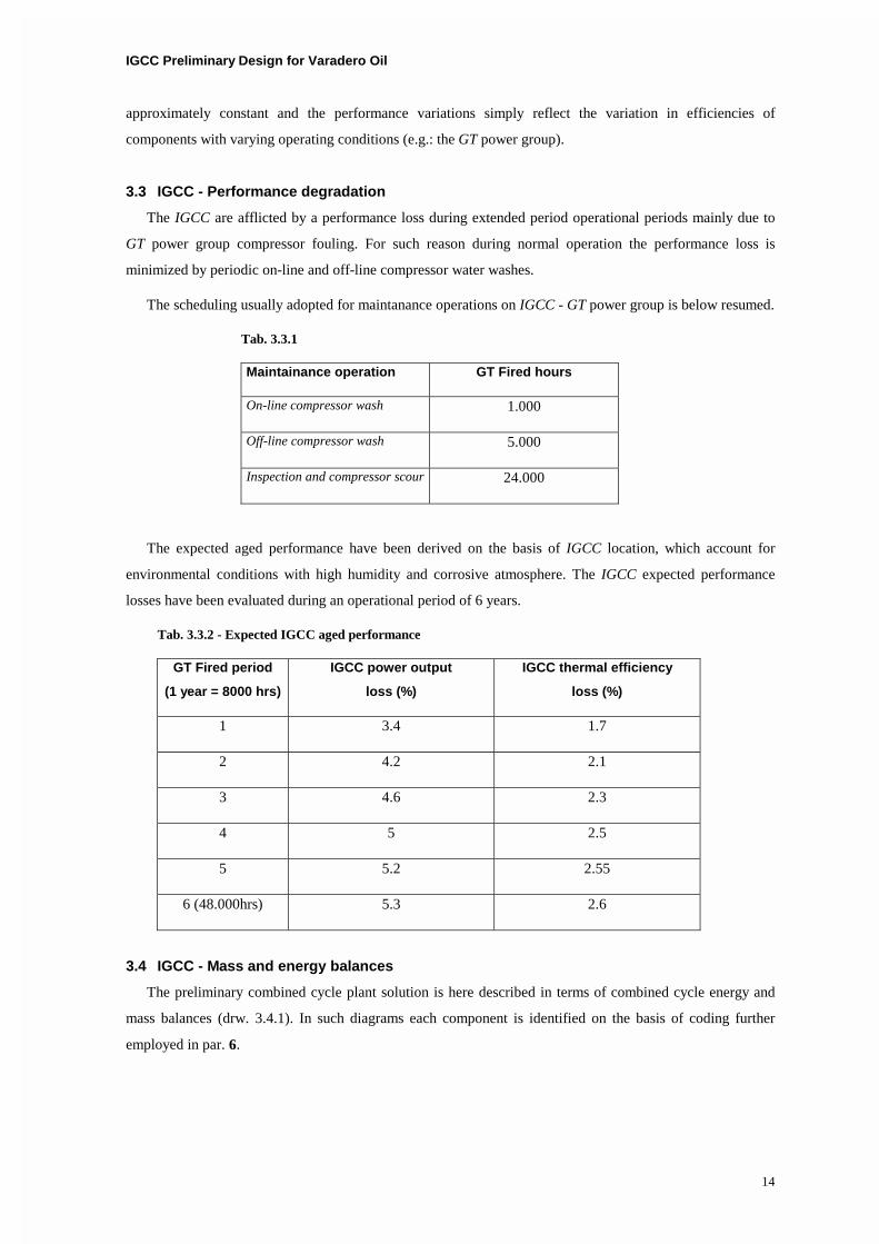
The scheduling usually adopted for maintanance operations on IGCC - GT power group is below resumed.
Tab. 3.3.1
Maintainance operation GT Fired hours
On-line compressor wash 1.000
Off-line compressor wash 5.000
Inspection and compressor scour 24.000
The expected aged performance have been derived on the basis of IGCC location, which account for
environmental conditions with high humidity and corrosive atmosphere. The IGCC expected performance
losses have been evaluated during an operational period of 6 years.
Tab. 3.3.2 - Expected IGCC aged performance
GT Fired period
(1 year = 8000 hrs)
IGCC power output
loss (%)
IGCC thermal efficiency
loss (%)
1 3.4 1.7
2 4.2 2.1
3 4.6 2.3
4 5 2.5
5 5.2 2.55
6 (48.000hrs) 5.3 2.6
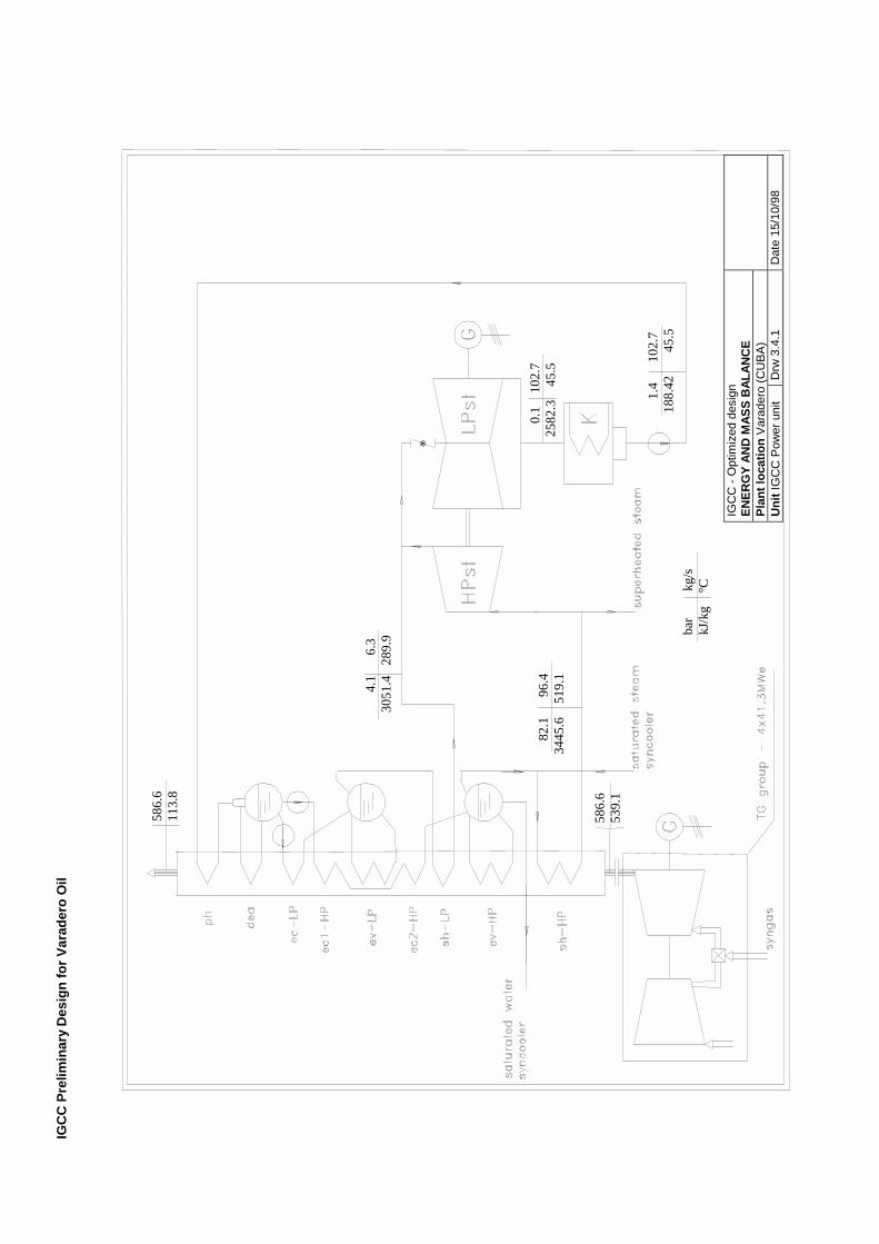
3.4 IGCC - Mass and energy balances
The preliminary combined cycle plant solution is here described in terms of combined cycle energy and
mass balances (drw. 3.4.1). In such diagrams each component is identified on the basis of coding further
employed in par. 6.
IGC
C P
relim
inar
y D
esig
n f
or
Var
ader
o O
il
IGC
C -
Opt
imiz
ed d
esig
n E
NE
RG
Y A
ND
MA
SS
BA
LA
NC
E
Pla
nt
loca
tio
n V
arad
ero
(CU
BA
)
Un
it IG
CC
Pow
er u
nit
Drw
3.4
.1
Dat
e 15
/10/
98
586
.6
113
.8
4.1
6
.3
3051
.4
289.
9
586
.6
539
.1
8
2.1
9
6.4
344
5.6
51
9.1
bar
kg/
s kJ
/kg
°C
0
.1
102
.7
2582
.3
45.
5
1
.4
10
2.7
188.
42
4
5.5
IGCC Preliminary Design for Varadero Oil
16
4. IGCC - Plant operating strategy
The combined cycle system control requirements involve the following main control loops (Tab.
4.0.1).
Tab. 4.0.1 – IGCC main control loops
Control loops – Components Control actions
GT control Fuel
Compressor inlet guide vane
HRSG Feedwater
Economizer recirculation
Damper modulation
Superheated steam maximum temperature
De-areating hotwell level
ST Steam pressure (HP and LP levels)
Steam by-pass valve
Speed (starting and synchronizing)
Auxiliaries Condensate pump recirculation
Boiler feed-water pump recirculation
Condenser hotwell level
In the IGCC control strategy the GT power group plays the leading role in the modulation of
power outputs, and as a consequence the HRSG and ST power group simply follow the gas turbines
and generate power depending on the amount of heat received from the topper itself.
4.1 Gas Turbine control
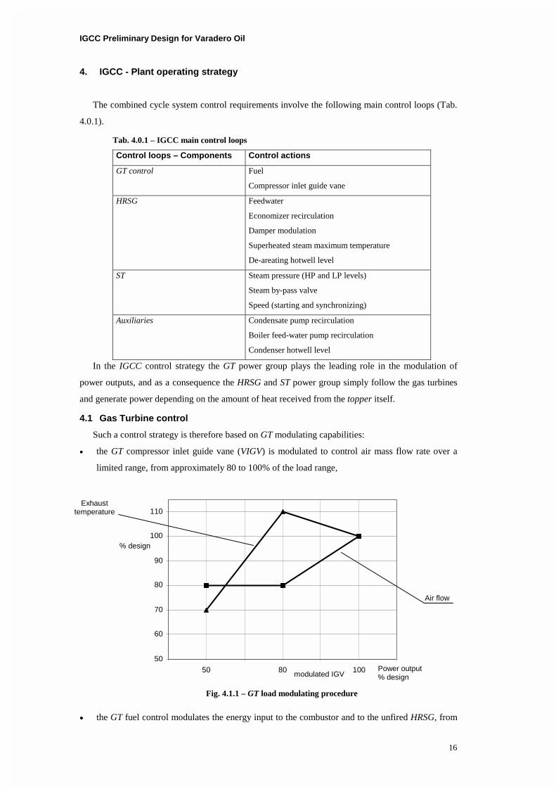
Such a control strategy is therefore based on GT modulating capabilities:
� the GT compressor inlet guide vane (VIGV) is modulated to control air mass flow rate over a
limited range, from approximately 80 to 100% of the load range,
� the GT fuel control modulates the energy input to the combustor and to the unfired HRSG, from
50
60
70
80
90
100
110
50 80 100
Air flow
Exhaust temperature
modulated IGV
Fig. 4.1.1 – GT load modulating procedure
Power output % design
% design
IGCC Preliminary Design for Varadero Oil
17
approximately 50 to 80% of the load range.
An example of GT modulating procedure is reported in Fig. 4.1.1, with reference to heavy-duty,
open cycle one-shaft configuration. It should be noted that the reduction of air mass flow rate during
IGV modulation, results in increased exhaust temperature. As a consequence of such behavior the
thermal recovery is improved and the stack thermal losses decreases, due to the higher exhaust
temperature at the inlet of HRSG that results in exhaust heat exchanging line with increased slope.
4.2 HRSG and Steam Turbine control
The control strategy for HRSG and steam power group load modulation includes the ensuing
capabilities.
� The control of super-heated steam temperature with water injection, in order to carried out
the steam temperation.
� The stabilization of HP steam circuit pressure to nominal value, in order to produce high
pressure superheated steam at constant pressure and temperature durig load modulation to
supply the gasification process (Oil Gasification Unit). The pressure level at the inlet section
of HP steam turbine is controlled acting via a lamination valve.
� The stabilization of LP steam circuit pressure to nominal value, in order to preserve during
the modulation the LP steam drum stability condition. In particular, the control of the
pressure of LP steam circuit allows to operate at nominal pressure conditon the condensate
pump, the pre-heater and the de-areating portion of water circuit thus gaining constant inlet
pressure for the feed-water pumps. The pressure level at the inlet section of LP steam turbine
is controlled acting via a lamination valve.
4.3 Plant operative control loops
The IGCC plant is considered shared into a number of process group (PG), each controlling a
zone of the plant. The general performance carried out by each PG are below listed:
� start and stop of motors, modulation of pumps,
� control of valves,
� check motors and valves manoeuvring on the basis of pre-imposed control logic,
� check and control of alarm signals,
� limit the set values changes within the permissible range,
� check the sequence logic for PGs starting,
� preventive check for the operating conditions that allow PG start.
A short description of the main IGCC plant Process Groups follows.
Gas turbine GT
Starts and stops the turbine.
Controls loading, unloading and synchronizing.
IGCC Preliminary Design for Varadero Oil
18
Controls VIGV position.
Controls fuel mass flow rate.
Oil system
Starts and stops the lube oil and hydraulic oil pumps.
Controls the emergency oil pump.
Condensate
Controls the condensate pumps and valves.
Level control in condenser hotwell.
Feedwater
Controls the feedwater pumps.
Level control in feedwater tank (de-areating hotwell).
HRSG
Drums level control.
Temperature control of superheated steam.
Steam turbine ST
By-pass valve control during startup with respect to boiler pressure and steam pressure.
Control of steam temperation.
Blow-off valve control.
Control of lamination valves on HP and LP steam lines.
Overall logic
Starts the Process Groups in the correct order.
Controls the sequence of Process Groups stopping to achieve the plant stop.
Controls the correctness of starting conditions.
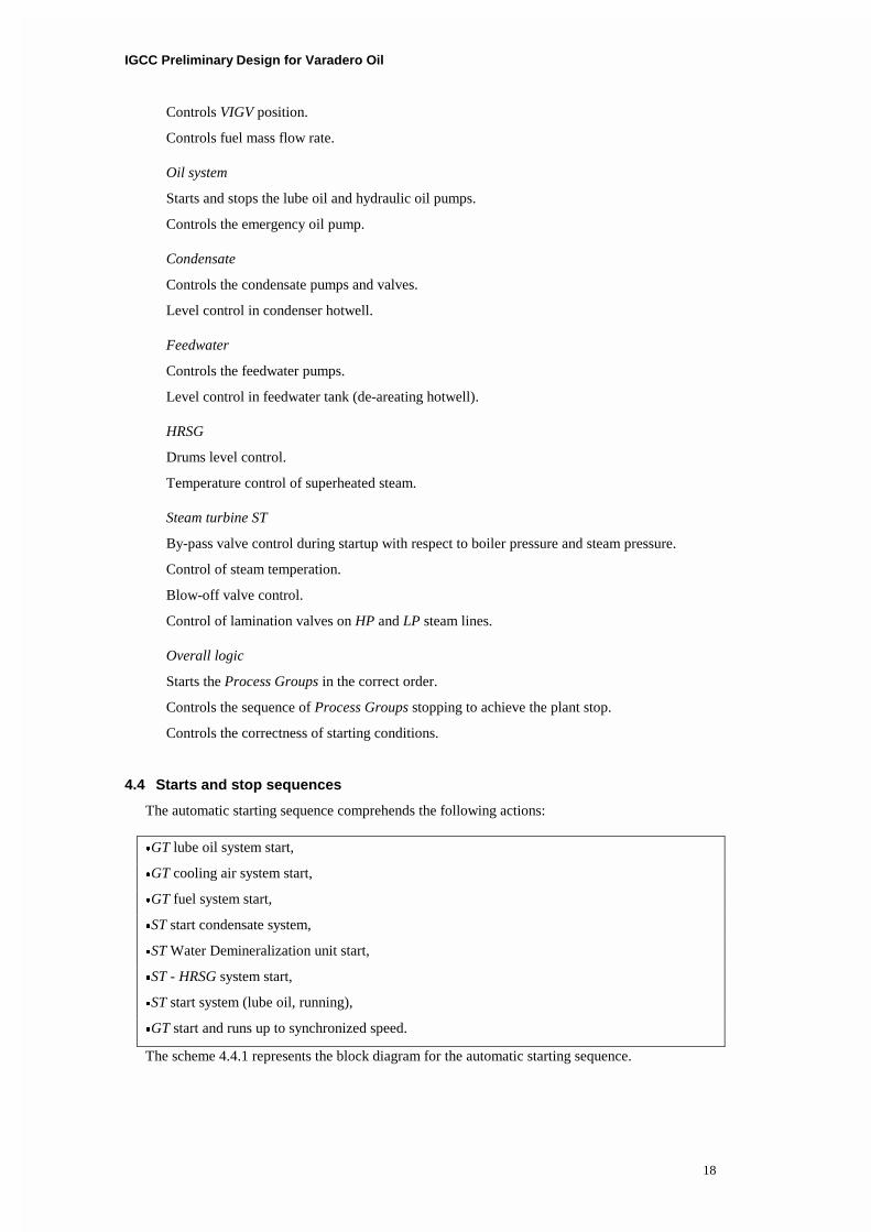
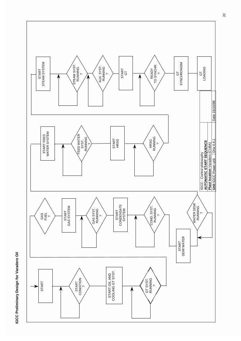
4.4 Starts and stop sequences
The automatic starting sequence comprehends the following actions:
�GT lube oil system start,
�GT cooling air system start,
�GT fuel system start,
�ST start condensate system,
�ST Water Demineralization unit start,
�ST - HRSG system start,
�ST start system (lube oil, running),
�GT start and runs up to synchronized speed.
The scheme 4.4.1 represents the block diagram for the automatic starting sequence.

IGCC Preliminary Design for Varadero Oil
19
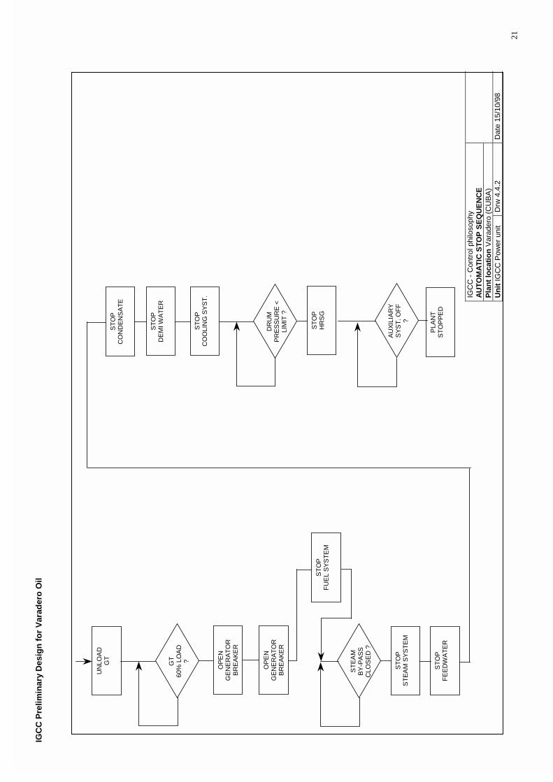
The automatic stop sequence comprehends the following actions:
�GT unload,
�open electric generator circuit breaker,
�GT stop,
�ST stop system,
�ST stop feedwater,
�ST stop condensate,
�ST stop Water Demineralization unit,
�ST system stop (lube oil),
�GT lube oil system stop,
�GT cooling system stop,
�ST - HRSG stop.
The scheme 4.4.2 represents the block diagram for the automatic stop sequence.
IGC
C P
relim
inar
y D
esig
n f
or
Var
ader
o O
il
20
ST
AR
T O
ILG
T S
YS
TE
M
OIL
SY
ST
.R
UN
NIN
G?
ST
AR
T
ST
AR
TC
ON
DIT
ION
?
ST
AR
TG
AS
SY
ST
EM
GA
S S
YS
T.
RU
NN
ING
?
GA
SF
UE
L?
ST
AR
TC
ON
DE
NS
AT
ES
YS
TE
M
CO
ND
. SY
ST
.R
UN
NIN
G?
ST
AR
TH
RS
G
HR
SG
RU
NN
ING
?
ST
AR
T F
EE
DW
AT
ER
SY
ST
EM
FE
ED
WA
TE
RS
YS
T.
RU
NN
ING
?
ST
AR
TG
T
RE
AD
YT
O S
YN
CH
R.
?
ST
AR
TS
TE
AM
SY
ST
EM
ST
EA
M S
YS
T.
RU
NN
ING
?
AU
X.
SY
ST
.R
UN
NIN
G?
ST
AR
TD
EM
I WA
TE
R
WA
TE
R D
EM
IR
UN
NIN
G?
GT
SY
NC
HR
ON
ISM
GT
LOA
DIN
G
ST
AR
T O
IL A
ND
C
OO
LIN
G G
T S
YS
T.
GT
SY
ST
. R
UN
NIN
G
?
IGC
C -
Con
trol
phi
loso
phy
AU
TO
MA
TIC
ST
AR
T S
EQ
UE
NC
E
Pla
nt
loca
tio
n V
arad
ero
(CU
BA
)
Un
it IG
CC
Pow
er u
nit
Drw
4.4
.1
Dat
e 15
/10/
98
IGC
C P
relim
inar
y D
esig
n f
or
Var
ader
o O
il
21
OP
EN
GE
NE
RA
TO
RB
RE
AK
ER
ST
EA
MB
Y-P
AS
SC
LOS
ED
?
UN
LOA
DG
T
GT
60%
LO
AD
?
ST
OP
HR
SG
AU
XIL
IAR
YS
YS
T. O
FF
?
ST
OP
CO
OLI
NG
SY
ST
.
DR
UM
PR
ES
SU
RE
<LI
MIT
?
ST
OP
FU
EL
SY
ST
EM
OP
EN
GE
NE
RA
TO
RB
RE
AK
ER
ST
OP
ST
EA
M S
YS
TE
M
ST
OP
FE
ED
WA
TE
R
ST
OP
CO
ND
EN
SA
TE
ST
OP
DE
MI W
AT
ER
PLA
NT
ST
OP
PE
D
IG
CC
- C
ontr
ol p
hilo
soph
y A
UT
OM
AT
IC S
TO
P S
EQ
UE
NC
E
Pla
nt
loca
tio
n V
arad
ero
(CU
BA
)
Un
it IG
CC
Pow
er u
nit
Drw
4.4
.2
Dat
e 15
/10/
98

IGCC Preliminary Design for Varadero Oil
22
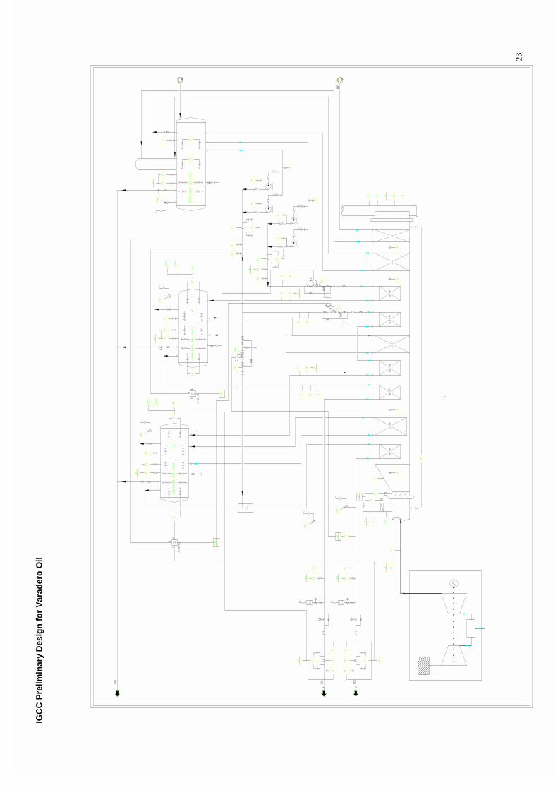
5. IGCC - P&I diagrams
The process description is showed in drw. 5.0.1.
IGC
C P
relim
inar
y D
esig
n f
or
Var
ader
o O
il
23
IGCC Preliminary Design for Varadero Oil
24
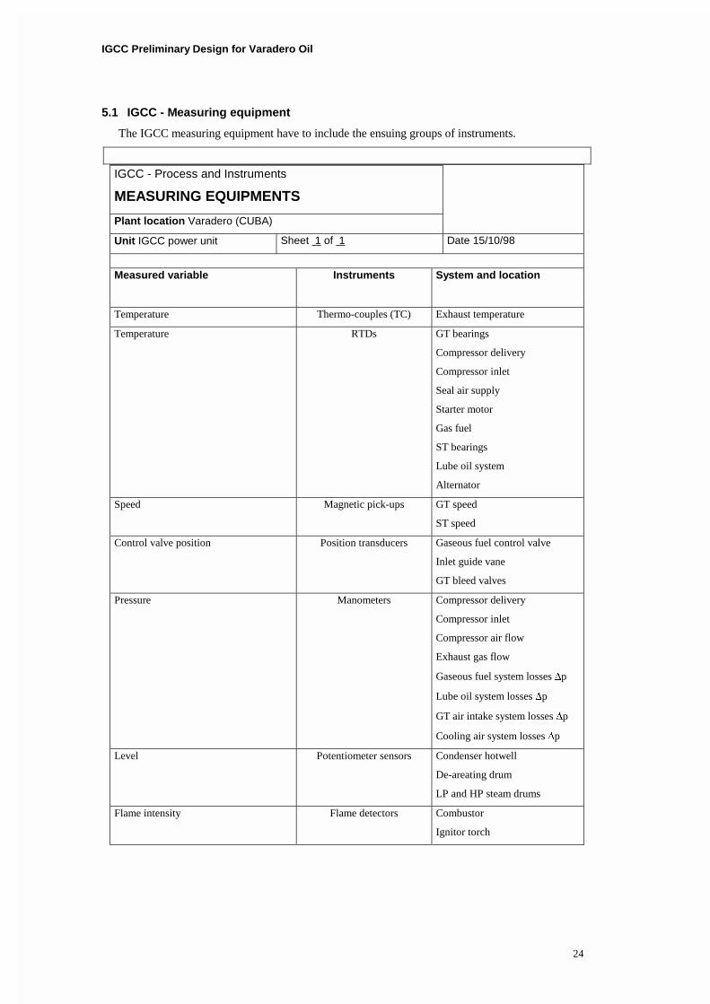
5.1 IGCC - Measuring equipment
The IGCC measuring equipment have to include the ensuing groups of instruments.
IGCC - Process and Instruments
MEASURING EQUIPMENTS
Plant location Varadero (CUBA)
Unit IGCC power unit Sheet 1 of 1 Date 15/10/98
Measured variable
Instruments System and location
Temperature Thermo-couples (TC) Exhaust temperature
Temperature RTDs GT bearings
Compressor delivery
Compressor inlet
Seal air supply
Starter motor
Gas fuel
ST bearings
Lube oil system
Alternator
Speed Magnetic pick-ups GT speed
ST speed
Control valve position Position transducers Gaseous fuel control valve
Inlet guide vane
GT bleed valves
Pressure Manometers Compressor delivery
Compressor inlet
Compressor air flow
Exhaust gas flow
Gaseous fuel system losses �p
Lube oil system losses �p
GT air intake system losses �p
Cooling air system losses �p
Level Potentiometer sensors Condenser hotwell
De-areating drum
LP and HP steam drums
Flame intensity Flame detectors Combustor
Ignitor torch
IGCC Preliminary Design for Varadero Oil
25
6. IGCC - Requirements
The paragraph aims to report the description of preliminary plant set-up, through the
requirements of its components.
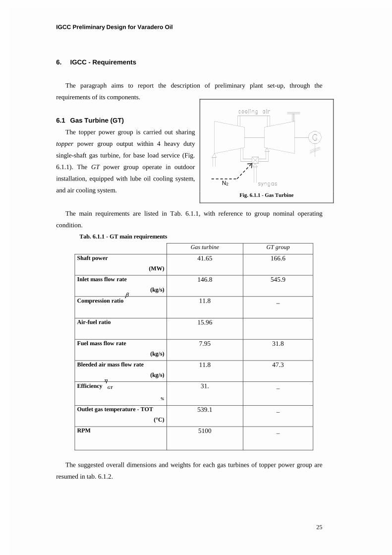
6.1 Gas Turbine (GT)
The topper power group is carried out sharing
topper power group output within 4 heavy duty
single-shaft gas turbine, for base load service (Fig.
6.1.1). The GT power group operate in outdoor
installation, equipped with lube oil cooling system,
and air cooling system.
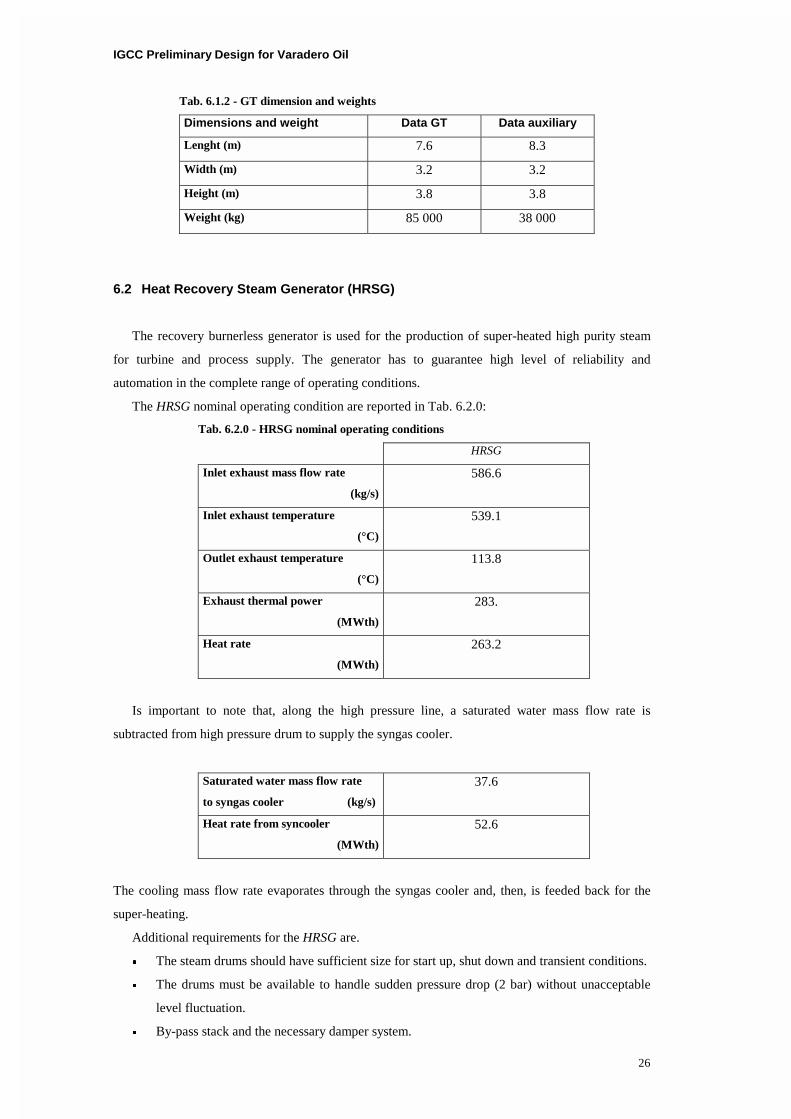
The main requirements are listed in Tab. 6.1.1, with reference to group nominal operating
condition.
Tab. 6.1.1 - GT main requirements
Gas turbine GT group
Shaft power
(MW)
41.65 166.6
Inlet mass flow rate
(kg/s)
146.8 545.9
Compression ratio ��
11.8 _
Air-fuel ratio
15.96
Fuel mass flow rate
(kg/s)
7.95 31.8
Bleeded air mass flow rate
(kg/s)
11.8 47.3
Efficiency ��
GT
%
31. _
Outlet gas temperature - TOT
(°C)
539.1 _
RPM 5100 _
The suggested overall dimensions and weights for each gas turbines of topper power group are
resumed in tab. 6.1.2.
Fig. 6.1.1 - Gas Turbine
N2
IGCC Preliminary Design for Varadero Oil
26
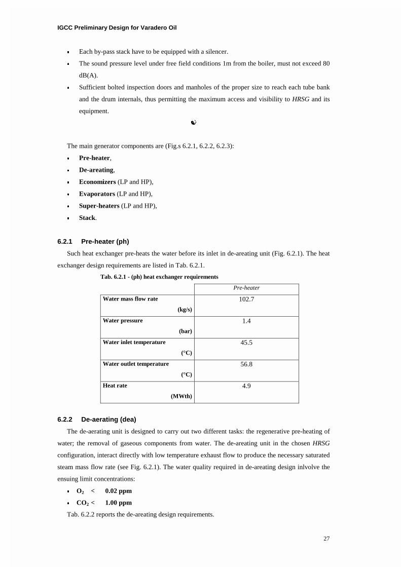
Tab. 6.1.2 - GT dimension and weights
Dimensions and weight Data GT Data auxiliary
Lenght (m) 7.6 8.3
Width (m) 3.2 3.2
Height (m) 3.8 3.8
Weight (kg) 85 000 38 000
6.2 Heat Recovery Steam Generator (HRSG)
The recovery burnerless generator is used for the production of super-heated high purity steam
for turbine and process supply. The generator has to guarantee high level of reliability and
automation in the complete range of operating conditions.
The HRSG nominal operating condition are reported in Tab. 6.2.0:
Tab. 6.2.0 - HRSG nominal operating conditions
HRSG
Inlet exhaust mass flow rate
(kg/s)
586.6
Inlet exhaust temperature
(°C)
539.1
Outlet exhaust temperature
(°C)
113.8
Exhaust thermal power
(MWth)
283.
Heat rate
(MWth)
263.2
Is important to note that, along the high pressure line, a saturated water mass flow rate is
subtracted from high pressure drum to supply the syngas cooler.
Saturated water mass flow rate
to syngas cooler (kg/s)
37.6
Heat rate from syncooler
(MWth)
52.6
The cooling mass flow rate evaporates through the syngas cooler and, then, is feeded back for the
super-heating.
Additional requirements for the HRSG are.
� The steam drums should have sufficient size for start up, shut down and transient conditions.
� The drums must be available to handle sudden pressure drop (2 bar) without unacceptable
level fluctuation.
� By-pass stack and the necessary damper system.
IGCC Preliminary Design for Varadero Oil
27
� Each by-pass stack have to be equipped with a silencer.
� The sound pressure level under free field conditions 1m from the boiler, must not exceed 80
dB(A).
� Sufficient bolted inspection doors and manholes of the proper size to reach each tube bank
and the drum internals, thus permitting the maximum access and visibility to HRSG and its
equipment.
�
The main generator components are (Fig.s 6.2.1, 6.2.2, 6.2.3):
� Pre-heater,
� De-areating,
� Economizers (LP and HP),
� Evaporators (LP and HP),
� Super-heaters (LP and HP),
� Stack.
6.2.1 Pre-heater (ph)
Such heat exchanger pre-heats the water before its inlet in de-areating unit (Fig. 6.2.1). The heat
exchanger design requirements are listed in Tab. 6.2.1.
Tab. 6.2.1 - (ph) heat exchanger requirements
Pre-heater
Water mass flow rate
(kg/s)
102.7
Water pressure
(bar)
1.4
Water inlet temperature
(°C)
45.5
Water outlet temperature
(°C)
56.8
Heat rate
(MWth)
4.9
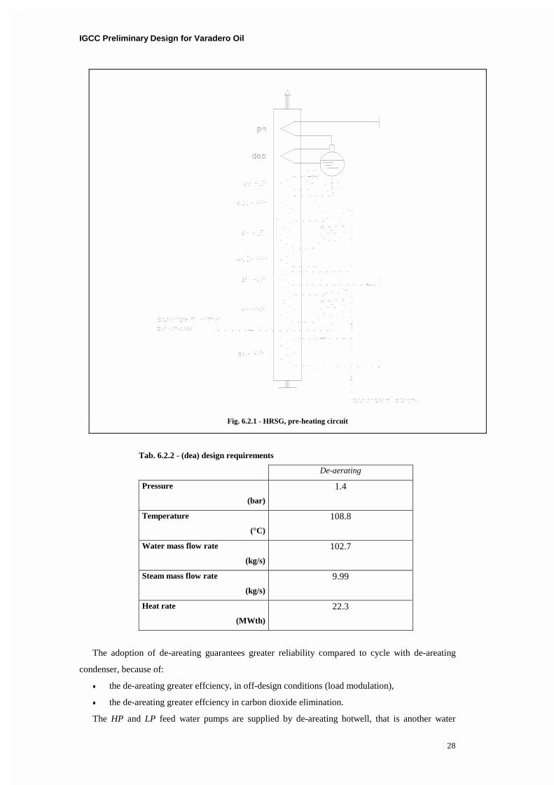
6.2.2 De-aerating (dea)
The de-aerating unit is designed to carry out two different tasks: the regenerative pre-heating of
water; the removal of gaseous components from water. The de-areating unit in the chosen HRSG
configuration, interact directly with low temperature exhaust flow to produce the necessary saturated
steam mass flow rate (see Fig. 6.2.1). The water quality required in de-areating design inlvolve the
ensuing limit concentrations:
� O2 < 0.02 ppm
� CO2 < 1.00 ppm
Tab. 6.2.2 reports the de-areating design requirements.
IGCC Preliminary Design for Varadero Oil
28
Tab. 6.2.2 - (dea) design requirements
De-aerating
Pressure
(bar)
1.4
Temperature
(°C)
108.8
Water mass flow rate
(kg/s)
102.7
Steam mass flow rate
(kg/s)
9.99
Heat rate
(MWth)
22.3
The adoption of de-areating guarantees greater reliability compared to cycle with de-areating
condenser, because of:
� the de-areating greater effciency, in off-design conditions (load modulation),
� the de-areating greater effciency in carbon dioxide elimination.
The HP and LP feed water pumps are supplied by de-areating hotwell, that is another water
Fig. 6.2.1 - HRSG, pre-heating circuit
IGCC Preliminary Design for Varadero Oil
29
storage volume in the HRSG.
6.2.3 Economizers (ec)
The eco-LP is installed at the end of exhaust path in HRSG (low temperature zone), while the
high pressure ones (eco-HP) are installed upstream. For such reason two limit phenomena have to be
considered in economizers design:
� inlet water temperatures to eco-LP and eco-HP, such temperatures have to be greater enough to
prevent cold exhaust gas condensation,
� outlet temperatures from eco-LP and eco-HP, in order to satisfy the approach interval to
vaporization temperatures thus avoiding an early vaporization.
In the proposed scheme the eco-HP is interfaced with the eco-LP by the low pressure steam
separator.
Tab. 6.2.3 - (ec) design requirements
Low Pressure - Steam High Pressure - Steam
Water mass flow
(kg/s)
6.3 96.4
Inlet Temperature
(°C)
108.8 108.8
Outlet Temperature
(°C)
144.3 296.8
Pressure
(bar)
4.1 82.1
Heat rate
(MWth)
0.953 80.9
6.2.4 Evaporators (ev)
The evaporators, ev-LP and ev-HP have the characteristics resumed in Tab. 6.2.4.
Tab. 6.2.4 - (ev) design requirements
Low Pressure - Steam High Pressure - Steam
Water mass flow
(kg/s)
6.3 96.4
Inlet Temperature
(°C)
144.3 296.8
Outlet Temperature
(°C)
144.3 296.8
Pressure
(bar)
4.1 82.1
Pinch-point
(°C)
15 15
Heat rate
(MWth)
13.4 78.9
IGCC Preliminary Design for Varadero Oil
30
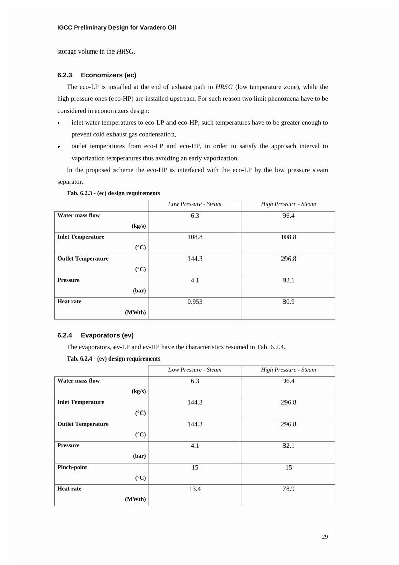
6.2.5 Super-heaters (sh)
The super-heaters sh-LP and sh-HP supply respectively LP and HP steam turbines with constant
temperature steam flow rate. Both the super-heating sections have a water injection system to control
maximum allowable steam temperature.
Tab. 6.2.5 - (sh) design requirements
Low Pressure - Steam High Pressure - Steam
Steam mass flow
(kg/s)
6.3 96.4
Inlet Temperature
(°C)
144.3 296.8
Outlet Temperature
(°C)
289.9 519.1
Pressure
(bar)
4.1 82.1
Approach point
(°C)
25 20
Heat rate
(MWth)
1.9 59.8
Fig. 6.2.2 - HRSG, low pressure steam circuit
IGCC Preliminary Design for Varadero Oil
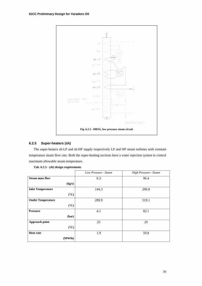
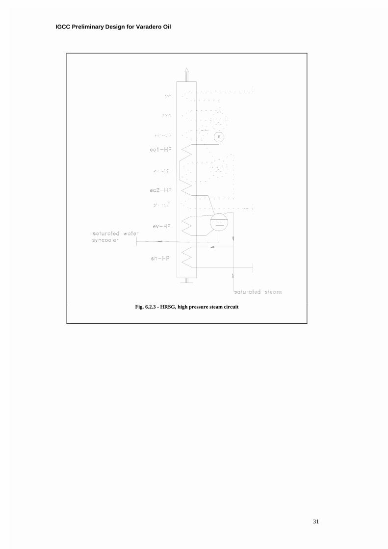
31
Fig. 6.2.3 - HRSG, high pressure steam circuit
IGCC Preliminary Design for Varadero Oil
32
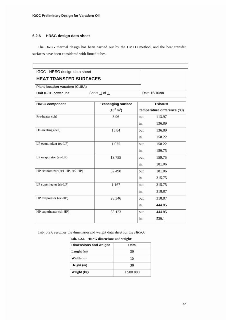
6.2.6 HRSG design data sheet
The HRSG thermal design has been carried out by the LMTD method, and the heat transfer
surfaces have been considered with finned tubes.
IGCC - HRSG design data sheet
HEAT TRANSFER SURFACES
Plant location Varadero (CUBA)
Unit IGCC power unit Sheet 1 of 1 Date 15/10/98
HRSG component Exchanging surface
(103 m2)
Exhaust
temperature difference (°C)
Pre-heater (ph) 3.96 out, 113.97
in, 136.89
De-areating (dea) 15.84 out, 136.89
in, 158.22
LP economizer (ec-LP) 1.075 out, 158.22
in, 159.75
LP evaporator (ev-LP) 13.755 out, 159.75
in, 181.06
HP economizer (ec1-HP, ec2-HP) 52.498 out, 181.06
in, 315.75
LP superheater (sh-LP) 1.167 out, 315.75
in, 318.87
HP evaporator (ev-HP) 28.346 out, 318.87
in, 444.85
HP superheater (sh-HP) 33.123 out, 444.85
in, 539.1
Tab. 6.2.6 resumes the dimension and weight data sheet for the HRSG.
Tab. 6.2.6 - HRSG dimensions and weights
Dimensions and weight Data
Lenght (m) 30
Width (m) 15
Height (m) 30
Weight (kg) 1 500 000
IGCC Preliminary Design for Varadero Oil
33
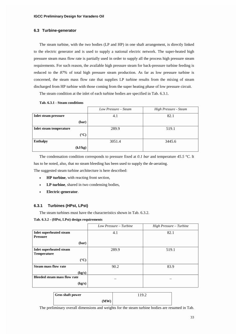
6.3 Turbine-generator
The steam turbine, with the two bodies (LP and HP) in one shaft arrangement, is directly linked
to the electric generator and is used to supply a national electric network. The super-heated high
pressure steam mass flow rate is partially used in order to supply all the process high pressure steam
requirements. For such reason, the available high pressure steam for back-pressure turbine feeding is
reduced to the 87% of total high pressure steam production. As far as low pressure turbine is
concerned, the steam mass flow rate that supplies LP turbine results from the mixing of steam
discharged from HP turbine with those coming from the super heating phase of low pressure circuit.
The steam condition at the inlet of each turbine bodies are specified in Tab. 6.3.1.
Tab. 6.3.1 - Steam conditions
Low Pressure – Steam High Pressure - Steam
Inlet steam pressure
(bar)
4.1 82.1
Inlet steam temperature
(°C)
289.9 519.1
Enthalpy
(kJ/kg)
3051.4 3445.6
The condensation condition corresponds to pressure fixed at 0.1 bar and temperature 45.5 °C. It
has to be noted, also, that no steam bleeding has been used to supply the de-aerating.
The suggested steam turbine architecture is here described:
� HP turbine, with reacting front section,
� LP turbine, shared in two condensing bodies,
� Electric-generator.
6.3.1 Turbines (HPst, LPst)
The steam turbines must have the characteristics shown in Tab. 6.3.2.
Tab. 6.3.2 - (HPst, LPst) design requirements
Low Pressure – Turbine High Pressure – Turbine
Inlet superheated steam Pressure
(bar)
4.1 82.1
Inlet superheated steam Temperature
(°C)
289.9 519.1
Steam mass flow rate
(kg/s)
90.2 83.9
Bleeded steam mass flow rate
(kg/s)
_ _
Gros shaft power
(MW)
119.2
The preliminary overall dimensions and weights for the steam turbine bodies are resumed in Tab.

IGCC Preliminary Design for Varadero Oil
34
6.3.3.
Tab. 6.3.3 - (HPst, LPst) dimensions and weights
Dimensions and weight Data
Lenght (m) 4 � 5
Width (m) 4
Height (m) 4 � 5
Weight (kg) 120 000 � 130 000
6.4 Condenser and water circuit
The set of transformation on operating fluid (steam-water) downwind from the turbines involve
the following components:
� Condenser,
� Condensate pump and Boiler feed pump.
6.4.1 Condenser (K)
The refrigerant condenser is a sea water-cooled shell and tube exchanger. Its nominal operating
conditions are here specified in Tab. 6.4.1.
Tab. 6.4.1 - (K) design requirements
Condenser
Pressure (bar) 0.1
Temperature (°C) 45.5
Steam mass flow rate (kg/s) 102.7
Inlet saturated mixture ratio 0.84
Sea water cooling flow rate (kg/s)
(m3/s)
7034.
7.
Heat rate (MWth) 245.8
6.4.2 Condenser design data sheet
IGCC – Condenser design data sheet
HEAT TRANSFER SURFACES
Plant location Varadero (CUBA)
Unit IGCC power unit Sheet 1 of 1 Date 15/10/98
Condenser Exchanging surface
(103 m2)
Cooling water
Temperature difference (°C)
16.32 in, 20
out, 28
Notes. The condenser design has been carried out by the LMTD method. The heat transfer surfaces have
been carried out with finned tubes.
Top Related