


Languages
Pages
Legal

A. Bergmann
A. Hübner
Integrated Experimental and Numerical Research on the Aerodynamics of Unsteady Moving Aircraft
3rd International Symposium on Integrating CFD and Experiments in Aerodynamics
•Motivation•Test Setup•Numerical Approach•Typical Results•Outlook

21 June 2007Bergmann / Hübner
3rd International Symposium on Integrating CFD and Experiments in AerodynamicsUSAF-Academy
2
Motivation
Dynamic Derivatives are required for• Prediction of flight dynamics (candidate conf., design FCS, knowledge S&C)• Loads prediction for structural design of aircraft components • Data-Set for CFD validation process
Common method (for transport aircraft)• Assessment from simple handbook methods• Application of corrections (from flight tests)
Evaluation of flight characteristics is still an issue!
Evaluate and describe the aerodynamics in the manoeuvring flight regime
21 June 2007Bergmann / Hübner
3rd International Symposium on Integrating CFD and Experiments in AerodynamicsUSAF-Academy
3
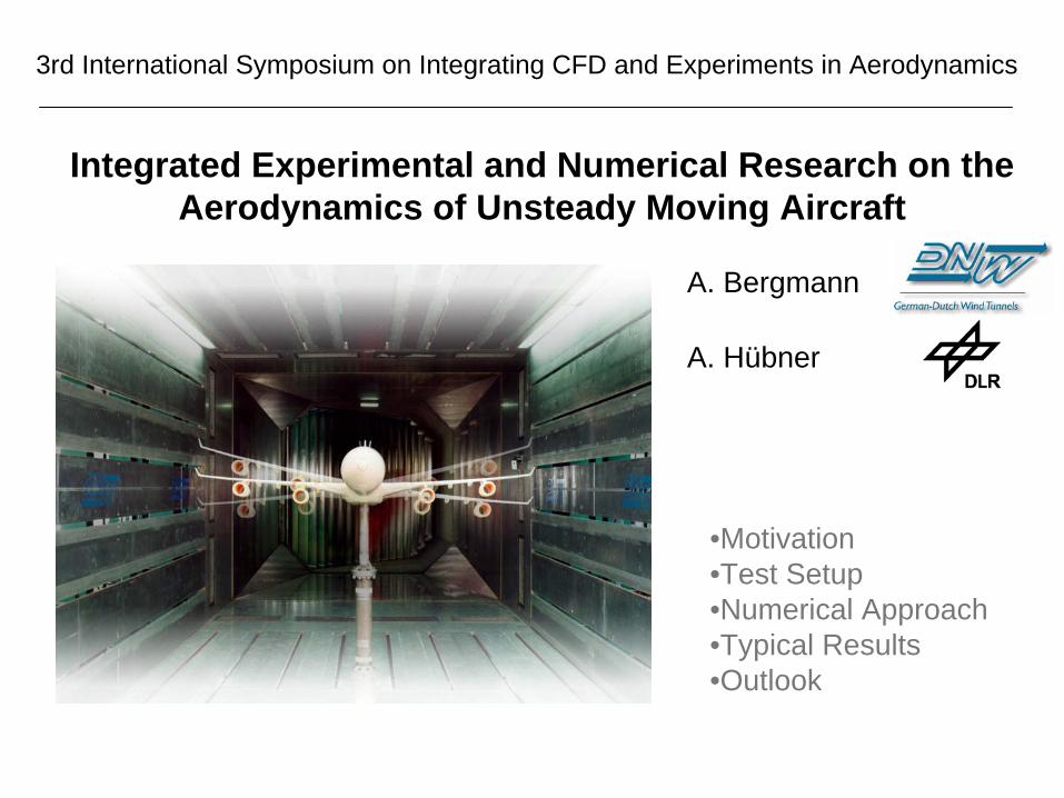
Dynamic Stability Testing of A/C NEEDS vs. CAPABILITIES
Low α (Transport aircraft)
High α (Space Shuttle, Concorde,
Fighter aircraft)
Flow mainly linear, often well known
strong non-linear effects (separation, transition, vortex shedding, etc.)
Analytical prediction of dynamic derivatives
easy (linear potential methods and various approximations often acceptable)
very difficult (highly non-linear, often speculative, approximations risky)
Magnitude of dynamic derivatives small sometimes very large, varying sign
Variation of dynamic derivatives with α
small sometimes very rapid
Effect of dynamic derivatives on flight trajectory and on stability and control
insignificant or at least constant and well-known
sometimes very large, may often be significant.
Situation in the 70ties (Orlik – Rückemann)
Changing interest in dynamic derivatives – high α
vs. low α

21 June 2007Bergmann / Hübner
3rd International Symposium on Integrating CFD and Experiments in AerodynamicsUSAF-Academy
4
Today´s Situation
A380• relative short lever arm of tail unit• larger taper ratio• non-circular cross section
A400M• tail ramp• sponsons• T-tail
BWB• hybrid shape• short lever arms, small damping
21 June 2007Bergmann / Hübner
3rd International Symposium on Integrating CFD and Experiments in AerodynamicsUSAF-Academy
5
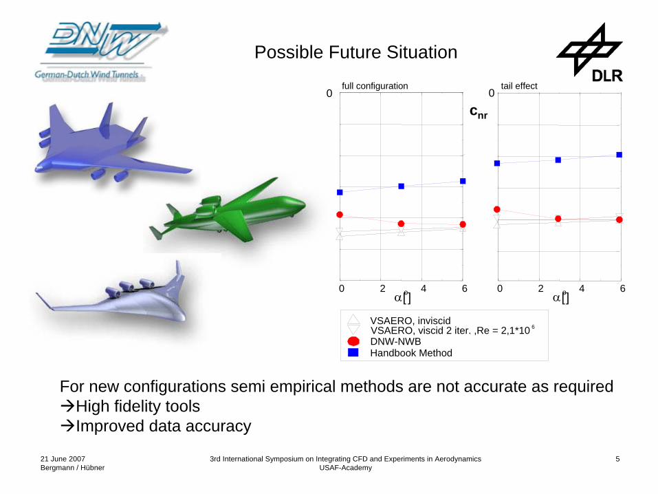
Possible Future Situation
For new configurations semi empirical methods are not accurate as requiredHigh fidelity toolsImproved data accuracy
cnr
6 VSAERO, inviscidVSAERO, viscid 2 iter. ,Re = 2,1*10DNW-NWBHandbook Method
0 2 4 6α[o]
0 2 4 6α[o]
full configuration tail effect0 0

21 June 2007Bergmann / Hübner
3rd International Symposium on Integrating CFD and Experiments in AerodynamicsUSAF-Academy
6
RotaryRotary--BalanceBalance of DNWof DNW--NWBNWB
21 June 2007Bergmann / Hübner
3rd International Symposium on Integrating CFD and Experiments in AerodynamicsUSAF-Academy
7
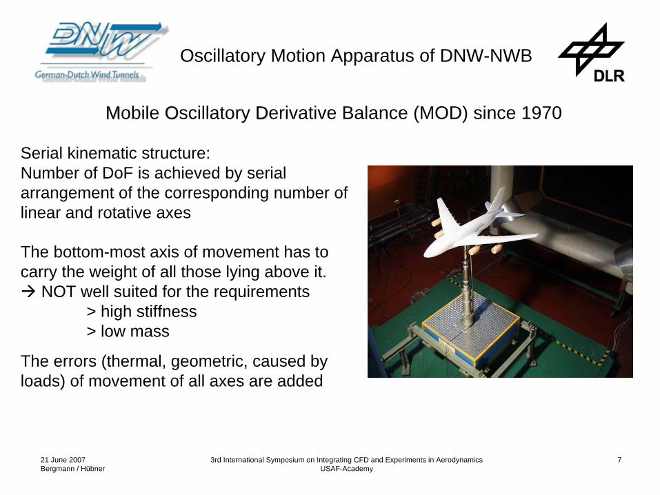
MMobile OOscillatory DDerivative Balance (MOD) since 1970
Serial kinematic structure:Number of DoF is achieved by serial arrangement of the corresponding number of linear and rotative axes
The bottom-most axis of movement has to carry the weight of all those lying above it.
NOT well suited for the requirements> high stiffness> low mass
The errors (thermal, geometric, caused by loads) of movement of all axes are added
Oscillatory Motion Apparatus of DNW-NWB

21 June 2007Bergmann / Hübner
3rd International Symposium on Integrating CFD and Experiments in AerodynamicsUSAF-Academy
8
OOscillatory MMotion SSystem (OMS) since 2000
Parallel kinematic structurebased on Stewart Platform
6 telescope like, driven legs 6DoF
Masses to be moved are smaller
Errors not added
Only forces in axial direction of the legs (largest stiffness)
Hydraulically driven
Available working space smaller compared to machine - size
Advancing the state of the art (1)

21 June 2007Bergmann / Hübner
3rd International Symposium on Integrating CFD and Experiments in AerodynamicsUSAF-Academy
9
Use of the Hexapod System OMS…
…in combination with a gear box in the fuselage as coupled kinematics
Advancing the state of the art (2)

21 June 2007Bergmann / Hübner
3rd International Symposium on Integrating CFD and Experiments in AerodynamicsUSAF-Academy
10
Approach since 2003:
Investigation of an existing prototype of milling machine based on parallel kinematics
goal: develop an optimized system to meet the requirements of W/T model support
Principle of Rod kinematic6 rods with constant lengthrail guides, electically driven
Design and build a W/T dynamic test rig to investigate manoeuvring characteristics of future aircraft
6DOFrepresentative rates / ampl.
Advancing the state of the art (3)
21 June 2007Bergmann / Hübner
3rd International Symposium on Integrating CFD and Experiments in AerodynamicsUSAF-Academy
11
Advancing the state of the art (4), Requirements
6 DoF
Workspace (long., lateral, heave): 1100mm, 300mm, 500mm
Pivoting angles of - 5° to + 5° for rolling, accuracy < 0.005° -15° to + 7° for pitching < 0.01° -10° to +10° for yawing < 0.005°
Near constant and high stiffness all over the workspace
First eigenfrequency > 20 Hz
Max acceleration 2.5 g
Oscillatory Motion of the model in the modesYawing, Pitching, Rolling, (Heave) up to 3 Hz with 5°(60mm) Amplitude
Max payloads Fx / Fy / Fz 1500 / 1000 / 5000 N Mx / My / Mz 500 / 1000 / 600 Nm
21 June 2007Bergmann / Hübner
3rd International Symposium on Integrating CFD and Experiments in AerodynamicsUSAF-Academy
12
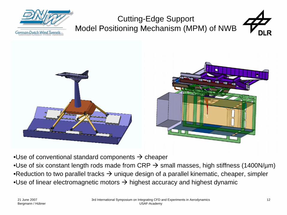
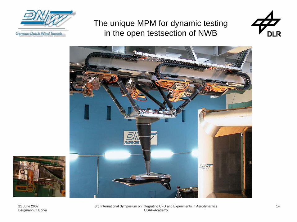
Cutting-Edge Support MModel PPositioning MMechanism (MPM) of NWB
•Use of conventional standard components cheaper•Use of six constant length rods made from CRP small masses, high stiffness (1400N/µm)•Reduction to two parallel tracks unique design of a parallel kinematic, cheaper, simpler•Use of linear electromagnetic motors highest accuracy and highest dynamic

21 June 2007Bergmann / Hübner
3rd International Symposium on Integrating CFD and Experiments in AerodynamicsUSAF-Academy
13
MModel PPositioning MMechanism (MPM)
Max Force: 20,700 NVelocity at Fmax up to 6 m/sec
21 June 2007Bergmann / Hübner
3rd International Symposium on Integrating CFD and Experiments in AerodynamicsUSAF-Academy
14
The unique MPM for dynamic testing in the open testsection of NWB
21 June 2007Bergmann / Hübner
3rd International Symposium on Integrating CFD and Experiments in AerodynamicsUSAF-Academy
15
f [Hz]
Ampl
itude
0 5 10 15 20 25 30 35
10-4
10-3
10-2
10-1OMSMPM
t [s]
Mz
[Nm
]
1 1.2 1.4 1.6 1.8 2-80
-60
-40
-20
0
20
40
60
80
OMSMPM
t [s]
Ψ[°]
1 1.2 1.4 1.6 1.8 2-6
-4
-2
0
2
4
6
OMSMPM
f [Hz]
Am
plitu
de
0 5 10 15 20 25 30 3510-3
10-2
10-1
100OMSMPM
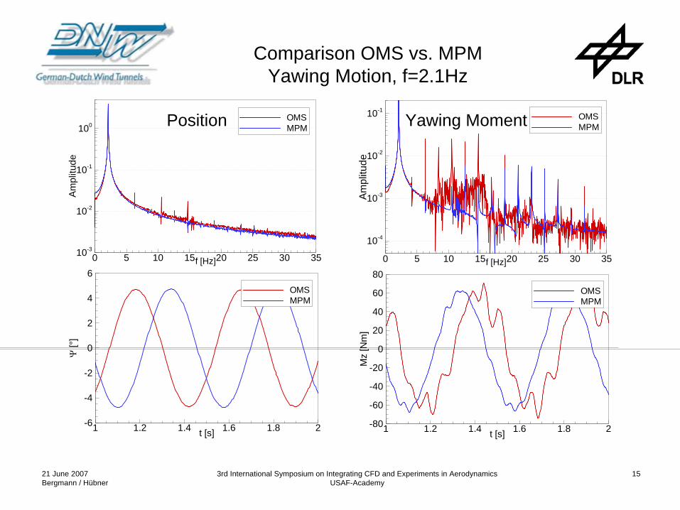
Comparison OMS vs. MPM Yawing Motion, f=2.1Hz
Position Yawing Moment
21 June 2007Bergmann / Hübner
3rd International Symposium on Integrating CFD and Experiments in AerodynamicsUSAF-Academy
16
t [s]
My
[Nm
]
1 1.2 1.4 1.6 1.8 2-150
-100
-50
0
50
100
150OMSMPM
f [Hz]
Am
plitu
de
0 5 10 15 20 25 30 35
10-4
10-3
10-2
10-1OMSMPM
f [Hz]
Am
plitu
de
0 5 10 15 20 25 30 35
10-3
10-2
10-1
100OMSMPM
t [s]
Φ[°
]
1 1.2 1.4 1.6 1.8 2-6
-4
-2
0
2
4
6OMSMPM
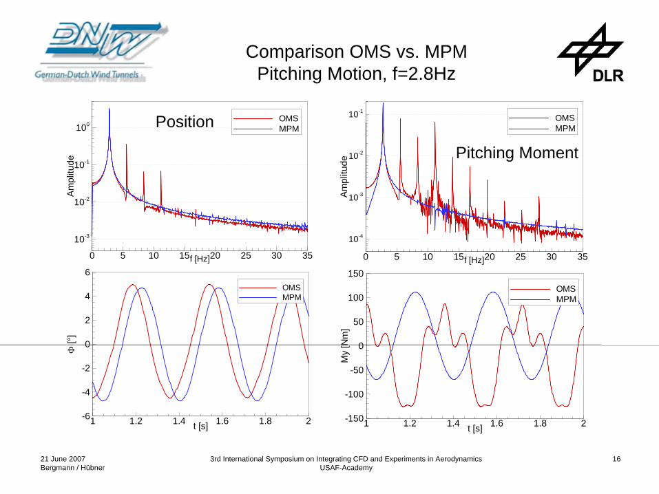
Comparison OMS vs. MPM Pitching Motion, f=2.8Hz
Position
Pitching Moment

21 June 2007Bergmann / Hübner
3rd International Symposium on Integrating CFD and Experiments in AerodynamicsUSAF-Academy
17
unsteady heave osc.Cmα
..unsteady pitching motion
Cmα
+ Cmq
quasi-steady motionCmq
= +
Dynamic Derivatives
Roll Clp Cnp CYp = f (p)
Pitch (CDα
+CDq ) CLα
+CLq Cmα
+Cmq = f (α,q)
Yaw Clr - Clβ
Cnr - Cnβ
CYr - CYβ
= f (β,r)
Heave ocs. CWα
CAα
Cmα
= f (α)
Lateral osc. Clβ
Cnβ
CYβ
= f (β)
.
. . .
. . .
. . .
. .
.
.
.
.
21 June 2007Bergmann / Hübner
3rd International Symposium on Integrating CFD and Experiments in AerodynamicsUSAF-Academy
18
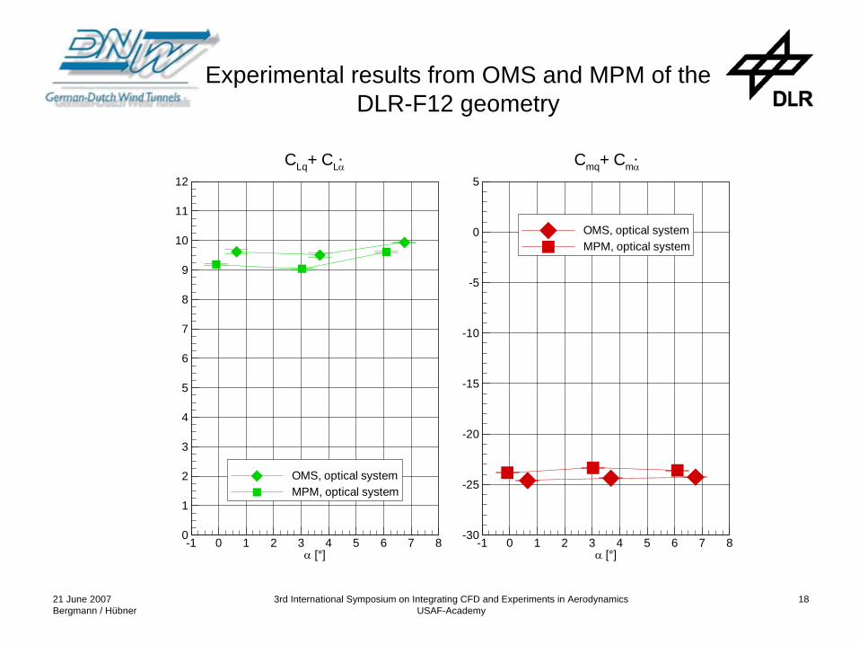
Cmq+ CmαCLq+ CLα..
α [°]-1 0 1 2 3 4 5 6 7 8
0
1
2
3
4
5
6
7
8
9
10
11
12
OMS, optical systemMPM, optical system
α [°]-1 0 1 2 3 4 5 6 7 8
-30
-25
-20
-15
-10
-5
0
5
OMS, optical systemMPM, optical system
Experimental results from OMS and MPM of the DLR-F12 geometry

21 June 2007Bergmann / Hübner
3rd International Symposium on Integrating CFD and Experiments in AerodynamicsUSAF-Academy
19
Cmq+ CmαCLq+ CLα..
α [°]-1 0 1 2 3 4 5 6 7 8
0
1
2
3
4
5
6
7
8
9
10
11
12
MPM, electrical sensorMPM, optical system
α [°]-1 0 1 2 3 4 5 6 7 8
-30
-25
-20
-15
-10
-5
0
5
MPM, electrical sensorMPM, optical system
Impact of diff. position measurement techniques on the derivatives of the pitching motion
21 June 2007Bergmann / Hübner
3rd International Symposium on Integrating CFD and Experiments in AerodynamicsUSAF-Academy
20
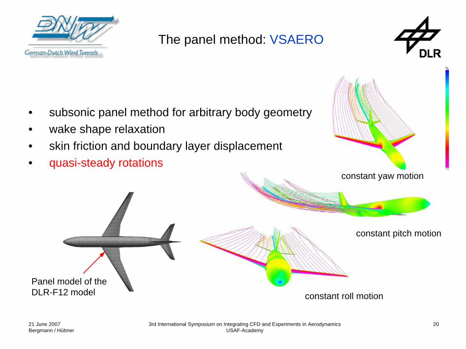
The panel method: VSAERO
• subsonic panel method for arbitrary body geometry• wake shape relaxation• skin friction and boundary layer displacement• quasi-steady rotations
Panel model of the DLR-F12 model constant roll motion
constant pitch motion
constant yaw motion

21 June 2007Bergmann / Hübner
3rd International Symposium on Integrating CFD and Experiments in AerodynamicsUSAF-Academy
21
Hybrid Navier-Stokes Solver DLR TAU-code
• solution of RANS equations for arbitrary moving bodies on unstructured meshes
• independent of grid cell type (hybrid meshes)• various turbulence models• grid adaptation (refinement & de-refinement)• designed for massively parallel computers• validated for increasing number of test cases• routinely used by DLR and Aircraft Industry• quasi steady / unsteady movements
(steady/unsteady flow)
21 June 2007Bergmann / Hübner
3rd International Symposium on Integrating CFD and Experiments in AerodynamicsUSAF-Academy
22
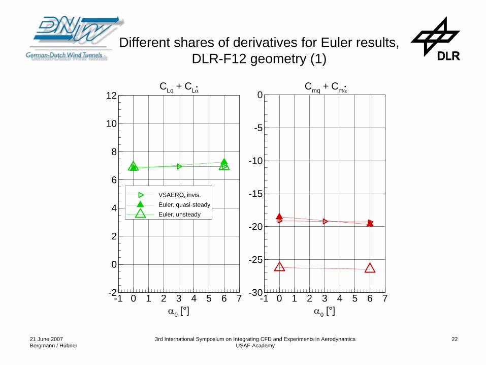
Different shares of derivatives for Euler results, DLR-F12 geometry (1)
α0 [°]-1 0 1 2 3 4 5 6 7-30
-25
-20
-15
-10
-5
0.Cmq + Cmα
α0 [°]-1 0 1 2 3 4 5 6 7-2
0
2
4
6
8
10
12
VSAERO, invis.Euler, quasi-steadyEuler, unsteady
.CLq + CLα
21 June 2007Bergmann / Hübner
3rd International Symposium on Integrating CFD and Experiments in AerodynamicsUSAF-Academy
23
α0 [°]-1 0 1 2 3 4 5 6 7-2
0
2
4
6
8
10
12
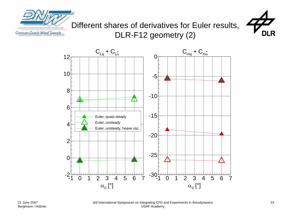
Euler, quasi-steadyEuler, unsteadyEuler, unsteady, heave osc.
.CLq + CLα
α0 [°]-1 0 1 2 3 4 5 6 7-30
-25
-20
-15
-10
-5
0.Cmq + Cmα
Different shares of derivatives for Euler results, DLR-F12 geometry (2)

21 June 2007Bergmann / Hübner
3rd International Symposium on Integrating CFD and Experiments in AerodynamicsUSAF-Academy
24
α0 [°]-1 0 1 2 3 4 5 6 7-2
0
2
4
6
8
10
12
Euler, quasi-steadyEuler, unsteadyEuler, unsteady, heave osc.Euler, quasi + heave osc.
.CLq + CLα
α0 [°]-1 0 1 2 3 4 5 6 7-30
-25
-20
-15
-10
-5
0.Cmq + Cmα
Different shares of derivatives for Euler results, DLR-F12 geometry (3)

21 June 2007Bergmann / Hübner
3rd International Symposium on Integrating CFD and Experiments in AerodynamicsUSAF-Academy
25
Comparison of numerical and experimental results, DLR-F12 geometry
α0 [°]-1 0 1 2 3 4 5 6 7-2
0
2
4
6
8
10
12
DNW-NWB, A/CEuler, unsteadyNa-St., unsteady
.CLq + CLα
α0 [°]-1 0 1 2 3 4 5 6 7-30
-25
-20
-15
-10
-5
0.Cmq + Cmα

21 June 2007Bergmann / Hübner
3rd International Symposium on Integrating CFD and Experiments in AerodynamicsUSAF-Academy
26
t [s]
Δα[°
]
F N[N
]/Am
pl(E
xp)[
N]
My
[Nm
]/Am
pl(E
xp)[
Nm
]
0.3 0.35 0.4 0.45 0.5 0.55 0.6 0.65-5
-4
-3
-2
-1
0
1
2
3
4
5
-1.2
-1.0
-0.8
-0.6
-0.4
-0.2
0.0
0.2
0.4
0.6
0.8
1.0
1.2
-1.2
-1.0
-0.8
-0.6
-0.4
-0.2
0.0
0.2
0.4
0.6
0.8
1.0
1.2
FN, Exp.My, Exp.Δα, Exp.FN, EulerMy, EulerΔα, EulerFN, Na-St.My, Na-St.Δα, Na-St.
Δt
DLR-F12, pitching motion, comparison of experimental and numerical results

21 June 2007Bergmann / Hübner
3rd International Symposium on Integrating CFD and Experiments in AerodynamicsUSAF-Academy
27
phase of FL [°]
CLq
+C
Lα
-178 -177 -176 -175 -174 -173 -172 -171 -170 -1690
4
8
12
16
CLq + CLα
Y = A + B*XA = 2.62 E+2B = 1.46 E+0
R2 = 0.999996
. .
..
determined phase(from calc. and exper.)
Effects of phase error: Derivative of the pitching oscillation

21 June 2007Bergmann / Hübner
3rd International Symposium on Integrating CFD and Experiments in AerodynamicsUSAF-Academy
28
phase of FL [°]
phase of My [°]
CLq
+C
Lα
Cm
q+
Cm
α
-178 -177 -176 -175 -174 -173 -172 -171 -170 -169
-91 -90 -89 -88 -87 -86 -85 -84 -83 -82
0
4
8
12
16
-28
-26
-24
-22
-20
CLq + CLα
Cmq + Cmα
Y = A + B*XA = 2.62 E+2B = 1.46 E+0
R2 = 0.999996
Y = A + B*XA = -7.37 E+1B = -5.79 E-1
R2 = 0.999822
. .
..
determined phase(from calc. and exper.)
Effects of phase error: Derivative of the pitching oscillation
21 June 2007Bergmann / Hübner
3rd International Symposium on Integrating CFD and Experiments in AerodynamicsUSAF-Academy
29
α [°]-1 0 1 2 3 4 5 6 7
-23.0
-22.0
-21.0
-20.0
-19.0
-18.0
-17.0
-16.0
-15.0
-14.0
-13.0
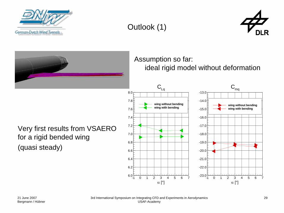
wing without bendingwing with bending
Cmq
α [°]-1 0 1 2 3 4 5 6 7
6.0
6.2
6.4
6.6
6.8
7.0
7.2
7.4
7.6
7.8
8.0
wing without bendingwing with bending
CLq
Outlook (1)
Assumption so far: ideal rigid model without deformation
Very first results from VSAERO for a rigid bended wing (quasi steady)

21 June 2007Bergmann / Hübner
3rd International Symposium on Integrating CFD and Experiments in AerodynamicsUSAF-Academy
30
• Investigation of a new elastic wind tunnel model in 2007• Determination of the unsteady wing shape during the motion• Measurements of the unsteady pressure distribution • Numerical investigations with multidisciplinary codes with coupled
aerodynamic-structural solvers
Outlook (2)
Top Related