


Languages
Pages
Legal


~ PM 8030 Airway Monitor Instructions for Use
- Software 6.n -

Contents
Page
3
,. 4 5
6
Page
Order List ............................................................. 46
Preparation.. ........................................................ Attaching PM 8030 ............................................ 6 Connecting sensor and pressure measuring line. 6 Connecting sensors to anaesthetic machine ........ 7 Connecting 02 sensor capsule.. ......................... 7 Connecting 02 sensor ........................................ 7 Connecting flow sensor and pressure measuring line ..................................................... 0 Connecting temperature sensor.. ........................ 8 Connecting other machines ................................ 8 Additional earth connection ................................. 9 Connecting to power supply ............................... 9 Checking mains failure alarm, carrying out self-test ............................................................... 10
Appendix ............................................................. .48 Flow measurement measuring principle and signal processing ........................................ 48 Definition of PEEP and plateau pressure ........... .48 02 measurement. measuring principle and signal processing ........................................ 49 Anaesthetic agent measurement measuring principle.. ........................................... 49 Explanation of terms used ................................. .50
For Your Safety and That of Your Patients ....
Intended Use . . . . . . . . . . . . . . . . . . . . . . . . . . . . . . . . . . . . . . . . . . . . Brief description . . . . . . . . . . . . . . . . . . . . . . . . ..~...............
......
.....
Calibration ............................................................ 11 Calibrating 02 sensor ......................................... 1 1 02 sensor . checking linearity ............................. 13 Calibrating flow sensor ............................ . ......... .13 Cleaning flow sensor .......................................... 14 Calibrating anaesthetic agent sensor.. ................ .15
Operation .............................................................. 16 Carrying out function check ............................... .76 Selecting anaesthetic agent ............................... .18 Setting limit values .............................................. 18 Displaying measured values ............................... .23 Alarms ................................................................ 26 Communication by PM 8030 with other Driger machines ................................................. 27 Independent documentation ............................... 28 Shut-down .......................................................... 28
Fault - Cause - Remedy ...................................... 29
Care ....................................................................... 33 Stripping down ...................................................... 33 Disinfecting/cleaoing/sterilizing .............................. 34
Checking Function .............................................. 36
Maintenance Intervals ........................................ 37
Configuration.. ..................................................... 38 Setting language of display texts ........................... 38 Interface protocol for PM 8010 or PM 8020 ......... .39 interface protocol for printer .................................. 40 Switching on/off A-VaplAW.Temp. sensors ........... 41
What’s What ................... . .................................... 42
Technical Data ..................................................... 44
Index ...................................................................... 51
2
Al

For Your Safety and That of Your Patients
,For correci and eifec:I/e use of the apparaius and io avoid ,?arards it is essemiai :o :ead the foNow;ng zcommenda- :ions and i0 Xf aCCOrC~~~&~‘:
Strict/y follow the instructions for use
Any use oi the apparas xquires full undersanding and srr;cr observation of ;i;ese ~nstruclions. The aoosraius is only to be used for purooses specified here.
Maintenance
The apparatus must 5e inspected and serviced by experts at regular 6 month interals (and a record kept). We recommend obtaii;ing a service contrac: with
Lwgerservice. Repairs and general werhaul of the apparaius may only be carried out by DrtigerSer/ice. Only original Drager s&we parts may be used for mainte-
nance. Observe chapter “Mainrenance intervals”.
Power connectfon
The apparatus is on/y :o be used in rooms w;th mains /mwer
supply installations complying with national safety standards (such as in F. Ft. of Germany: VDE 0107). The requirements laid down in /EC 60 1, i “Safety of Medical Eiectrical Equipment” are applicable for electrically po wered ‘equipment.
Not for “se in areas of explosion hazard
This apparatus is neither approved nor certified for use in areas where combusiible or explosive gas mixtures are likely to occur.
Connection with other electrical equipment
Nectrical connections io equipment which is not listed in these instructions for use should only be made following consultations with the respective manufacturers or an e.Xpert.
Liability for proper function or damage
The liability for the proper function of The apparatus is irrevocably transferred to the owner zi operator to the extent that the apparatus Is serviced or re.oared by personnel not employed or authorized by DriigerSa,vice or if the apparatus is used in a manner not conforming :o !!s intended use.
Dragenverk Akt;engesellschaft cannci be held responsible for damage caused by non-compliafice with the recommendations given above. The warranty and /iability provis;ons of the terms of sake and ce!ivery of DrBgerwerk Aktiengesellschaft are likewise noi nodified by the
recommendations given above.
Dragenverk Aktiengesellschaft
3
44

Intended Use
Measuring and rxziioring ventilation parameters and the concentration of xaesthetic agents during anaesthesia.
Measuring:
Airway pressure Zzw Peak, Plateau. PEEP, Pmean
expiratory minute :oiume i/E, tidal volume VT, breathing frequency,
inspiratory oxygen concentration FiO2
inspiratory airway :emperature
Concentration in i:ash gas of halothane, enflurane. isoflurane
Monitoring:
Airway pressure paw
lnspiratory oxygen concentration FiO2
Expiratory minute ,volume i/E
lnspiratory airr+ remperature
Concentration oi anaesthetic agent in fresh gas
RS 232 C-lnteriace:
For exchanging dara with the PM 8010 Patient Monitor (software 3.2) or :he PM 8020 Data Manager or for transferring data IO a PC or a printer.
Monitorbus-lntetiace:
To start measurir; operations by PM 8030 or other monitors centrally irom the Ventilog 2 anaesthetic ventilator.
Do not use with flammable gases or flammable anaesthetic agents.

Brief description
- -- --, ,,,s*.,
r,-,
.3 7 (J .--
- -.__ _.~__
The display fields for measured values are on the left:
02 concentration
Lower limit value 02
Anaesthetic agent concentration
Minute volume or tidal volume, can be selected with button m
Airway pressure or tidal volume as strip display, can be selected with button z
The right-hand display field shows the values:
PEEP, Plateau, Peak
or these can be selected with button ,@j
Pmean, aiway temperature, breathing frequency
The menu guide and the alarm displays are shown in the right-hand display field.
The menu content can be recalled using the menu buttons:
Q select limit values
@ calibrate sensors
(ZJ select anaesthetic agent
With selector knob:
to select or to adjust = turn; confirm = press
menu contents are selected, limit values set and special warning messages confirmed.
Other function buttons:
‘-3 Change operating mode: measuring or standby mode CJ A
:& suppress warning tone for 2 minutes
‘-3 n. ,: display stored warning messages

Preparation
Attaching PM 8030
by lxhing mechanism to base for Drager medical equipment
0
1
2
or
l
l
Remove the two feet.
Tilt PM 8030 forward at an angle of 45’, insert front
latches into the slots on the base.
Cower PM 8030. inserting the rear latches into the ream dots and secure at the back with knurled screwy.
Place on an even surface such as a monitor rack,
Fix PM 8030 securely.
Connecting sensor and pressure measuring line
0 Use sterile or disinfected sensors.
At the back
1 Connect 02 sensor plug.
2 Connect temperature sensor plug.
3 Push hose of pressure measuring line firmly onto spigot.
4 connect flow sen?.or plug.
5 Connect anaesthetic agent sensor plug.
6
-@0043 0 0

Preparation
Connecting sensors to anaesthetic machine
In brief:
02 sensor
Coupling for pressure measuring line
Flow sensor
Temperature sensor
The anaesthetic agenr sensor is permanently mounted in the fresh gas supply of the anaesthetic machine. which must only be done by IXgerService.
Connecting 02 sensor capsule
1 Unscrew cap from sensor housing.
l Remove new sensor capsule from packaging, or use disinfected sensor capsule.
2 Place capsule in housing - ring-shaped conductor track onto contacts in housing.
1 Tighten screw cap by hand.
Connecting 02 sensor
with cap M 21 462
plug adapter M 27 964
condenser, if a great deal of condensation is expected M 27 666
Unscrew the nut on the inspiratory valve.
Replace the sight giass with cap. Re-fit the nut.
Firmly screw the lower part of plqadapter into cap by hand.
Push 02 sensor onto cap as far as it will go,

Preparation
Connecting flow sensor and pressure measuring line
with measuring connection M 28 833
0
1
2
1
3
Screw flow sensor into housing.
Unscrew expiratory valve.
Screw the measuring connection on with the flow sensor in place.
Screw expiratory valve back.
Push plug of pressure measuring line into coupling - as far as it will go. Tilt hose upwards so that condensate can flow downwards.
Connecting temperature sensor
Adapter and accessories:
Y-piece M 30 543
Hose clip (set of 10) 84 04 047
Push temperature sensor into hole on the Y-piece as far as it will go. After replacing the Y-piece, align sensor vertically so that condensate will not be able to get into it.
Attach sensor cable to inspiratoty hose with hose clips.
A3
Connecting other machines
via RS 232 C-Interface
. PM 8010 Patient Monitor with data cable “PM 8010” 85 00 337
. PM 8020 Data Manager with data cable “PM 8020”
Printer e.g.: Desk Jet Printer (Hewlett Packard) Think Jet Printer (Hewlett Packard) PA 565 (NEC) with data cable
0 Connect and secure plug to both machines.

E.g. for remote switching on of PM 8030 from Standby or switching on anaesthetic ventilator
or
for muting Drsger equipment.
with Monitorbus cable 0.45 m M 30893
Preparation
via Monitorbwlnterface
1
1 Connect plug to both machines and secure with screwdriver.
2 Another machine can be connected with the second
connection.
Additional earth connection
e.g. for cardiac operations
l Attach one end of the earth cable to the potential
equalisation, pin at the back of the machine.
l Connect the other end to a potential equalisation poinr
in the room.
Connecting to power supply
PM 8030 can be operated on mains voltages from 100 V
to 240 V.
l Connect monitor to mains power supply.
r
9
Alo

Preparation
Checking mains failure alarm, carrying out self-test
before first operation and after long periods of storage.
1 Switch on mains power supply at the back.
After about 10 seconds:
2
1
0
2
1
0
Press >Standby< button; green LED goes out = measuring mode.
Switch off mains:
A continuous tone commences, volume remains constant for at least 10 seconds = mains failure alarm is functional. Otherwise: charge NiCd battery.
Press >Standby< button; the continuous tone ceases.
Switch mains power back on:
The monitor now carries out a self-test. All LEDs and display elements are lit; a single tone sounds. Software and language versions are displayed. The internal program memories are tested. The alarms for monitoring are checked.
The self-test is completed in about 30 seconds.
Charging NiCd battery
If, when the mains failure alarm is being checked, the volume decreases after 10 seconds:
Leave machine connected to the mains power supply and switched on for 24 hours.
0 Check mains failure alarm again.
10

Calibration
On request by PM 8030
after switching on
message >sensor not ready to measure<
or
when calibrating during operation:
1 Press calibration button
2 Display: Sensor calibration 02 flow A-Vap
3 Select desired ?.ens.or = turn knob and confirm = press knob.
For further information, refer to:
Calibrating 02 sensor, see below
Calibrating flow sensor. page 13.
Calibrating anaesthetic agent sensor, page 15
Calibrating 02 sensor
after sensor has been replaced (15 minutes warming-up time).
after 24 hours.
after 1 month carry out linearity check.
For use mainly with 02 concentrations up to 60% by vol.: calibrate with air
For use with 02 concentrations up to 100% by vol. and for linearity checks: calibrate with 02
Calibration with air
l Remove 02 sensor and expose to ambient air for 2
minutes.
When requested by machine after switch on
Or
1 Press calibration button and select 02 sensor.
2 Display: Calib. 02 sensor? 21% 100% no
With the 02 semor in ambient air
3 Select >21%< in menu and confirm.

Calibration
1 Display: Oz calibration at 21 vol. %
2 Display for 02 concentration:
CAL
After about 30 seconds, but no longer than 3 1/2minutes
1 Display: 02 sensor calib. completed
0 Replace 02 sensor on cap
Calibration with Oz
0 Remove 02 sensor and fit test adapter 68 01 349 to
sensor.
0 Flush the 02 sensor with a flow of about 1 L/min for
about 2 minutes.
When requested by the machine after switching on
or
Press calibration button and select 02 sensor.
Display: Calib. Oz sensor? m 100% no
Continue flushing with OZ.
Select >lOO%< in menu and confirm.
Display: 02 calibration at 100 vol. %
Display for 02 concentration CAL
After about 30 seconds but no longer than 3 l/2 minutes:
2 Display: 02 sensor calib. completed
Calibration has been completed.
0 Switch off 02 flow, removk test adapter and replace
02 sensor on cap.
12
= F
F t
02 ca. 1 Llmin 1 I
A 13

Calibration
Checking linearity
to be carried out monthly
First calibration with OZ. page 12, then:
l Expose sensor to ambienr air for about 2 minutes.
1 02 concentration display: 21 vol. % 02 2 3% by vci.
l Replace 02 sensor on cap
If the display is outside the range 18 to 24% 02 by vol.,
the sensor capsule is faulty.
0 Replace capsule. page 7 and calibrate, page 11.
Calibrating flow sensor
when sensor has been replaced
- after 24 hours of operation
0 Unscrew measuring connection and remove flow sensor.
l With flow sensor in horizontal position - connector pointing downwards seal both openings in the ambient air preferably using thumb and middle finger.
.After a request by the monitor when switching on
Or
1 Press calibration button and select flow sensor.
2 Display: Calib. flow sensor? yes no cleaning
With sealed Sensor
3 Select >yes< and confirm
2 Display: Flow sensor calibration
Calibration
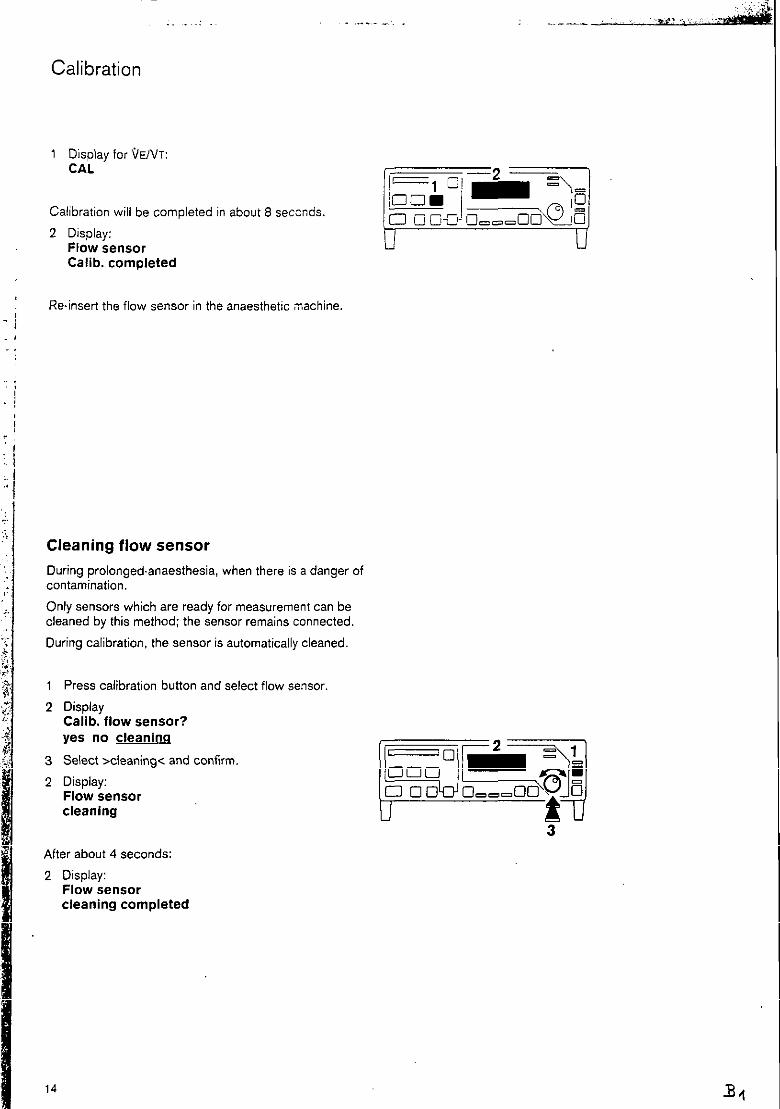
1 Display for VENT: CAL
Calibration will be completed in about 8 seccnds.
2 Disolav: Fldw kensor Calib. completed
Re-insert the flow sensor in the anaesthetic ;nachine,
Cleaning flow sensor
During profonged.anaesthesia, when there is a danger of contamination.
Only sensors which are ready for measurement can be cleaned by this method; the sensor remains connected.
During calibration, the sensor is automatically cleaned
Press calibration button and select flow ~enspr
Display Callb. flow sensor? yes no cleaniw
Select xleaning< and confirm.
Display: Flow sensor cleaning
After about 4 seconds:
2 Display: Flow sensor cleaning completed
14

Calibration
Calibrating anaesthetic agent sensor
when sensor has been replaced
every 24 hours
Allow 3 minutes warming-up time after switching on the
machine.
On anaesthetic machine
l Set anaesthetic vaporiser to 0 (zero point stop button engaged), otherwise faulty calibration will occur. Set 02 flow of about 10 Llmin on flowmeter block or on blender.
l Flush anaesthetic agent seneor for at least 10 seconds.
Do not use 02 flush for flushing.
After switching on and after request by machine
Or
1
2
3
2
Press calibration button and select A-Vap sensor.
Display: Calib. A-Vap sensor?
Ye II0
Select >yes< and confirm.
Display: A-Vap sensor flushed with Oz/air?
Continue with anaesthetic vaporiser at 0 and 02 flow of about 10 Umin.
3 Confirm = press knob.
2 Display: A-Vap sensor calib.
4 A-Vap display CAL
Calibration is completed in about 0 seconds
2 Display: A-Vap sensor calib. completed
If there is a faulty sensor or cable:
2 Display: A-Vap sensor not ready to measure
15
32

Operation
Carrying out function check
Immediately before daily use as described in the checklist
on the anaesthetic machine
Monitor self-test
Switch on mains power supply at the back.
The monitor carries out a self-test: The internal programme memories are tested. The software and language versions are displayed. All LEDs and display elements are lit; a single tone
sounds.
Display: Drtiger PM 8030
The alarms for monitoring are tested.
The self-test is completed after about 30 seconds.
For operation with Monitorbus
0 Switch ventilator to IPPV:
1 The green LED goes out, PM 8030 is in measuring
mode.
Checking 02 measurement
2
0
3
l
Press >Standby< button, green LED goes out = measuring mode
Remove 02 sensor from cap and expose to ambient air for at least 2 minutes.
Display: 21 vol. % 02
Replace 02 sensor on cap.
16

Operation
Checking pressure measurement
1 Kink pressure measurement hose near the coupling and
2 Squeeze hose :o close it:
3 A value greater than 0 mbar is displayed.
0 Release hose:
3 Value 0 mbar is displayed
Checking flow measurement
On anaesthetic machine:
. Switch to spontaneous breathing/manual ventilation,
keep Y-piece sealed and fill breathing bag with the 02 flush.
On PM 8030:
4 Select VT with >\idvT< button.
l Squeeze out breathing bag with Y-piece closed
5 A value greater than 0 L is displayed.
PM 8030 is ready for use.
17
3+

Operation
Selecting anaesthetic agent
After switching on and after request by machine
Display: Select A-Vap w Enf. Iso. none
Select = turn knob and confirm = press knob.
Selecting another anaesthetic agent:
3 Press >A-Vap< button:
1 Menu selection is indicated.
2 Select anaesthetic agent and confirm
Setting limit values
for monitoring parameters
4
5
or
lnspiratory 02 concentration FiO:, % by vol.
Airway pressure Paw mbar
Expiratory minute volume OE Llmin
Anaesthetic agent concentration A-Vap % by vol.
Press >limit values< button.
The menu selection for limit values is displayed: Limit values <IPPV> MODE 02 VE Paw A-Vap
Limit values cMANISP> MODE 02 VE Paw A-Vap
<IPPV> is the display for complete limit value monitoring
<MAN/SP> is the display for reduced limit value
monitoring, page 22.

Operation
Continue menu selection:
I To select monitoring parameters = turn knob and confirm = press knob.
Display. e.g.: FiOz I vol. %
21 Exit ---
Lower l$value is on the left; upper limit value is on the
right
1 Select limit value and confirm,
Example given: lower limit value: 21% by vol. upper limit value: --. = off
The dashes under limit value flash = request to set
limit value.
then
1 Set limit value and confirm, the dashes under limit value cease flashing.
I Exit menu: Select >Exit< and confirm.
The next parameter can now be selected
l Press another button = Complete setiing of limit values.
Or
l Wait for about 15 seconds = time out.
Factory Setting
= Standard limit values
lower limit upper limit
value value
Fi02 20 . .
P&V 0 40
Min. vol. (OE) 3 12
A-VaplHal 0 2
A-VaplEnf 0 2
A-Vapllso 0 2
AW-Temp -- 40
Setting range
18 to 100
oto 98
0 to 40
oto 9
oto 9
oto 9
fixed setting
The lower and upper limit values cannot overlap
The upper limit value for FiOz and the lower limit value for Paw can be switched off (-- to adjust).
For Paw the minimum separation between lower and upper limit value is 5 mbar.

Operation
Setting 02 limit value
Recommendation:
For 02 concentrations lower than 50% by vol.: lower limit value 5% by vol. lower than the actual 02 concentration.
Where air is applied post-operatively: set lower limit value to 20% by vol.
For 02 concentrations greater than 50% by vol.: lower limit value 10 % by vol. lower than the actual 02 concentration.
~Depending on clinical indications, set or switch off upper limit value.
Setting Paw limit value
Set lower limit value about 8 mbar below plateau pressure.
Where there is no pleateau pressure, set at about 8 mbar below peak pressure.
The lower limit value may be switched off.
Set the upper limit value about 10 mbar above peak pfeSWie.
Setting minute volume (GE) limit values
Recommendation:
Set lower limit value 20% lower than minute volume
Set upper limit value about 20% higher than minute volume
20

Operation
Setting A-Vap limit values
Using the graph, determine the limit values depending on the sening of the anaesthetic vaporiser. The upper limit values are based on the maximum permissible ,vaiues which must not be exceeded. The lower limit value may be set even lower when necessary for clinical reasons.
Vertical axis:
Setting of limit values (0 to 6% by vol.)
/r upper limit value
I/ lower limit value
Horizontal axis:
Concentrations set on anaesthetic vaporiser (0 to 5% by vol.)
Example:
The anaesthetic vaporiser was set at 1.4% by vol.: the intersection with the lower line projected to the left shows the lower limit value Y:
about 0.7% by voi
The intersection with the upper line projected to the left shows the upper limit value /f:
about 2.1% by vol.
Rule of thumb:
lower limit value Y = set value - 50%
upper limit value/f = set value + 50%, max. 6% by vol
21
38

Operation
Limit values - reduced monitoring
For operating conditions such as manual ventilation or spontaneous breathing, monitoring can be reduced to
the parameters
A-Vap with upper limit value
02 with lower limit value
Paw with upper limit value
thus preventing alarms which are not required.
Press z-limit values< button.
Display:
Limit values <IPPV>
Mode 02 VE Paw A-Vap
Select >Mode< and confirm.
Display:
MODE <IPPV>
MANISP IPPV default
Select >MANISPc and confirm.
Display:
limit values
MANISP active = reduced monitoring
Activating all limit values
Set, as described above, but
3 Select >IPPV< and confirm.
2 Display:
Limit values
IPPV active
All limit values are effective at the set values
Selecting default limit values
Set. as described above, but
3 Select >&fault< and confirm.
2 Display:
Limit values
default active
These default limit values are set by the manufacturer and
apply after each restart (table. page 19).
22
33

Operation
Displaying measured values
02 concentration:
1 Display: xxx VOI. %
2 Display of lower limit value:
xx
Anaesthetic agent concentration A-Vap:
3 Display: x,x vol. %
4 Anaesthetic agent selected is shown by the particular LED being lit.
After a cold start, allow a warming-up time of about 3 minutes. No calibration or measurement is possible during this period; dashes are shown in the measured value display, and monitoring is not taking place.
Tidal volume VT or minute volume VE:
5 Display: VTX,XXL
Or
VE XX, X Umin
Selecting other measured values:
6 Press >kA’T< button.

Operation
Analogue values Paw or tidal volume VT:
1 Strip display (Paw mbar) The limit values are displayed brightly
or
Strip display (VT L)
Change display:
2 Press >k,w/‘/T< button.
Strip display can be used for leak test for anaesthetic machine or ventilation.
PEEP, Plat, Peak:
3 Display (mbar): PEEP Plat.’ Peak xx xx xx
Mean pressure, Insp. airway temperature, frequency:
3 Display (mbar, “C, bpm) Pmean AW-Temp Freq. xx xx xx
Change display:
4 Press selector button
If the fixed upper limit value is exceeded (40°C). the temperature measured value flashes.
Where the temperature censor has been disconnected, airway pressure Paw dependent on time is displayed, instead of temperature.
This display can also be used for leak testing.
If dashes (-) appear below PEEP and Plat.. the Row sensor is not ready for measurement. If dashes appear below Plat. in the operating mode MANISPON, there is no plateau pressure.
24

Operation
Alarms All alarms are coded according to their importance and priority and are distinguished optically/acoustically, and displayed accordingly.
Warning messages are given priority in the text
display: the red (lower) LED flashes together with a sound sequence at 2.5 second intervals.
Caution messages: the yellow (upper) LED flashes
together with a sound sequence at 30 second intervals.
Advisory messages: the yellow (upper) LED is lit
together with a single tone.
If there is an alarm, the appropriate warning or caution message is indicated in the upper line of the display. The lower line shows the approptiate measured value, the upper and lower limit values to the right and to the left respectively. Any limit value which has been exceeded can be changed directly with the selector knob (to set and to confirm).
During warning messages for 02 concentration, anaesthetic agent concentration or expiratory minute volume VE, the appropriate displays flash. During warning messages for airway pressure, the appropriate limit value segment flashes in the strip display.
Alarms, their causes and remedies are listed in the table on page 29.
Displaying the last warning message
The last warning message given is stored and can be displayed later for evaluating the alarm. Messages without warning characteristics, such as advisory messages, are not stored.
1 If the symbol is lit. this indicates a warning message which has been stored but not yet displayed.
2 Press button; this last warning message is displayed.
Ending display of the last warning message:
2 Press button again, the symbol disappears.

Operation
Acknowledging advisory messages
With advisory messages. such as for a faulty sensor. the display can be cleared for measured values:
0 Confirm = the advisory message disappears: the yellow LED goes out.
If the error has not been rectified. the advisory message will reappear after a set period.
Suppressing alarm tone
Press button.
The symbol > 0 < is lit; the alarm tone is switched off for 2 minutes. During this period, any new alarms are indicated by a single tone sequence.
The red,or yellow LED continues to flash: the text remains. as well as the flashing displays.
with connected Monitorbus:
0 Other Drager equipment which is connected is automatically muted. The sound can also be switched off on the Drsger equipment which is connected.
Switching on alarm tone again:
1 Press button again.
2 Symbol disappears.
Setting alarm tone volume
4
5
only during Standby.
Keep button pressed: the alarm tone sequence sounds after about 2 seconds.
Turn rotary knob: clockwise = louder anti-clockwise = quieter confirming set volume: press knob.
After switching off and then on again, the normal volume will apply.
26
B 13

Operation
Communication by PM 8030 with other DrSger machines
With the ivlonitorbus
e.g. remote switch is activated to switch PM 6030 on from Standby, after start of the anaesthetic ventilator Or
ior muting the other Drgger machines.
With the RS-232 Interface
For the transfer of warning, caution and advisory messages: of measured values, for the combination of function “Switching on and 2 minute suppression of acoustic alarms” and for remote switching on of other Dreger machines.
Communication with the PM 6010 Patient Monitor (software 3.2): measured values and warnings are transferred according to the MEDIBUS format (baudrate of 1200 bit/s)
Communication with the PM 6020 Data Manager: measured values, warnings and real time curves of flow and pressure are transferred according to the MEDIBUS format (baudrate of 19200 bit/s)
- Communication with a serial printer: measured values and warnings are issued at pre-set time intervals as ASCll-code
Printer setting:
Paper format DIN A411 1”
Page length 66 lines
Page width 80 characters
6 databits, 1 stopbit
non parity, Baudrate
optimum 9600 Bit/s
(1200...19200 Bit/s)

Operation
Independent documentation For the preparation of lists on a printer with serial interface. By changing’from Standby to operation, the documents mav be minted out at ore-set time intervals. The first page hab a protocol h&ding for the entry of patient data. When the anaesthetic agent is changed, a new page must be started.
Example of documentation on a printer:
PM 8636 Documentation Date :_________ Page : I
Name :______________ Prmame :_____________ RF= I ______
A maximum of three simultaneous warning messages can be printed out on one line, i.e. the three most important messages in order of priority. If a new warning is added or deleted, the new warning is printed out according to its priority. The print-out of this warning line is independent of the pre-set time and in addition triggers the print-out of a measured value line. The procedure for caution messages is identical to that of warning messages. Advisory messages are not logged.
Shut-Down
1 Press buttq green LED lights.
2 Disconnect from mains power supply.
0 Remove 02 sensor from cap and expose to the ambient air.
I
I 28

Fault - Cause - Remedy
)iscon.lApnoea pressure 4PNOEA PRESSURE)
‘aw high ‘AW fl
.pnoea volume IPNOEA VOL)
iO2 low :I02 Ifl
lalothane high IAP HAL A)
nflurane high (AP ENF /f,
oflurane high ‘AP IS0 fi
M 8030 fault xxx ‘MB030 INOP)
Cause
Insufficient fresh gas supply Procure adequate fresh gas supply
Mean pressure Pmean smaller than -2 mbar
Airway pressure Paw smaller than -7 mbar
Insufficient fresh gas supply Procure adequate fresh gas supply
Breathing or ventilation has stopped
Leak in hose system Check hose system
Upper limit value for airway pressure has been exceeded,
Kink in ventilation hose, stenosis Check hose system on anaesthetic machine
Pressure limit set too high Adjust pressure limit on anaesthetic machine
Overpressure valve switched off Switch on pressure limit on anaesthetic machine
Breathing or ventilation has stopped. No volume expired during 15 seconds
Insufficient fresh gas supply
Tube blocked/kinked
Leak in hose system
Check ventilator
Procure adequate fresh gas supply
Check hose system
The inspiratory 02 concentration is below the lower limit value
Check 02 supply. check setting of flowmeter on blender
The appropriate anaesthetic agent concentration in the fresh gas is
higher than the upper limit value
Check setting on anaesthetic
vaporiser
Incorrect anaesthetic agent has been selected
Internal hardware fault with error number Machine is not ready for operation
Call DrlgerService, give error number
* Messages in parenthesis are displayed, or printed on the peripheral machines PM 8020 and PM 8010. Or on a PC or on a printer.
29
c2

Fault - Cause - Remedy
lessage
:aution messages
lin. vol. low IMV Jf)
alothane low ‘AP HAL J/j
nflurane low ‘AP ENF if)
oflurane low ‘AP IS0 J/-)
Cause
Lower limit value for minute volume
has been crossed
Tube blocked/kinked
Leak in breathing system
Loss of volume through pressure limitation
Lung compliance has been reduced
Flow sensor not calibrated, or faulty
The appropriate anaesthetic agent concentration in the fresh gas
is lower than the lower limit value
Incorrect anaesthetic agent has been selected
Remedy
Check tube
Seal breathing system.
Correct ventilation parameters
Calibrate flow sensor, page 13; replace if required
Check setting and filling level of anaesthetic vaporiser
02 high ‘102 fT)
Oz.flush used, the inspiratory 02 concentration is above the
upper limit value
Check 02 setting on the
flowmeter block or on the blender
in. vol. high .MV /r)
ul/-Temp. high W-Temp /‘T)
Upper limit value for the minute volume has been exceeded
Flow sewor not calibrated or faulty
The inspiratory breathing gas temperature is above 40°C
Calibrate sensor, page 13 replace if required
Switch off humidifier. When temperature has dropped to
about 37°C set low heating level
neck RS 232 Fault in data connection or cable Check cable
Fault in connected machine Check machine
c3
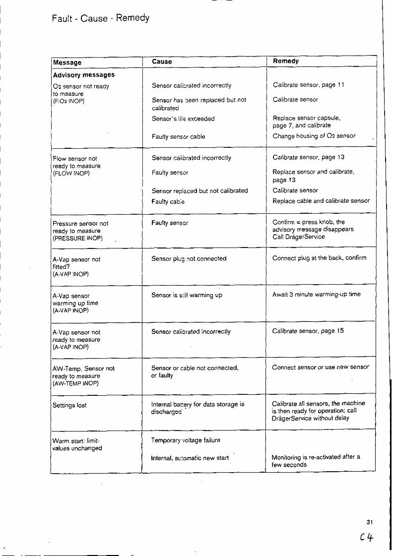
Fault - Cause - Remedy
02 sensor not ready IO measure (FiOz INOP)
Flow sensor not ready to measure (FLOW INOP)
A-Vap sensor not fitted? (A-VAP INOP)
A-Vap sensor warming up time (A-VAP INOP) I--- A-Vap sensor not ready to measure (A-vAP INOP)
AW.Temp. Sensor not ready to measure (AW-TEMP INOP)
Settings lost
Cause
Sensor caii’xated incorrectly
Sensor has been replaced but not calibrated
Sensor’s !iie exceeded
Faulty sensor cable
Sensor caiibrated incorrectly
Faulty sensor
Sensor repiaced but not calibrated
Faulty cabie
Faulty sensor
Sensor plug not connected
Sensor is siill warming up
Sensor caliorated incorrectly
Sensor or cable not connected, or faulty
Internal banFry for data storage is discharged
Temporary -voltage failure
Internal. au:omatic new start
Remedy
Calibrate sensor, page 11
Calibrate sensor
Replace sensor capsule, page 7, and calibrate
Change housing of 02 tensor
Calibrate sensor, page 13
Replace sensor and calibrate,
page 13
Calibrate sensor
Replace cable and calibrate sensor
Confirm = press knob, the advisory message disappears Call DrigerService
Connect plug at the back, confirm
Await 3 minute warming-up time
Calibrate sensor, page 15
Connect sensor or use new sensor
Calibrate all sensors. the machine is then ready for operation: Call Dr~gerService without delay
Monitoring is reactivated after a few seconds
31
c4

Fault - Cause - Remedy
Additional advisory messages
1 Message
ICalib. flow sensor? / (CAL16 FLOW?)
Callb. 02 sensor? (CALIB FlOz?)
Calib. A-Vap sensor? , (CALIB A-VAP?)
Standby (PM8030 STBY)
Limit values Default active
Limit values IPPV active
MAN/SP active
(MAN~P 0 MODE)
-i-
Request to calibrate after switching on machine
Machine is ready for operation Monitoring is switched off
Default limit values selected
Limit values for automatic ventilation selected
Limit values for manual ventilation or spontaneous breathing selected
lower limit value minute volume off upper limit value minute volume off lower limit value Paw off lower limit value A-Vap off upper limit value 02 off
C5
Care
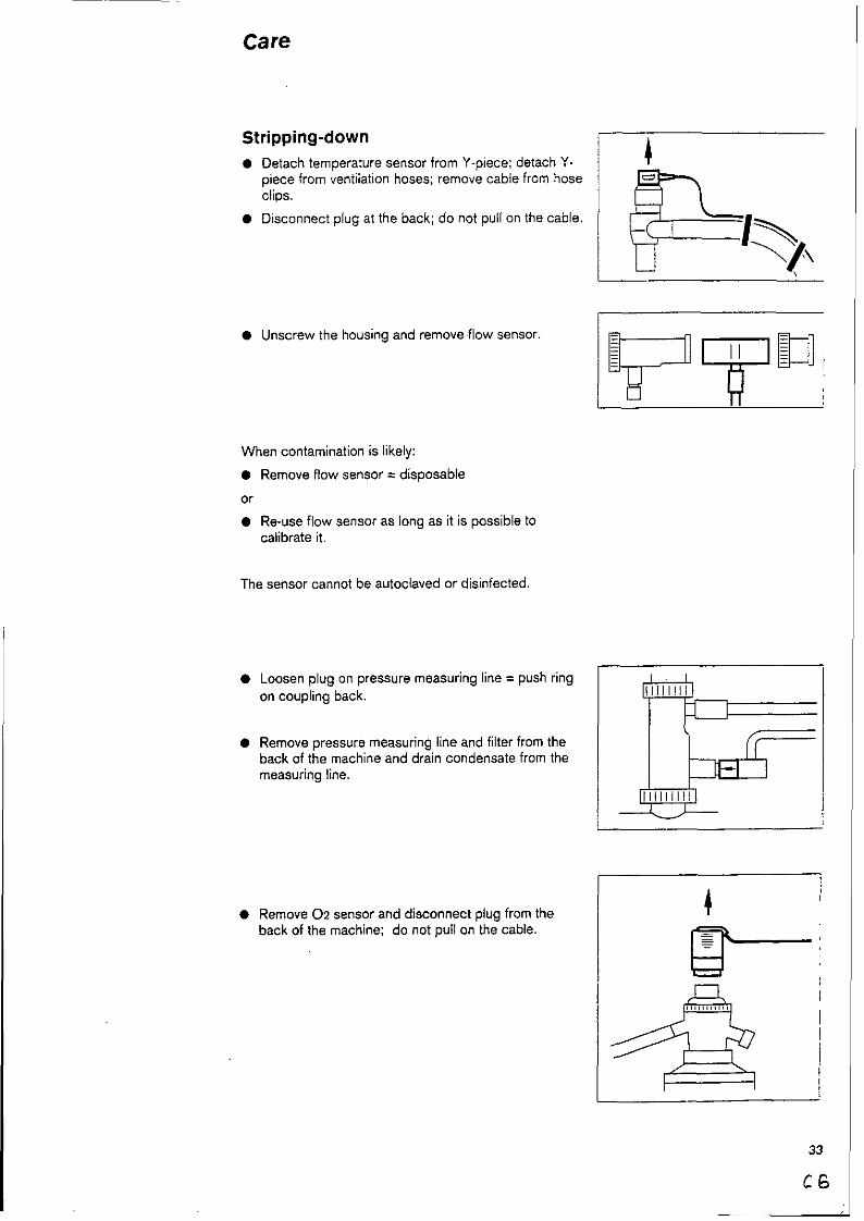
Stripping-down
. Detach temperature sensor from Y-piece; detach Y- piece from ventilation hoses; remove cable from hose clips.
. Disconnect plug at the back; do not pull on the cable.
l Unscrew the housing and remove flow sensor
When contamination is likely:
l Remove flow sensor = disposable
or
0 Reuse flow sensor as long as it is possible to calibrate it.
The sensor cannot be autoclaved or disinfected.
Loosen plug on pressure measuring line = push ring
on coupling back.
Remove pressure measuring line and filter from the back of the machine and drain condensate from the measuring line.
0 Remove 02 sensor and disconnect plug from the back of the machine; do not pull on the cable.
33
C6

Care
Detaching Oz sensor capsule
1 Unscrew cap from sensor housing.
2 Take out sensor caosule.
The plug of the anaesthetic agent sensor remains connected. II 21 /
Disinfecting/Cleaning/Sterilizing
Use surface disinfectants for disinfection. To ensure that materials are compatible, we recommend preparations based on
- aldehydes - alcohols
quaternary ammonium compounds.
Do not use
. phenols - halogen-releasing compounds . strong organic acids - oxygen-releasing compounds.
For users in the Federal Republic of Germany we recommend only disinfectants given in the current DGHM list (DGHM: German Society for Hygiene and Microbiology). For users in other countries, we also recommend the above preparations.
Do not autoclave or disinfect in liquid
Wipe any soiling off the housing or cable with a damp disposable cfoth. Wipe any soiling off the wire screen of the ?.ensor capsule with a disposable cloth lightly wetted with distilled water.
Sterilize in ethylene oxide at not more than 50°C; follow the prescribed airing times
Disinfect in Aseptor 9000 using the 45°C programme in accordance with the Aseptor Instructions for Use.

Care
Temperature sensor, pressure measuring line
with filter, measuring connection of flow.sensor
0 Wipe any soiling off with a damp disposable cloth.
l Sterilize in hot steam at 134°C.
PM 8030 and sensor cable from flow sensor
0 Wipe any soiling off with a damp disposable cloth,
0 Wipe disinfection with, for instance, Buraton 10 F (Messrs. Schiilke & Mayr, Norderstedt). Follow manufacturer’s instructions.
Alternatively
0 Disinfect in Aseptor 9000 using the 45°C programme - in accordance with Instructions for Use. First wipe off any soiling with a damp disposable cloth.
Before re-use
0 Re-assemble monitor, pages 6 to 6.
0 Check function, page 36.
l Immediately before use on patient. carry out check of monitor function, page 16.
35
C8

Checking Function
after assembly. at least every 2 weeks,
Self-test of machine
l Switch on mains power:
The monitor carries out a self-test: The internal programme memory is tested. The software and language versions are displayed. All LEDs and display elements are lit; a single tone sounds.
Display: Dr8ger PM 8030
The alarms for monitoring are tested.
The self-test is completed in about 30 seconds.
For operation with Monitorbus:
0 Set ventilator to IPPV.
1 The green LED goes out, the PM 8030 is in measuring mode.
0 Calibrate flow sensor, page 13.
0 Calibrate 02 sensor, page 11.
0 Calibrate anaesthetic agent sensor, page 15.
l Check pressure measurement, page 17.
l Check temperature measurement, see below.
Checking temperature measurement
Pmean AW-Temp Freq xx
Remove temperature sen.wr from Y-piece and expose to ambient air.
Select the display for ailway temperature:
Aftar about 1 minute, room temperature is displayed.
Re-insert temperature sensor in Y-piece.
36 c.3

Maintenance intervals
In accordance with DIN 31 051:
Inspection = determining actual condition
Service = measures to maintain specified condition
Repair = measures to re-establish specified condition
Maintenance = inspection, septic?, and, if necessary, repair
Clean and disinfect monitor and monitor components before maintenace. and also before dispatch for repair.
02 sensor replace, when calibration is no longer possible
Bacterial filter in replace after 1 year pressure measuring line
Pressure measuring replace if damaged, or after 1 year at the line (silicone latest rubber hose and socket)
NiCd battery for replace after 2 years by trained serviceman mains failure alarm
Digital component lithium battery for data protection
Inspection and service
replace after 3 years by trained serviceman
every six months by trained serviceman

Configuration
Setting language of display texts
PM 8030 is supplied by the manufacturer with German
display texts.
Optional alternatives are available in English, French,
Spanish, Italian and Dutch.
Switch PM 8030 to Standby, green LED is lit.
Display:
Standby
Keep button pressed for at least 3 seconds:
Display:
configuration
lanauaae RS 232 sens.
Select >tanguage< = turn knob and confirm = press knob
Display:
language CD>
GiSFDEINL
GB = English
F = French
D = German
E = Spanish
I = Italian
NL = Dutch
The actual language used is indicated by < > on the
right in the top line.
Select the desired language and confirm.
Press button repeatedly, until:
Display:
Standby
Or
Wait 30 seconds (time out)

Configuration
Interface protocol for PM 8010 or PM 8020
PM 8030 prints out measured vall;es and warnings according to the MEDIBUS format ‘n real time via the RS
23%interface.
1
2
3
2
4
2
4
2
4
3
2
4
3
2
0
Switch PM 8030 to Standby; gr?en LED is lit.
Display:
Standby
Keep button pressed for at leasi 3 seconds:
Display:
configuration
lanquaae RS232 sens.
Select >RS 232< = turn knob and confirm = press knob.
Display:
RS 232 <printer>
MEDIBUS printer rate
Select >rate< and confirm.
Display:
rate/100 baud <96>
0 12 24 46 Ss 192
The actual setting is indicated by < > on the right in the top line.
Select desired baudrate and confirm
for PM 8010 1200 baud <12>
for PM 8020 19200 baud <I 92>
Press button:
Display:
RS 232 <MEDINS>
MEDIEUS printer rate
Select >MEDIBUS< and confirm.
Press button repeatedly until:
Display:
Standby
Dr
Wait 30 seconds (time out)
39
c12

Configuration
Interface protocol for printer
PM 8030 is preset by the manufacturer for the connection of a printer:
Transfer rate 9600 baud
interval time for measured value 5 minutes
Output of warning messages “Warning” on
No output of caution messages “Caution” off
1
2
3
2
4
2
4
2
4
3
2
4
2
4
2
4
3
2
Switch PM 8030 to Standby; green LED is lit.
Display:
Standby
Keep button pressed for at least 3 seconds:
Display:
configuration m RS 232 sensor
Select >RS 232~ = Urn knob and confirm = press knob
Display
RS 232 <printer>
MEDIBUS printer rate
Select xate< and confirm.
Display:
rate/100 baud <96>
0 12 24 48 96 192
The actual setting is indicated by < > on the right in the top line.
Select desired baudrate and confirm.
Press button briefly.
Display
RS 232 <printer> MEDIBUS printer rate
Select sprinter< and confirm.
Display:
printer <5>
&Q warning caution
Selecr >data< and confirm.
Display:
data/min <5>
1 2 5 10 on
Select desired interval time for measured value print- out and confirm.
Press button and select “Warning”.
Display:
warning <on>
on off Warning <on> = warning messages are given Warning <off> = warning messages are not given.
40
Configuration
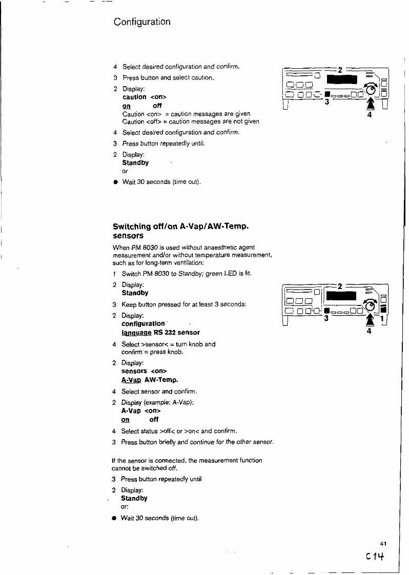
Select desired configuration and confirm
Press button and select caution.
Display: caution <on> Q!! Off
Caution <on> = caution messages are given Caution <off> = caution messages are not given
Select desired configuration and confirm
Press button repeatedly until:
Display: Standby or
Wait 30 seconds (time out).
Switching off/on A-VaplAW-Temp. sensors
When PM 8030 is used without anaesthetic agent measurement and/or without temperature measurement, such as for long-term ventilation:
1
2
3
2
4
2
4
2
4
3
Switch PM 8030 to Standby; green LED is lit.
Display: Standby
Keep button pressed for at least 3 seconds:
Display: configuration. lanauaqe RS 232 sensor
Select xensor< = turn knob and confirm = press knob.
Display: sensors <on>
&&T@ AW-Temp.
Select .sensor and confirm.
Display (example: A-Vap): A-Vap <on> on Ofi
Select status xff< or xn< and confirm.
Press button briefly and continue for the ofher sensor,
If the sensor is connected, the measurement function cannot be switched off.
3 Press button repeatedly until
2 Display: Standby or:
l Wait 30 seconds (time out).
41
Cllf

What’s What
Front
1.7 1.6 1.5 1.4 1.3
1.8
1.9 1.10 1.11 1.12 1.13 1.14 1.15
1.1
1.2
1.3
1.4
1.5
1.6
1.7
.1.8
1.9
Button for operating mode. Switches between measuring mode and standby code green LED is lit in standby mode
Button to select sensor calibration green LED flashes during selection and is lit’continzously during calibration
Light to indicate stored warning message
Red warning LED below, yellow caution LED above
Display “Alarm tone switched off for 2 minutes”
Dialogue and display window with selector button :o change display, or for selection of language and interface
Strip display for ventilation pressure Paw or tidal vciume VT with selector button
Display for the 02 measured value and display for foiver limit value for 02
Display for anaesthetic agent concentration in fresh gas with selector button for anaesthetic agent
1 .lO Display for expiratory minute volume VE or tidal voIu.zvs VT with selector
1.11
1.12
1.13
1.14
1.15
but&.
Selector button for limit values
LEDs to indicate selected anaesthetic agent
Button to switch off alarm tone for 2 minutes and :o set volume of alarm tone
Button to display stored warning messages
Selector knob to~select or adjust = turn to confirm = press
42

What’s What
2.1 2.2 2.3 2.4 2.5 2.6 2.7 2.9
2.1
2.2
2.3
2.4
2.5
2.6
2.7
2.8
2.9
2.10
2.11
fi
Mains ccnnection with mains fuse (2x) and mains switch
Potent&i equalisation pin to connect an additional earth line
Connec:ion for Drsger Monitorbus
Connec:ion for identification of anaesthetic vaporiser (optional)
RS 232.C interface to connect PM 8010 Patient Monitor or PM 8020 Data Masager or a printer
Connec:ion for additional digital interface (optional)
Connecr:on for anaesthetic agent sensor
Connec:ion for temperature sensor
Connec:ion for flow sensor
Connection for 02 sensor
Spigot for pressure measuring line
6 DIN IEC 601, para 19, table 4: max. perrzissible earth leakage current 0.5 mA
2.11

Technical Data
Ambient conditions
During operation: Temperature Atmospheric pressure Rel. humidity
During storage: Temperature Atmospheric pressure Rel. humidity
Displays For measuring and limit values as well as text displays
For Paw(t) and VT(t)
Pressure displays Airway pressure Paw
Range
PEEP Plat. Peak Pmean
Range PEEP Plat. Peak Mean Resolution Accuracy
02 display Range Resolution Accuracy Calibrated with 21% 02 by vol.
Calibrated with 100% 02 by ~01.
Tidal volume VT Range
Tidal volume VT Range Resolution Accuracy
Minute volume \iE Range Resolution Accuracy
Frequency Range Resolution Accuracy
15 to 4ooc 900 to 1100 hPa 10 to 90% (below dewpoint)
- 20 to 60°C 500 to 1100 hPa < 96% (below dewpoint)
LED displays together with a two- line vacuum fluorescence display (VF display)
40.stage LED strip display
LED strip display -10 to 60 mbar Limit values brighter
numerical display VF display, 2 digit -2 to 20 mbar -10 to 96 mbar 1 mbar t 4% of measured value, at least > 1 mbar
7.segment LED, 3 digit 5 to 105 vol. % 1 vol.%
f 3% by vol. in measuring range 6 to 16% by vol. + 1 vol.% in measuring range 16 to 30% by vol. i. 3 vol.% in measuring range 30 to 50% by vol. f 5 vol.% in measuring range 50 to 60% by vol.
i 3% by vol. in measuring range 0 to 100% by vol.
LED strip display Oto1.5L
numerical 7-segment display, 3 digit 0.02 to 9.99 L 0.01 L k 6% of measured value, at least > 0.01 L (subject to calibration conditions and 1013 hPa)
numerical 7.segment display, 3 digit 0 to 99.9 L/min 0.1 Umin f 6% of measured value (subject to calibration conditions and 1013 hPa)
numerical display. VF display, 2 digit 0 to 60lmin i. llmin C llmin

Technical Data
Inspiration gas temperature Range Resolution Accuracy
Anaesthetic agent concentration Range Resolution Accuracy
Data interface (not for the control of the anaesthetic or intensive care ventilator) RS 232-C
numerical display, VF display, 2 digit 20 to 50°C 1°C IO.5;C in measuring range 30 to 41°C
numerical 7-segment display, 2 digit 0 to 9.9% by vol. 0.1% by vol. 5 10 % of measured value, at least > 0.1% by vol.
Plug Pin plates
Galvanic separation
Operating Data:
Voltage
Current
Mains fuse
Dimensions W x H x D
Weight
Classification
25 pole Sub 0 1 screening 2 - TxD 3. RxD 7.GND
1.5 kV
100 to 240 V 5OkiO Hz
max. 0.4 A
T 2 A DIN 41662 (2x)
425 x 66 x 300 mm
3.3 kg .
I, type 6 R co n orming to DIN IEC 601/l para. 19, table 4 f max. permissible earth leakage current 0.5 mA
Temperature and flow sensor. galvanic, separated from protective conductor type BF permissible patient current 0.1 mA
Manufacturer’s certificate for radio suppression
The manufacturers certify that PM 6030 is radbsuppressed to conform to the guidelines contained in Regulations 1046 of the German Federal Post.

Order List
Basic Unit PM 8030 with accessories:
Mains cable ‘2m Meastmng connection Pressure measuring line Flow measuring cable Flow sensors (5 err) 02 sensor housing Plug adaptor for 02 sensor housing 02 senm capsule Cap for 02 sensor
Accessories required
For anaesthetic agent measurement sensor required:
Sensor universal for connection to Otiger anaesthetic machines and those of other manufacturers
62 01 414
82 go 033
0,
Sensor Sulla/Trajan
for connection to Drgger Sulla 608, Trajan 806 anaesthetic machines
82 90 032
Sensor Titus A for connection to Driger Titus A anaesthetic machine
or
Sensor NS 656, AV 1
for connection to Driger NS 656 Anaesthetic Spiromat and AV 1 Anaesthetic Ventilator (Vapor mounted on the right-hand side)
Sensor AV 1 82 90 031 for connection to Dreger AV 1 Anaesthetic Ventilator (Vapor mounted on the left-hand side)
Test adapter 66 01 349
Special accessories
for temperature measurement:
Temperature sensor
Y-piece with connection for temperature sensor
Hose clips (set of 10).
for data communication:
with PM 8020 data cable ‘PM 8020”
with PM 6010 data cable ‘PM 6010”
for printer connaction
Monitorbus cable 45 cm
82 90 328
82 90 030
84 05 371
M 30 543
64 04 047
86 00 133
85 00 337
86 00 133
M 30 893

Order List
Spare parts
Flow sensor (5 off)
Flow measuring cable
02 sensor capsule 68 50 645
02 sensor housing 68 50 720
caps for 02 sensor (5 off) M 21 482
Pressure measuring line (socket, filter, hose, plug) 83 02 841
Measuring connection M 28 833
Temperature sensor 84 05 371
Y-piece with connection to temperature senscr M 30 543
Mains cable 2 m 1807323
84 03 735
83 01 795

Appendix
Flow Measurement -
Measuring principle and signal processing
The sensor works on the principle of a constant temperarure hot-wire anemometer. The breathing gas flows through a tube which contains two platinum wires. One of the wires is heated while the other compensates for gas temperature.
The transfer of energy from the wire to the breathing gas is dependent on mass flow. As a result the measurement of volume is influenced by ambient
air pressure.
If ambient air pressure changes by 20mbar the measurement accuracy changes by 2% (relative to normal pressure 1013 hPa)
Gas compensation
PM 8030 automatically corrects the influence of breathing gases of different compositions (Oz/NzO mixture) on flow measurement. During inspiration (no gas flow to sensor) the gas composition is identified. Linearisation is carried out using different calibration tables for gas mixtures of Oz/NzO or of air and OZ.
Classification of breathing models
The calibration of the sensor applies to defined flow conditions. Artefacts, arising from fluctuations of the gas column in the hoses or pressure surges during the closing or opening of valves are eliminated by using a specific model of the breathing process. This process is based on the physiological expiration flow model where there is a steep increase in ilow at the beginning of expiration. A minimum flow and a minimum volume must be achieved to establish a valid breathing model:
\jE minute volume Umin Minimum volume mL
VE < 2 15
2<V~<4 30
4<V~<6 50
VE > 6 90
Determination of \SE
i/E measurement is independent of the breathing model. The measured value VE is integrated from the flow for a 30 second time period.
Definition of PEEP and Plateau pressure
PEEP (positive endexpiratory pressure) is the airway pressure at the end of expiration.
Plateau pressure is the airway pressure measured 16 milliseconds before the start of expiration.
This definition of PEEP and Plateau pressure is related :o the breathing model described above.

Appendix
02 Measurement Measuring principle and signal processing
The 02 sensor functions according to the galvanic cell principle. Oxygen molecules from the gas mixiure for measurement diffuse through a plastic membrane into an electro-chemical cell and are reduced at noble metal electrodes.
Simultaneously oxidation occurs at a base metal electrode which is eroded as a result of the oxidation process, and thus the life of the sensor is limited. The current flowing through the cell is proportional to the oxygen partial pressure in the gas mixture.
At a constant pressure and temperature of the gas mixture being measured, the measured value is directly proportional to the oxygen partial pressure.
Particularly characteristic of the 02 sensor are the two electrically separated cathodes which give two independent redundant measuring signals. Both measuring signals are evaluated electronically and the mean value of both individual signals is displayed.
Where the individual signals differ beyond a permissible tolerance due to external or internal malfunction, the display will switch off automatically. This prevents faulty displays and subsequent faulty interpretation.
I
Anaesthetic agent measurement Measuring principle
The anaesthetic agent measurement works with the Drsger Iris sensor (IRIS = InfraRed Inhalation Sensor). The anaesthetic agents halothane, enflurane and isoflurane absorb a pulsed light beam inside the measuring chamber. At a constant pressure, the reduction of light intensity (compared to a calibration point) can be described approximately as the sum of two exponential functions.
In the selected wavelength ranges changes in the composition of the gas mixture (NzO etc.) give no measurable cross sensitivity at the required
accuracy.
PM 8030 is calibrated by the manufacturer at a temperature of 22°C. normal pressure of 1013 hPa.
Since measurement depends on gas density, the measured value must be corrected when there is any significant deviation from normal pressure (1013 hPa) and temperature (22%):
Ckorr. = c It?. 273+T P 295
:a,,. =correct measured value
= measured value
PO = normal pressure 10 13 hPa
Y = actual atmospheric pressure hPa = actual temperature “C
No correction for pressure is required for comparing the concentration set on the Drsger anaesthetic agent vaporiser Vapor 19.n and the display value on PM 8030.
See Driger Vapor 19.n Instructions for Use.
49
48

Appendix
Explanation of terms used
Abbreviation Explanation
A-Vap
AW-Temp
Enf
Freq.
FiOz
Hal
Is0
MODE
Paw
Peak
PEEP
Plat.
Pmean
Default
VE
VT
Anaesthetic agent concentration in fresh gas
lnspiratory gas temperature in the airway
Anaesthetic agent enflurane
Ventilation or breathing frequency
lnspiratory oxygen concentration
Anaesthetic agent halothane
Anaesthetic agent isoflurane
Operating mode:
% by vol.
“C
bpm
% by vol.
monitoring during automatic ventilation <IPPV> (display for complete alarm monitoring) Or
during manual ventilation or spontaneous breathing <MAN/SP> (display for reduced alarm monitoring)
Airway pressure
Peak pressure
Positive endexpiratory pressure
Plateau pressure
Mean pressure
Pre-programmed default values
Expiratory minute volume
Tidal volume
mbar
mbar
mbar
mbar
Llmin
L

Index
Accessories.. ............................................ 8. 47 Accuracy .................................................. 49 Advisory messaces.. ................................ .31, 32 Airway pressure ........................................ 4. 18. 24 Airway tempera:xe.. ................................ .4. 24. 36 Alarm tone
switch on.. ............................................ .26 suppress.. .............................................. 26
Anaesthetic age;;: concentration .............. (50 Anaesthetic age% sensor .......................... 6. 7, 15
wamxng-up phase ................................. 15 measurement ,c;inciple.. ........................ .40
Anaesthetic agem vaporiser.. ................... .15, 21 Apnoea ..................................................... 29 Appendix ................................................. .48 A-Vap ....................................................... 4, 15, 18, 21,
23, 31, 41 AW-Temperature ..................................... .19, 24, 30, 41
Bacterial filter.. .......................................... 37 Brief description ...................................... .5 Button symbols.. ...................................... .5
Calibration ................................................ 1 1 02 sensor.. ........................................... .l 1 Flow sensor.. ........................................ .13 A-Vap sensor.. ...................................... .15
Care ......................................................... 33 Caution messages ................................... .30 Checking fun&x.. ................................... 16 Cleaning ................................................... 14, 34, 39 Cold start ................................................ .23 Communication.. ...................................... .27 Condensate.. ........................................... .7, 8 Configuration.. ......................................... .38
Language .............................................. 38 Interface protocol for PM 801018020.. . ..3 9 Interface protocol for printer.. ................ .40 A.VaplAW.Temp. sensor switch off/on...4 1
Confirm = press inob.. ............................. 11, 15, 18 Contamination.. ......................................... 33 Coupling for pressure measuring line ..... ...?
Data cable ............................................... .8, 46 Data communicarion ................................ .46 Disconnection.. ........................................ .24 DisinfectionlDisiciecting ............................ 34 Disinfectant.. ............................................. 34
Earth cable ............................................... 9 Earth connection.. ..................................... 9
Fault ........................................................ 29 Filter ......................................................... 34, 37, 47 FiO2 ......................................................... 4, 18 First operation .......................................... 10 Flow sensor.. ........................................... .8, 13. 14
Measuring principle.. .............................. 48 Flushing.. .............. . ................................... 12 Frequency ................................................ 24 Front.. ...................................................... .42
Intended use.. .......................................... .4 Interface protocol.. ................................... .39, 40 IPPV (monitoring). ..................................... 18
Language versions.. ................................. .lO, 16 Leak test ................................................... 24 Limit values ............................................... 18. 19, 20,
21,22 Linearity .................................................... 13 Lithium battery .......................................... 37
Mains failure alarm.. ................................. .10 Mains fuse ................................................ 43, 45 Mainsplug ................................................ 10, 16 Mains voltage.. ......................................... .9 Maintenance intervals.. ............................. .37 MAN/SP ................................................... 18, 32, 51 Measurement error .................................. .44, 45 MEDIBUS ................................................. 27, 39 Minute volume.. ........................................ .23, 43, 45 Minute volume (VE) .................................. .48, 50 Mode ........................................................ 18, 22, 51 Monitorbus ........................... .................. .9, 27 Monitoring ............................................... .22 Monitoring parameter.. ............................. .4, 18
NiCd battery ............................................. 10
02flush .................................................... 15, 17, 30 02 sensor ................................................. 7, 11, 27, 34
warming-up time ................................... .l 1 measurement principle ........................... 49
Order list .................................................. 46 Operation ................................................. 16
Paw .......................................................... 20, 24, 29, 44,50
Peak ......................................................... 24, 44, 50 PEEP ........................................................ 24, 44, 48, 50 Plat .......................................................... 24, 44, 50 Plateau pressure.. .................................... .20. 48 Plug adapter. ............................................ 7, 46 Potential equalisation ............................... .9, 43 Preparation.. ............................................ .6 Pressure measuring line.. .......................... 6, 34, 37 Priority ...................................................... 25, 28 Printer ....................................................... 28, 40
Rate .......................................................... 39 Rear ........................................................ .44 Records .................................................... 28 Remedy ............................. . ...................... 29 RS 232-C interface.. ................................. 4, 8
Select = turn knob .................................... 18 Selector knob .......................................... .42 Self.test of machine ................................. .16 Sensors .................................................... 6. 7 Sensor capsule (02) ................................. 46, 47 Sensor replacement.. ............. . .................. 1 1 , 13, 15
Index
Service.. ................................................... 3, 37
Settings lost.. ............................................ 31 Setting ranges .......................................... 19 Shut-down.. ............................................. .26 Spare parts.. ............................................. 47 Special accessories.. ............................... ,46 Spontaneous breathing.. .......................... .22, 32, 51 Standard limit values.. .............................. ,19 Standby.. ................................................. .lO, 16 Steriiizing .................................................. 34 storage .................................................... 44 Sound volume.. ........................................ .lO, 26
Strip display.. ........................................... ,24, 43, 45
Technical data ......................................... ,44 Temperature sensor.. ............................... .6, 34
Test adapter for 02 sensor ...................... .12 Tidal volume.. ............................................ 23, 24, 45 Time out .................................................. .36, 39, 40, 41 Tone sequence.. ....................................... 25, 26
Transfer rate ............................................ .40
Warning messages .................................. .25, 29 What’s What ........................................... ,42 Wipe disinfection ..................................... .35
Y-piece.. .................................................. .6, 17

magerwerk Aktiengesellschafl ~edm Republic of Germany ixi Podach 1339 5 Moislinger Allee 53-55
o-2400 Liibeck 1
90 27 542~ GA 6494.100 e ** Drdgerwerk. AG
2nd edxan November 199, Subpa :o alteration
Top Related