


Languages
Pages
Legal


Installation Instructions
Original Instructions
PowerFlex DC Field ControllerBulletin Number 23PFC
Topic Page
Summary of Changes 2
Product Advisories 2
Product Overview 3
Catalog Number Explanation 3
Storage and Handling 3
Required Tools/Components 4
Required System Components 4
Optional System Components 4
Field Controller Nameplate Data 5
Product Dimensions and Weights 6
Enclosure Requirements 8
Site Requirements 8
CE Conformity 9
Mount the PowerFlex DC Field Controller 12
Remove the Covers 12
Isolation Transformers / AC Input Line Reactors 13
AC Input Contactor 15
Install an SCR Overvoltage Protection Device 15
Ground the PowerFlex DC Field Controller 16
Grounding for Installations in an Ungrounded or High-impedance, Neutral Ground, or System 17
Input Power Circuit Protection 21
Control Power Circuit Protection 21
Wire the PowerFlex DC Field Controller 22
Install the Fiber-optic Option Module 32
Install a Communication Adapter 32
Install an Optional Analog and Digital I/O Expansion Circuit Board 32
Install an Optional 115V AC to 24V DC I/O Converter Circuit Board 32
I/O Wiring 33
Install the Protective Covers and Route I/O and Control Wires 39
Connect the Human Interface Module 39
Additional Resources 40

PowerFlex DC Field Controller
Summary of ChangesThis publication contains new and updated information as indicated in the following table.
Product Advisories
Topic Page
Removed the EAC mark from the sample Field Controller Nameplate Data label. 5
Removed the Isolation Transformers for 200V AC Input Field Controllers table from the Isolation Transformers section. 14
Updated the Install an SCR Overvoltage Protection Device section to include information about the voltage clamp kit (cat. no. 23P-FCOVPD-x-Fx). 15
Added Voltage Clamp Kits and Dampening Resistor (RB) Kit Selection selection tables 16
Changed the Factory Default in Terminal Block 1 from 1 “Volt Ref A” to 5 “Current Ref” in the I/O Terminal Block 1 Designations table. 34
Updated the first two rows of the Digital and Analog I/O Wiring Examples table. 36
Updated the waste statement and moved to back page. 42
Qualified Personnel
ATTENTION: Allow only qualified personnel, familiar with DC drives, field controllers, motors and associated machinery, to plan or implement the installation, startup and subsequent maintenance of the system. Failure to comply can result in personal injury and equipment damage.
Product Safety
ATTENTION: An incorrectly applied or installed field controller can result in component damage or a reduction in product life. Installation or application errors, such as, an undersized field, incorrect or inadequate DC supply, or excessive air temperatures around the product can result in malfunction of the system.
ATTENTION: This product contains ESD (Electrostatic Discharge) sensitive parts and assemblies. Static control precautions are required when you install, test, service, or repair this assembly. If ESD control procedures are not followed, component damage can result. Follow industry guidelines for static control precautions.
Class 1 Light-emitting Diode Product
ATTENTION: Hazard of permanent eye damage exists when using optical transmission equipment. This product emits intense light and invisible radiation. Do not look into module ports or fiber-optic cable connectors.
2 Rockwell Automation Publication 23PFC-IN001B-EN-P - December 2018

PowerFlex DC Field Controller
Product OverviewThe PowerFlex® DC Field Controller provides three-phase, four quadrant (reversing) DC motor or generator field control. The PowerFlex DC Field Controller can be used for standalone DC motor field control applications or with a PowerFlex DC Digital drive or PowerFlex DC Standalone Regulator (SAR). A fiber-optic interface option module or digital and analog I/O provides transmission of the reference, feedback, and status signals between the drive or regulator and the field controller.
In the standalone mode, the PowerFlex DC Field Controller provides power to a DC motor field with a fixed reference by using fixed I/O. The PowerFlex DC Field Controller can also be used to supply various DC non-motor loads (highly inductive loads) such as galvanic applications, electromagnets, synchronous motor excitation circuits, and more.
Catalog Number ExplanationUse the catalog number explanation to verify that the field controller you received matches the product your ordered.
Storage and HandlingIt is recommended that you unpack and handle the PowerFlex DC Field Controller only when you are ready for installation. If it is necessary to store the field controller before installation, follow these storage guidelines to provide satisfactory operation at startup and to retain the product warranty coverage:
• After receipt and inspection, repack the field controller in its original shipping container and store in a clean, dry place.• Store the packaged product where the ambient temperatures do not exceed -25°C (-13°F) or 55 °C (131 °F).• Store the product where the range of relative air humidity does not exceed 5…95%, noncondensing.• Store the packaged product at an altitude of less than 3,000 meters (10,000 ft.) above sea level.
ATTENTION: Remove all loose packing materials, including the containers of desiccants (if any), from the field controller enclosure before you mount and energize the field controller.
Position
a b c
aDevice
Code Type
23PFC PowerFlex DC Field Controller
bInput Voltage
Code
cDC Output Amperage
Code
23PFC B 017
23PFC
B
D
60...200V AC, ±10%, 3 Phase
230...500V AC, ±10%, 3 Phase
Voltage Range
Amps
017
060
120
245
365
570
17
60
120
245
365
570
1-5 6 7-9
Rockwell Automation Publication 23PFC-IN001B-EN-P - December 2018 3

PowerFlex DC Field Controller
Required Tools/ComponentsThis table contains the tools that are required to install the PowerFlex DC Field Controller.
Required System ComponentsThe following system components are required for PowerFlex DC Field Controller installations:
• When the PowerFlex DC Field Controller is used as a motor/generator field supply, an overvoltage protection device (voltage clamp) and dampening resistor must be installed on the field controller load. See page 15 for details.
• When the PowerFlex DC Field Controller is connected to a network, a communication adapter is required (20-COMM-x, 20-CXCOMMAC-PS1, 20-XCOMMDC-BASE, 1769-SM1, 1203-SNM, 1203-SSS, or 1203-UDB). See the PowerFlex Digital DC Drive Technical Data, publication 20P-TD001, for more information on these kits.
Optional System ComponentsWhen the PowerFlex DC Field Controller is used in applications with a PowerFlex DC drive (with firmware revision 7.001 or later) or PowerFlex Standalone Regulator (with firmware revision 7.001 or later), these optional kits can be purchased to provide fiber-optic communication:
• PowerFlex DC Fiber-optic Interface option module, cat. no. 20P-S5H781, and one of these fiber-optic cable kits:• Cat. no. SK-20P-2950, 3 m (9.8 ft.)• Cat. no. SK-20P-29501, 5 m (16.4 ft.)
Tool Description Details
Crimp tools For cable terminals
Flat-nose screwdriver 3 mm (0.12 in.), 5 mm (0.19 in.), 6.4 mm (0.25 in.)
Hexagonal socket wrench 5 mm, 8 mm 10 mm
Phillips screwdriver/bit #1, #2
Torx screw driver/bit T20, T25
Wire cutter –
4 Rockwell Automation Publication 23PFC-IN001B-EN-P - December 2018

PowerFlex DC Field Controller
Field Controller Nameplate DataThe PowerFlex DC Field Controller contains a data nameplate label on the side of each module. This nameplate identifies the specific model number, frame size, serial number, and applicable AC input power and DC output power data. Include this information when communicating with Rockwell Automation® personnel about this product.
Frame SizesSimilar PowerFlex DC Field Controller ratings are grouped into two frame sizes (A and B) to make ordering spare parts and field controller dimensions simpler. The module frame size appears just below the certifications section on the right side of the data nameplate label. See the PowerFlex Digital DC Drive Technical Data, publication 20P-TD001, for a list of field controller catalog numbers and their respective frame sizes.
Firmware RevisionThe original firmware revision of the field controller, as shipped from the factory, appears just below the series letter on the right side of the data nameplate label. If the firmware revision has been upgraded since the field controller was shipped, you can view the current version on the HIM (if installed). See the PowerFlex DC Field Controller Programming Manual, publication 23PFC-PM001, for details about the HIM.
EXAMPLE ONLYCat No. 23PFCD017
UL Type OPEN/IP20
Input: 500 VAC max 50/60 Hz 14.0 A 3 Phase
Output: 520 VDC max 17.0 A Regen
Regulator Power: 115 / 230 VAC 50/60 Hz 1.0 / 0.5 A 1 Phase
MFD, in 2017 on week 20 制造于2017年,第20周
Product of Italy
Rockwell Automation, 1201 S. 2nd St., Milwaukee, WI 53204, USA
Serial Number: J01A0001
*K20E0013*
IND. CONT.LISTED
C R US
31KF
Series: AI/O: 24VDC (Standard)
N223
25KCC-REM-RAA-20P
Original Firmware V1.001
Frame: A
Original Firmware Revision
Frame Size
Rockwell Automation Publication 23PFC-IN001B-EN-P - December 2018 5

PowerFlex DC Field Controller
Product Dimensions and WeightsThis section contains the approximate dimensions and weights for frame A and frame B field controllers.
Frame A Field Controller Dimensions
Frame Size Cat. No.Weightkg (lb)
Weight with Packagingkg (lb)
Dimensions
A
23PFCB017 and23PFCD017 10.8 (23.8) 12.8 (28.2)
See Frame A Field Controller Dimensions on page 623PFCB060 and 23PFCD060 11.3 (24.9) 13.3 (29.3)
23PFCB120 and 23PFCD120 11.8 (26.0) 13.8 (30.4)
B
23PFCB245 and 23PFCD245 25.3 (55.8) 27.3 (60.2)
See Frame B Field Controller Dimensions on page 723PFCB365 and 23PFCD365 29.3 (64.6) 31.3 (69.0)
23PFCB570 and 23PFCD570 31.8 (70.1) 33.8 (74.5)
A B C A1 A2 B1
mm (in.) mm (in.) mm (in.) mm (in.) mm (in.) mm (in.)
267 (10.5) 359 (14.0) 287 (11.3) 7 (0.3) 250 (9.8) 275 (10.8)
A
B
A2
B1
C
STS
PORT
MOD
NET A
NET B
A1
6 Rockwell Automation Publication 23PFC-IN001B-EN-P - December 2018

PowerFlex DC Field Controller
Frame B Field Controller Dimensions
A A1 A2 A3 B B1 C1 C2(1)
(1) Frame B catalog numbers 23PFCB570 and 23PFCD570 only.
mm (in.) mm (in.) mm (in.) mm (in.) mm (in.) mm (in.) mm (in.) mm (in.)
311 (12.2) 275 (10.8) 16.5 (0.65) 7 (0.3) 388 (15.3) 375 (14.8) 350 (13.8) 380 (15.0)
A
A1
B1
C1
B
A2
STS
PORT
MOD
NET A
NET B
A3
45.2 (1.8)
98.5 (3.9)
53.1 (2.1)
48.5 (1.9)
147.0 (5.8) 53.1 (2.1)
48.5 (1.9)200.1 (7.9)
248.6 (9.8)
C2
Dimensions are shown in millimeters and (inches)
Rockwell Automation Publication 23PFC-IN001B-EN-P - December 2018 7

PowerFlex DC Field Controller
Enclosure RequirementsThe PowerFlex DC Field Controller is available in an IP20, Open Type enclosure only. IP20, Open Type enclosures are intended for indoor use only, primarily to provide a degree of protection against contact with enclosed equipment. These enclosures offer no protection against airborne contaminants.
Site Requirements• The controller must be mounted in a clean, dry, pollution degree 2 environment• Contaminants such as oils, corrosive vapors, and abrasive debris must be kept out of the enclosure
Maximum Surrounding Air Temperature• 0…50 °C (32…122 °F), typical• De-rate 1.25% for every 1 °C (1 °F) over 50 °C (122 °F), to 55 °C (131 °F)• Additional air cooling is required for temperatures above 55 °C (131 °F)
Minimum Mounting ClearancesMinimum clearance requirements are intended to be from module to module. Other objects can occupy this space; however, reduced airflow can cause protection circuits to fault the field controller. The field controller must be mounted in a vertical orientation as shown here and must not be mounted at an angle greater than 30° from vertical. Intake air temperature must not exceed the product specification.
Field Controller Enclosure Minimum Mounting Clearances
ATTENTION: The following information is merely a guide for proper installation. Rockwell Automation cannot assume responsibility for the compliance or the noncompliance to any code, national, local or otherwise for the proper installation of this field controller or associated equipment. If codes are ignored during installation, a hazard of personal injury and equipment damage exists.
10 mm10 mm 50 mm(0.4 in.) (0.4 in.) (2.0 in.)
10 mm(0.4 in.)
150 mm (6.0 in.)
150 mm (6.0 in.)
150 mm (6.0 in.)
STS
PORT
MOD
NET A
NET B
150 mm (6.0 in.)
STS
PORT
MOD
NET A
NET B
8 Rockwell Automation Publication 23PFC-IN001B-EN-P - December 2018

PowerFlex DC Field Controller
CE ConformityCompliance with the Low Voltage Directive and Electromagnetic Compatibility Directive has been demonstrated by using harmonized European Norm (EN) standards. The Official Journal of the European Communities publishes references to European Norm standards. PowerFlex DC Field Controllers comply with the EN standards listed here when installed according to this installation instruction.
EU Declarations of Conformity are available online at: http://www.rockwellautomation.com/global/certification/overview.page
Low Voltage Directive (LVD)• EN 61800-5-1 Electronic equipment for use in power installations.
EMC Directive• EN 61800-3 Adjustable speed electrical power drive systems Part 3: EMC product standard including specific test methods.
General Considerations• For CE compliance, the field controller installation must satisfy requirements that are related to both EN 61800-5-1 and EN 61800-3
provided in this document.• PowerFlex DC field controllers comply with the EMC requirements of EN 61800-3 when installed according to good EMC practices and
the instructions that are provided in this document. However, many factors can influence the EMC compliance of an entire machine or installation, and compliance of the field controller itself does not confirm compliance of all applications.
• PowerFlex DC field controllers are not intended to be used on public low-voltage networks that supply domestic premises. Without additional mitigation, radio frequency interference is expected if used on such a network. The installer is responsible to take measures such as supplementary line filters and enclosures to help prevent interference and follow all installation requirements of this document.
• PowerFlex DC field controllers generate notching and harmonic current emissions on the AC supply system. When operated on a public low-voltage network, it is the responsibility of the installer or user to be sure that applicable requirements of the distribution network operator have been met.
Installation Requirements Related to the Low Voltage Directive• PowerFlex DC field controllers are CE-compliant only if they are NOT connected to “corner-earthed” supply systems where one of the
three phases of the supply system has been earthed.• PowerFlex DC field controllers are compliant with the CE LV Directive when used at altitudes no greater than 2,000 m (6,562 ft).• PowerFlex DC field controllers that are provided in enclosure type IP20 must be installed in a pollution degree 1 or 2 environment to be
compliant with the CE LV Directive. Characteristics of the different pollution degree ratings are provided in the Pollution Degree Ratings according to EN 61800-5-1 table on page 10.
• PowerFlex DC field controllers can produce leakage current in the protective earthing conductor that exceeds 3.5 mA AC or 10 mA DC. The minimum size of the protective earthing (ground) conductor that is used in the application must comply with local safety regulations for high-protective earthing conductor current equipment.
ATTENTION: PowerFlex DC field controllers can produce DC current in the protective earthing conductor. This DC current can reduce the ability of residual current-operated protective devices (RCD) or residual current-operated monitoring devices (RCM), of type A or AC, to provide protection for other equipment in the installation.
Rockwell Automation Publication 23PFC-IN001B-EN-P - December 2018 9

PowerFlex DC Field Controller
Installation Requirements Related to EN 61800-3 and the EMC Directive• The field controller must be earthed (grounded) as described in this Installation Instructions.• PowerFlex DC field controllers require the use of an external EMC filter to comply with the EMC Directive and emission limits of EN
61800-3: 2004. PowerFlex DC field controllers have been tested and verified for compliance to the emission limits of EN 61800-3: 2004 by using only the specific input filters and motor cable lengths that are identified in the Standards and Limits for EMC Input Filters table.
• Output power wiring to the load must employ one of the following solutions.• Cable with a braided shield providing 75% or greater coverage• Cables that are housed in metal conduit• Cables with equivalent shielding
Continuous shielding must be provided from the field controller enclosure to the load enclosure. Both ends of the load cable shield (or conduit) must terminate with a low-impedance connection to earth.
• The load-end cable shield or conduit must terminate in a shielded connector and be properly installed in an earthed wiring box that is attached to the load. The load wiring-box cover must be installed and earthed.
• All control (I/O) and signal wiring to the field controller must use one of the following solutions.• Cable with a braided shield providing 75% or greater coverage• Cables that are housed in metal conduit• Cables with equivalent shielding
When shielded cable is used, terminate only the field controller end of the cable shield to earth with a low-impedance connection.
• Load cables must be separated from control and signal wiring wherever possible.• The maximum length of the load cable must not exceed the length that is specified in the Standards and Limits for EMC Input Filters table.
The maximum length that is specified is required for compliance with radio frequency emission limits for the specific standard and installation environment.
Standards and Limits for EMC Input Filters
Field Controller FrameCatalog Number
Standard / Limits (Compliance with Any of the Limits in the Pollution Degree Ratings according to EN 61800-5-1 Table on Page 10 Satisfies RF Emission Requirements for the EMC Directive)
EN61800-3 Category C1EN61000-6-3 CISPR 11 Group 1 Class B
EN61800-3 Category C2EN61000-6-4 CISPR11 Group 1 Class A…P < 20 kVA
CISPR11 Group 1Class A…P > 20 kVA
EN61800-3 CategoryC3…I < 100 A
EN61800-3 CategoryC3…I > 100 A
Frame A23PFCx017…23PFCx120
Compliance may be possible with supplementary mitigation (Consult factory)
Compliance may be possible with supplementary mitigation (Consult factory)
RF line filter required(2)
50 m motor cable limit
(2) Rasmi Electronics Ltd manufactures the RF 3xxx-SIEI EMC filter. xxx designates filter current rating. See the manufacturer published literature for details.
RF line filter required(2)
50 m motor cable limit RF line filter required(2)
50 m motor cable limit
Frame B23PFCx245…23PFCx570
Compliance may be possible with supplementary mitigation (Consult factory)
RF line filter required(1)
50 m (164 ft) motor cable limit
(1) Rasmi Electronics Ltd manufactures the RF 3xxx-MHU EMC filter. xxx designates filter current rating. See the manufacturer published literature for details.
RF line filter required(1)
50 m (164 ft) motor cable limit
RF line filter required(1)
50 m (164 ft) motor cable limit
RF line filter required(1)
50 m (164 ft) motor cable limit
More Stringent Limits Less Stringent Limits
IMPORTANT Use of EMC filters not listed in the Standards and Limits for EMC Input Filters table must be verified in the application. Additional filters are listed in the Alternate EMC Filters tables on page 11.
Pollution Degree Ratings according to EN 61800-5-1
Pollution Degree
Description
1 No pollution or only dry, non-conductive pollution occurs. The pollution has no influence.
2 Normally, only non-conductive pollution occurs. Occasionally, however, a temporary conductivity due to condensation can be expected, when the field controller is out of operation.
3 Conductive pollution or dry non-conductive pollution occurs, which becomes conductive due to condensation, which can be expected.
4 The pollution generates persistent conductivity that is caused, for example, by conductive dust, rain, or snow.
10 Rockwell Automation Publication 23PFC-IN001B-EN-P - December 2018

PowerFlex DC Field Controller
Alternate EMC FiltersThe following recommended filters can be used in place of the Rasmi filters that are listed in the table in the Installation Requirements Related to EN 61800-3 and the EMC Directive section on page 10.
IMPORTANT Only the Rasmi RF 3xxx-MHU, Rasmi RF-3xxx-SIEI, and EPCOS B84143B Type S081 filters have been certified for use with the PowerFlex DC Field Controller. All other filters must be verified in the application.
Rasmi and Rasmi Alternative Filters
FrameField Controller Cat. No.
Voltage Class
Rasmi Filters Rasmi Alternative Type Filters
Part Number Part Number Part Number
A
23PFCB017
200V
EMI-FFP-480-24, Code 8271 (was RF 3024-SIEI) RF 3030-FTF, Code 8082 (Rasmi / EuroTek) RF 3025-MHU
23PFCB060 RF 3100-FLP, Code 8075 (Rasmi / EuroTek) RF 3075-FTF, Code 7674 (Rasmi / EuroTek) RF 3100-MHU
23PFCB120 RF 3150-FLP, Code 8076 (Rasmi / EuroTek) RF 3180-FTF, Code 7677 (Rasmi / EuroTek) RF 3180-MHU
B
23PFCB245 RF 3320-MHU – –
23PFCB365 RF 3600-MHU – –
23PFCB570 RF 3800-MHU – –
A
23PFCD017
500V
EMI-FFP-480-24, Code 8271 (was RF 3024-SIEI) RF 3030-FTF, Code 8082 (Rasmi / EuroTek) RF 3025-MHU
23PFCD060 RF 3100-FLP, Code 8075 (Rasmi / EuroTek) RF 3075-FTF, Code 7674 (Rasmi / EuroTek) RF 3100-MHU
23PFCD120 RF 3150-FLP, Code 8076 (Rasmi / EuroTek) RF 3130-FTF, Code 7676 (Rasmi / EuroTek) RF 3130-MHU
B
23PFCD245 RF 3250-MHU – –
23PFCD365 RF 3600-MHU – –
23PFCD570 RF 3800-MHU – –
Schaffner and Schaffner Alternative Filters
Fram
e Drive Current Rating Code
Voltage Class
Schaffner Filters Schaffner Alternative Type Filters
Part Number Part Number Part Number
A
23PFCB017
200V
FN 258-30-33 FN 3258-30-33 FN 3270H-20-44
23PFCB060 FN 258-75-34 FN 3258-75-34 FN 3270H-80-35
23PFCB120 FN 258-180-40 FN 3258-180-40 FN 3270H-150-99
B
23PFCB245 FN 258-250-40 FN 3359-320-99 FN 3270H-320-99
23PFCB365 – FN 3359-400-99 FN 3270H-600-99
23PFCB570 – FN 3359-800-99 FN 3270H-800-99
A
23PFCD017
500V
FN 258HV-30-33 – FN 3270H-20-44
23PFCD060 FN 258HV-75-34 – FN 3270H-80-35
23PFCD120 FN 258HV-130-35 – FN 3270H-150-99
B
23PFCD245 FN 3359HV-320-99 – FN 3270H-250-99
23PFCD365 FN 3359HV-400-99 – FN 3270H-400-99
23PFCD570 FN 3359HV-800-99 – FN 3270H-800-99
Rockwell Automation Publication 23PFC-IN001B-EN-P - December 2018 11

PowerFlex DC Field Controller
Mount the PowerFlex DC Field ControllerThe dimensions and weights that are specified in Product Dimensions and Weights on page 6 must be considered when mounting the device. The surface that the controller is mounted on must be constructed of heat resistant materials. The heat sink can reach a temperature of 90 °C (194 °F). When lifting and handling PowerFlex DC field controllers, follow all applicable local, national, and international codes, standards, regulations, or industry guidelines for safe practices.
1. Verify the hole pattern on the panel on which you intend to mount the field controller. See Product Dimensions and Weights on page 6.
2. Install the mounting hardware. The bolts must be fully threaded into the panel before hanging the field controller.• For frame A field controllers, insert, but do not tighten, a bolt in each of the mounting holes in the panel.• For frame B field controllers, insert, but do not tighten, a bolt in each of the top mounting holes in the panel.
3. Lift the field controller into place onto the bolts that are installed in the panel.
4. Install and tighten the remaining bolts into the panel.
Remove the CoversSome protective covers must be removed to provide access to the power and I/O terminals on the field controller. Remove the upper cover only to install an optional communication adapter or service the field controller.
Remove Frame A Field Controller Lower and Terminal CoversYou must remove both the lower protective cover and the power terminal cover on frame A field controllers to access the power terminals.
IMPORTANT Verify that all mounting screws are properly tightened before and after field controller operation.
1.5 N•m (13.3 lb•in)
1.0 N•m (8.9 lb•in)
12 Rockwell Automation Publication 23PFC-IN001B-EN-P - December 2018

PowerFlex DC Field Controller
Remove Frame B Field Controller Lower Cover
1. Loosen, but do not remove, the two screws that secure the lower cover.
2. Slide the cover down until the screw heads align with the key holes and lift the cover off the chassis.
Isolation Transformers / AC Input Line ReactorsWhen connecting the field controller directly to the main distribution system, an isolation transformer or 3…5% impedance AC line reactor must be used to guard against system disturbance. If the isolation transformer provides the required 3…5% impedance, a line reactor is not required.
The type of AC line reactor that is used depends upon the following:
• Current absorbed by the AC input• AC input voltage• Relative short circuit voltage• AC input frequency
See Isolation Transformers on page 14 for a list of recommended isolation transformers. See AC Input Line Reactors and AC Contactors on page 14 for a list of recommended AC input line reactors.
STS
PORT
MOD
NET A
NET B
1.5 N•m (13.3 lb•in)
Rockwell Automation Publication 23PFC-IN001B-EN-P - December 2018 13

PowerFlex DC Field Controller
Isolation TransformersThis section contains the recommended isolation transformers for use with the PowerFlex DC Field Controller.
A customer-supplied 200V AC Three Phase Secondary Isolation Transformer must be installed with a 200V AC PowerFlex DC field controller.
AC Input Line Reactors and AC ContactorsThese tables contain the recommended AC input line reactors and AC contactors for use with the PowerFlex DC Field Controller.
Isolation Transformers for 500V AC Input Field Controllers
Frame Field Controller Cat. No.Three Phase Primary Voltage 460V AC Three Phase Secondary
kVA Voltage Isolation Transformer Cat. No.
A
23PFCD017 14
230 1321-3TW014-AB
460 1321-3TW014-BB
575 1321-3TW014-CB
23PFCD060 51
230 1321-3TW051-AB
460 1321-3TW051-BB
575 1321-3TW051-CB
23PFCD120 93
230 1321-3TH093-AB
460 1321-3TH093-BB
575 1321-3TH093-CB
B
23PFCD245 175
230 1321-3TH175-AB
460 1321-3TH175-BB
575 1321-3TH175-CB
23PFCD365 275
230 1321-3TH275-AB
460 1321-3TH275-BB
575 1321-3TH275-CB
23PFCD570 440
230 1321-3TH440-AB
460 1321-3TH440-BB
575 1321-3TH440-CB
AC Input Line Reactors and AC Contactors for 200V AC Input Field Controllers
FrameField Controller Cat. No.
DC Amps AC Line AmpsIP00 (Open Style) Line Reactor Cat No.
Line Reactor kW AC Input Contactor Cat. No.
A
23PFCB017 17 14.45 1321-3R18-A 0.75…3.7 100-C23D10
23PFCB060 60 51 1321-3R80-A 15 100-C60D10
23PFCB120 120 102 1321-3R160-A 30…37 100-D140D11
B
23PFCB245 245 208 1321-3RB250-A 45…56 100-D250ED11
23PFCB365 365 310 1321-3RB400-A 93 100-D420ED11
23PFCB570 570 485 1321-3R600-A 149 100-D630ED11
14 Rockwell Automation Publication 23PFC-IN001B-EN-P - December 2018

PowerFlex DC Field Controller
AC Input ContactorWhen an AC input contactor is used, the IEC AC1 rating of the contactor must be equal to the rated thermal (RMS) current value at the main input of the field controller. See the AC Input Line Reactors and AC Contactors tables on page 14 for a list of recommended AC input contactors. Configuration for AC contactors is as follows (see Typical Power Wiring Diagram on page 24 for an example):
When an AC contactor is used:
• Set parameter 1391 [ContactorControl] to 1 “AC Cntcr” (1)
• Set one [Relay Out x Sel] parameter and one [Digital Inx Sel] parameter to “Contactor” (default value for parameters 1392 [Relay Out 1 Sel] and 140 [Digital In8 Sel])
When a contactor is NOT used:
• Set parameter 1391 [ContactorControl] to “None” (default value) (1)
• Do NOT set either [Relay Out x Sel] parameter to “Contactor”• Do NOT set any [Digital Inx Sel] parameter to “Contactor”
(1) Par 1391 [ContactorControl] is contained in the “Advanced” parameter configuration group. See How Parameters are Organized in the PowerFlex DC Field Controller Programming Manual, publication 23PFC-PM001, for more information.
Install an SCR Overvoltage Protection DeviceWhen the PowerFlex DC Field Controller is used to supply a very inductive load like a motor/generator field or an electromagnet, an overvoltage protection device (voltage clamp) and dampening resistor must be installed on the field controller load. The PowerFlex DC Field Controller Voltage Clamp (cat. no. 23P-FCOVPD-x-Fx) can be purchased separately from the field controller to provide overvoltage protection. See the PowerFlex DC Field Controller Voltage Clamp Installation Instructions, publication 23PFC-IN002, for details. See the Voltage Clamp Kits and Dampening Resistor (RB) Kit Selection selection tables for the correct parts for your PowerFlex DC Field Controller.
The purpose of the voltage clamp is to provide a means to let the DC output current to the load decay if the power is interrupted to the field controller. If the AC power to the connected field controller is interrupted, the current in the DC output to the field starts to the decay rapidly. This rapid decay generates voltages that are in direct proportion to the rate of decay of the “field collapse.” These voltages can damage the field controller and/or the motor wire insulation. The voltage clamp is connected directly across the DC output power connections to the load and during normal operation it appears as an open circuit. See the Typical Power Wiring Diagram on page 24 for an illustration of the voltage clamp installation location.
AC Input Line Reactors and AC Contactors for 500V AC Input Field Controllers
FrameField Controller Cat. No.
DC Amps AC Line AmpsIP00 (Open Style)Line Reactor Cat No.
Line Reactor kW AC Input Contactor Cat. No.
A
23PFCD017 17 14.45 1321-3R18-B 1.5…7.5 100-C23D10
23PFCD060 60 51 1321-3R80-B 30 100-C60D10
23PFCD120 120 102 1321-3R160-B 56…75 100-D110D11
B
23PFCD245 245 208 1321-3RB250-B 93…112 100-D210ED11
23PFCD365 365 310 1321-3RB400-B 186.4 100-D420ED11
23PFCD570 570 485 1321-3R600-B 298.3 100-D630ED11
IMPORTANT An AC input contactor can only be installed when the field controller is used in standalone mode. When the field controller is connected to and controlled by a PowerFlex DC drive or SAR, an AC input contactor cannot be used with the field controller.
ATTENTION: Do not remove AC power until the field controller output (load) current is zero. Equipment damage can occur.
Rockwell Automation Publication 23PFC-IN001B-EN-P - December 2018 15

PowerFlex DC Field Controller
Ground the PowerFlex DC Field ControllerThe field controller Safety Ground (PE) must be connected to system ground. Ground impedance must conform to the requirements of national and local industrial safety regulations and electrical codes. Periodically check the integrity of all ground connections.
For installations within an enclosure, use a safety ground point or ground bus bar connected directly to structural steel. Ground all circuits, including the AC input ground conductor, independently and directly to this point/bar.
For installations in distribution systems that have ungrounded or high impedance, neutral connections or systems, see Grounding for Installations in an Ungrounded or High-impedance, Neutral Ground, or System on page 17.
Voltage Clamp Kits
Field Controller Specifications
AC Input Voltage Output Amp Rating Frame SizeVoltage Clamp Cat. No.
200 17…120 A 23P-FCOVPD-B-FA
200 245…570 B 23P-FCOVPD-B-FB
500 17…120 A 23P-FCOVPD-D-FA
500 245…570 B 23P-FCOVPD-D-FB
Dampening Resistor (RB) Kit Selection
Field Controller
AC Input Voltage Range (Vrms)
RB Resistor Value Ohms
RB Resistor SizeWatts
RB Resistor Kit Cat. No.(1)
(1) Resistor kits are IP00 / Open Type and must be installed in an enclosure.
60…100V 220 930 23P-FC-RB100
101…200V 390 930 23P-FC-RB200
201…300V 680 930 23P-FC-RB300
301…400V 1000 930 23P-FC-RB400
401…500V 1200 930 23P-FC-RB500
ATTENTION: To comply with the essential requirements of the CE Low Voltage Directive 2006/95/EC, the PowerFlex DC Field Controller cannot be powered from a corner-earthed (TN with one phase earthed) supply system. When operating a PowerFlex DC Field Controller from an IT or impedance-earthed supply system, only temporary operation is permitted after an earth fault is detected in the power system.
16 Rockwell Automation Publication 23PFC-IN001B-EN-P - December 2018
PowerFlex DC Field Controller
Typical Ground Scheme
Safety Ground (PE)The field controller Safety Ground-PE must be connected to adjacent structural steel (girder, joist), a floor ground rod, or bus bar (see Typical Ground Scheme). Ground points must comply with national and local industrial safety regulations and electrical codes.
Power FeederEach power feeder from the substation transformer to the field controller must be provided with properly sized ground cables. Bond the conduit or cable armor to the substation ground at both ends. Each transformer enclosure or frame must be bonded to ground at a minimum of two locations.
Grounding for Installations in an Ungrounded or High-impedance, Neutral Ground, or SystemThe PowerFlex DC Field Controller was designed to work in distribution systems where the isolation transformer wye neutral is connected to earth ground. PowerFlex DC Field Controllers are not designed to work in distribution systems that have ungrounded or high-impedance, neutral connections, or systems that have a phase that is referenced to earth. Symmetrical incoming power is required for correct operation.
The use of a grounded wye neutral is highly recommended to help prevent common-mode rejection problems with the feedback measurement circuits in the field controller. Possible field controller damage can occur because of inaccurate feedback measurements of the incoming AC voltage, armature voltage, or field current.
If the PowerFlex DC field controller is installed in a system with an ungrounded wye neutral or with an impedance ground connection, see Ungrounded Wye Neutral or Impedance Grounded Connections Modifications on page 18. The table contains the modifications that are required for proper installation.
IMPORTANT For PowerFlex DC Field Controllers, cat. no. 23PFCD017, 23PFCD060, and 23PFCD120 only, conductors that are used for grounding at all protective earth (PE)
terminals must be at least 10 mm2.
L1
L2
L3
U V WC D
PE1/
STS
PORT
MOD
NET A
NET B
Earth
All wires (including motor ground) must be connected inside the motor terminal box.
TransformerSafety Ground
AC M
ains S
uppl
y
AC Line Reactor
Frame A Shown
Rockwell Automation Publication 23PFC-IN001B-EN-P - December 2018 17

PowerFlex DC Field Controller
Power DistributionRockwell Automation strongly recommends the use of grounded neutral systems for the following reasons:
• Controlled path for common mode noise current• Consistent line to ground voltage reference, which minimizes insulation stress• Accommodation for system-surge protection schemes
Delta/Wye with Grounded Wye Neutral
Grounding the transformer secondary is essential to the safety of personnel and safe operation of the field controller. A floating secondary can allow dangerously high voltages occur between the chassis of the field controller and the internal power-structure components.
Ungrounded Secondary
Grounding the wye secondary neutral through a resistor is an acceptable method of grounding. In this case, in a short-circuited secondary condition, none of the output phases to ground exceed the normal line to line voltage. If a resistor is used, a ground fault detection circuit must be used to signal a ground fault to the central system.
High-impedance Ground
Ungrounded Wye Neutral or Impedance Grounded Connections Modifications
Frame Modification See
A Remove the jumper S9 on the pulse transformer circuit board (FIR1-xx-FC) Frame A Pulse Transformer Circuit Board S9 Jumper Location
B Remove the jumper S9 on the pulse transformer circuit board (FIR1-xx-FC) Frame B Pulse Transformer Circuit Board S9 Jumper Location
Ground Fault DetectorSignal to Central System to Provide Warning or Shutdown
18 Rockwell Automation Publication 23PFC-IN001B-EN-P - December 2018

PowerFlex DC Field Controller
Frame A Pulse Transformer Circuit Board S9 Jumper Location
Frame B Pulse Transformer Circuit Board S9 Jumper Location
S9
TR01 TR04 TR02 TR05 TR03 TR06
TR1 TR4 TR2 TR5 TR3 TR6
S4
S3
XR
XSW1
X4
S9
1 2 3 4 5 6 7 8 1 2 3 4 5 6 7 8
78 79 35 36 75 76 U2 V2
XSW XI2CARemove the front covers from the field controller to access the pulse transformer circuit board. See page 12 for instructions.
PE
XR
XTA
T01
T4
T1
T2 T02
T5
T3
T6
T03
T06
T04
T05
TR3
78 79 35 36 75 76 U2 V2
S9
X4
XSW
XI2CA
PE
S9
Remove the front covers from the field controller to access the pulse transformer circuit board. See page 13 for instructions.
Rockwell Automation Publication 23PFC-IN001B-EN-P - December 2018 19

PowerFlex DC Field Controller
AC Input VoltagesPowerFlex DC Field Controllers are rated for the following AC input voltages at 50/60 Hz ±5%:
Mains Circuit (Terminals U, V, W)
• Cat. No. 23PFCBxxx: 60…200V AC, ±10%, 3Ph• Cat. No. 23PFCDxxx: 230…500V AC, ±10%, 3Ph
Control Circuit (Terminals U2, V2)
• 115V ±15% or 230V ±15%, 1Ph
DC Output VoltagesThe output voltages that are shown here include an AC input undervoltage within the stated tolerance limits and a voltage drop of 4% due to an AC input line reactor. It is the same as the rated armature voltage suggested for the connected load.
IMPORTANT For frame B field controllers only, a jumper must be placed between terminals SA-SB on the switching power supply circuit board for the control circuits to work with 115V AC input. See SA-SB Terminal Block Location on page 29 for terminal block location on frame B field controllers.
AC Input Voltage DC Output Voltage
(Terminals U, V, W) (Terminals C and D)
200V, ±10%, 3Ph 210V
230V, ±10%, 3Ph 240V
400V, ±10%, 3Ph 420V (1)
(1) Voltage that is measured according to DIN 40 030 (09/93)
440V,±10%, 3Ph 460V
460V, ±10%, 3Ph 480V
480V ±10%, 3Ph 500V
500V, ±10%, 3Ph 520V (1)
20 Rockwell Automation Publication 23PFC-IN001B-EN-P - December 2018
PowerFlex DC Field Controller
Input Power Circuit ProtectionFast-acting AC input fuses are required on all field controllers to help protect the field converter. All AC input fuses must be sourced separately and are mounted externally from the field converter. The required fuses are listed in the AC Input Fuses table.
Control Power Circuit ProtectionThe 115V / 230V AC control circuit power input terminals U2 and V2 are required to be short circuit protected. This protection can be provided by using standard time-delay fuses or a circuit breaker (device). Either protective device must survive the short circuit available current of the feeder source for this circuit and the inrush current of the field controller power supply.
Size the device to help protect the wiring between the fuses or circuit breaker connections to terminals U2 and V2, and not spurious trip or blow from the inrush current. This table lists the input current characteristics of the control power supply.
Provide a power source for the control power input that is stabilized and buffered from the power system transients. The control power for multiple field controllers can be fed from one source, as long as proper distribution protection is provided.
AC Input Fuses
Cat. No. Frame Size DC Amps AC Line Amps
Bussman Mersen
FerruleFWP Type
North American FWP Type
Ferrule A70QS TypeNorth AmericanA70P / A70QS Type
23PFCx017 A 17 14 FWP-25A14F FWP-25B A70QS25-14F A70P25-4
23PFCx060 A 60 49 FWP-80A22F FWP-80B A70QS80-22F A70QS80-4
23PFCx120 A 120 98 - FWP-150A - A70QS150-4K
23PFCx245 B 245 201 - FWP-300A - A70QS300-4
23PFCx365 B 365 299 - FWP-400A - A70QS400-4
23PFCx570 B 570 467 - FWP-600A - A70QS600-4
Control Power Circuit Protection
Frame
Control Power Supply
Circuit Board ID PowerRated Input Current Inrush Input Current
115V AC 230V AC 115V AC 230V AC
A SW1-31 60 W 1 A 0.5 A 20 A 10 A
B SW2-32 110 W 1.2 A 0.7 A 15 A 7.5 A
Rockwell Automation Publication 23PFC-IN001B-EN-P - December 2018 21

PowerFlex DC Field Controller
Wire the PowerFlex DC Field ControllerFollow the guidance in this section for all power, control, and signal cable/wire connections to the PowerFlex DC Field Controller.
Cable and Wiring RecommendationsUse the following cable and space recommendations for all field controllers sizes:
Example:Space relationship between 480V AC incoming power leads and 24V DC logic leads:
• 480V AC leads are Class 2; 24V DC leads are Class 6• For separate steel conduits, the conduits must be 76 mm (3 in.) apart• In a cable tray, the two groups of leads are to be 152 mm (6 in.) apart
Minimum Spacing between ClassesSteel Conduit/Tray
CategoryWiring Class
Signal Definition Signal Example Cable Type 1 2/3/4 5/6 7/8 9/10/11
See Cable Spacing Notes, on Page 23
Power
1 AC Power (600V Or Greater) 2.3 kV 3/ph AC Lines
Per NEC and Local Codes
0 76/229 mm(3/9 in.)
76/229 mm(3/9 in.)
76/457 mm(3/18 in.) See Note 6 1/2/5
2 AC Power (Less Than 600V) 460V 3/ph AC Lines 76/229 mm
(3/9 in.) 0 76/152 mm(3/6 in.)
76/305 mm(3/12 in.) See Note 6 1/2/5
4 DC Power DC Motor Field
Control5
115V AC/DC Logic Relay Logic/PLC I/O Motor Thermostat
76/229 mm(3/9 in.)
76/152 mm(3/6 in.) 0 76/229 mm
(3/9 in.) See Note 6 1/2/5115V AC Power Power Supplies,Instruments
6 24V AC/DC Logic PLC I/O
Signal (Process)
7Analog Signals, DC Supplies
Reference/Feedback Signal, 5 To 24V DC Shielded Cable –
Belden 8735, 8737, 8404 76/457 mm
(3/18 in.)76/305 mm
(3/12 in.)76/229 mm
(3/9 in.) 0 25/76 mm(1/3 in.) 2/3/4/5Digital (Low Speed) TTL
8 Digital (High Speed) I/O, Encoder, Resolver, Count Pulse Tach
Shielded Cable – Belden 9728, 9730
Signal (Comm.)
9 Serial CommunicationRS-232 (20-COMM-R), 422 To Terminals/printers
Shielded Cable – Belden RS-232 – 8735, 8737 RS-422 – 9729, 9730 See Note 6 25/76 mm
(1/3 in.) 0 –
11Serial Communication (Greater Than 20k Baud)
PLC Remote I/O, PLC Data Highway
Twinaxial Cable – Belden 9463, A-B 1770-CD
Minimum Spacing between ClassesSteel Conduit/Tray
Category Wiring Class Signal Definition Signal Example 1 2/3/4 5/6
Power 2 AC Power (less than 600V) 460V 3/Ph AC Lines 3/6 in.
(76/152 mm)
Control 6 24V AC/DC Logic PLC I/O 3/6 in.(76/152 mm)
22 Rockwell Automation Publication 23PFC-IN001B-EN-P - December 2018

PowerFlex DC Field Controller
Cable
Spac
ing N
otes
:
1.Bo
th o
utgo
ing a
nd re
turn
curr
ent-c
arry
ing c
ondu
ctor
s mus
t be r
oute
d in
the s
ame c
ondu
it or
laid
nex
t to
each
oth
er in
a ca
ble t
ray.
2.C
able
s of t
he fo
llow
ing c
lass
es ca
n be
gro
uped
.a.
Cla
ss 1
; Equ
al to
or a
bove
601
V.b.
Cla
sses
2, 3
and
4 ca
n ha
ve th
eir r
espe
ctiv
e circ
uits
that
are r
oute
d in
the s
ame c
ondu
it or
laye
red
in th
e sam
e tra
y.c.
Cla
sses
5 an
d 6
can
have
thei
r res
pect
ive c
ircui
ts th
at ar
e rou
ted
in th
e sam
e con
duit
or la
yere
d in
the s
ame t
ray.
The
bun
dle c
anno
t exc
eed
the c
ondi
tions
of N
EC 3
10.
d.C
lass
es 7
and
8 ca
n ha
ve th
eir r
espe
ctiv
e circ
uits
that
are r
oute
d in
the s
ame c
ondu
it or
laye
red
in th
e sam
e tra
y. En
code
r cab
les t
hat a
re ru
n in
a bu
ndle
can
expe
rienc
e som
e am
ount
of E
MI
coup
ling.
The
circ
uit a
pplic
atio
n ca
n di
ctat
e sep
arat
e spa
ce re
quire
men
ts.
e.C
lass
es 9
, 10
and
11 ca
n ha
ve th
eir r
espe
ctiv
e circ
uits
that
are r
oute
d in
the s
ame c
ondu
it or
laye
red
in th
e sam
e tra
y. C
omm
unic
atio
n ca
bles
that
are r
un in
a bu
ndle
can
expe
rienc
e som
e am
ount
of E
MI c
oupl
ing a
nd as
soci
ated
com
mun
icat
ion
faul
ts. T
he ap
plic
atio
n ca
n di
ctat
e sep
arat
e spa
ce re
quire
men
ts.
3.A
ll w
ires o
f cla
ss 7
…11
MU
ST b
e shi
elde
d pe
r the
reco
mm
enda
tions
.
4.In
cabl
e tra
ys, s
teel
sepa
rato
rs ar
e adv
isabl
e bet
wee
n th
e cla
ss g
roup
ings
.
5.If
cond
uit i
s use
d, it
mus
t be c
ontin
uous
and
com
pose
d of
mag
netic
stee
l.
6.Sp
ace r
equi
rem
ents
for c
omm
unic
atio
n ca
bles
, cla
sses
2…
6 ar
e list
ed in
this
tabl
e:
Cond
uit S
pacin
g:Th
roug
h Ai
r:
115V
– 25
mm
(1 in
.)11
5V –
51 m
m (2
in.)
230V
– 38
mm
(1.5
in.)
230V
– 01
.5 m
m (4
in.)
380/
575V
– 76
mm
(3 in
.)38
0/57
5V –
203 m
m (8
in.)
575V
– pr
opor
tiona
l to 1
52 m
m (6
in.)
per 1
000V
.57
5V –
prop
ortio
nal t
o 305
mm
(12 i
n.) p
er 10
00V.
Rockwell Automation Publication 23PFC-IN001B-EN-P - December 2018 23

PowerFlex DC Field Controller
C
D
Outputs
Typical Power Wiring Diagram
This illustration represents the recommended power wiring configuration for a standard PowerFlex DC Field Controller installation with an AC contactor.
Power Wiring Diagram Notes1. For frame B field controllers only, a jumper is required between terminals SA and SB for 115V AC control input power. See Control Circuit
Power Wiring and Connections on page 28 for more information.
2. An Isolation Transformer and/or 3…5% impedance Line Reactor is required. If the Isolation Transformer provides the required 3…5% impedance, a Line Reactor is not required. See the PowerFlex Digital DC Drive Technical Data, publication 20P-TD001, for recommendations. It is recommended that the isolation transformer has a grounded wye secondary neutral. If the PowerFlex DC Field Controller is installed in a system with an ungrounded wye neutral or with an impedance ground connection, see Grounding for Installations in an Ungrounded or High-impedance, Neutral Ground, or System on page 17 for more information.
3. AC input fuses (FS1) for the field converter are not provided with field controllers. See Input Power Circuit Protection on page 21 for fuse recommendations.
4. Par 140 [Digital In8 Sel] set to 31 “Contactor.”
5. If the +24V internal power supply is used, terminal 18 (24V common) must be jumpered to terminal 35 (digital input common).
6. Par 1391 [ContactorControl] = 1 “AC Cntcr” and Par 1392 [Relay Out 1 Sel] = 25 “Contactor”. Important: Terminals 35 and 36 are on the Control Power / Relay Outputs Terminal block, NOT the I/O terminal blocks. See Relay Outputs on page 26.
7. For frames B field controllers only, a pilot relay is required for the contactor coil.
Field Controller Power Wiring and ConnectionsThis section contains the specifications and requirements for the AC input and DC output power wiring connections. See Frame A Field Controller Power Terminal Locations and Frame B Field Controller Terminal Locations on page 26 for terminal locations.
Connect the field controller power wiring to the following terminals:
Aux
PowerFlex DCField Controller
36(6)
34(4) (on I/O TB4)
19(5)
V2
U2
35(6)
U
V
W
L1
L2
L3
13 14
L1
L2
L3
A1
T1
T2
T3
A2
FS1(3)
FS1(3)
FS1(3)
Control Power / RelayTerminal Block
Line Reactor(2)Isolation
Transformer(2)
LockableInstallationDisconnect
SB(1)SA(1)
PE
Safety Ground
EMC Filter(if used)
K1(7)
K1(7) K1(7)
ControlBoard P/S
(+24V on I/O TB2)
(N.O. Relay)M1 AC Contactor
3 PhaseAC Line
115V or 230V ACInput Source (1,12)
24 Rockwell Automation Publication 23PFC-IN001B-EN-P - December 2018

PowerFlex DC Field Controller
Frame A Field Controller Power Terminal Locations
Terminals Description
U, V, W Three-phase AC input power to the field controller
C, D DC output power to an inductive load
PE Safety ground
Field Controller Power and Safety Ground (PE) Terminal Specifications
Frame Cat. No. Terminals Wire Size and TypeTerminal Bolt Size(mm)
Recommended TorqueN•m (lb•in)
A23PFCx017 and 23PFCx060 U, V, W, C, D, PE
See Cable and Wiring Recommendations on page 22
5 3 (26.6)
23PFCx120 Terminal Block 12 (106)
B AllU, V, W, C, D 10 25 (221)
PE 8 12 (106.2)
ATTENTION: Operation with the power terminal covers removed can result in a hazardous condition that could cause personal injury and/or equipment damage. Do not operate the field controller with the power terminal covers removed.
Bottom View Protective Covers Shown Removed17 A Field Controller Example
120 A Field Controller Example Bottom View Protective Covers Shown Removed
Rockwell Automation Publication 23PFC-IN001B-EN-P - December 2018 25

PowerFlex DC Field Controller
Frame B Field Controller Terminal Locations
Relay OutputsTerminals 35 and 36 and 75 and 76 are N.O. relay outputs. The relay output between terminals 35 and 36 is configured with parameter1392 [Relay Out 1 Sel]. The relay output between terminals 75 and 76 is configured with parameter 629 [Relay Out 2 Sel]. See AC Input Contactor on page 15 for more information.
If external-contactor coil current ratings are greater than 1 amp, use an interposing relay between the field controller relay 1 or relay 2 output and the contactor coil.
Thermistors and Thermal SwitchesTo detect overheating and help protect the load from overloading, an external, user-supplied thermistor (PTC) or thermal switch must be connected to terminals 78 and 79. The response to a load over temperature fault is configured in parameter 365 [OverTemp Flt Cfg]. If a thermistor or thermal switch is not used, a 1 k resistor must be connected between terminals 78 and 79 (installed at the factory). Follow the appropriate thermal sensor (thermistor or thermal switch) installation instructions.
Thermistors (PTC)
PTC thermistors that are installed in the load can be connected directly to the field controller via terminals 78 and 79. In this case, the 1 k resistor is not required between terminals 78 and 79.
Thermal Switches (Klixon) in the Load Windings
“Klixon” type temperature-dependent contacts can disconnect the field controller from the load via an external control or be configured as an external fault by using a field controller digital input. Though not recommended, a Klixon can also be connected to terminals 78 and 79 to indicate a field controller “PTC Over Temp” fault (F16). This connection can cause noise sensitivity of the current threshold circuitry. If a thermal switch is used, a 1 kΩ resistor must be placed in series between the switch and one of the terminals.
Terminals DescriptionMaximum
VoltageMaximum
Current
35, 36 Normally open contact. Configured with parameter 1392 [Relay Out 1 Sel], set to 25 “Contactor” by default.
250V AC 1 A75, 76 Normally open contact. Configured with parameter 629 [Relay Out 2 Sel], set to 5 “Ready” by default.
78, 79 Motor thermistor (PTC) or thermal switch connections
U C V D WPE
Front ViewProtective Covers Shown Removed
26 Rockwell Automation Publication 23PFC-IN001B-EN-P - December 2018

PowerFlex DC Field Controller
Frame A Relay and Thermistor/Thermal Switch Terminal Block Locations
Frame B Relay and Thermistor/Thermal Switch Terminal Block Locations
Relay Outputs and Thermistor/Thermal Switch Wire Sizes and Specifications
Signal Type Terminals
Wire Size and Type(1)
(1) See Cable and Wiring Recommendations on page 22 for more information.
Recommended TorqueN•m (lb•in)
Flexible(mm2)
Multicore(mm2)
AWG
Relay Outputs 35 / 36 and75 / 76
0.140…1.500 0.140…2.500 26…14 0.5 (4.4)Thermistor and Thermal Switches 78 / 79
78 79 35 36 75 76 Terminals 78 and 79 Shown with 1 kΩ Resistor in Place of Temperature Sensor.
78 79 35 36 75 76Terminals 78 and 79 Shown with 1 kΩ Resistor in Place of Temperature Sensor.
Rockwell Automation Publication 23PFC-IN001B-EN-P - December 2018 27

PowerFlex DC Field Controller
Control Circuit Power Wiring and ConnectionsUse a clean, external 230V AC or 115V AC single-phase power supply only to energize the control circuit.
Frame A Control Circuit Terminal Block Location
Frame B Control Circuit Terminal Block Location
IMPORTANT For frame B field controllers only, a jumper wire is required between terminals SA and SB for 115V AC control input power. For frame B SA-SB terminal block location, see SA-SB Terminal Block Location on page 29.
Terminals Description Location
U2, V2 Single phase AC power for the control circuits See Frame A Control Circuit Terminal Block Location and Frame B Control Circuit Terminal Block Location
SA-SB Frame B control circuit input power source configuration See SA-SB Terminal Block Location on page 29
Control Circuit Wire Sizes and Terminal Specifications
Terminals
Wire Size and Type(1)
(1) See Cable and Wiring Recommendations on page 22 for more information.
Recommended TorqueN•m (lb•in)Flexible
(mm2)Multi-core(mm2)
AWG
U2, V2 0.14…1.5 0.14…2.5 26…14 0.5 (4.4)
SA-SB 0.8…1.5 0.8…2.5 18…14 0.5 (4.4)
U2 V2
U2 V2
28 Rockwell Automation Publication 23PFC-IN001B-EN-P - December 2018

PowerFlex DC Field Controller
SA-SB Terminal Block Location
Main Control Circuit Board DIP Switch and Jumper SettingsDIP switches and jumpers on the control circuit board are used to configure the field controller for the following features:
• Firmware updates to the control board EEPROM• Analog input signal sources• Maximum field current
See Control Circuit Board Jumper and DIP Switch Settings on page 30 for descriptions that correspond to the ID numbers shown here.
Control Circuit Board DIP Switch and Jumper Locations
Front of Frame B Controller
Top, Right Side of Controller
- A B C + A+ A- B+ B- Z+ Z- COM +V
A+ A- B+ B- Z+ Z- COM +V- A B C +
21 22 23 24 25 26 27 28 29 30
1 2 3 4 5 6 7 8 9 10
31 32 33 34 35 36 37 38 39 40
11 12 13 14 15 16 17 18 19 2021 22 23 24 25 26 27 28 29 30
1 2 3 4 5 6 7 8 9 10 11 12 13 14 15 16 17 18 19 20
31 32 33 34 35 36 37 38 39 40 DEBUG
S15
S3S2S1S0
RSTACTRUNPWR
1 2
3 4
5 6
7 8
S18
S12
S10
ENC_5 ENC_12
1 2
3 4
5 6
7 8
1 2
3 4
5 6
7 8
S11
S9
ON
1
4
23
5
Do not use - for engineering use only.
Not used.Not used.
Rockwell Automation Publication 23PFC-IN001B-EN-P - December 2018 29

PowerFlex DC Field Controller
Control Circuit Board Jumper and DIP Switch Settings
IDJumper/Switch
Function Factory Default Example
S0
For factory boot updating only. Leave set to the factory setting.
Jumper OffJumper On Firmware boot
Jumper Off Normal function
S1
For factory boot updating only. Leave set to the factory setting.
Jumper OffJumper On Write firmware boot code
Jumper Off Boot code on update is protected
S2 Not used. Leave set to the factory setting. Jumper Off
S3
For factory boot updating only. Leave set to the factory setting.
Jumper OffJumper On Reset
Jumper Off Normal function
S9
Configures the input signal of Analog Input 1 (terminals 1 and 2):
OnOff Position 0…20 mA / 4…20 mA
On Position 0…10V / ±10V
Par 71 [Anlg In1 Config] must be programmed to match the input signal type that is selected with this switch.
S10
Configures the input signal of Analog Input 2 (terminal 3 and 4):
OnOff Position 0…20 mA / 4…20 mA
On Position 0…10V / ±10V
Par 76 [Anlg In2 Config] must be programmed to match the input signal type that is selected with this switch.
S11
Configures the input signal of Analog Input 3 (terminals 5 and 6):
OnOff Position 0…20 mA / 4…20 mA
On Position 0…10V / ±10V
Par 81 [Anlg In3 Config] must be programmed to match the input signal type that is selected with this switch.
S12 Not used. Leave set to the factory setting. Off –
S15Configuration of the control circuit board to the appropriate controller size. Leave set to the factory setting, unless the control board has been supplied as a spare part. See DIP Switch S15 Settings on page 31 for switch configuration that is based on field controller current-rating code.
Output current is based on the field controller size.
–
S18 Not used. Leave set to the factory setting. Off –
1= ON
= OFF
=OFF
2 = ON
= OFF
3
4
5
30 Rockwell Automation Publication 23PFC-IN001B-EN-P - December 2018

PowerFlex DC Field Controller
DIP Switch S15 Settings
DIP switch S15 is configured at the factory for the selected field controller catalog number and corresponding current rating. Do not change the settings unless you are installing a replacement control board.
Field Controller Size DIP Switch S15 Example
200V AC Input DIP Switch S15 Configuration
Frame Field Controller Cat. No.Current Rating
(Amps)S15-1 S15-2 S15-3 S15-4 S15-5 S15-6 S15-7 S15-8
A
23PFCB017 17 OFF OFF OFF OFF OFF OFF OFF OFF
23PFCB060 60 ON OFF OFF OFF OFF OFF OFF OFF
23PFCB120 120 OFF ON OFF OFF OFF OFF OFF OFF
B
23PFCB245 245 ON ON OFF OFF OFF OFF OFF OFF
23PFCB365 365 OFF OFF ON OFF OFF OFF OFF OFF
23PFCB570 570 ON OFF ON OFF OFF OFF OFF OFF
500V AC Input DIP Switch S15 Configuration
Frame Field Controller Cat. No.Current Rating
(Amps)S15-1 S15-2 S15-3 S15-4 S15-5 S15-6 S15-7 S15-8
A
23PFCD017 17 OFF OFF OFF OFF OFF OFF ON OFF
23PFCD060 60 ON OFF OFF OFF OFF OFF ON OFF
23PFCD120 120 OFF ON OFF OFF OFF OFF ON OFF
B
23PFCD245 245 ON ON OFF OFF OFF OFF ON OFF
23PFCD365 365 OFF OFF ON OFF OFF OFF ON OFF
23PFCD570 570 ON OFF ON OFF OFF OFF ON OFF
Illustration, for example only.
1
ON
2 3 4 5 6 7 8
DIP
Rockwell Automation Publication 23PFC-IN001B-EN-P - December 2018 31

PowerFlex DC Field Controller
Install the Fiber-optic Option ModuleThe Fiber-optic Interface option module (cat. no. 20P-S5H781) provides transmission of the reference, feedback, and status signals between a PowerFlex DC drive or PowerFlex DC Standalone Regulator (SAR) and the field controller.
For instructions on how to install and connect the fiber-optic interface option module into the PowerFlex DC Field Controller, see the PowerFlex DC Fiber-optic Interface Option-module Installation Instructions, publication 20P-IN078. For parameter configuration and startup information, see the PowerFlex DC Field Controller Programming Manual, publication 23PFC-PM001.
When a Fiber-optic Interface module is not used, you can use digital I/O to provide transmission of the reference, feedback, and status signals between a PowerFlex DC Field Controller and a PowerFlex DC drive or SAR. See Digital I/O Connections for PowerFlex DC Drive or SAR Interface with a Field Controller on page 36 for more information.
The PowerFlex DC drive or SAR and field controller are connected using the Fiber-optic Interface board and fiber-optic cables as shown in this illustration.
PowerFlex DC Drive to PowerFlex DC Field Controller Fiber-optic Connections
Install a Communication AdapterFor instructions on how to install a communication adapter, see Appendix E in the PowerFlex Digital DC Drive User Manual, publication20P-UM001.
Install an Optional Analog and Digital I/O Expansion Circuit BoardFor instructions on how to install an analog and digital I/O expansion circuit board, see Appendix F in the PowerFlex Digital DC Drive User Manual, publication 20P-UM001.
Install an Optional 115V AC to 24V DC I/O Converter Circuit BoardFor instructions on how to install a 115V AC to 24V DC I/O converter circuit board, see Appendix G in the PowerFlex Digital DC Drive User Manual, publication 20P-UM001.
PowerFlex DC Drive
MasterFiber-opticInterfaceModule
PowerFlex DC Field Controller
Tx_MSTRRx_MSTR
Tx_SCLKRx_SCLK
Tx_MSTRRx_MSTR
Par 469 [Field Mode Sel] =“Fiber FC FW” (5)or “Fiber FC BS” (7)
P241 [Vlt Cur Mode Sel] =“Dig Curr Reg” (3)
Par 862 [Digital Curr Ref] (RO)C
D3 onD4 off
D3 offD4 on
VoltageClamp
SlaveFiber-opticInterfaceModule
DC DA1
A2
Fiber-optic Cables
M
32 Rockwell Automation Publication 23PFC-IN001B-EN-P - December 2018

PowerFlex DC Field Controller
I/O WiringObserve the following points when installing I/O wiring:
• Use copper wire only.• Wire with an insulation rating of 600V or greater is recommended.
I/O Signal and Control WiringEight digital inputs, four digital outputs, three analog inputs, and two analog outputs are available on the standard I/O terminal blocks that are provided with the field controller. One digital input (1…8) must be configured for “Enable” (digital input 4 by default = “Enable”). See Install the Protective Covers and Route I/O and Control Wires on 39 for information on routing I/O signal and control wires.
When a Fiber-optic Interface module is not used, you can use digital I/O to provide transmission of the reference, feedback, and status signals between a PowerFlex DC Field Controller and a PowerFlex DC drive or SAR. See Digital I/O Connections for PowerFlex DC Drive or SAR Interface with a Field Controller on page 36 for more information.
The optional analog and digital I/O expansion circuit board can be installed to provide an additional four digital inputs, four digital outputs, and two analog outputs. See Appendix F of the PowerFlex Digital DC Drive User Manual, publication 20P-UM001, for more information.
The optional 115V AC converter circuit board can be installed to convert 115V AC digital input signals to 24V DC digital inputs signals. This circuit board can be used to interface with the digital inputs on the standard I/O terminal blocks. See Appendix G in the PowerFlex Digital DC Drive User Manual, publication 20P-UM001, for more information.
I/O Terminal Block Locations
IMPORTANT I/O terminals that are labeled “(–)” or “Common” are not referenced to earth ground and are designed to reduce common mode interference. Grounding these terminals can cause signal noise.
ATTENTION: An analog input that is configured for current operation and driven from a voltage source could cause component damage. Verify that the switch is properly configured before input signals are applied. See Main Control Circuit Board DIP Switch and Jumper Settings on page 29.
Analog and Digital I/O Wire Sizes and Terminal Specifications
Terminal Block(Terminals)
Wire Size and Type(1)
(1) See Cable and Wiring Recommendations on page 22 for more information.
Recommended TorqueN•m (lb•in)
Flexible(mm2)
Multi-core(mm2)
AWG
TB1…4 (1…40) 0.14…1.50 0.14…1.50 26…16 0.4 (3.5)
Terminal Block 3
Terminal Block 1
Terminal Block 4
Terminal Block 2
Rockwell Automation Publication 23PFC-IN001B-EN-P - December 2018 33
PowerFlex DC Field Controller
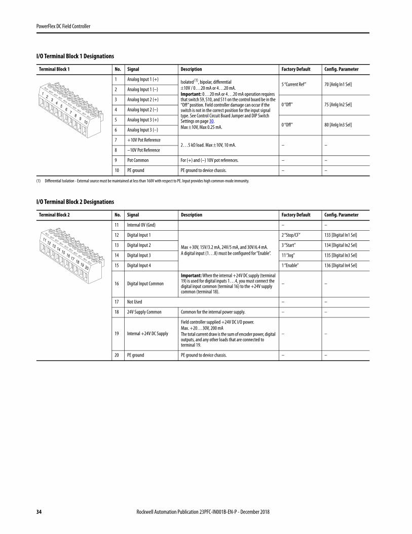
I/O Terminal Block 1 Designations
Terminal Block 1 No. Signal Description Factory Default Config. Parameter
1 Analog Input 1 (+) Isolated (1), bipolar, differential10V / 0…20 mA or 4…20 mA.Important: 0…20 mA or 4…20 mA operation requires that switch S9, S10, and S11 on the control board be in the “Off” position. Field controller damage can occur if the switch is not in the correct position for the input signal type. See Control Circuit Board Jumper and DIP Switch Settings on page 30.Max 10V, Max 0.25 mA.
(1) Differential Isolation - External source must be maintained at less than 160V with respect to PE. Input provides high common-mode immunity.
5 “Current Ref” 70 [Anlg In1 Sel]2 Analog Input 1 (–)
3 Analog Input 2 (+)0 “Off” 75 [Anlg In2 Sel]
4 Analog Input 2 (–)
5 Analog Input 3 (+)0 “Off” 80 [Anlg In3 Sel]
6 Analog Input 3 (–)
7 +10V Pot Reference2…5 kΩ load. Max 10V, 10 mA. – –
8 –10V Pot Reference
9 Pot Common For (+) and (–) 10V pot references. – –
10 PE ground PE ground to device chassis. – –
I/O Terminal Block 2 Designations
Terminal Block 2 No. Signal Description Factory Default Config. Parameter
11 Internal 0V (Gnd) – –
12 Digital Input 1
Max +30V, 15V/3.2 mA, 24V/5 mA, and 30V/6.4 mA.A digital input (1…8) must be configured for “Enable”.
2 “Stop/CF” 133 [Digital In1 Sel]
13 Digital Input 2 3 “Start” 134 [Digital In2 Sel]
14 Digital Input 3 11 “Jog” 135 [Digital In3 Sel]
15 Digital Input 4 1 “Enable” 136 [Digital In4 Sel]
16 Digital Input Common
Important: When the internal +24V DC supply (terminal 19) is used for digital inputs 1…4, you must connect the digital input common (terminal 16) to the +24V supply common (terminal 18).
– –
17 Not Used – –
18 24V Supply Common Common for the internal power supply. – –
19 Internal +24V DC Supply
Field controller supplied +24V DC I/O power.Max. +20…30V, 200 mAThe total current draw is the sum of encoder power, digital outputs, and any other loads that are connected to terminal 19.
– –
20 PE ground PE ground to device chassis. – –
23
45
1
78
910
6
12 13 14 15
11
17 18 19 20
16
34 Rockwell Automation Publication 23PFC-IN001B-EN-P - December 2018

PowerFlex DC Field Controller
I/O Terminal Block 3 Designations
Terminal Block 3 No. Signal DescriptionFactoryDefault
Config. Parameter
21 Analog Output 1 (+)
Max. 10V, 5 mA.
12 “Volt Fbk” 66 [Anlg Out1 Sel]22 Analog Output 1 (–)
23 Analog Output 2 (+)13 “Output Curr” 67 [Anlg Out2 Sel]
24 Analog Output 2 (–)
25 Digital Output Common – –
26 Digital Output 1
Max. +30V, 50 mA
5 “Ready” 145 [Digital Out1 Sel]
27 Digital Output 2 9 “Fault” 146 [Digital Out2 Sel]
28 Digital Output 3 2 “Vlt Thresh” 147 [Digital Out3 Sel]
29 Digital Output 4 4 “CurrentLimit” 148 [Digital Out4 Sel]
30 Digital Output +24V DC Source
Tie point for the internal supply or customer supplied voltage for the digital outputs. See theDigital and Analog I/O Wiring Examples for sourcing digital outputs on page 36 for more information.Max. +30V DC, 80 mA.Important: When the internal +24V DC supply (terminal 19) is used for digital outputs 1…4, you must connect terminal 19 to terminal 30 and the digital output common (terminal 25) to the +24V supply common (terminal 18).
– –
I/O Terminal Block 4 Designations
Terminal Block 4 No. Signal Description Factory Default Config. Parameter
31 Digital Input 5
Max +30V, 15V/3.2 mA, 24V/5 mA, and 30V/6.4 mA.A digital input (1…8) must be configured for “Enable”.
17 “Volt Sel 1” 137 [Digital In5 Sel]
32 Digital Input 6 18 “Volt Sel 2” 138 [Digital In6 Sel]
33 Digital Input 7 19 “Volt Sel 3” 139 [Digital In7 Sel]
34 Digital Input 8 31 “Contactor” 140 [Digital In8 Sel]
35 Digital Input Common
Important: When the internal +24V DC supply (terminal 19) is used for digital inputs 5…8, you must connect the digital input common (terminal 35) to the +24V supply common (terminal 18).
– –
36…40
Not Used – –
22 23 24 25
21
27 28 29 30
26
32 33 34 35
31
37 38 39 40
36
Rockwell Automation Publication 23PFC-IN001B-EN-P - December 2018 35

PowerFlex DC Field Controller
Digital I/O Connections for PowerFlex DC Drive or SAR Interface with a Field Controller
The PowerFlex DC drive or SAR and field controller are connected using digital and analog I/O as shown in this illustration and by making these connections:
• Connect terminal 25 (TB3 - I/O common) on the PowerFlex DC Field Controller to terminal 25 (TB3 - I/O common) on the PowerFlex DC drive.
• Connect terminal 19 (TB2 - internal 24V DC supply) to terminal 30 (TB3 - digital output +24V DC source) on the PowerFlex DC Field Controller.
PowerFlex DC Drive to PowerFlex DC Field Controller I/O Connections
Digital and Analog I/O Wiring Examples
Input/output Connection Example Required Parameter Changes
Potentiometer Unipolar Reference10 kΩ Pot. Recommended(2 kΩ Minimum)
• Adjust Scaling:Configure for Voltage or Current: 71 [Anlg In1 Config]72 [Anlg In1 Scale] and73 [Anlg1 Tune Scale]
• View Signal Value:1404 [Analog In1 Value]
• View Signal Output:385 [Volt Ref Out]
Verify that DIP switch S9 is set to “On” (0…10V). See Control Circuit Board Jumper and DIP Switch Settings on page 30.
DigitalOutputs
“Fld Curr Ref ”(36)
“FC Fdbk” (26)
“Wired FC Act” (75) “Wired FC Act” (34)
“Current Ref” (5)
“Output Curr” (13) or “Filtered Cur” (29)
“Wired FC Inv” (33)“Wired FC En” (32)
“Wired FC Inv” (74)“Wired FC En” (73)
PowerFlex DC Drive PowerFlex DC Field Controller
Par 469 [Field Mode Sel] =“Wired FC FW” (4) or“Wired FC BS” (6) P241 [Vlt Cur Mode Sel] = “Curr Reg” (2)
C
VoltageClamp
DC DA1
A2
M
DigitalInputs
Pars 133...144 [Digital Inx Sel] Pars 145...152 [Digital Outx Sel]
Pars 70, 75, 80 [Anlg Inx Sel] Pars 66...69 [Anlg Outx Sel]
AnalogOutput
Pars 66...69 [Anlg Outx Sel]AnalogInput
Pars 70, 75, 80 [Anlg Inx Sel]
AnalogInput
AnalogOutput
1
2
3
4
5
6
7
8
9
10
36 Rockwell Automation Publication 23PFC-IN001B-EN-P - December 2018

PowerFlex DC Field Controller
Analog Input Unipolar Reference0…10V Input, or0…20 mA or 4…20 mA
• Configure for Voltage or Current:71 [Anlg In1 Config]
• Adjust Scaling:72 [Anlg In1 Scale] and73 [Anlg1 Tune Scale]
• View Signal Value:1404 [Analog In1 Value]
• View Signal Output:385 [Volt Ref Out]
Verify that DIP switch S9 is set to “On” for 0…10V operation, or “Off” for 0…20 mA or 4…20 mA operation. See Control Circuit Board Jumper and DIP Switch Settings on page 30.
Analog Output Bipolar Signal10V Bipolar (based on the signal of the assigned input source - for example Analog Input 1), or0…10V Unipolar (shown)
• Select Source Value:66 [Anlg Out1 Sel]
• Adjust Scaling:62 [Anlg Out1 Scale]
Enable Input24V DC internal supply
• No Changes Required.
If the digital input used for “Enable” is changed from the default setting of digital input 4, the wiring must be changed accordingly.
2-Wire Control Non-Reversing24V DC internal supply
Important: Programming inputs for 2-wire control deactivates the HIM Start and Jog buttons.
• Disable Digital Input 1:133 [Digital In1 Sel]= 0 “Not Used”
• Set Digital Input 2:134 [Digital In2 Sel]= 5 “Run”
2-Wire ControlReversing24V DC external supply
Important: Programming inputs for 2-wire control deactivates the HIM Start and Jog buttons.
• Set Digital Input 1:133 [Digital In1 Sel]= 6 “Run Forward”
• Set Digital Input 2:134 [Digital In2 Sel]= 7 “Run Reverse”
Digital and Analog I/O Wiring Examples (continued)
Input/output Connection Example Required Parameter Changes
Common+ 1
2
3
4
5
6
7
8
9
10
21
22
23
24
25
26
27
28
29
30
+–
11
12
13
14
15
16
17
18
19
20
11
12
13
14
15
16
17
18
19
20
Stop-Run
Run Rev.
Run Fwd.
+24V Neutral/Common
11
12
13
14
15
16
17
18
19
20
Rockwell Automation Publication 23PFC-IN001B-EN-P - December 2018 37

PowerFlex DC Field Controller
3-Wire Control24V DC internal supply
• No Changes Required.
3-Wire Control24V DC external supplyRequires 3-wire functions only ([Digital In1 Sel]). Configuring2-wire selections cause a type 2 alarm.
• No Changes Required
Sourcing Digital OutputsInternal 24V DC supply
• No Changes Required
Sourcing Digital OutputsExternal 24V DC supply
• No Changes Required
Digital and Analog I/O Wiring Examples (continued)
Input/output Connection Example Required Parameter Changes
11
12
13
14
15
16
17
18
19
20
Stop
Start
11
12
13
14
15
16
17
18
19
20
Stop
Start
+24V Neutral/Common
21
22
23
24
25
26
27
28
29
30
Ready
Fault
Vlt Thresh
11
12
13
14
15
16
17
18
19
20
21
22
23
24
25
26
27
28
29
30
Ready
Fault
External+24V DC
ExternalNeutral/
Common
Vlt Thresh
38 Rockwell Automation Publication 23PFC-IN001B-EN-P - December 2018

PowerFlex DC Field Controller
Install the Protective Covers and Route I/O and Control Wires
Install the protective covers on the field controller. See Remove the Covers on page 12. Route all I/O and control wires from the bottom of the field controller, between the lower front cover and the terminal cover.
Connect the Human Interface ModuleThe human interface module (HIM) is ordered separately. See the PowerFlex Digital DC Drive Technical Data, 20P-TD001, for more information on HIM options and catalog numbers.
The PowerFlex DC Field Controller provides these HIM cable connection points (frame A shown).
ATTENTION: Do not operate the field controller with the protective covers removed. Operation with the protective covers removed can result in a hazardous condition that could cause personal injury and/or equipment damage.
No. Connector Description
1 DPI Port 1 HIM connection when installed in cover.
2 DPI Port 2 DPI cable connection for hand-held and remote options.
3 DPI Port 3 or 2 Splitter cable that is connected to DPI Port 2 provides additional port.
4 DPI Port 5 Cable connection for communication adapter (shown with front cover removed).
Frame A Shown
2
1or3
STS
PORT
MOD
NET A
NET B
1 4
2
3
Rockwell Automation Publication 23PFC-IN001B-EN-P - December 2018 39

PowerFlex DC Field Controller
Remove and Install the HIMThe HIM can be removed or installed while the field controller is powered.
Additional ResourcesThese documents contain additional information concerning related products from Rockwell Automation.
You can view or download publications athttp://www.rockwellautomation.com/global/literature-library/overview.page. To order paper copies of technical documentation, contact your local Allen-Bradley distributor or Rockwell Automation sales representative.
IMPORTANT HIM removal is only permissible in Auto mode. If the HIM is removed while in Manual mode or the HIM is the only remaining control device, a fault occurs. See the PowerFlex DC Field Controller Programming Manual, publication 20PFC-PM001, for more information on how to use the HIM and fault and alarm indications.
Step Example Display
To remove the HIM, follow these steps.
1. Press and then (Remove). The ‘Remove HIM’ confirmation screen appears.
2. To confirm that you want to remove the HIM, press .
3. Remove the HIM from the cradle on the field controller.
4. To install the HIM, insert it into the cradle on the field controller or connect the DPI cable.
Resource Description
PowerFlex Digital DC Drive Technical Data, publication 20P-TD001
Provides detailed information on:• Basic product selection• Field controller specifications• Option specifications• Circuit protection
PowerFlex DC Fiber-optic Interface Option Module Installation Instructions, publication 20P-IN078 Provides installation instructions for the PowerFlex DC fiber-optic interface module.
PowerFlex DC Field Controller Voltage Clamp Installation Instructions, publication23PFC-IN002 Provides Installation Instructions for the PowerFlex DC controller voltage clamp installation instructions.
PowerFlex DC Field Controller Programming Manual, publication 23PFC-PM001 Provides information on how to start up, program, and troubleshoot the PowerFlex DC Field Controller.
PowerFlex Digital DC Drive - Frame A Hardware Service Manual, publication 20P-TG001 Provides hardware test procedures and spare parts replacement instructions for Frame A PowerFlex DC drives and field controllers.
PowerFlex Digital DC Drive - Frame B Hardware Service Manual, publication 20P-TG002 Provides hardware test procedures and spare parts replacement instructions for Frame B PowerFlex DC drives and field controllers.
Industrial Automation Wiring and Grounding Guidelines, publication 1770-4.1 Provides general guidelines for installing a Rockwell Automation industrial system.
Product Certifications website, http://www.rockwellautomation.com/global/certification/overview.page Provides declarations of conformity, certificates, and other certification details.
ALTRemove Op Intrfc:Press Enter to Disconnect Op Intrfc?(Port 1 Control)
40 Rockwell Automation Publication 23PFC-IN001B-EN-P - December 2018

PowerFlex DC Field Controller
Notes:
Rockwell Automation Publication 23PFC-IN001B-EN-P - December 2018 41

Rockwell Automation SupportUse the following resources to access support information.
Documentation FeedbackYour comments will help us serve your documentation needs better. If you have any suggestions on how to improve this document, complete the How Are We Doing? form at http://literature.rockwellautomation.com/idc/groups/literature/documents/du/ra-du002_-en-e.pdf.
Technical Support Center Knowledgebase Articles, How-to Videos, FAQs, Chat, User Forums, and Product Notification Updates. https://rockwellautomation.custhelp.com/
Local Technical Support Phone Numbers Locate the phone number for your country. http://www.rockwellautomation.com/global/support/get-support-now.page
Direct Dial Codes Find the Direct Dial Code for your product. Use the code to route your call directly to a technical support engineer. http://www.rockwellautomation.com/global/support/direct-dial.page
Literature Library Installation Instructions, Manuals, Brochures, and Technical Data. http://www.rockwellautomation.com/global/literature-library/overview.page
Product Compatibility and Download Center (PCDC)
Get help determining how products interact, check features and capabilities, and find associated firmware. http://www.rockwellautomation.com/global/support/pcdc.page
Allen-Bradley, PowerFlex, Rockwell Automation, and Rockwell Software are trademarks of Rockwell Automation, Inc.
Trademarks not belonging to Rockwell Automation are property of their respective companies.
Rockwell Otomasyon Ticaret A.Ş., Kar Plaza İş Merkezi E Blok Kat:6 34752 İçerenköy, İstanbul, Tel: +90 (216) 5698400
Rockwell Automation maintains current product environmental information on its website athttp://www.rockwellautomation.com/rockwellautomation/about-us/sustainability-ethics/product-environmental-compliance.page.
At the end of its life, collect this equipment separately from any unsorted municipal waste.
Publication 23PFC-IN001B-EN-P - December 2018 Supersedes Publication 23PFC-IN001A-EN-P November 2017 Copyright © 2018 Rockwell Automation, Inc. All rights reserved. Printed in the U.S.A.
waste
Top Related