


Languages
Pages
Legal

1
Information Network 1
Routing (1)
Youki Kadobayashi
NAIST
©2013 Suguru Yamaguchi and Youki Kadobayashi, All rights reserved.
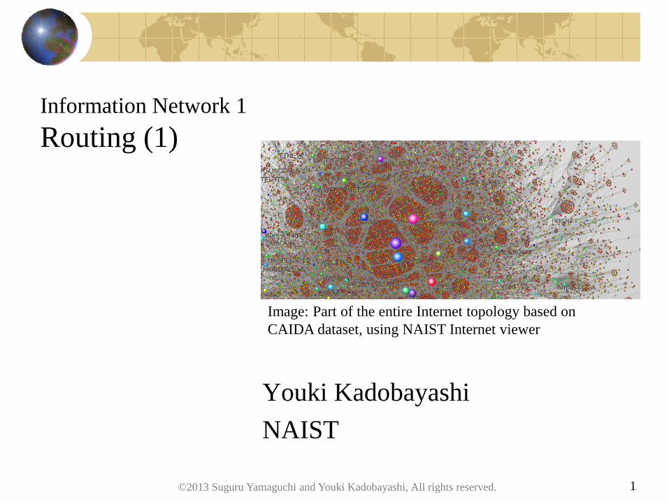
Image: Part of the entire Internet topology based on
CAIDA dataset, using NAIST Internet viewer

2
The Routing Problem
How do I get from source to destination?
Which path is best? In terms of:
Number of hops
Delay, bandwidth
Policy constraints, cost…
Who will make decision?
Router?
Source?
How can we detect failures?
How much the overhead will be?
S D
©2013 Suguru Yamaguchi and Youki Kadobayashi, All rights reserved.
3
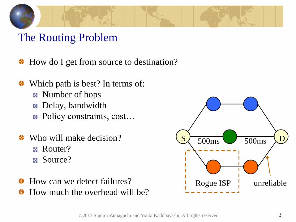
The Routing Problem
How do I get from source to destination?
Which path is best? In terms of:
Number of hops
Delay, bandwidth
Policy constraints, cost…
Who will make decision?
Router?
Source?
How can we detect failures?
How much the overhead will be?
S D
Rogue ISP
500ms 500ms
unreliable
©2013 Suguru Yamaguchi and Youki Kadobayashi, All rights reserved.

Solution design space for the routing problem
Represent network in:
a graph, or
a matrix
Collect information:
across the network, or
toward some routers, or
only locally among neighbors
Compute route at:
every router, or
some routers
… solutions are instantiated in routing systems.
4 ©2013 Suguru Yamaguchi and Youki Kadobayashi, All rights reserved.
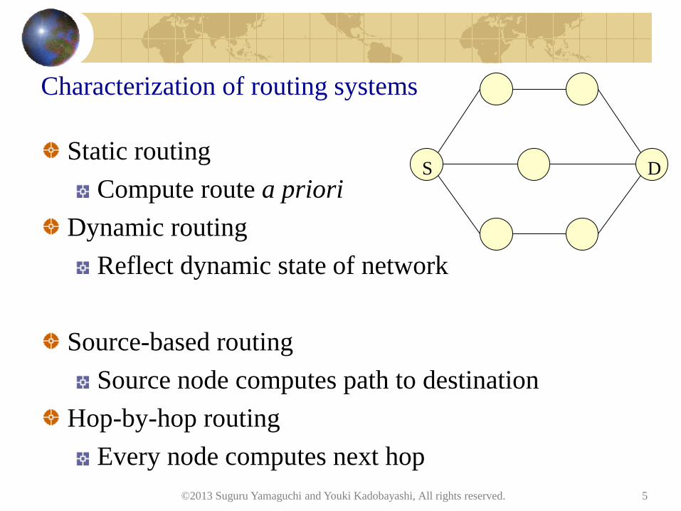
Characterization of routing systems
Static routing
Compute route a priori
Dynamic routing
Reflect dynamic state of network
Source-based routing
Source node computes path to destination
Hop-by-hop routing
Every node computes next hop
5
S D
©2013 Suguru Yamaguchi and Youki Kadobayashi, All rights reserved.
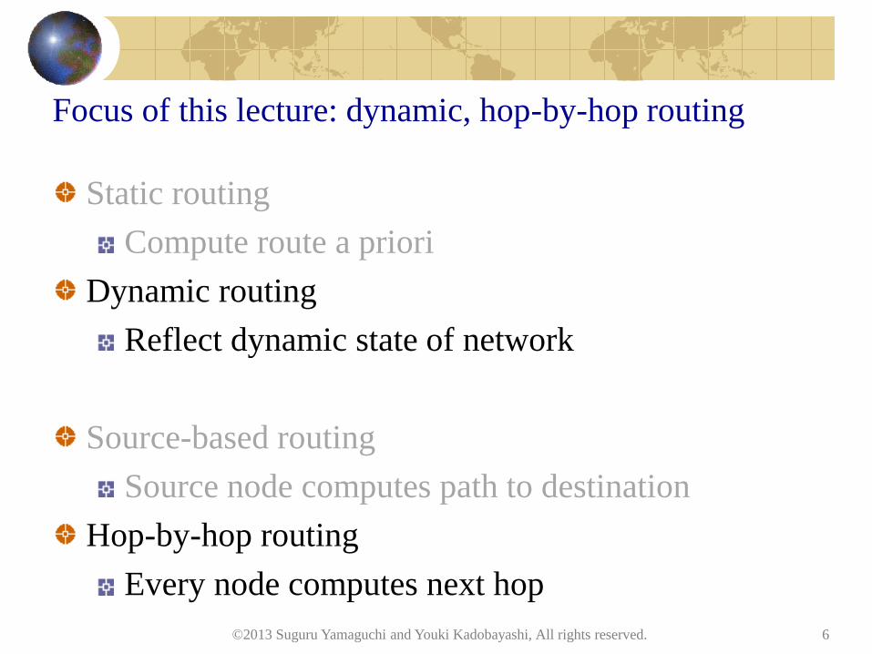
Focus of this lecture: dynamic, hop-by-hop routing
Static routing
Compute route a priori
Dynamic routing
Reflect dynamic state of network
Source-based routing
Source node computes path to destination
Hop-by-hop routing
Every node computes next hop
6 ©2013 Suguru Yamaguchi and Youki Kadobayashi, All rights reserved.
7
Routing system: its function
Provision end-to-end reachability
Automatically compute best path
Distribute traffic among multiple links
Avoid failing links
Isolate faults
Reflect administrative policies
… in one system. Isn’t it awesome.
©2013 Suguru Yamaguchi and Youki Kadobayashi, All rights reserved.
Routing system characterization
Representation of network
Network topology
Attributes associated with each link
Exchange of information
Communication overhead
Propagation speed
Computation algorithm
Computation overhead
Convergence speed
Routing system: protocol + information + algorithm
8 ©2013 Suguru Yamaguchi and Youki Kadobayashi, All rights reserved.
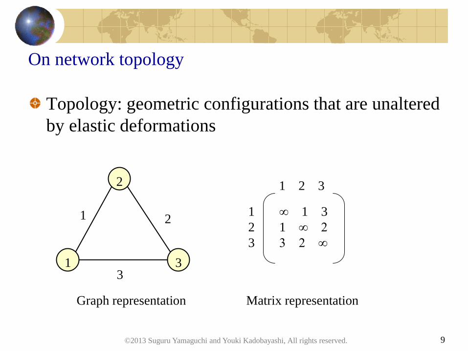
On network topology
Topology: geometric configurations that are unaltered
by elastic deformations
9
1
2
3
1
3
2
1 2 3
1
2
3
∞ 1 3
1 ∞ 2
3 2 ∞
Graph representation Matrix representation
©2013 Suguru Yamaguchi and Youki Kadobayashi, All rights reserved.
10
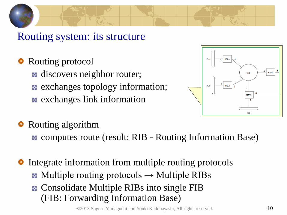
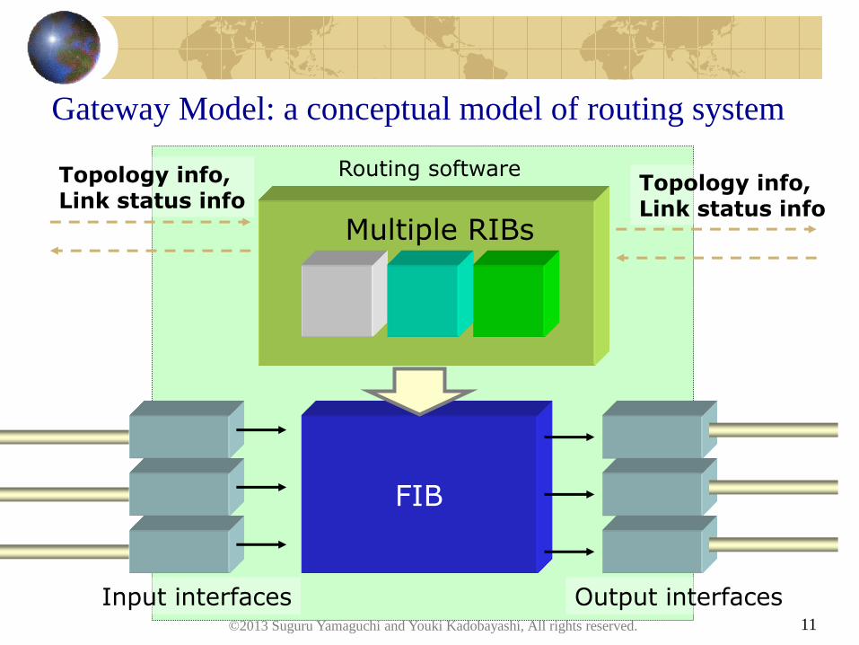
Routing system: its structure
Routing protocol
discovers neighbor router;
exchanges topology information;
exchanges link information
Routing algorithm
computes route (result: RIB - Routing Information Base)
Integrate information from multiple routing protocols
Multiple routing protocols → Multiple RIBs
Consolidate Multiple RIBs into single FIB (FIB: Forwarding Information Base)
©2013 Suguru Yamaguchi and Youki Kadobayashi, All rights reserved.
11
Gateway Model: a conceptual model of routing system
FIB
Input interfaces Output interfaces
Multiple RIBs
Routing software Topology info, Link status info
Topology info, Link status info
©2013 Suguru Yamaguchi and Youki Kadobayashi, All rights reserved.
12
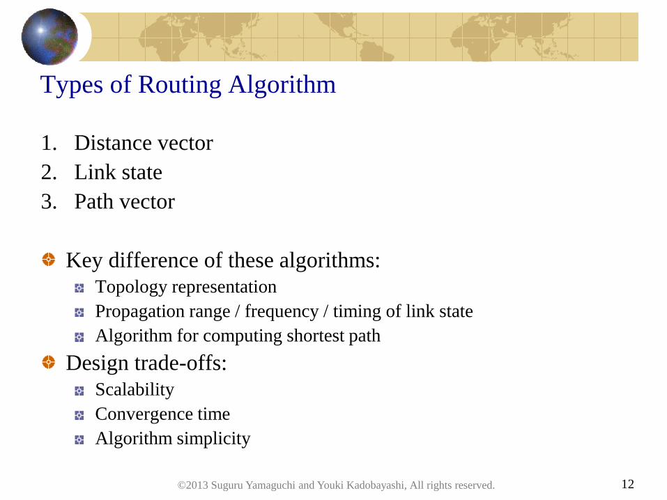
Types of Routing Algorithm
1. Distance vector
2. Link state
3. Path vector
Key difference of these algorithms:
Topology representation
Propagation range / frequency / timing of link state
Algorithm for computing shortest path
Design trade-offs:
Scalability
Convergence time
Algorithm simplicity
©2013 Suguru Yamaguchi and Youki Kadobayashi, All rights reserved.

13
Questions?
©2013 Suguru Yamaguchi and Youki Kadobayashi, All rights reserved.
Distance Vector Routing
©2013 Suguru Yamaguchi and Youki Kadobayashi, All rights reserved. 14

15
Distance vector routing w/ Bellman-Ford algorithm
1. assign distance vector to myself 0; for others, assign ∞
2. send my distance vectors to all neighbor routers
3. router calculates minimum distance vectors by 1) distance vectors advertised by neighbor routers and 2) distance from myself to individual neighbor router
Initial condition bi
(0) ← ∞ (i ≠ D)
bD(0) ← 0
Repetition
bi(m) ← minj ∈ Vi{bj
(m-1) + dij}
Terminal condition bi
(m) = bi(m-1)
D: destination router, bi(m): distance between router “i” and “D” by m-times iterative
calculation, Vi: neighbor routers of router “i”, dij: distance of link between router “i” and j
DN p.397
©2013 Suguru Yamaguchi and Youki Kadobayashi, All rights reserved.
16
RIP: Routing Information Protocol
Distance vector routing
RIP-2 (IPv4), RIPng (IPv6)
Used in relatively small network
• Due to ease of implementation and operation
Textbook classics
RFC 2453, RFC 2080
©2013 Suguru Yamaguchi and Youki Kadobayashi, All rights reserved.
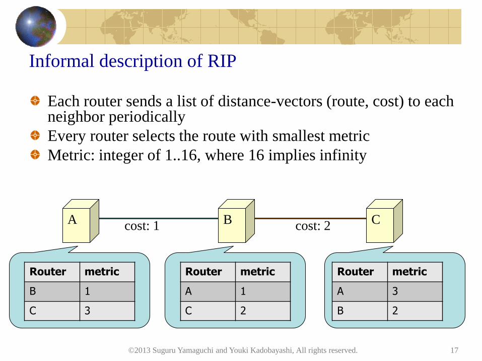
Informal description of RIP
Each router sends a list of distance-vectors (route, cost) to each neighbor periodically
Every router selects the route with smallest metric
Metric: integer of 1..16, where 16 implies infinity
©2013 Suguru Yamaguchi and Youki Kadobayashi, All rights reserved. 17
A B C cost: 2 cost: 1
Router metric
A 3
B 2
Router metric
A 1
C 2
Router metric
B 1
C 3

Hands on: see how RIP works
(description of GNS3)
(basic instruction to keep RIP up and running)
©2013 Suguru Yamaguchi and Youki Kadobayashi, All rights reserved. 18
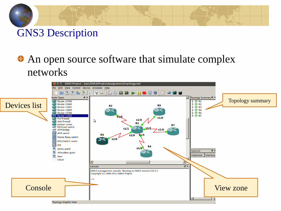
GNS3 Description
An open source software that simulate complex
networks
Devices list
View zone
Topology summary
Console
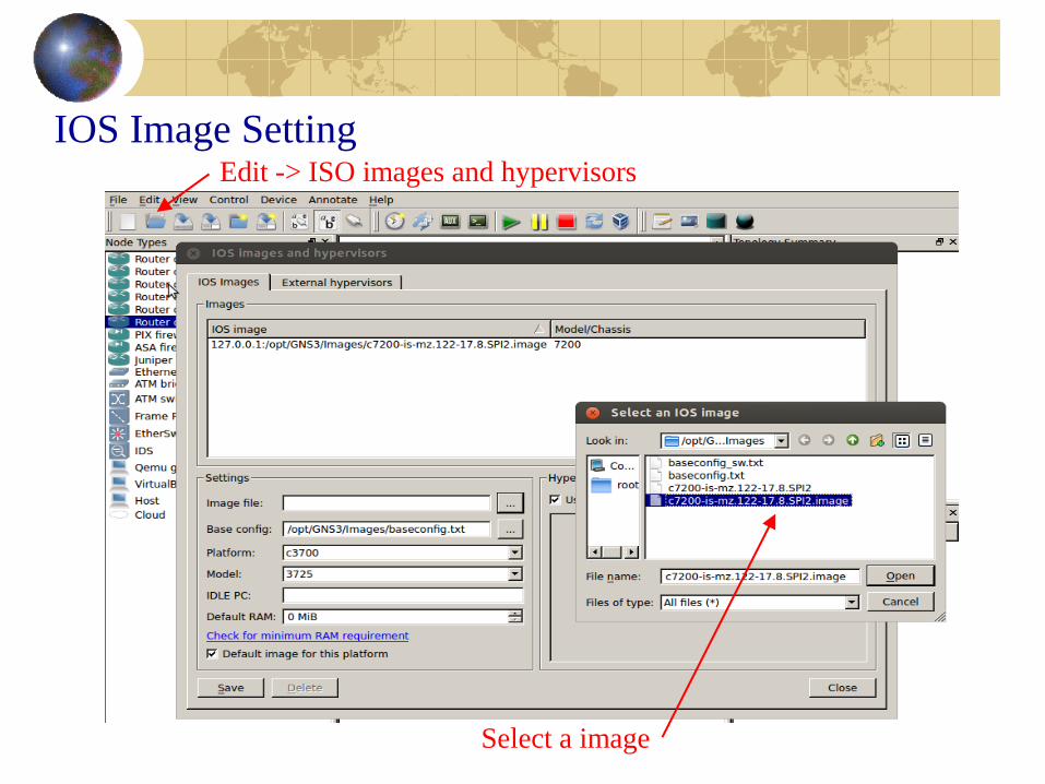
IOS Image Setting Edit -> ISO images and hypervisors
Select a image

Cisco Router: Basic Configuration
• enable
• configure terminal
• interface name_of_the_inteface
• ip address ip_address mask
• no shutdown
• show ip interface brief
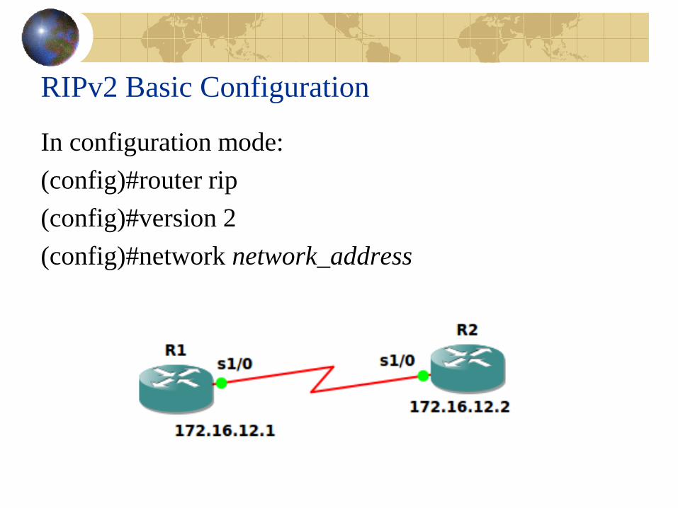
RIPv2 Basic Configuration
In configuration mode:
(config)#router rip
(config)#version 2
(config)#network network_address
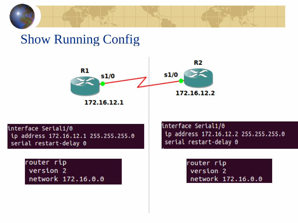
Show Running Config
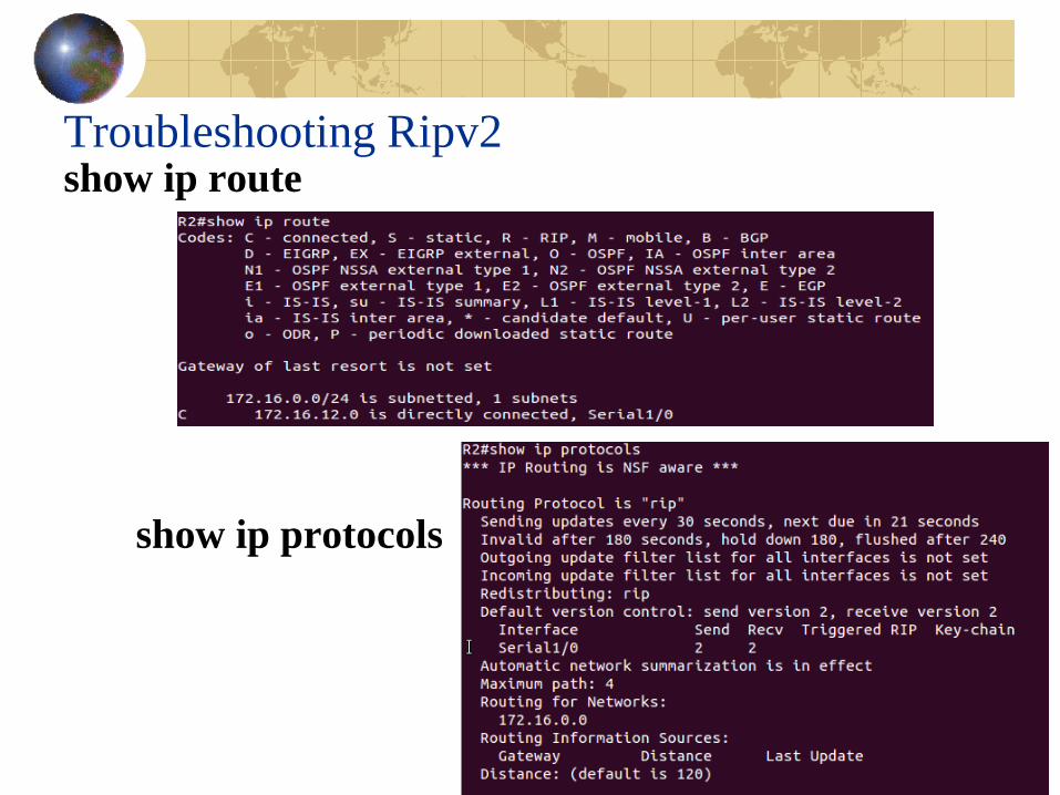
Troubleshooting Ripv2 show ip route
show ip protocols
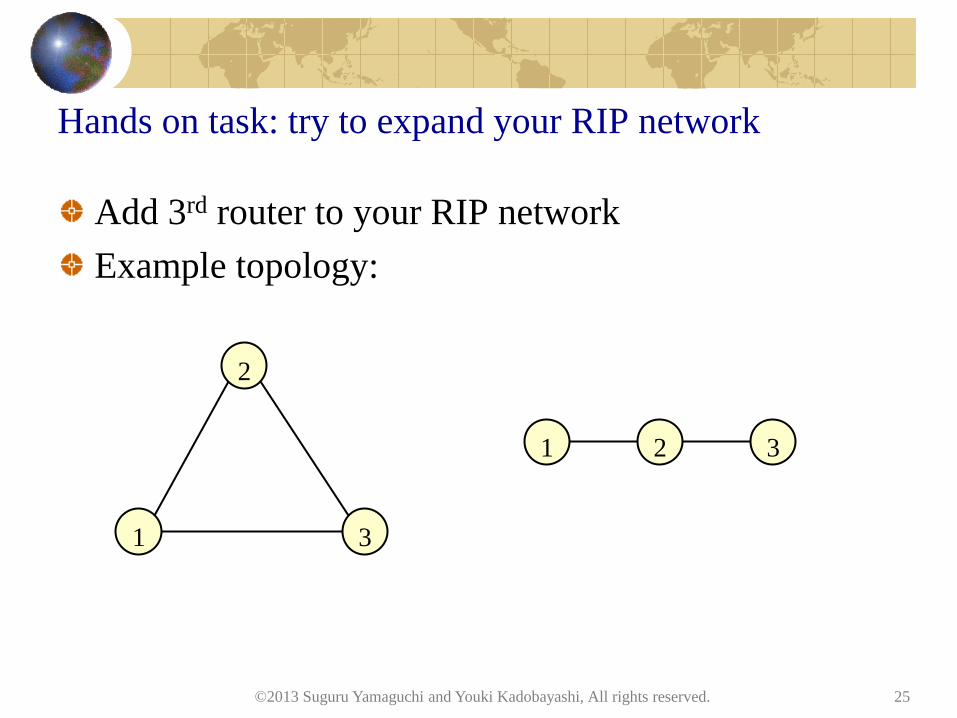
Hands on task: try to expand your RIP network
Add 3rd router to your RIP network
Example topology:
©2013 Suguru Yamaguchi and Youki Kadobayashi, All rights reserved. 25
1
2
3
1 3 2

Adding A New Router
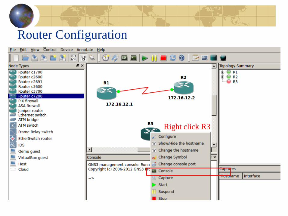
Router Configuration
Right click R3
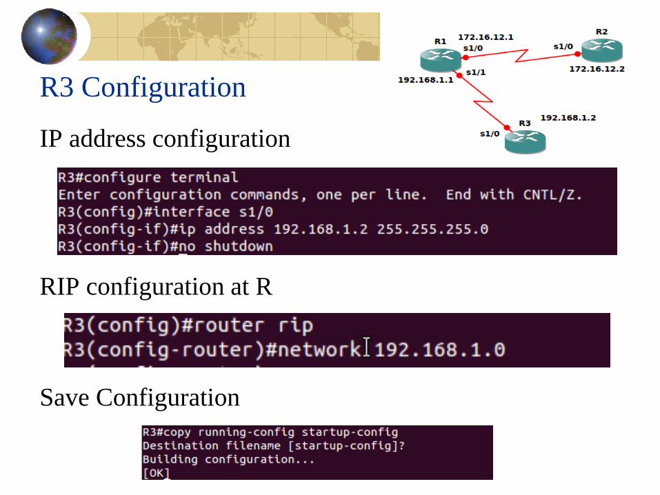
R3 Configuration
IP address configuration
RIP configuration at R
Save Configuration
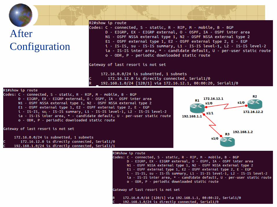
After
Configuration
30
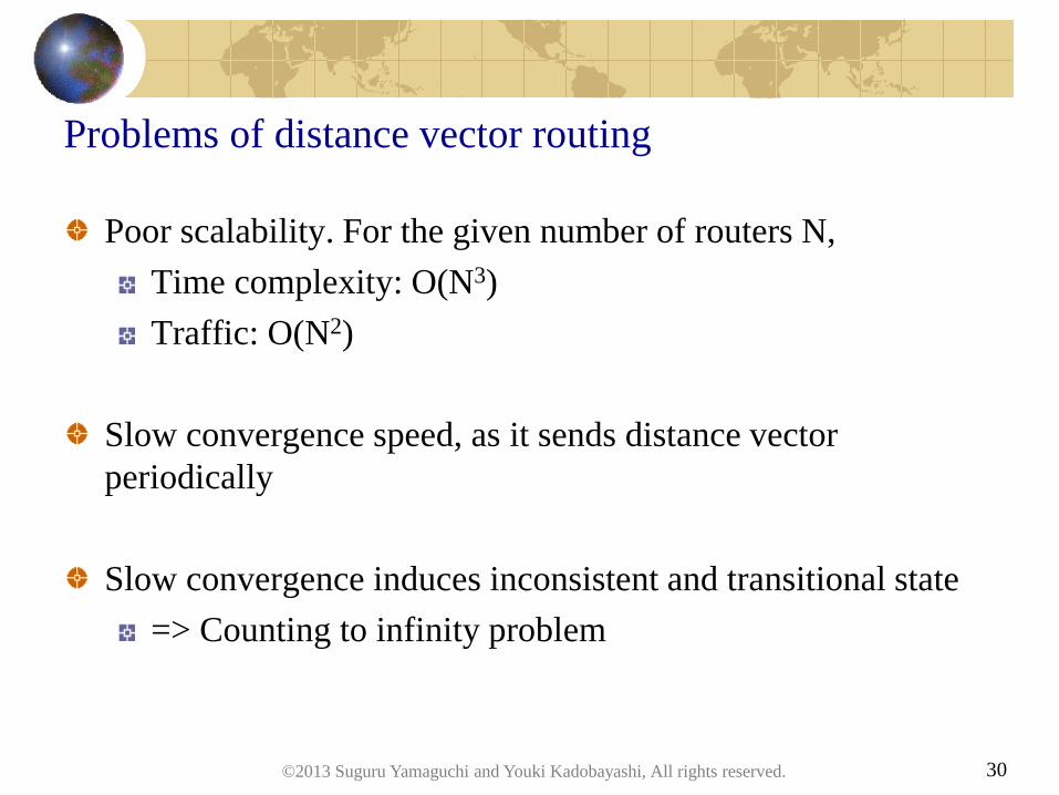
Problems of distance vector routing
Poor scalability. For the given number of routers N,
Time complexity: O(N3)
Traffic: O(N2)
Slow convergence speed, as it sends distance vector
periodically
Slow convergence induces inconsistent and transitional state
=> Counting to infinity problem
©2013 Suguru Yamaguchi and Youki Kadobayashi, All rights reserved.
31
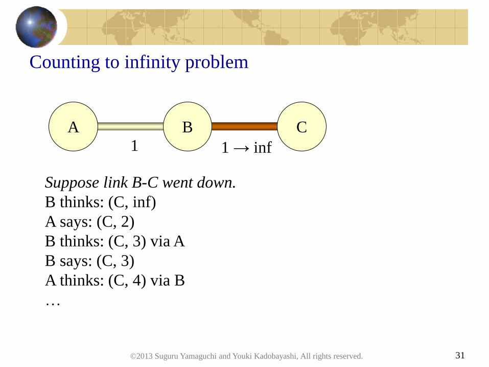
Counting to infinity problem
A C B
Suppose link B-C went down.
B thinks: (C, inf)
A says: (C, 2)
B thinks: (C, 3) via A
B says: (C, 3)
A thinks: (C, 4) via B
…
1 1 → inf
©2013 Suguru Yamaguchi and Youki Kadobayashi, All rights reserved.
32
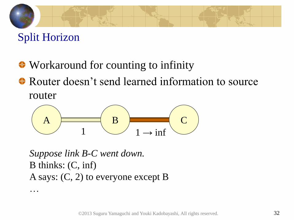
Split Horizon
A C B
Suppose link B-C went down.
B thinks: (C, inf)
A says: (C, 2) to everyone except B
…
1 1 → inf
Workaround for counting to infinity
Router doesn’t send learned information to source
router
©2013 Suguru Yamaguchi and Youki Kadobayashi, All rights reserved.
33
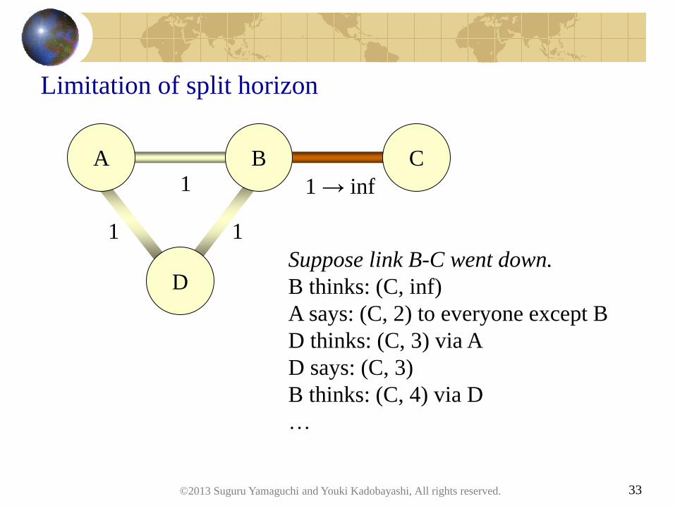
Limitation of split horizon
A C B
Suppose link B-C went down.
B thinks: (C, inf)
A says: (C, 2) to everyone except B
D thinks: (C, 3) via A
D says: (C, 3)
B thinks: (C, 4) via D
…
1 1 → inf
D
1 1
©2013 Suguru Yamaguchi and Youki Kadobayashi, All rights reserved.
34
Questions?
(Dumb questions welcomed while you’re a student)
Extra hands-on if you are further motivated:
Introduce link failure and observe counting-to-
infinity problem
Add 4th router as in the last slide and observe that
split-horizon does not save us
©2013 Suguru Yamaguchi and Youki Kadobayashi, All rights reserved.
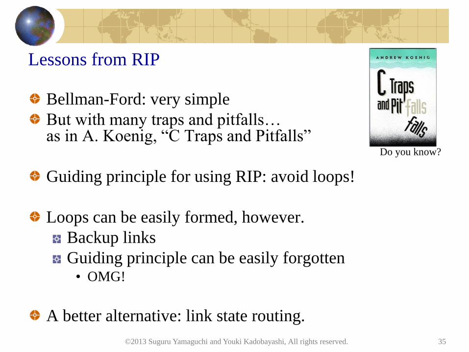
Lessons from RIP
Bellman-Ford: very simple
But with many traps and pitfalls… as in A. Koenig, “C Traps and Pitfalls”
Guiding principle for using RIP: avoid loops!
Loops can be easily formed, however.
Backup links
Guiding principle can be easily forgotten • OMG!
A better alternative: link state routing.
©2013 Suguru Yamaguchi and Youki Kadobayashi, All rights reserved. 35
Do you know?
Link-State Routing
©2013 Suguru Yamaguchi and Youki Kadobayashi, All rights reserved. 36
37
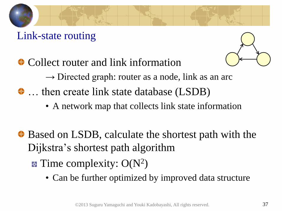
Link-state routing
Collect router and link information
→ Directed graph: router as a node, link as an arc
… then create link state database (LSDB)
• A network map that collects link state information
Based on LSDB, calculate the shortest path with the
Dijkstra’s shortest path algorithm
Time complexity: O(N2)
• Can be further optimized by improved data structure
©2013 Suguru Yamaguchi and Youki Kadobayashi, All rights reserved.
38
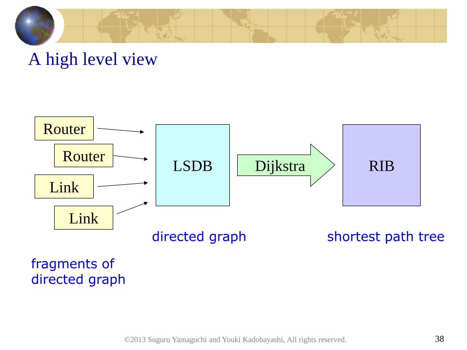
A high level view
Router
Link
Router
Link
LSDB RIB Dijkstra
directed graph shortest path tree
fragments of directed graph
©2013 Suguru Yamaguchi and Youki Kadobayashi, All rights reserved.
39
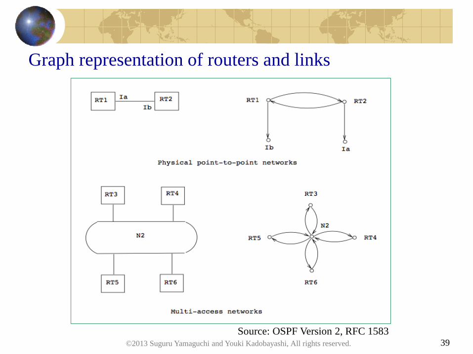
Graph representation of routers and links
Source: OSPF Version 2, RFC 1583 ©2013 Suguru Yamaguchi and Youki Kadobayashi, All rights reserved.
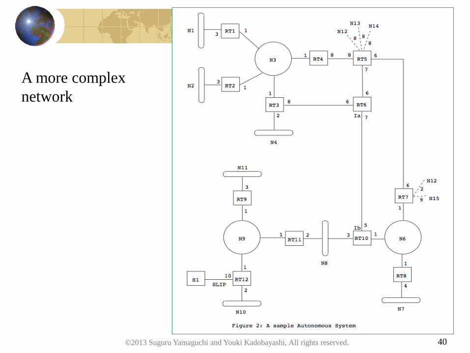
40
A more complex
network
©2013 Suguru Yamaguchi and Youki Kadobayashi, All rights reserved.
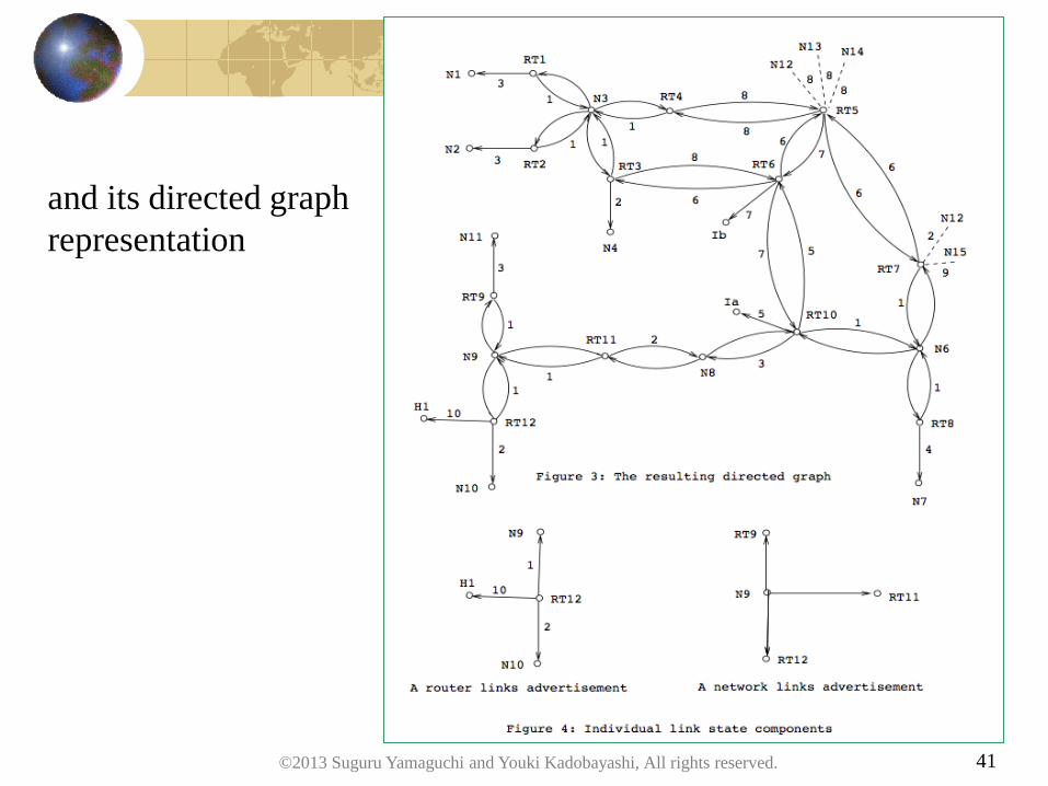
41
and its directed graph
representation
©2013 Suguru Yamaguchi and Youki Kadobayashi, All rights reserved.
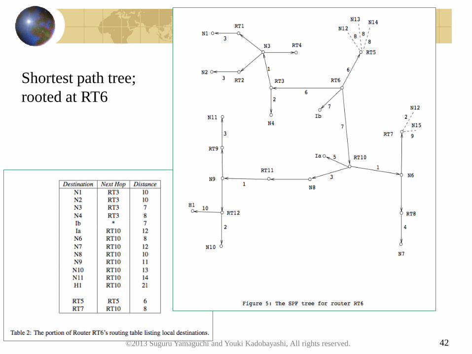
42
Shortest path tree;
rooted at RT6
©2013 Suguru Yamaguchi and Youki Kadobayashi, All rights reserved.

43
Questions?
©2013 Suguru Yamaguchi and Youki Kadobayashi, All rights reserved.
44
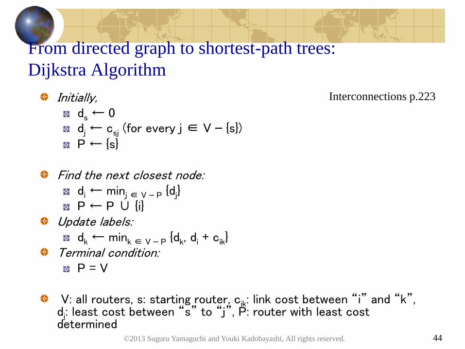
From directed graph to shortest-path trees:
Dijkstra Algorithm
Initially, ds ← 0 dj ← csj (for every j ∈ V – {s}) P ← {s}
Find the next closest node:
di ← minj ∈ V – P {dj} P ← P ∪ {i}
Update labels: dk ← mink ∈ V – P {dk, di + cik}
Terminal condition: P = V
V: all routers, s: starting router, cik: link cost between “i” and “k”, dj: least cost between “s” to “j”, P: router with least cost determined
©2013 Suguru Yamaguchi and Youki Kadobayashi, All rights reserved.
Interconnections p.223

45
Pros and Cons of Link-State Routing
Traffic increases in proportion to the number of links and
routers
Storage complexity increases in proportion to the number of
links and routers
Time complexity: lower than distance vector routing
Convergence time: must be short, for transient loop issue
Counting to infinity doesn’t happen
(read: fewer traps and pitfalls)
Flexible configuration of link cost is possible
(no nonsense like 16 = infinity)
©2013 Suguru Yamaguchi and Youki Kadobayashi, All rights reserved.
46
OSPF: Open Shortest Path First
The link state routing protocol for the Internet
OSPFv2 (IPv4), OSPFv3 (IPv6)
Functions
Recognize neighbor router
Exchange link state information and create LSDB
Calculate shortest path tree (spanning tree)
+ Designated Router, Backup Designated Router
+ Hierarchical structure by area
+ Collaboration with EGP
RFC 2328, 5340
©2013 Suguru Yamaguchi and Youki Kadobayashi, All rights reserved.
47
OSPF Hello
Discover neighbor router on the same link
• send Hello packet to 224.0.0.5, ff02::5 (AllSPFRouters)
List of neighbor routers in Hello packet
• check bidirectional communication
(select designated router and backup designated router)
Send Hello packet periodically to detect link down
keeps pinging, as in ICMP
©2013 Suguru Yamaguchi and Youki Kadobayashi, All rights reserved.
48
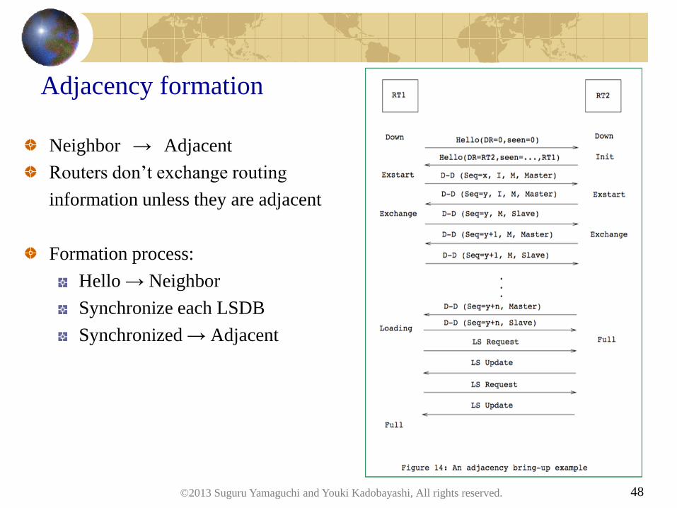
Adjacency formation
Neighbor → Adjacent
Routers don’t exchange routing
information unless they are adjacent
Formation process:
Hello → Neighbor
Synchronize each LSDB
Synchronized → Adjacent
©2013 Suguru Yamaguchi and Youki Kadobayashi, All rights reserved.

Hands on: say hello in OSPF!
(basic instruction to bring OSPF up and running)
(establish OSPF adjacency)
(add 1 or 2 routers)
©2013 Suguru Yamaguchi and Youki Kadobayashi, All rights reserved. 49
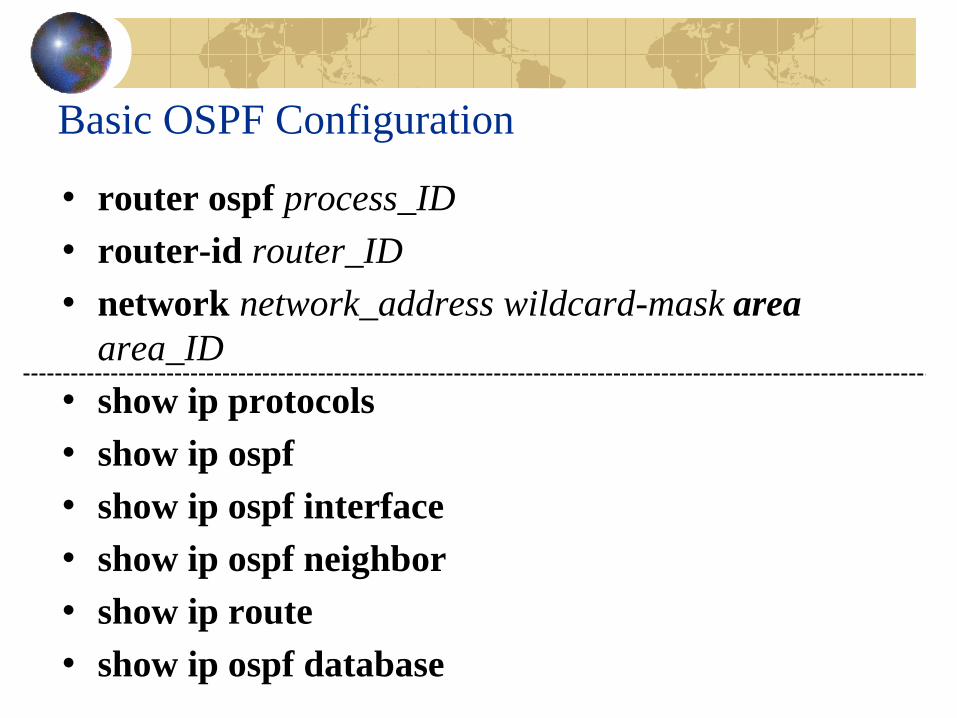
Basic OSPF Configuration
• router ospf process_ID
• router-id router_ID
• network network_address wildcard-mask area
area_ID
• show ip protocols
• show ip ospf
• show ip ospf interface
• show ip ospf neighbor
• show ip route
• show ip ospf database
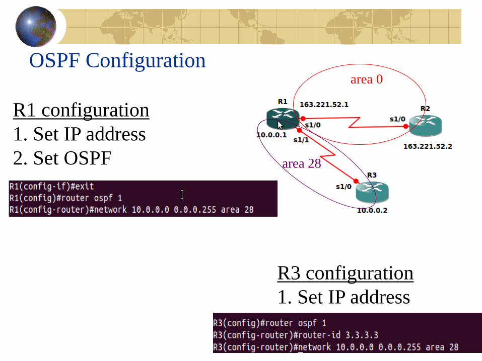
OSPF Configuration
R3 configuration
1. Set IP address
2. Set OSPF
R1 configuration
1. Set IP address
2. Set OSPF
area 0
area 28
52
Topology Representation in OSPF
LSA (Link State Advertisement)
• Type 1: Router LSA
• Type 2: Network LSA
• Type 3: Summary LSA (network)
• Type 4: Summary LSA (AS boundary)
• Type 5: AS External LSA
LSA common header
• Validity period and sequence number in LSA header
• Helps routers to tell if given LSA is fresh
©2013 Suguru Yamaguchi and Youki Kadobayashi, All rights reserved.

53
Questions?
©2013 Suguru Yamaguchi and Youki Kadobayashi, All rights reserved.

Summary
©2013 Suguru Yamaguchi and Youki Kadobayashi, All rights reserved. 54
55
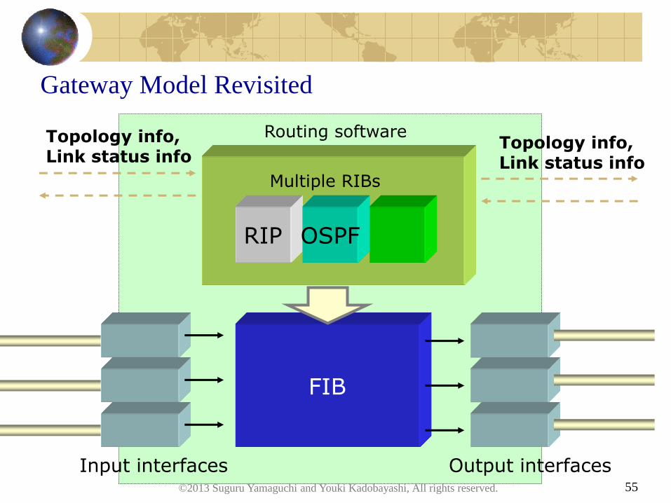
Gateway Model Revisited
FIB
Input interfaces Output interfaces
RIP
Multiple RIBs
OSPF
Routing software Topology info, Link status info
Topology info, Link status info
©2013 Suguru Yamaguchi and Youki Kadobayashi, All rights reserved.

56
Summary
Routing system: design space, characterization
Distance vector routing
Bellman-Ford algorithm
RIP protocol, information model
Traps and pitfalls
Link state routing
Graph and its spanning trees
Dijkstra algorithm
OSPF protocol, algorithm, information model
©2013 Suguru Yamaguchi and Youki Kadobayashi, All rights reserved.
Assignment
©2013 Suguru Yamaguchi and Youki Kadobayashi, All rights reserved. 57
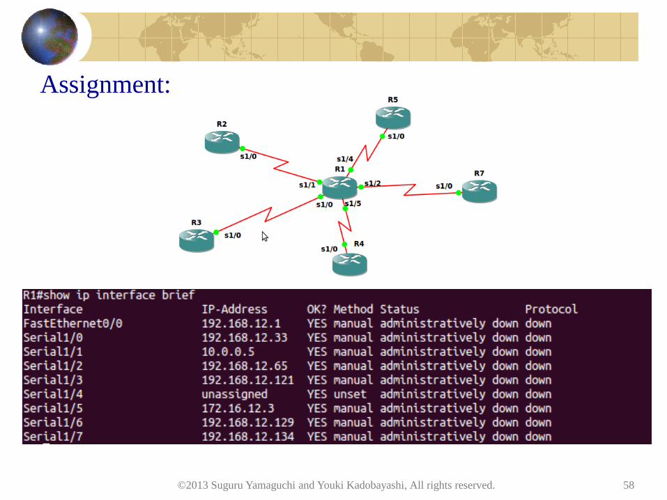
Assignment:
©2013 Suguru Yamaguchi and Youki Kadobayashi, All rights reserved. 58
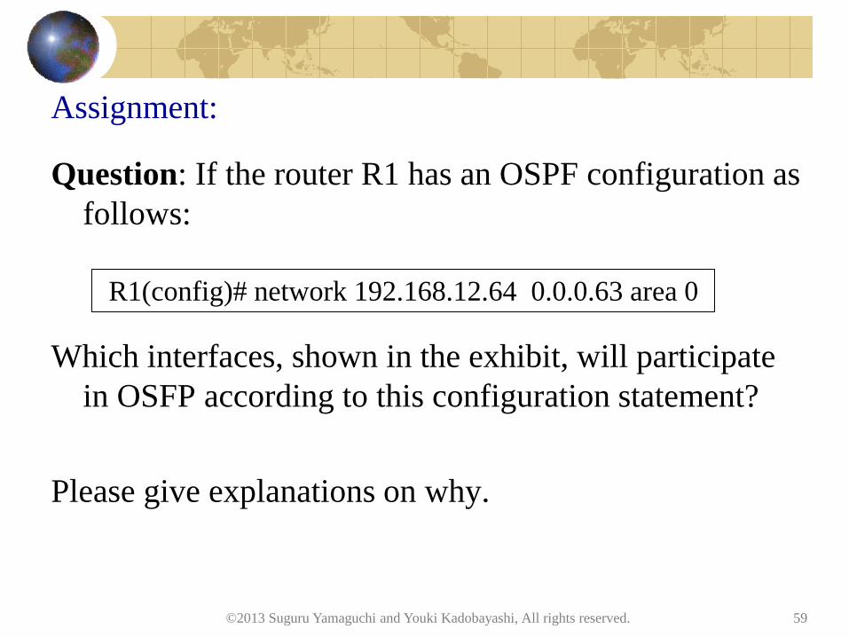
Assignment:
Question: If the router R1 has an OSPF configuration as
follows:
Which interfaces, shown in the exhibit, will participate
in OSFP according to this configuration statement?
Please give explanations on why.
©2013 Suguru Yamaguchi and Youki Kadobayashi, All rights reserved. 59
R1(config)# network 192.168.12.64 0.0.0.63 area 0
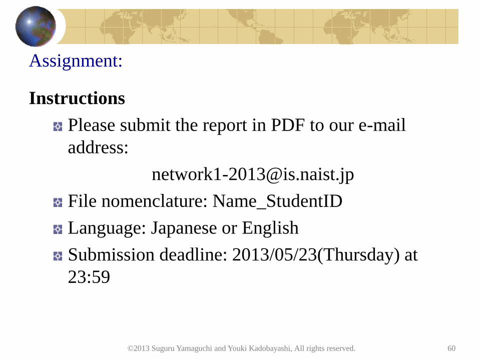
Assignment:
Instructions
Please submit the report in PDF to our e-mail
address:
File nomenclature: Name_StudentID
Language: Japanese or English
Submission deadline: 2013/05/23(Thursday) at
23:59
©2013 Suguru Yamaguchi and Youki Kadobayashi, All rights reserved. 60
Top Related