


Languages
Pages
Legal


Informatics for industrial applications
Lecture 4 - Peripherals: Analog to Digital Converter
Martino [email protected]
October 19, 2011

Introduction STM32 Analog do Digital Converter ADC registers
Outline
1 IntroductionIntroduction to Analog to Digital ConvertersAnalog to Digital Converter typesAnalog to Digital Converter characteristics
2 STM32 Analog do Digital ConverterIntroductionFeaturesADC and DMA
3 ADC registersOverview
Introduction STM32 Analog do Digital Converter ADC registers
Introduction to Analog to Digital Converters (1/2)
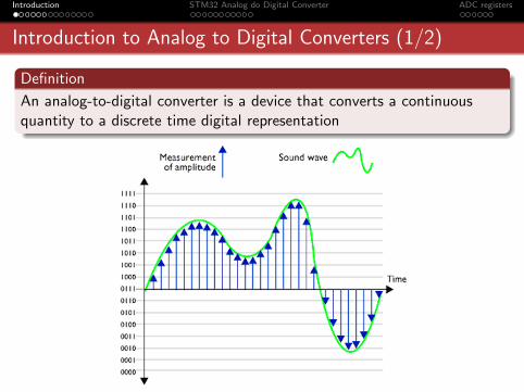
Definition
An analog-to-digital converter is a device that converts a continuousquantity to a discrete time digital representation

Introduction STM32 Analog do Digital Converter ADC registers
Introduction to Analog to Digital Converters (2/2)
Introduction STM32 Analog do Digital Converter ADC registers
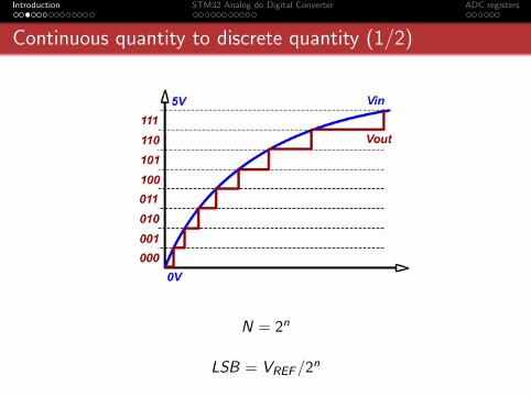
Continuous quantity to discrete quantity (1/2)
N = 2n
LSB = VREF/2n

Introduction STM32 Analog do Digital Converter ADC registers
Continuous quantity to discrete quantity (2/2)

Introduction STM32 Analog do Digital Converter ADC registers
Continuous time to discrete time (1/2)
Introduction STM32 Analog do Digital Converter ADC registers
Continuous time to discrete time (2/2)
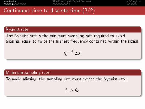
Nyquist rate
The Nyquist rate is the minimum sampling rate required to avoidaliasing, equal to twice the highest frequency contained within the signal.
fNdef= 2B
Minimum sampling rate
To avoid aliasing, the sampling rate must exceed the Nyquist rate.
fS > fN

Introduction STM32 Analog do Digital Converter ADC registers
Analog to Digital Converter diagram
Introduction STM32 Analog do Digital Converter ADC registers
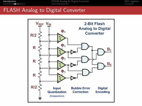
FLASH Analog to Digital Converter

Introduction STM32 Analog do Digital Converter ADC registers
SAR Analog to Digital Converter

Introduction STM32 Analog do Digital Converter ADC registers
Sigma-delta Analog to Digital Converter

Introduction STM32 Analog do Digital Converter ADC registers
Analog to Digital Converter characteristics
Resolution
Max sampling rate
Signal to Noise Ratio (SNR)
Input voltage offset
Gain stability
Linearity

Introduction STM32 Analog do Digital Converter ADC registers
Gain error
Introduction STM32 Analog do Digital Converter ADC registers
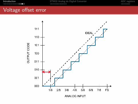
Voltage offset error

Introduction STM32 Analog do Digital Converter ADC registers
Non-linearity errors

Introduction STM32 Analog do Digital Converter ADC registers
Outline
1 IntroductionIntroduction to Analog to Digital ConvertersAnalog to Digital Converter typesAnalog to Digital Converter characteristics
2 STM32 Analog do Digital ConverterIntroductionFeaturesADC and DMA
3 ADC registersOverview

Introduction STM32 Analog do Digital Converter ADC registers
STM32 Analog do Digital Converter
Successive approximation analog-to-digital converter
12-bit resolution
Interrupt generation at End of Conversion, End of Injectedconversion and Analog watchdog event
Single and continuous conversion modes
Scan mode for automatic conversion of channel 0 to channel n
Self-calibration
External trigger option for both regular and injected conversion
Total conversion time: 14 to 252 TCK (tS for sampling + 12.5 forsuccessive approximation)

Introduction STM32 Analog do Digital Converter ADC registers
STM32 Analog do Digital Converter accuracy

Introduction STM32 Analog do Digital Converter ADC registers
Analog power supply

Introduction STM32 Analog do Digital Converter ADC registers
STM32 clock tree

Introduction STM32 Analog do Digital Converter ADC registers
STM32 Analog do Digital Converter diagram
Introduction STM32 Analog do Digital Converter ADC registers
Channel selection
16 multiplexed channels
It is possible to organize the conversions in groups
A group consists of a sequence of conversions which can be done onany channel and in any order
Regular group:
up to 16 conversionsthe conversion sequence must be selected in the ADC SQRx registers
Injected group:
up to 4 conversionsThis mode is intended for use when conversion is triggered by anexternal event or by softwareThe injected group has priority over the regular channel groupIt interrupts the conversion of the current channel in the regularchannel group

Introduction STM32 Analog do Digital Converter ADC registers
Single and continuous conversion mode
In Single conversion mode the ADC does one conversionIn Continuous mode (CONT = 1) another conversion starts as soonas it finishes oneThe conversion is started either by setting the ADON bit or byexternal triggerIf the EOCIE is set, an interrupt is generated at the end of eachconversion

Introduction STM32 Analog do Digital Converter ADC registers
Scan conversion mode
Scans a group of analog channels
A single conversion is performed for each channel of the group
After each end of conversion the next channel of the group isconverted automatically
If CONT = 1, on last channel conversion, the ADC starts againfrom the first group channel
If the DMA bit is set, the direct memory access controller is used totransfer the converted data to SRAM after each EOC

Introduction STM32 Analog do Digital Converter ADC registers
Analog watchdog
The AWD analog watchdog status bit is set if the analog voltageconverted by the ADC is below a low threshold or above a highthreshold
These thresholds are programmed in the 12 least significant bits ofthe ADC HTR and ADC LTR 16-bit registers
An interrupt can be enabled by using the AWDIE bit in theADC CR1 register

Introduction STM32 Analog do Digital Converter ADC registers
Direct Memory Access

Introduction STM32 Analog do Digital Converter ADC registers
ADC and DMA
Converted regular channels value are stored in a unique data register
It is necessary to use DMA for conversion of more than one regularchannel
The end of conversion of a regular channel generates a DMA request
Converted data is transferred from the ADC DR register to thedestination location selected by the user

Introduction STM32 Analog do Digital Converter ADC registers
Outline
1 IntroductionIntroduction to Analog to Digital ConvertersAnalog to Digital Converter typesAnalog to Digital Converter characteristics
2 STM32 Analog do Digital ConverterIntroductionFeaturesADC and DMA
3 ADC registersOverview
Introduction STM32 Analog do Digital Converter ADC registers
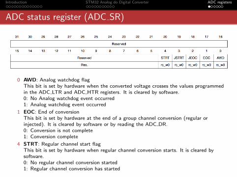
ADC status register (ADC SR)
0 AWD: Analog watchdog flagThis bit is set by hardware when the converted voltage crosses the values programmedin the ADC LTR and ADC HTR registers. It is cleared by software.0: No Analog watchdog event occurred1: Analog watchdog event occurred
1 EOC: End of conversionThis bit is set by hardware at the end of a group channel conversion (regular orinjected). It is cleared by software or by reading the ADC DR.0: Conversion is not complete1: Conversion complete
4 STRT: Regular channel start flagThis bit is set by hardware when regular channel conversion starts. It is cleared bysoftware.0: No regular channel conversion started1: Regular channel conversion has started

Introduction STM32 Analog do Digital Converter ADC registers
ADC control register 1 (ADC CR1)
4:0 AWDCH[4:0]: Analog watchdog channel select bitsThese bits are set and cleared by software. They select the input channel to be guardedby the Analog watchdog.00000: ADC analog input Channel0...10001: ADC analog input Channel17
5 EOCIE: Interrupt enable for EOCThis bit is set and cleared by software to enable/disable the End of Conversion interrupt.0: EOC interrupt disabled1: EOC interrupt enabled. An interrupt is generated when the EOC bit is set.
8 SCAN: Scan modeThis bit is set and cleared by software to enable/disable Scan mode. In Scan mode, theinputs selected through the ADC SQRx or ADC JSQRx registers are converted.0: Scan mode disabled1: Scan mode enabled

Introduction STM32 Analog do Digital Converter ADC registers
ADC control register 2 (ADC CR2)
0 ADON: A/D converter ON/OFFIf this bit holds a value of zero and a 1 is written to it then it wakes up the ADC fromPower Down state.Conversion starts when this bit holds a value of 1 and a 1 is written to it.0: Disable ADC conversion and go to power down mode.1: Enable ADC and to start conversion
1 CONT: Continuous conversion0: Single conversion mode1: Continuous conversion mode
8 DMA: Direct memory access mode0: DMA mode disabled1: DMA mode enabled
11 ALIGN: Data alignment0: Right Alignment1: Left Alignment

Introduction STM32 Analog do Digital Converter ADC registers
ADC sample time register 1 (ADC SMPR1)
4:0 SMPx[2:0]: Channel x Sample time selectionThese bits are written by software to select the sample time individually for eachchannel.000: 1.5 cycles001: 7.5 cycles010: 13.5 cycles011: 28.5 cycles100: 41.5 cycles101: 55.5 cycles110: 71.5 cycles111: 239.5 cycles

Introduction STM32 Analog do Digital Converter ADC registers
ADC regular sequence register 1 (ADC SQR1)
19:15 SQ16[4:0]: 16th conversion in regular sequenceThese bits are written by software with the channel number (0..17) assigned as the 16thin the conversion sequence.
23:20 L[3:0]: Regular channel sequence lengthThese bits are written by software to define the total number of conversions in theregular channel conversion sequence.0000: 1 conversion0001: 2 conversions...1111: 16 conversions
Introduction STM32 Analog do Digital Converter ADC registers
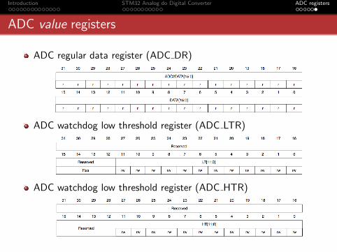
ADC value registers
ADC regular data register (ADC DR)
ADC watchdog low threshold register (ADC LTR)
ADC watchdog low threshold register (ADC HTR)

References
http://en.wikipedia.org/wiki/Analog to digital converter
http://en.wikipedia.org/wiki/Sample and hold
http://en.wikipedia.org/wiki/Quantization error
http://en.wikipedia.org/wiki/Nyquist rate
http://en.wikipedia.org/wiki/Nyquist frequency
http://en.wikipedia.org/wiki/Flash ADC
http://en.wikipedia.org/wiki/Successive Approximation ADC
http://en.wikipedia.org/wiki/Sigma-delta modulation
STM32F10xxx Reference Manual (RM0008 - Doc ID 14611)
Application note: STM32 ADC modes and their applications (AN3116 - Doc ID
16840)
Top Related