


Languages
Pages
Legal

Infiltration Gallery Guidelines Design, Construction, Operation &
Maintenance
Prepared for Marlborough District Council
Report No 14003/2
April 2014
w w w . a qua l i nc . c o m
CHRISTCHURCH PO Box 20-462, Bishopdale 8543, Christchurch ♦ Phone: (03) 964 6521 ♦ Fax: (03) 964 6520 HAMILTON PO Box 14-041, Enderley 3252, Hamilton ♦ Phone: (07) 858 4851 ♦ Fax: (07) 858 4847
ASHBURTON PO Box 557, Ashburton 7740 ♦ Phone: (03) 307 6680 ♦ Fax: (03) 307 1581
Disclaimer: This report has been prepared solely for the benefit of Marlborough District Council. No liability is accepted by Aqualinc Research Ltd or any employee or sub-consultant of this Company with respect to its use by any other person. This disclaimer shall apply notwithstanding that the report may be made available to other persons for an application for permission or approval or to fulfil a legal requirement.
Quality Control
Client: Marlborough District Council
Report reference: Title: Infiltration Gallery Guidelines - Design, Construction, Operation & Maintenance
No: 14003/2
Prepared by: Fraser Scales
Reviewed by: Ian McIndoe Approved for issue by: IM
Date issued: April 2014 Project No: C14003
Document History
Version: 1 Status: 1st Draft Author: Fraser Reviewer: IM
Version: 2 Status: 2st Draft – Client Issue Author: Fraser Reviewer: IM
Version: 3 Status: Final Author: Fraser Reviewer: IM
Date: 15-4-14 Doc ID: Infiltration_Gallery_Guidelines (5) Typist: Fraser Approver: IM/VW
© All rights reserved. This publication may not be reproduced or copied in any form, without the permission of the Client. Such permission is to be given only in accordance with the terms of the Client’s contract with Aqualinc Research Ltd. This copyright extends to all forms of copying and any storage of material in any kind of information retrieval system.
Infiltration Gallery Guidelines Design, Construction, Operation & Maintenance © Aqualinc Research Ltd Prepared for Marlborough District Council (Report No 14003/2, April 2014) Page i
TABLE OF CONTENTS
Page
Summary ................................................................................................................................... 1
Guide to use .............................................................................................................................. 1
1 Introduction .................................................................................................................... 3 1.1 Infiltration Galleries ................................................................................................ 3 1.2 The Role of Infiltration Galleries ............................................................................ 3 1.3 Principals of Infiltration Galleries........................................................................... 3 1.4 Project Background ................................................................................................. 4 1.5 Purpose and Scope of Guide ................................................................................... 5
2 River Intakes ................................................................................................................... 6 2.1 Alternative Intake Methods ..................................................................................... 6 2.2 Typical uses for Infiltration Galleries ..................................................................... 6 2.3 Intake Method Comparison ..................................................................................... 7 2.4 Advantages and Challenges of Infiltration Galleries .............................................. 7
3 Guide to the Design Procedure ...................................................................................... 8 3.1 Introduction ............................................................................................................. 8 3.2 The Design Process ................................................................................................. 8 3.3 Feasibility of using an Infiltration Gallery ............................................................ 10 3.4 Outline Approvals ................................................................................................. 12 3.5 Site Investigations ................................................................................................. 13
3.5.1 Hydraulic & Sediment load Testing .......................................................... 14 3.5.2 Stratigraphy and Ground Profile ............................................................... 14 3.5.3 Hydrogeological Testing ........................................................................... 14 3.5.4 Groundwater levels ................................................................................... 15 3.5.5 Water Quality Testing ............................................................................... 15
3.6 Select Gallery Type ............................................................................................... 16 3.7 Design of Infiltration Gallery Systems ................................................................. 17
3.7.1 Analyse Groundwater System ................................................................... 18 3.7.2 Estimate Safe Yield ................................................................................... 18 3.7.3 Geotechnical Design ................................................................................. 20
3.7.4 Hydraulic Design ...................................................................................... 22 3.7.5 Pollution Control ....................................................................................... 24 3.7.6 Operation and Maintenance ...................................................................... 26 3.7.7 Appraisal of Costs ..................................................................................... 28
4 Conclusions ................................................................................................................... 30
Infiltration Gallery Guidelines Design, Construction, Operation & Maintenance © Aqualinc Research Ltd Prepared for Marlborough District Council (Report No 14003/2, April 2014) Page ii
List of Tables:
Table 1: Permeability estimation methods. .............................................................................. 14
Table 2: Water quality testing methods. .................................................................................. 15
Table 3: Conceptual model parameters.................................................................................... 18
Table 4: Routine and non-routine gallery maintenance. .......................................................... 26
List of Figures:
Figure 1: A typical (i) infiltration gallery (ii) embankment infiltration well ............................ 3
Figure 2: Generic intake options. .............................................................................................. 6
Figure 3: Overall design process for infiltration galleries. ....................................................... 9
Figure 4: Feasibility questions. ................................................................................................ 10
Figure 5: Outline approvals process. ...................................................................................... 12
Figure 6: The process of site investigation ............................................................................. 13
Figure 7: Selection of system type .......................................................................................... 16
Figure 8: Infiltration gallery design process ........................................................................... 17
Figure 9: Geotechnical design process. .................................................................................. 20
Figure 10: Hydraulic design process........................................................................................ 22
Figure 11: Pollution control. .................................................................................................... 24
Figure 12: Operation and maintenance process ....................................................................... 27
Figure 13: Appraisal of costs process. ..................................................................................... 28
Infiltration Gallery Guidelines Design, Construction, Operation & Maintenance © Aqualinc Research Ltd Prepared for Marlborough District Council (Report No 14003/2, April 2014) Page 1
SUMMARY
This report provides a guide to good practice for those involved in the planning, appraisal, approval, funding, design, construction, operation and maintenance of intakes that use infiltration as a method to capture, control and distribute river water. The guide discusses the advantages and limitations of using infiltration galleries and provides the information to assist practitioners who decide whether, in given circumstances, infiltration galleries are appropriate. Good design enhances performance, and minimises the need for ongoing maintenance. If installed and operated efficiently, buried galleries can have less impact on the environment than any other water supply intake. However, an increase in the frequency of maintenance works because of poor design will significantly negate these benefits, and in some instances, cause more river bed disturbance than a surface intake would. Water quality is also an important aspect of the design of infiltration galleries. However, this guide does not provide guidance on these issues or on any of the legal issues surrounding the use of infiltration galleries in New Zealand. This report is not a technical design guide but rather an overview of the design factors and processes required to realise the greatest benefit to the environment, a reduction in bed disturbances, reduced ecosystem disturbance in the area of construction, and improved water quality.
This report does not contain all the detailed information that has been obtained during the course of the project and which forms the background to its recommendations. Reference may be made to the following report which has been published separately in support of the guidelines: Infiltration Gallery Design in the Marlborough Region
GUIDE TO USE
This manual is designed for those involved in the planning, appraisal, approval, funding, design, construction operation and maintenance of infiltration galleries. The guide is structured as follows: Section 1 introduces the topic of infiltration galleries and presents the background to the present study. Section 2 discusses the role of infiltration galleries in the context of river water abstraction and outlines the main types of infiltration gallery systems. The advantages and disadvantages of using infiltration galleries are also detailed. Section 3 provides a framework for designing infiltration galleries.
Section 4 summarises the main conclusions from the project.

Infiltration Gallery Guidelines Design, Construction, Operation & Maintenance © Aqualinc Research Ltd Prepared for Marlborough District Council (Report No 14003/2, April 2014) Page 2
NOTATION
A Area a Length of system B Partial penetration factor C Calibration factor D Thickness of confined aquifer Dx Sieve aperture d Depth to water table F Factor of safety H Initial groundwater head h Total hydraulic head (H – h) Drawdown i Hydraulic gradient k Coefficient of permeability kh Horizontal conductance kv Vertical conductance L0 Distance of influence lw Wetted length of screen P Depth of penetration into aquifer Q Discharge S Storage coefficient T Transmissivity x Linear distance λ Partial penetration factor
Infiltration Gallery Guidelines Design, Construction, Operation & Maintenance © Aqualinc Research Ltd Prepared for Marlborough District Council (Report No 14003/2, April 2014) Page 3
1 INTRODUCTION
1.1 Infiltration Galleries
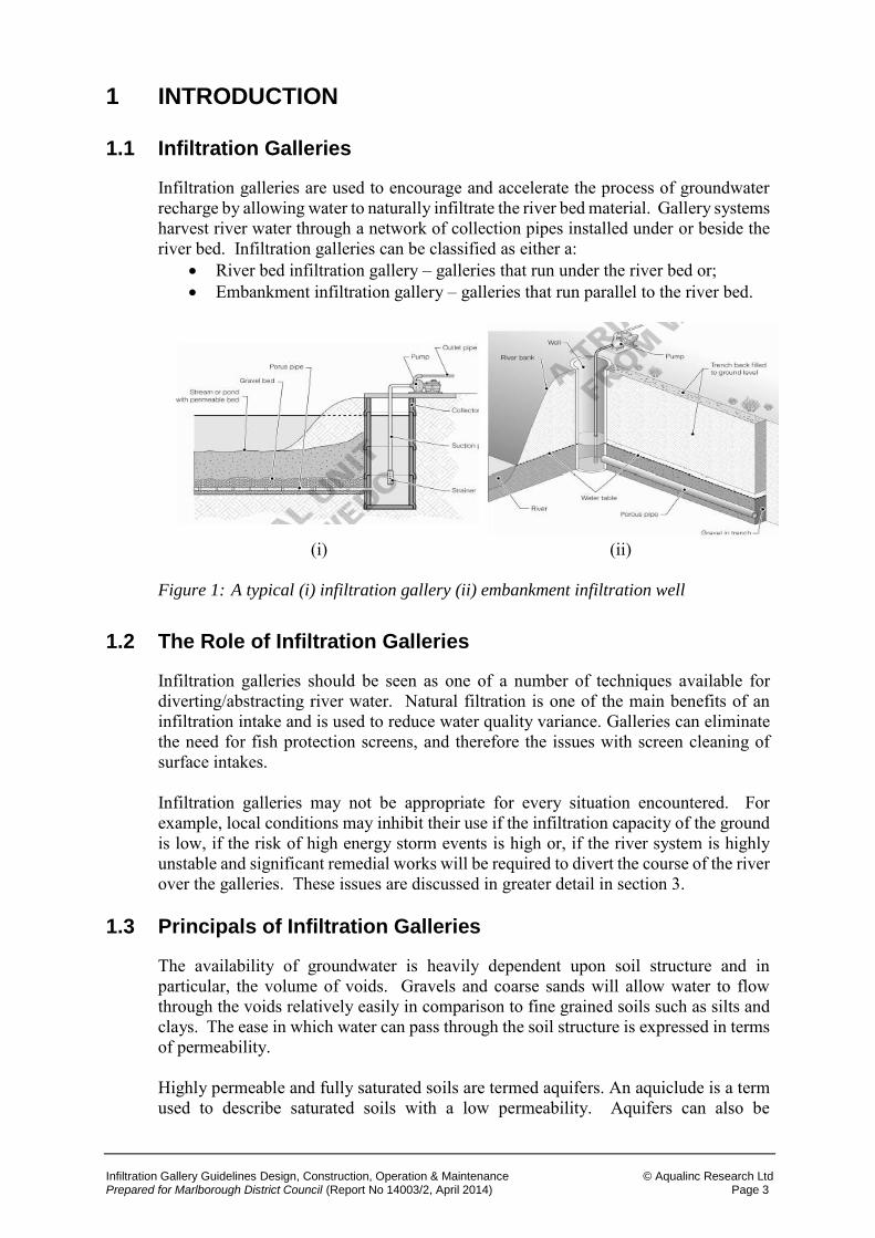
Infiltration galleries are used to encourage and accelerate the process of groundwater recharge by allowing water to naturally infiltrate the river bed material. Gallery systems harvest river water through a network of collection pipes installed under or beside the river bed. Infiltration galleries can be classified as either a:
River bed infiltration gallery – galleries that run under the river bed or; Embankment infiltration gallery – galleries that run parallel to the river bed.
(i)
(ii)
Figure 1: A typical (i) infiltration gallery (ii) embankment infiltration well
1.2 The Role of Infiltration Galleries
Infiltration galleries should be seen as one of a number of techniques available for diverting/abstracting river water. Natural filtration is one of the main benefits of an infiltration intake and is used to reduce water quality variance. Galleries can eliminate the need for fish protection screens, and therefore the issues with screen cleaning of surface intakes. Infiltration galleries may not be appropriate for every situation encountered. For example, local conditions may inhibit their use if the infiltration capacity of the ground is low, if the risk of high energy storm events is high or, if the river system is highly unstable and significant remedial works will be required to divert the course of the river over the galleries. These issues are discussed in greater detail in section 3.
1.3 Principals of Infiltration Galleries
The availability of groundwater is heavily dependent upon soil structure and in particular, the volume of voids. Gravels and coarse sands will allow water to flow through the voids relatively easily in comparison to fine grained soils such as silts and clays. The ease in which water can pass through the soil structure is expressed in terms of permeability. Highly permeable and fully saturated soils are termed aquifers. An aquiclude is a term used to describe saturated soils with a low permeability. Aquifers can also be
Infiltration Gallery Guidelines Design, Construction, Operation & Maintenance © Aqualinc Research Ltd Prepared for Marlborough District Council (Report No 14003/2, April 2014) Page 4
unconfined or confined. An unconfined aquifer is exposed to the atmosphere whilst a confined aquifer is overlain with a relatively impermeable stratum. Infiltration gallery systems are a form of river intake structure used to collect and distribute river water from alluvial/shallow aquifers. As the system is usually housed below the water table, it can also be considered a direct recharge system. The governing principals, used in the design gallery systems, are similar to those used for the design of drainage systems. In essence, the proficient designer will seek to effectively and efficiently facilitate the movement of water through the soil structure, without compromising the surrounding environment. For an infiltration gallery system to be effective, the surface water body must be close enough to the structure and have a surface area large enough to allow processes such as infiltration and seepage to occur. The size of the required recharge area (A) is dictated by the hydraulic properties of the soil, namely its permeability (k), and the required discharge (Q), as stipulated by Darcy’s law.
𝑸 = 𝑨𝒌𝒊 1.4 Project Background
Soakaways have traditionally provided drainage for housing and were the most common form of infiltration drainage system until the recent uptake of sustainable urban drainage systems (SUDS). Over recent years, the drainage sector has experienced a shift away from the traditional ‘hard’ approach of conveying water away as quickly as possible through a network of pipes, towards more sustainable ‘soft’ solutions that seek to simulate naturally occurring processes. This has led to the development of a broad body of knowledge in the field of groundwater design. There is an apparent gap between the abstraction techniques being exercised and the industry’s recognised body of knowledge. Whilst the use of infiltration systems has been widely endorsed by industry practitioners in the field of drainage, there is a distinct lack of comprehensive technical design guidance and industry understanding on the use of infiltration systems for the purpose of abstracting and diverting surface water. Guidelines for the construction of infiltration systems are available in the form of AS-NZS 3500-3: Plumbing and Drainage: Storm Water Drainage. However, the guide places an emphasis on drainage and is technically limited. Buried gallery intakes are becoming more commonly used by irrigators to abstract water for irrigation, particularly in regions where fine sediment stays in suspension for long periods, even during times of low flows. Gallery intakes may be in-stream, in riparian gravels, or on a diversion from the river. Water may also be abstracted from sub-surface flows in seemingly dry transient streams. From a user’s perspective, gallery intakes provide natural filtration, which is widely considered to be more effective than mechanical filtration systems. Associated with the concept of risk is reliability, which is usually expressed as the probability that a system will perform to the required specification for a defined period of time. Risk is also dependent upon the consequences of failure and is defined as:
𝑹𝒊𝒔𝒌 = 𝑷𝒓𝒐𝒃𝒂𝒃𝒊𝒍𝒊𝒕𝒚 𝒐𝒇 𝑭𝒂𝒊𝒍𝒖𝒓𝒆 × 𝑪𝒐𝒏𝒔𝒆𝒒𝒖𝒆𝒏𝒄𝒆𝒔 𝒐𝒇 𝑭𝒂𝒊𝒍𝒖𝒓𝒆
Infiltration Gallery Guidelines Design, Construction, Operation & Maintenance © Aqualinc Research Ltd Prepared for Marlborough District Council (Report No 14003/2, April 2014) Page 5
The consequences of failure are always dependent upon the user value for water, the timing of failure and the effects of failure on the environment. In contrast, the probability of failure is a characteristic of the system and can be controlled through good design. Poorly designed systems have an increased probability of failure and are subsequently associated with higher degrees of risk. The operational lives of galleries have been highly variable, with frequent reductions in yield and in some cases sudden and complete gallery failure occurring. In many instances, failure occurs during periods of peak demand, which can have devastating consequences on the user’s activities and on the environment. Any form of construction or maintenance activities in or near surface water has the potential to cause serious pollution or impact the quality and quantity of water. Many galleries have had to undergo major maintenance or be completely reinstalled to reinstate the water supply. If the value of water is high (i.e. irrigation), the user may have no choice but to immediately conduct remedial works, regardless of the environmental implications.
1.5 Purpose and Scope of Guide
This report provides a guide to good practice for those involved in the planning, appraisal, approval, funding, design, construction operation and maintenance who wish to use infiltration as a method to capture, control and distribute river water. The guide discusses the advantages and disadvantages of using infiltration galleries and provides the information to assist practitioners who decide whether, in given circumstances, infiltration galleries are appropriate and, if so, how to proceed to design, construct and maintain them. Water quality is an important aspect of the design of infiltration galleries. However, this guide does not provide guidance on these issues or on any of the legal issues surrounding the use of infiltration galleries in New Zealand. The manual provides information which will enable its readers to: (a) Assess the feasibility and determine the type of infiltration gallery (b) Conduct field tests and relate the data to design (c) Specify and design the infiltration gallery (d) Incorporate suitable pollution control measures to the design.
Infiltration Gallery Guidelines Design, Construction, Operation & Maintenance © Aqualinc Research Ltd Prepared for Marlborough District Council (Report No 14003/2, April 2014) Page 6
2 RIVER INTAKES
River intakes can have the following detrimental effects on river morphology:
Increase rates of sediment deposition and reduce the volume of sediment conveyed to downstream reaches.
Increase rates of sediment deposition can lead to the need for sediment removal. Entrapment of fish. Loss or damage to riparian ecosystem.
The objective of any river intake structure should be to abstract the required volume of water at a sustainable rate whilst minimising the effects of abstraction, construction, use and maintenance on the local environment.
2.1 Alternative Intake Methods
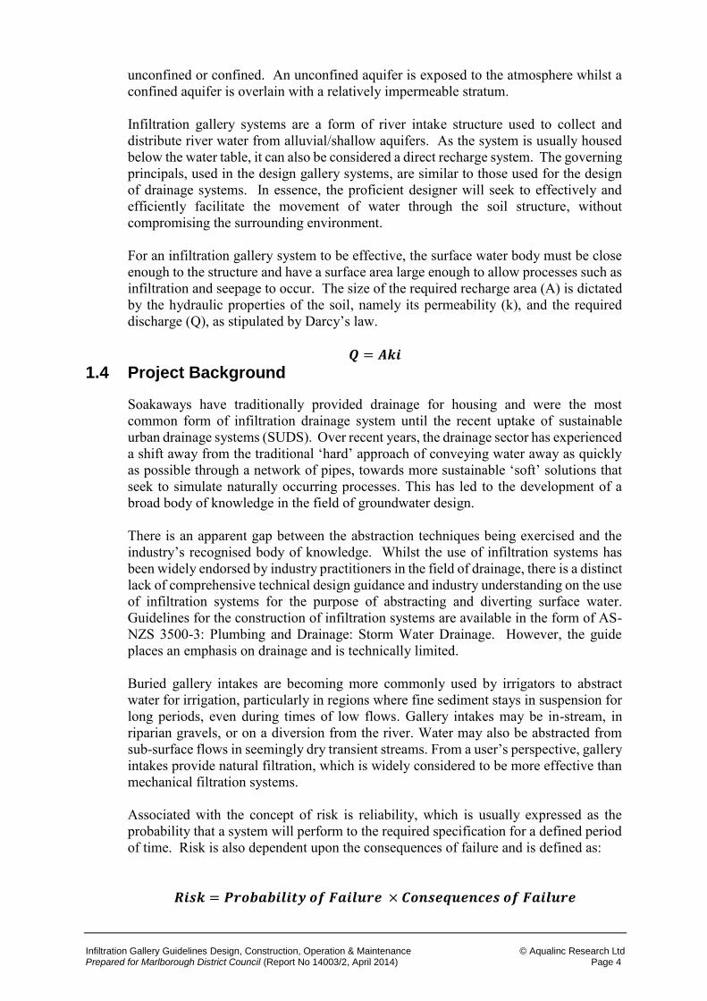
Figure 2: Generic intake options.
Figure 1 illustrates the five generic intake options available. As will be seen, infiltration galleries fall under the submerged classification, whilst embankment galleries fall under the embankment with no river bed structure classification. Figure 1 makes it clear that infiltration galleries are one of a number of techniques available. The use of an infiltration gallery system is often determined by the need to utilise natural filtration in order to improve water quality.
2.2 Typical uses for Infiltration Galleries
Galleries are common in environments where the depth of embedment is significantly limited by the aquifer thickness and hence, the required yield cannot be obtained from a vertical well. Buried gallery intakes are becoming more commonly used by irrigators to abstract water for irrigation from rivers where fine sediment stays in suspension for long periods, even during times of low flows. They can also be used as part of a small scale potable water supply schemes or to provide filtered water for industrial use. An underlying theme for all of the discussed uses is water quality and in particular, the removal of fines. An infiltration gallery should, therefore, be seen as an alternative to
INTAKE
EMBANKMENT NO RIVER BED
STRUCTURE
EMBANKMENT WITH RIVER BED
STRUCTURE
EMBANKMENT WITH WEIR
BED INTAKE SUBMERGED
Infiltration Gallery Guidelines Design, Construction, Operation & Maintenance © Aqualinc Research Ltd Prepared for Marlborough District Council (Report No 14003/2, April 2014) Page 7
providing mechanical filtration systems. Providing the design takes full account of the physical site conditions and the system is adequately maintained once installed, infiltration galleries can be an attractive and cost-effective intake solution.
2.3 Intake Method Comparison
A fair and equitable cost comparison between an infiltration gallery system and the alternative intake solutions presented in Figure 1 will take into account the following points: (a) Infiltration gallery option(s)
The complete cost of installation to the downstream end of the pump headworks.
Any future enhancements that may need to be made to maintain the required yield.
Water quality benefits. Frequency and cost of maintenance works including environmental effects. Annual operational costs which must account for components of the system
deemed expendable. (b) Alternative option(s)
The complete cost of installation to the downstream end of the pump headworks.
Cost of filtration. Frequency and cost of maintenance works. Annual operational costs which must account for components of the system
deemed expendable. These considerations are discussed in greater depth in section 3.7.7. The adoption of the infiltration gallery system that provides the best quality of water can be the most attractive option but not always the most cost effective.
2.4 Advantages and Challenges of Infiltration Galleries
The main advantages of infiltration gallery systems are as follows:
Natural infiltration can significantly improve water quality. Whole-life costs may be less than alternative intake types. Correctly designed and well maintained systems can have less of a detrimental
impact on the local environment than more conventional intake systems. The main challenges with infiltration gallery systems are as follows:
Gallery performance is dependent on the properties of the soil in which they are constructed.
Ground investigations are required to determine the design parameters. Whilst the hydraulic conductivity of the ground may be good, transmissivity
may be poor if the aquifers saturated depth is low. The introduction of water into the soil may induce geotechnical problems.

Infiltration Gallery Guidelines Design, Construction, Operation & Maintenance © Aqualinc Research Ltd Prepared for Marlborough District Council (Report No 14003/2, April 2014) Page 8
Poorly designed systems can experience a significant reduction in yield if the filter pack becomes blinded through ingress of silt.
Gallery systems require regular maintenance to sustain design performance. Specialist trenching machines may be required to reduce ground pressures
during construction. The presence of clay can present many technical difficulties and hinder gallery
performance. Mobilisation and demobilisation costs can be high.
3 GUIDE TO THE DESIGN PROCEDURE
3.1 Introduction
The overall procedure for planning, appraising and designing an infiltration gallery system is described in this section.
3.2 The Design Process
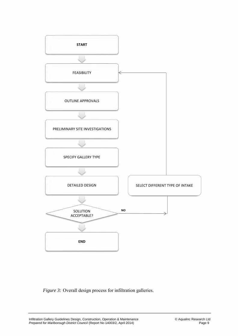
The overall design process illustrated in Figure 3 aims to reduce the risk of gallery failure and avoid the environmental and financial consequences of failure by promoting good design practice, installation, operation and maintenance. The process is broken down into more detailed tasks in the following sections of this report.
Infiltration Gallery Guidelines Design, Construction, Operation & Maintenance © Aqualinc Research Ltd Prepared for Marlborough District Council (Report No 14003/2, April 2014) Page 9
Figure 3: Overall design process for infiltration galleries.
START
FEASIBILITY
OUTLINE APPROVALS
PRELIMINARY SITE INVESTIGATIONS
SPECIFY GALLERY TYPE
DETAILED DESIGN
SOLUTION ACCEPTABLE?
END
SELECT DIFFERENT TYPE OF INTAKE
NO
Infiltration Gallery Guidelines Design, Construction, Operation & Maintenance © Aqualinc Research Ltd Prepared for Marlborough District Council (Report No 14003/2, April 2014) Page 10
3.3 Feasibility of using an Infiltration Gallery
Figure 4: Feasibility questions.
START
CAN THE DAILY VOLUME BE
ABSTRACTED?
IS THERE A HIGH FLOOD RISK?
ARE THERE VIABLE ALTERNATIVE,
METHODS AVAILABLE?
IS THE ENVIRONMENTAL IMPACT OF THE SYSTEM HIGH?
WILL WATER QUALITY
IMPROVE?
ARE THERE GEOTECHNICAL CONSTRAINTS?
GO TO OUTLINE APPROVALS
USE ALTERNATIVE FORM OF INTAKE
USE ALTERNATIVE FORM OF INTAKE
USE ALTERNATIVE FORM OF INTAKE
USE ALTERNATIVE FORM OF INTAKE
USE ALTERNATIVE FORM OF INTAKE
USE ALTERNATIVE FORM OF INTAKE
NO
YES
YES
YES
NO
YES
Infiltration Gallery Guidelines Design, Construction, Operation & Maintenance © Aqualinc Research Ltd Prepared for Marlborough District Council (Report No 14003/2, April 2014) Page 11
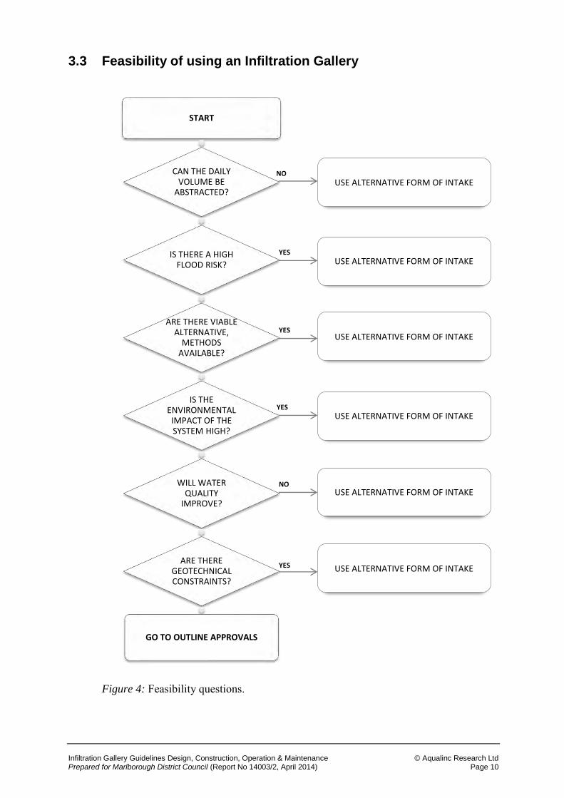
Prior to the initiation of any detailed design work, the feasibility of installing an infiltration gallery system must be considered. This is to ensure that there is no fundamental reason why an infiltration gallery will not be appropriate. For smaller schemes, a small qualitative assessment may only be required. However, for larger projects, some form of preliminary design work and costing should be developed and analysed. The feasibility analysis will vary depending on the particular abstraction problem under consideration. However, in general, the following points ought to be given due consideration and should address the more frequently encountered difficulties. The decision process is presented in Figure 4. What is the daily volume of water to be abstracted? Can infiltration methods meet the volume of water required? Are there viable alternative, cheaper methods available for water abstraction? Will the installation have a detrimental impact on the environment? Does the river water quality prevent the use of an infiltration gallery e.g. is the water
very turbid or polluted? Do geotechnical problems prevent the use of infiltration galleries? What would the consequences of a flood event be in the installation?
Infiltration Gallery Guidelines Design, Construction, Operation & Maintenance © Aqualinc Research Ltd Prepared for Marlborough District Council (Report No 14003/2, April 2014) Page 12
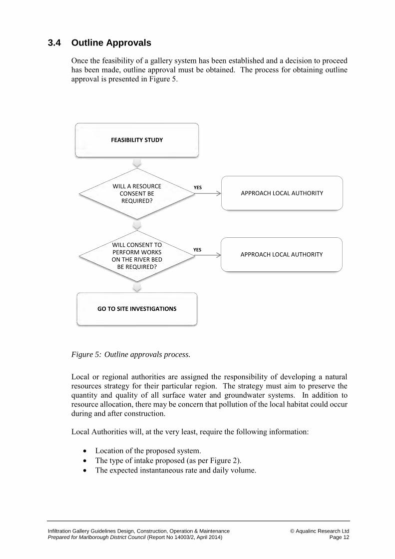
3.4 Outline Approvals
Once the feasibility of a gallery system has been established and a decision to proceed has been made, outline approval must be obtained. The process for obtaining outline approval is presented in Figure 5.
Figure 5: Outline approvals process.
Local or regional authorities are assigned the responsibility of developing a natural resources strategy for their particular region. The strategy must aim to preserve the quantity and quality of all surface water and groundwater systems. In addition to resource allocation, there may be concern that pollution of the local habitat could occur during and after construction. Local Authorities will, at the very least, require the following information:
Location of the proposed system. The type of intake proposed (as per Figure 2). The expected instantaneous rate and daily volume.
FEASIBILITY STUDY
WILL A RESOURCE CONSENT BE REQUIRED?
WILL CONSENT TO PERFORM WORKS ON THE RIVER BED
BE REQUIRED?
GO TO SITE INVESTIGATIONS
APPROACH LOCAL AUTHORITY
APPROACH LOCAL AUTHORITY
YES
YES
Infiltration Gallery Guidelines Design, Construction, Operation & Maintenance © Aqualinc Research Ltd Prepared for Marlborough District Council (Report No 14003/2, April 2014) Page 13
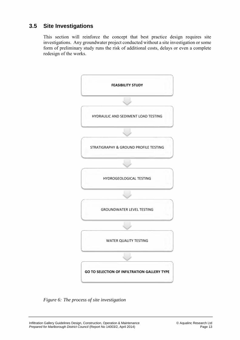
3.5 Site Investigations
This section will reinforce the concept that best practice design requires site investigations. Any groundwater project conducted without a site investigation or some form of preliminary study runs the risk of additional costs, delays or even a complete redesign of the works.
Figure 6: The process of site investigation
FEASIBILITY STUDY
HYDRAULIC AND SEDIMENT LOAD TESTING
STRATIGRAPHY & GROUND PROFILE TESTING
HYDROGEOLOGICAL TESTING
GROUNDWATER LEVEL TESTING
WATER QUALITY TESTING
GO TO SELECTION OF INFILTRATION GALLERY TYPE
Infiltration Gallery Guidelines Design, Construction, Operation & Maintenance © Aqualinc Research Ltd Prepared for Marlborough District Council (Report No 14003/2, April 2014) Page 14
The purpose of the site investigation is to identify through testing the key design parameters and to identify any potential complications that could impede the short and/or long term performance of the infiltration gallery system.
The following is a summary of site investigations applicable to the design of an infiltration gallery system.
3.5.1 Hydraulic & Sediment load Testing
An estimate of a rivers sediment load profile is required to ensure that the gallery structure does not have its performance impaired by sediment deposition or scour. Consideration should be given to seasonal flow variations, which will affect: The volume of sediment being transported; Method of transport (i.e. bedload or suspended); Localised areas of accretion/erosion; Human activities upstream of the proposed gallery intake.
3.5.2 Stratigraphy and Ground Profile
Correct identification and appreciation of the relative location of water-bearing strata and low permeability sediment is crucial. This can be achieved through the use of several boreholes and/or trial pits. A short stratigraphy report should be produced detailing the relationship between any identified and/or anticipated confining strata, unconfined aquifers, aquitards and aquicludes. The report should also state what the expected effects of abstraction are on the ground water system.
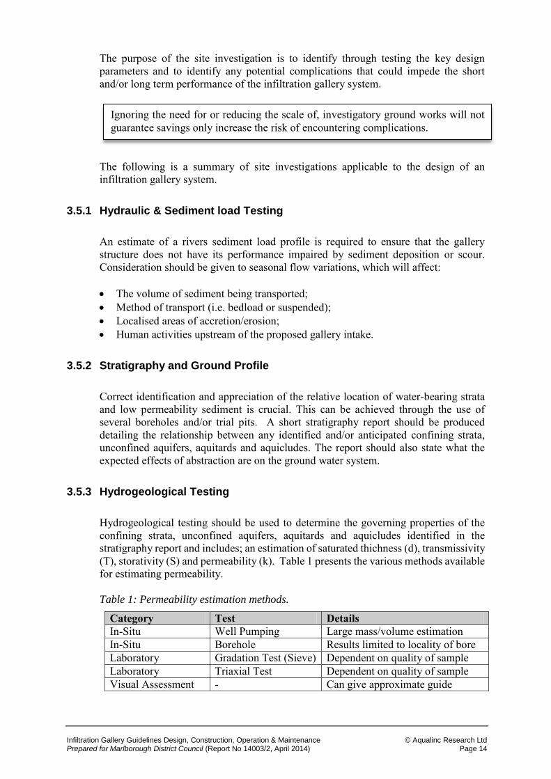
3.5.3 Hydrogeological Testing
Hydrogeological testing should be used to determine the governing properties of the confining strata, unconfined aquifers, aquitards and aquicludes identified in the stratigraphy report and includes; an estimation of saturated thichness (d), transmissivity (T), storativity (S) and permeability (k). Table 1 presents the various methods available for estimating permeability. Table 1: Permeability estimation methods.
Category Test Details In-Situ Well Pumping Large mass/volume estimation In-Situ Borehole Results limited to locality of bore Laboratory Gradation Test (Sieve) Dependent on quality of sample Laboratory Triaxial Test Dependent on quality of sample Visual Assessment - Can give approximate guide
Ignoring the need for or reducing the scale of, investigatory ground works will not guarantee savings only increase the risk of encountering complications.
Infiltration Gallery Guidelines Design, Construction, Operation & Maintenance © Aqualinc Research Ltd Prepared for Marlborough District Council (Report No 14003/2, April 2014) Page 15
The determination of matrix permeability is of significant importance and is also critical to the calculation of the systems safe yield. The following points should be considered before conducting any hydrogeological testing. 1. The ground is likely to be heterogeneous and anisotropic, which will prevent a
definitive permeability value from being obtained. A conservative approach should be adopted to account for variability in ground conditions.
2. Permeability may be anisotropic i.e. horizontal permeability (kh) is greater than the vertical (kv).
3. Permeability is not only dependent on the soils description and grading but also on
fissuring and layering, which can cover an extensive area. Laboratory testing of borehole samples should only be used if in-situ well pumping tests, which provide a better estimate of localised permeability, cannot be conducted.
3.5.4 Groundwater levels
This section is only applicable for embankment galleries where the groundwater level in relation to the proposed gallery is not known. Groundwater levels may vary considerably over time and be influenced by a variety of factors such as:
Tides or flooding. Seasonal climatic variations.
Atmospheric pressure. Existing pumping systems.
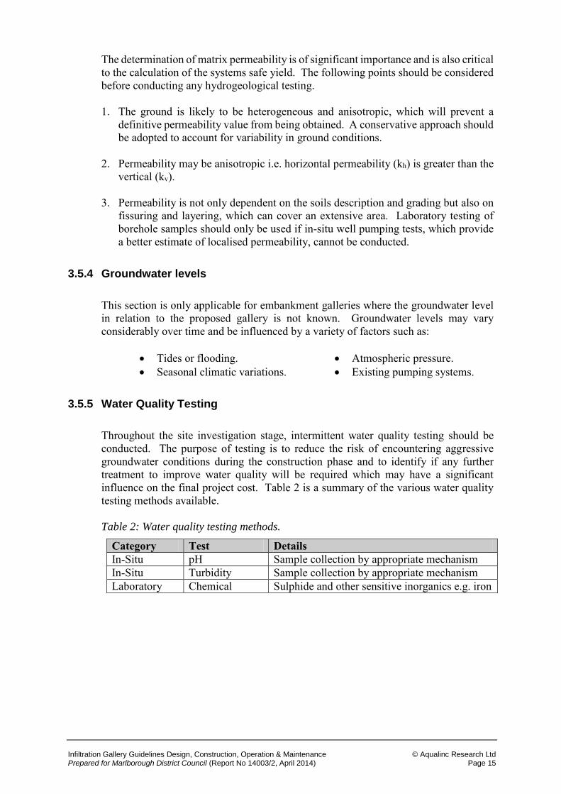
3.5.5 Water Quality Testing
Throughout the site investigation stage, intermittent water quality testing should be conducted. The purpose of testing is to reduce the risk of encountering aggressive groundwater conditions during the construction phase and to identify if any further treatment to improve water quality will be required which may have a significant influence on the final project cost. Table 2 is a summary of the various water quality testing methods available. Table 2: Water quality testing methods.
Category Test Details In-Situ pH Sample collection by appropriate mechanism In-Situ Turbidity Sample collection by appropriate mechanism Laboratory Chemical Sulphide and other sensitive inorganics e.g. iron
Infiltration Gallery Guidelines Design, Construction, Operation & Maintenance © Aqualinc Research Ltd Prepared for Marlborough District Council (Report No 14003/2, April 2014) Page 16
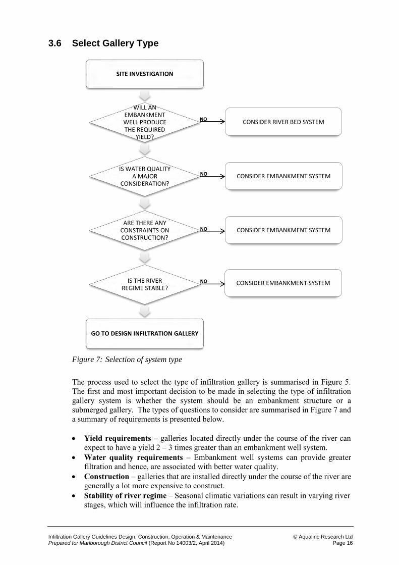
3.6 Select Gallery Type
Figure 7: Selection of system type
The process used to select the type of infiltration gallery is summarised in Figure 5. The first and most important decision to be made in selecting the type of infiltration gallery system is whether the system should be an embankment structure or a submerged gallery. The types of questions to consider are summarised in Figure 7 and a summary of requirements is presented below. Yield requirements – galleries located directly under the course of the river can
expect to have a yield 2 – 3 times greater than an embankment well system. Water quality requirements – Embankment well systems can provide greater
filtration and hence, are associated with better water quality. Construction – galleries that are installed directly under the course of the river are
generally a lot more expensive to construct. Stability of river regime – Seasonal climatic variations can result in varying river
stages, which will influence the infiltration rate.
SITE INVESTIGATION
WILL AN EMBANKMENT WELL PRODUCE THE REQUIRED
YIELD?
IS WATER QUALITY A MAJOR
CONSIDERATION?
ARE THERE ANY CONSTRAINTS ON CONSTRUCTION?
IS THE RIVER REGIME STABLE?
GO TO DESIGN INFILTRATION GALLERY
CONSIDER RIVER BED SYSTEM
CONSIDER EMBANKMENT SYSTEM
CONSIDER EMBANKMENT SYSTEM
CONSIDER EMBANKMENT SYSTEM
NO
NO
NO
NO
Infiltration Gallery Guidelines Design, Construction, Operation & Maintenance © Aqualinc Research Ltd Prepared for Marlborough District Council (Report No 14003/2, April 2014) Page 17
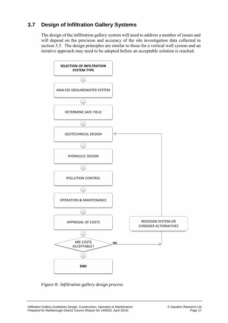
3.7 Design of Infiltration Gallery Systems
The design of the infiltration gallery system will need to address a number of issues and will depend on the precision and accuracy of the site investigation data collected in section 3.5. The design principles are similar to those for a vertical well system and an iterative approach may need to be adopted before an acceptable solution is reached.
Figure 8: Infiltration gallery design process
SELECTION OF INFILTRATION SYSTEM TYPE
ANALYSE GROUNDWATER SYSTEM
DETERMINE SAFE YIELD
GEOTECHNICAL DESIGN
HYDRAULIC DESIGN
POLLUTION CONTROL
OPERATION & MAINTENANCE
APPRAISAL OF COSTS
ARE COSTS ACCEPTABLE?
END
REDESIGN SYSTEM OR CONSIDER ALTERNATIVES
NO
Infiltration Gallery Guidelines Design, Construction, Operation & Maintenance © Aqualinc Research Ltd Prepared for Marlborough District Council (Report No 14003/2, April 2014) Page 18
3.7.1 Analyse Groundwater System
The way in which the ground and groundwater interact must be clearly defined. This can be achieved through the use of a conceptual model.
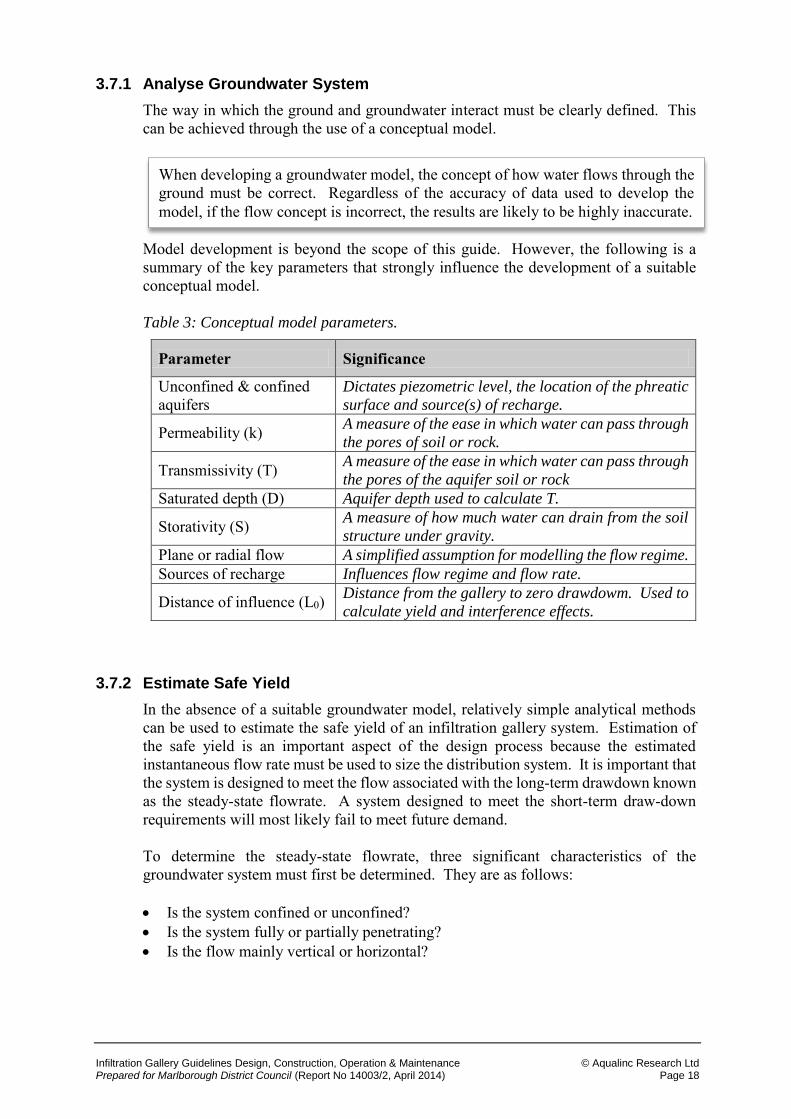
Model development is beyond the scope of this guide. However, the following is a summary of the key parameters that strongly influence the development of a suitable conceptual model. Table 3: Conceptual model parameters.
Parameter Significance
Unconfined & confined aquifers
Dictates piezometric level, the location of the phreatic
surface and source(s) of recharge.
Permeability (k) A measure of the ease in which water can pass through
the pores of soil or rock.
Transmissivity (T) A measure of the ease in which water can pass through
the pores of the aquifer soil or rock
Saturated depth (D) Aquifer depth used to calculate T.
Storativity (S) A measure of how much water can drain from the soil
structure under gravity.
Plane or radial flow A simplified assumption for modelling the flow regime.
Sources of recharge Influences flow regime and flow rate.
Distance of influence (L0) Distance from the gallery to zero drawdowm. Used to
calculate yield and interference effects.
3.7.2 Estimate Safe Yield
In the absence of a suitable groundwater model, relatively simple analytical methods can be used to estimate the safe yield of an infiltration gallery system. Estimation of the safe yield is an important aspect of the design process because the estimated instantaneous flow rate must be used to size the distribution system. It is important that the system is designed to meet the flow associated with the long-term drawdown known as the steady-state flowrate. A system designed to meet the short-term draw-down requirements will most likely fail to meet future demand. To determine the steady-state flowrate, three significant characteristics of the groundwater system must first be determined. They are as follows:
Is the system confined or unconfined? Is the system fully or partially penetrating? Is the flow mainly vertical or horizontal?
When developing a groundwater model, the concept of how water flows through the ground must be correct. Regardless of the accuracy of data used to develop the model, if the flow concept is incorrect, the results are likely to be highly inaccurate.
Infiltration Gallery Guidelines Design, Construction, Operation & Maintenance © Aqualinc Research Ltd Prepared for Marlborough District Council (Report No 14003/2, April 2014) Page 19
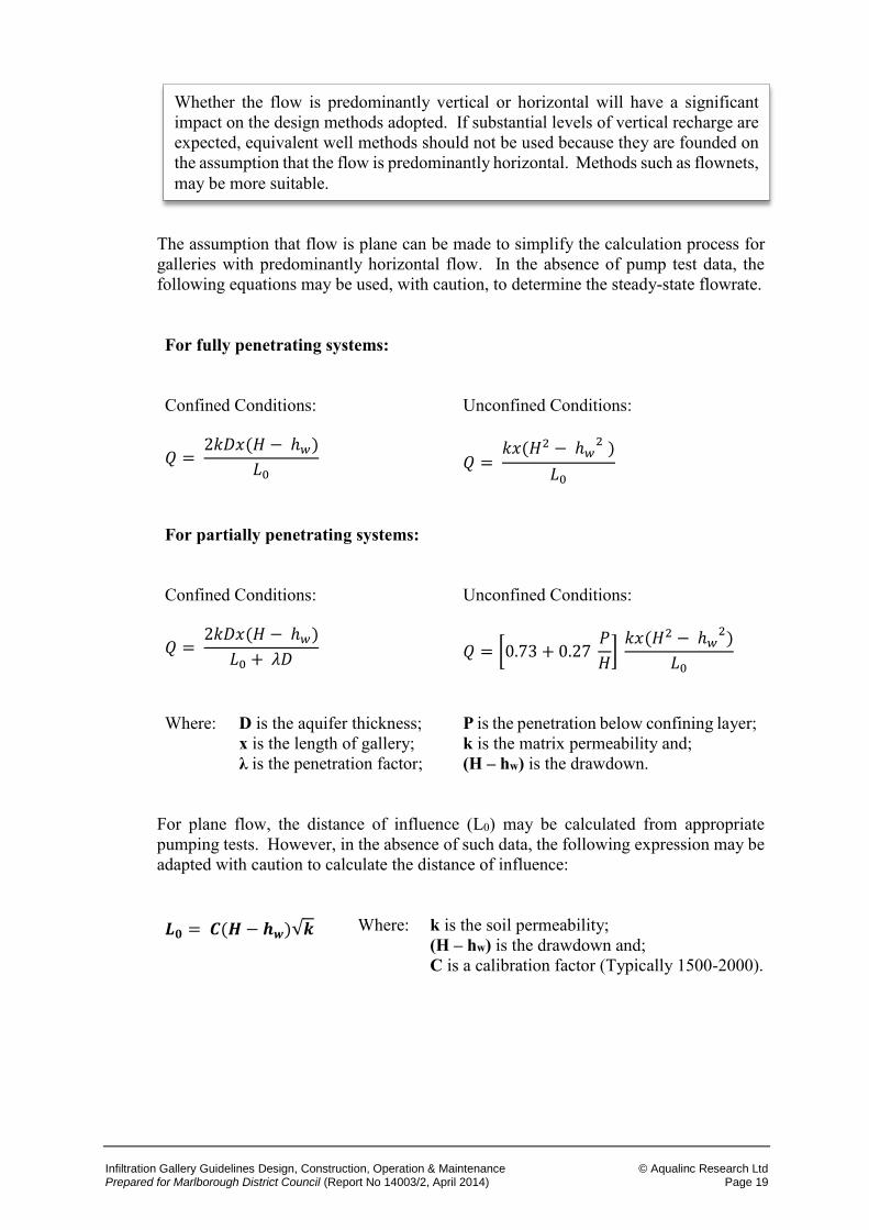
The assumption that flow is plane can be made to simplify the calculation process for galleries with predominantly horizontal flow. In the absence of pump test data, the following equations may be used, with caution, to determine the steady-state flowrate. For fully penetrating systems: Confined Conditions:
Unconfined Conditions:
𝑄 = 2𝑘𝐷𝑥(𝐻 − ℎ𝑤)
𝐿0 𝑄 =
𝑘𝑥(𝐻2 − ℎ𝑤2 )
𝐿0
For partially penetrating systems: Confined Conditions:
Unconfined Conditions:
𝑄 = 2𝑘𝐷𝑥(𝐻 − ℎ𝑤)
𝐿0 + 𝜆𝐷 𝑄 = [0.73 + 0.27
𝑃
𝐻]
𝑘𝑥(𝐻2 − ℎ𝑤2)
𝐿0
Where:
D is the aquifer thickness; x is the length of gallery; λ is the penetration factor;
P is the penetration below confining layer; k is the matrix permeability and; (H – hw) is the drawdown.
For plane flow, the distance of influence (L0) may be calculated from appropriate pumping tests. However, in the absence of such data, the following expression may be adapted with caution to calculate the distance of influence:
𝑳𝟎 = 𝑪(𝑯 − 𝒉𝒘)√𝒌 Where: k is the soil permeability; (H – hw) is the drawdown and; C is a calibration factor (Typically 1500-2000).
Whether the flow is predominantly vertical or horizontal will have a significant impact on the design methods adopted. If substantial levels of vertical recharge are expected, equivalent well methods should not be used because they are founded on the assumption that the flow is predominantly horizontal. Methods such as flownets, may be more suitable.
Infiltration Gallery Guidelines Design, Construction, Operation & Maintenance © Aqualinc Research Ltd Prepared for Marlborough District Council (Report No 14003/2, April 2014) Page 20
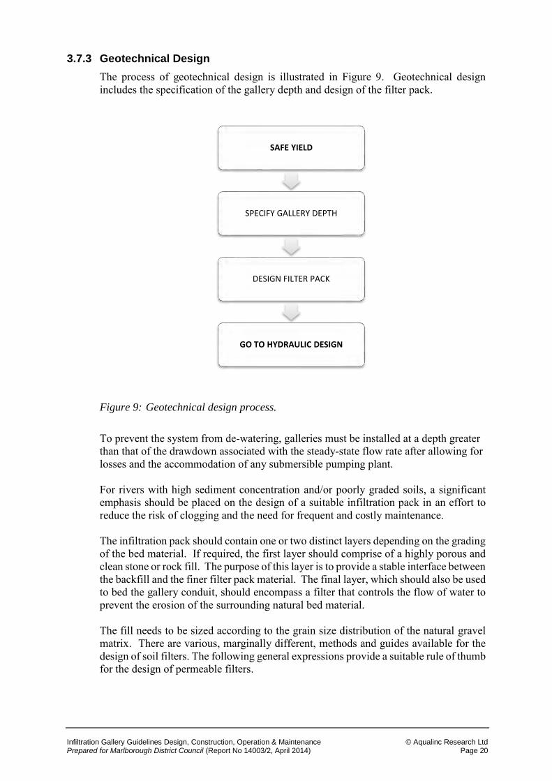
3.7.3 Geotechnical Design
The process of geotechnical design is illustrated in Figure 9. Geotechnical design includes the specification of the gallery depth and design of the filter pack.
Figure 9: Geotechnical design process.
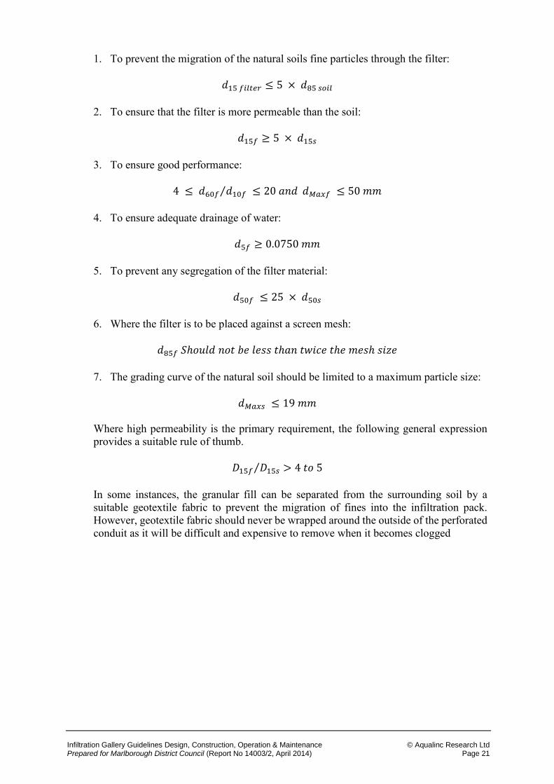
To prevent the system from de-watering, galleries must be installed at a depth greater than that of the drawdown associated with the steady-state flow rate after allowing for losses and the accommodation of any submersible pumping plant. For rivers with high sediment concentration and/or poorly graded soils, a significant emphasis should be placed on the design of a suitable infiltration pack in an effort to reduce the risk of clogging and the need for frequent and costly maintenance. The infiltration pack should contain one or two distinct layers depending on the grading of the bed material. If required, the first layer should comprise of a highly porous and clean stone or rock fill. The purpose of this layer is to provide a stable interface between the backfill and the finer filter pack material. The final layer, which should also be used to bed the gallery conduit, should encompass a filter that controls the flow of water to prevent the erosion of the surrounding natural bed material. The fill needs to be sized according to the grain size distribution of the natural gravel matrix. There are various, marginally different, methods and guides available for the design of soil filters. The following general expressions provide a suitable rule of thumb for the design of permeable filters.
SAFE YIELD
SPECIFY GALLERY DEPTH
DESIGN FILTER PACK
GO TO HYDRAULIC DESIGN
Infiltration Gallery Guidelines Design, Construction, Operation & Maintenance © Aqualinc Research Ltd Prepared for Marlborough District Council (Report No 14003/2, April 2014) Page 21
1. To prevent the migration of the natural soils fine particles through the filter:
𝑑15 𝑓𝑖𝑙𝑡𝑒𝑟 ≤ 5 × 𝑑85 𝑠𝑜𝑖𝑙
2. To ensure that the filter is more permeable than the soil:
𝑑15𝑓 ≥ 5 × 𝑑15𝑠
3. To ensure good performance:
4 ≤ 𝑑60𝑓 𝑑10𝑓 ≤ 20 𝑎𝑛𝑑⁄ 𝑑𝑀𝑎𝑥𝑓 ≤ 50 𝑚𝑚
4. To ensure adequate drainage of water:
𝑑5𝑓 ≥ 0.0750 𝑚𝑚
5. To prevent any segregation of the filter material:
𝑑50𝑓 ≤ 25 × 𝑑50𝑠
6. Where the filter is to be placed against a screen mesh:
𝑑85𝑓 𝑆ℎ𝑜𝑢𝑙𝑑 𝑛𝑜𝑡 𝑏𝑒 𝑙𝑒𝑠𝑠 𝑡ℎ𝑎𝑛 𝑡𝑤𝑖𝑐𝑒 𝑡ℎ𝑒 𝑚𝑒𝑠ℎ 𝑠𝑖𝑧𝑒
7. The grading curve of the natural soil should be limited to a maximum particle size:
𝑑𝑀𝑎𝑥𝑠 ≤ 19 𝑚𝑚
Where high permeability is the primary requirement, the following general expression provides a suitable rule of thumb.
𝐷15𝑓 𝐷15𝑠 > 4 𝑡𝑜 5⁄
In some instances, the granular fill can be separated from the surrounding soil by a suitable geotextile fabric to prevent the migration of fines into the infiltration pack. However, geotextile fabric should never be wrapped around the outside of the perforated conduit as it will be difficult and expensive to remove when it becomes clogged
Infiltration Gallery Guidelines Design, Construction, Operation & Maintenance © Aqualinc Research Ltd Prepared for Marlborough District Council (Report No 14003/2, April 2014) Page 22
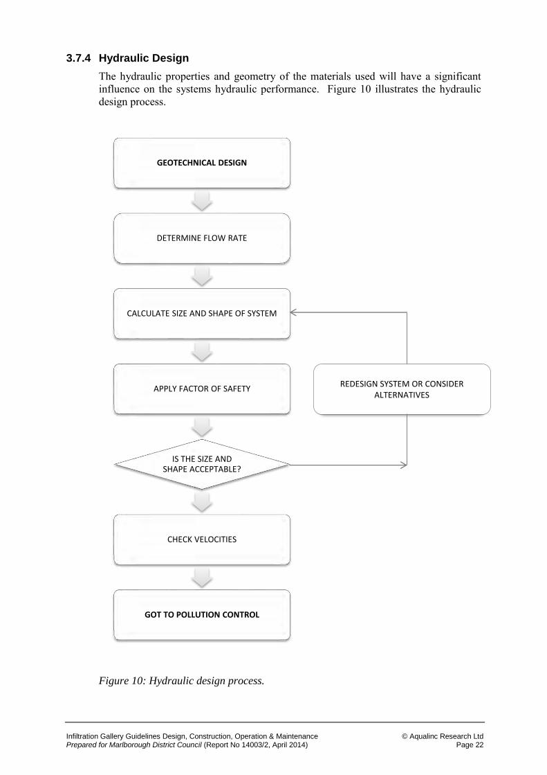
3.7.4 Hydraulic Design
The hydraulic properties and geometry of the materials used will have a significant influence on the systems hydraulic performance. Figure 10 illustrates the hydraulic design process.
Figure 10: Hydraulic design process.
GEOTECHNICAL DESIGN
DETERMINE FLOW RATE
CALCULATE SIZE AND SHAPE OF SYSTEM
APPLY FACTOR OF SAFETY
IS THE SIZE AND SHAPE ACCEPTABLE?
CHECK VELOCITIES
GOT TO POLLUTION CONTROL
REDESIGN SYSTEM OR CONSIDER ALTERNATIVES
Infiltration Gallery Guidelines Design, Construction, Operation & Maintenance © Aqualinc Research Ltd Prepared for Marlborough District Council (Report No 14003/2, April 2014) Page 23
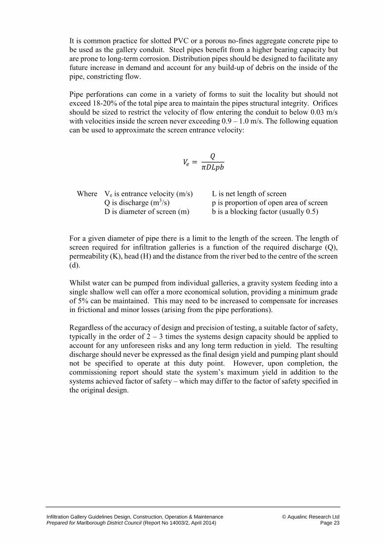
It is common practice for slotted PVC or a porous no-fines aggregate concrete pipe to be used as the gallery conduit. Steel pipes benefit from a higher bearing capacity but are prone to long-term corrosion. Distribution pipes should be designed to facilitate any future increase in demand and account for any build-up of debris on the inside of the pipe, constricting flow. Pipe perforations can come in a variety of forms to suit the locality but should not exceed 18-20% of the total pipe area to maintain the pipes structural integrity. Orifices should be sized to restrict the velocity of flow entering the conduit to below 0.03 m/s with velocities inside the screen never exceeding 0.9 – 1.0 m/s. The following equation can be used to approximate the screen entrance velocity:
𝑉𝑒 = 𝑄
𝜋𝐷𝐿𝑝𝑏
Where Ve is entrance velocity (m/s) L is net length of screen Q is discharge (m3/s) p is proportion of open area of screen D is diameter of screen (m)
b is a blocking factor (usually 0.5)
For a given diameter of pipe there is a limit to the length of the screen. The length of screen required for infiltration galleries is a function of the required discharge (Q), permeability (K), head (H) and the distance from the river bed to the centre of the screen (d). Whilst water can be pumped from individual galleries, a gravity system feeding into a single shallow well can offer a more economical solution, providing a minimum grade of 5% can be maintained. This may need to be increased to compensate for increases in frictional and minor losses (arising from the pipe perforations). Regardless of the accuracy of design and precision of testing, a suitable factor of safety, typically in the order of 2 – 3 times the systems design capacity should be applied to account for any unforeseen risks and any long term reduction in yield. The resulting discharge should never be expressed as the final design yield and pumping plant should not be specified to operate at this duty point. However, upon completion, the commissioning report should state the system’s maximum yield in addition to the systems achieved factor of safety – which may differ to the factor of safety specified in the original design.
Infiltration Gallery Guidelines Design, Construction, Operation & Maintenance © Aqualinc Research Ltd Prepared for Marlborough District Council (Report No 14003/2, April 2014) Page 24
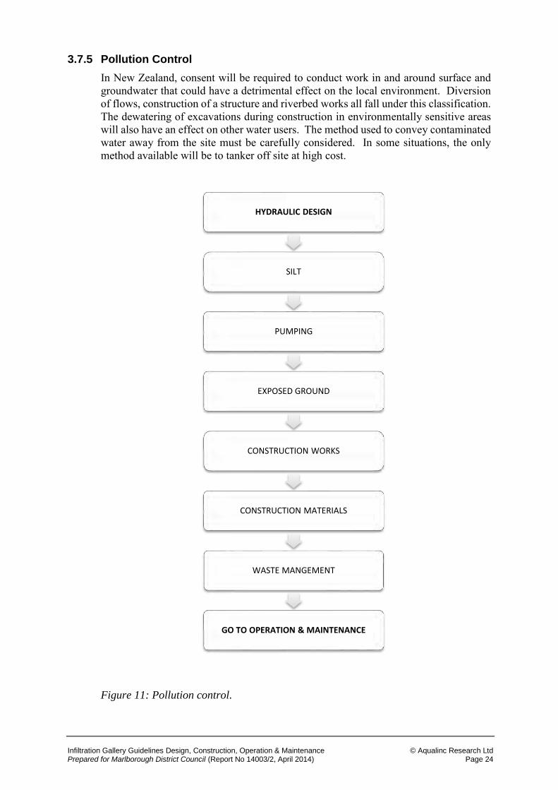
3.7.5 Pollution Control
In New Zealand, consent will be required to conduct work in and around surface and groundwater that could have a detrimental effect on the local environment. Diversion of flows, construction of a structure and riverbed works all fall under this classification. The dewatering of excavations during construction in environmentally sensitive areas will also have an effect on other water users. The method used to convey contaminated water away from the site must be carefully considered. In some situations, the only method available will be to tanker off site at high cost.
Figure 11: Pollution control.
HYDRAULIC DESIGN
SILT
PUMPING
EXPOSED GROUND
CONSTRUCTION WORKS
CONSTRUCTION MATERIALS
WASTE MANGEMENT
GO TO OPERATION & MAINTENANCE
Infiltration Gallery Guidelines Design, Construction, Operation & Maintenance © Aqualinc Research Ltd Prepared for Marlborough District Council (Report No 14003/2, April 2014) Page 25
Silt
Silt pollution damages the local ecosystem by killing aquatic life. The effects of disturbances to the river bed can be minimised through the use of appropriate isolation techniques such as by-pass channels and coffer dams. However, consideration should be given to the riverbed material, likelihood of disturbances and the conditions in which the work is to be conducted. Where possible, silty water pumped from the excavation should be pumped into surface storage and allowed to infiltrate the ground.
Pumping
If excavations are inappropriately designed, water entering the excavation has the potential to become contaminated with harmful pollutants from the works. The most effective method for managing pumping from the excavation is to prevent water from entering through the use of cut off trenches and walls. If this can’t be achieved and water is to enter the trench, consideration should be given to the location of the pump discharge outlet and the rate at which water discharges back into the river, the screening method (if any) to be used on the pump intake to prevent aquatic life from being destroyed and the risk of erosion from discharging.
It is possible to pump directly to farm land, however, permission for this method of disposal must be granted by the council and landowner. The pumping rate must not exceed the soil infiltration rate to prevent surface ponding. This rate will vary with topography, soil type and land use.
Exposed Ground
Ground works that require large areas of soil stripping significantly increase the risk of contaminated surface water run-off. It is therefore important to minimise the area stripped and the amount of vegetation removed. Inappropriately placed spoil and stockpiles can become contaminated from the increase in surface run-off and should be protected accordingly. In sensitive areas, runoff from the area surrounding the site should be collected and stored in surface ponds where suspended fines are allowed to settle prior to disposal.
Filtration tanks provide a cost effective alternative to the use of temporary storage ponds, which can be limited in their use by the available space. Appropriate filter materials in the form of coarse sands, geotextile fabrics or straw bales can be easily sourced and should be frequently cleaned or replaced.
Construction Works
The introduction of construction plant to the site will inevitably generate contaminated water that will need to be treated or disposed of in a controlled manner. Hosing down of plant to remove incrustations should be conducted at least 10 m away from any watercourse.
Infiltration Gallery Guidelines Design, Construction, Operation & Maintenance © Aqualinc Research Ltd Prepared for Marlborough District Council (Report No 14003/2, April 2014) Page 26
Construction Materials
Wash water from concrete or cement should never be allowed to enter the natural environment. Both cement and concrete have a strong alkaline base and can have a serious detrimental effect on the environment. Where possible, recirculation systems should be used to wash down construction plant that has been exposed to these materials, with the water being collected and stored in a sump to facilitate settlement of particle fines.
Strict guidelines govern the use and storage of oil and construction chemicals on site. If required, only small volumes of potentially harmful substances should be stored close to watercourses. Storage must be housed in a secondary containment system on an impermeable material/surface. The storage area must be away from any high risk areas such as a well or spring and located above the flood water level. Provisions such as sand should be put in place and stored close to the hazardous substances for the event of a spill.
Waste Management
Contractors have a legal duty to ensure that any production waste is lawfully disposed of. Waste must be disposed of through an authorised body and be accompanied by a full description of the waste.
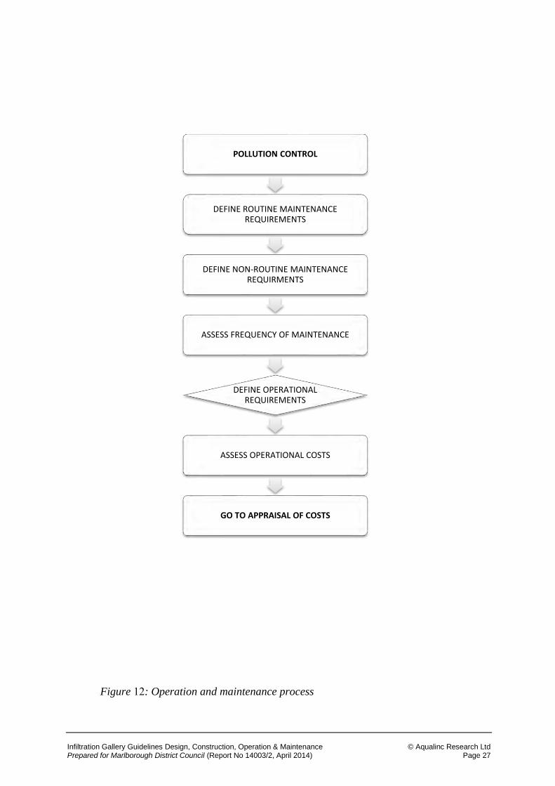
3.7.6 Operation and Maintenance
Regardless of the type of system installed, some form of routine maintenance will need to be conducted to ensure the system does not incur any significant reduction in performance. Most gallery systems will require the filter pack to be cleaned/unblocked. In certain situations, this could virtually amount to completed reconstruction of the gallery system.
Effective maintenance can significantly extend the life of the gallery system. Table 3 is a summary of the routine and non-routine gallery maintenance requirements which may or may not be applicable to any given situation.
Table 4: Routine and non-routine gallery maintenance.
Routine Maintenance Non-routine maintenance
Gallery yield test Replace filter pack Service pump Replace conduit Inspect water quality Replace pump Flush system Corrosion reduction Air blasting
Consideration MUST be given to how the infiltration pack will be cleaned. Compressed air bubblers may be used for vertical drainage systems. However, systems that are dependent on horizontal flow may require a more complex and costly solution.
Infiltration Gallery Guidelines Design, Construction, Operation & Maintenance © Aqualinc Research Ltd Prepared for Marlborough District Council (Report No 14003/2, April 2014) Page 27
Figure 12: Operation and maintenance process
POLLUTION CONTROL
DEFINE ROUTINE MAINTENANCE REQUIREMENTS
DEFINE NON-ROUTINE MAINTENANCE REQUIRMENTS
ASSESS FREQUENCY OF MAINTENANCE
DEFINE OPERATIONAL REQUIREMENTS
ASSESS OPERATIONAL COSTS
GO TO APPRAISAL OF COSTS
Infiltration Gallery Guidelines Design, Construction, Operation & Maintenance © Aqualinc Research Ltd Prepared for Marlborough District Council (Report No 14003/2, April 2014) Page 28
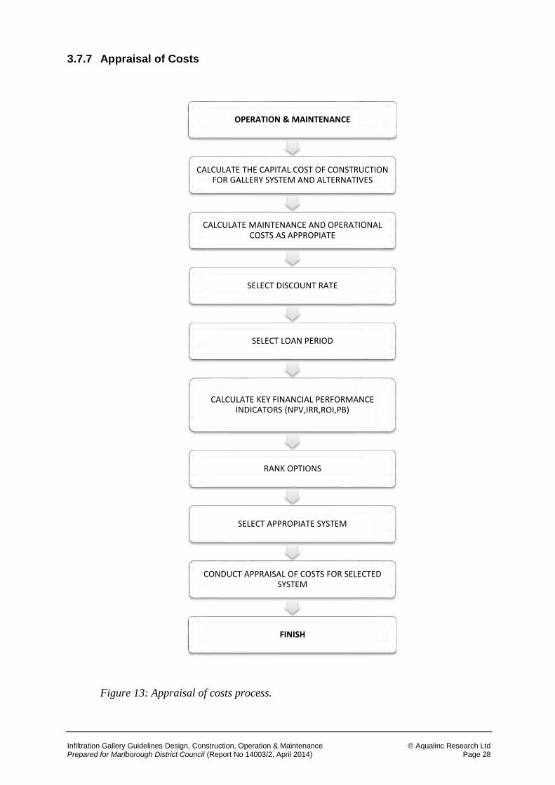
3.7.7 Appraisal of Costs
Figure 13: Appraisal of costs process.
OPERATION & MAINTENANCE
CALCULATE THE CAPITAL COST OF CONSTRUCTION FOR GALLERY SYSTEM AND ALTERNATIVES
CALCULATE MAINTENANCE AND OPERATIONAL COSTS AS APPROPIATE
SELECT DISCOUNT RATE
SELECT LOAN PERIOD
CALCULATE KEY FINANCIAL PERFORMANCE INDICATORS (NPV,IRR,ROI,PB)
RANK OPTIONS
SELECT APPROPIATE SYSTEM
CONDUCT APPRAISAL OF COSTS FOR SELECTED SYSTEM
FINISH
Infiltration Gallery Guidelines Design, Construction, Operation & Maintenance © Aqualinc Research Ltd Prepared for Marlborough District Council (Report No 14003/2, April 2014) Page 29
Infiltration galleries can sometimes offer favourable economies over more traditional intake structures. When making the comparison between the costs associated with infiltration galleries and any alternative solutions, it is important that a holistic approach is taken and that all costs are accounted for. This may even go as far as including the cost of any system enhancements to increase yield or, as a precautionary measure, to offset the uncertainty in ground conditions. Only once this process has been complete can a fair and equitable comparison be made between options.
When considering the costs, an economic or financial view may be taken. The perspective taken will depend on the required result. A financial review will only look at the systems associated capital cost, operating cost and any expected revenues. In contrast, an economic review will investigate the wider costs associated with the system which may include, but is not limited to; the financial impact of system failure on the business or changes to the maintenance cost of systems further down the pipeline. Regardless of the perspective taken, whole life costs must be developed.
Assigning a monetary value to all of the schemes potential advantages and disadvantages can prove quite problematic and subjective. For example, many of the environmental advantages/disadvantages cannot be expressed as a single monetary value but nor should they be ignored.
The calculation of construction costs should be relatively straight forward and can generally be done from unit rates based on historic prices. Recurrent costs include replacement costs, maintenance and repair costs. Infiltration systems require the water to pass though the soil structure prior to entering the distribution system. This process will inevitably draw fine particulate matter into the infiltration pack which will eventually become blinded and need replacing or cleaning. The frequency of replacement will depend on the structures design life which may be considerably shorter than a surface intake. For the purpose of comparison, it will be necessary to allow for replacement costs during the life of the entire reticulation system.
When considering maintenance costs, it is well known that galleries are frequently ignored until failure occurs. Such crisis maintenance is also likely to be expensive, as it may require re-excavation and replacement of much of the horizontal portion of the gallery. It would be a safer option to assume that maintenance is only conducted on a crisis basis, leading to a shorter design life. However, those personnel who do undertake regular maintenance (particularly back blasting), will recognise that regular maintenance will prolong the life of the system.
Infiltration Gallery Guidelines Design, Construction, Operation & Maintenance © Aqualinc Research Ltd Prepared for Marlborough District Council (Report No 14003/2, April 2014) Page 30
4 CONCLUSIONS
1. The purpose of this guide is to promote the use of infiltration gallery systems as one of five possible river intake solutions. The range of options available to the practitioner for diverting river flow and the two main types of infiltration gallery has been set out in this guide, which provides those involved in the planning, appraisal, approval, funding, design, construction operation and maintenance of galleries with the tools to assess the viability of such systems.
2. There is no doubt that the use of infiltration galleries can improve water quality and, if correctly designed and installed, reduce the effects abstraction has on the local environment.
3. Infiltration galleries encourage natural groundwater recharge. Therefore, the rate
of localised groundwater recharge can significantly increase. It must be noted that there is a risk of pollutants entering the groundwater system, from either upstream or construction related sources. This guide provides guidance on reducing these risks.
4. Infiltration galleries require regular maintenance and the correct arrangements must
be made for conducting this.
Top Related