


Languages
Pages
Legal

APPLICATION NOTE
Copyright © 2009, Juniper Networks, Inc. 1
IMPLEMENTING POLICY-BASED IPSEC VPN USING SRX SERIES SERVICES GATEWAYS
2 Copyright © 2009, Juniper Networks, Inc.
APPLICATION NOTE - Implementing Policy-Based IPsec VPN Using SRX Series Services Gateways
Table of Contents
Introduction . . . . . . . . . . . . . . . . . . . . . . . . . . . . . . . . . . . . . . . . . . . . . . . . . . . . . . . . . . . . . . . . . . . . . . . . . . . . . . . . . . . . . . . . . . . . . . . . . . . . 4
Scope . . . . . . . . . . . . . . . . . . . . . . . . . . . . . . . . . . . . . . . . . . . . . . . . . . . . . . . . . . . . . . . . . . . . . . . . . . . . . . . . . . . . . . . . . . . . . . . . . . . . . . . . . . 4
Design Considerations . . . . . . . . . . . . . . . . . . . . . . . . . . . . . . . . . . . . . . . . . . . . . . . . . . . . . . . . . . . . . . . . . . . . . . . . . . . . . . . . . . . . . . . . . . . 4
Problem Scenario . . . . . . . . . . . . . . . . . . . . . . . . . . . . . . . . . . . . . . . . . . . . . . . . . . . . . . . . . . . . . . . . . . . . . . . . . . . . . . . . . . . . . . . . . . . . . 4
Hardware and Software Requirements . . . . . . . . . . . . . . . . . . . . . . . . . . . . . . . . . . . . . . . . . . . . . . . . . . . . . . . . . . . . . . . . . . . . . . . . . 5
Description and Deployment Scenario . . . . . . . . . . . . . . . . . . . . . . . . . . . . . . . . . . . . . . . . . . . . . . . . . . . . . . . . . . . . . . . . . . . . . . . . . . . . 5
Network Diagram . . . . . . . . . . . . . . . . . . . . . . . . . . . . . . . . . . . . . . . . . . . . . . . . . . . . . . . . . . . . . . . . . . . . . . . . . . . . . . . . . . . . . . . . . . . . . 5
Configuration Steps . . . . . . . . . . . . . . . . . . . . . . . . . . . . . . . . . . . . . . . . . . . . . . . . . . . . . . . . . . . . . . . . . . . . . . . . . . . . . . . . . . . . . . . . . . . 5
Basic Steps to Configure . . . . . . . . . . . . . . . . . . . . . . . . . . . . . . . . . . . . . . . . . . . . . . . . . . . . . . . . . . . . . . . . . . . . . . . . . . . . . . . . . . . . . . . 5
Junos OS Configuration . . . . . . . . . . . . . . . . . . . . . . . . . . . . . . . . . . . . . . . . . . . . . . . . . . . . . . . . . . . . . . . . . . . . . . . . . . . . . . . . . . . . . . . . 6
Configure Interface IP Addresses . . . . . . . . . . . . . . . . . . . . . . . . . . . . . . . . . . . . . . . . . . . . . . . . . . . . . . . . . . . . . . . . . . . . . . . . . . . . . 6
Configure Default Route . . . . . . . . . . . . . . . . . . . . . . . . . . . . . . . . . . . . . . . . . . . . . . . . . . . . . . . . . . . . . . . . . . . . . . . . . . . . . . . . . . . . . 6
Configure Security Zones and Assign Interfaces to the Zones . . . . . . . . . . . . . . . . . . . . . . . . . . . . . . . . . . . . . . . . . . . . . . . . . . 6
Configure Host-Inbound Services for Each Zone . . . . . . . . . . . . . . . . . . . . . . . . . . . . . . . . . . . . . . . . . . . . . . . . . . . . . . . . . . . . . . 6
Configure Address Book Entries for Each Zone . . . . . . . . . . . . . . . . . . . . . . . . . . . . . . . . . . . . . . . . . . . . . . . . . . . . . . . . . . . . . . . . 6
Configure IKE Policy for Main Mode, Standard Proposal-Set, and Pre-Shared Key . . . . . . . . . . . . . . . . . . . . . . . . . . . . . . . 6
Configure IKE Gateway (Phase 1) with Peer IP Address, IKE Policy, and Outgoing Interface. . . . . . . . . . . . . . . . . . . . . . . .7
Configure IPsec Policy for Standard Proposal Set . . . . . . . . . . . . . . . . . . . . . . . . . . . . . . . . . . . . . . . . . . . . . . . . . . . . . . . . . . . . . .7
Configure IPsec VPN with IKE Gateway and IPsec Policy . . . . . . . . . . . . . . . . . . . . . . . . . . . . . . . . . . . . . . . . . . . . . . . . . . . . . . . .7
Configure VPN Bidirectional Security Policies for Tunnel Traffic . . . . . . . . . . . . . . . . . . . . . . . . . . . . . . . . . . . . . . . . . . . . . . . . .7
Configure Security Policy for Internet Traffic . . . . . . . . . . . . . . . . . . . . . . . . . . . . . . . . . . . . . . . . . . . . . . . . . . . . . . . . . . . . . . . . . . 8
Configure Tcp-mss to Eliminate Fragmentation of TCP Traffic Across Tunnel . . . . . . . . . . . . . . . . . . . . . . . . . . . . . . . . . . . 8
SSG Series Configuration Example . . . . . . . . . . . . . . . . . . . . . . . . . . . . . . . . . . . . . . . . . . . . . . . . . . . . . . . . . . . . . . . . . . . . . . . . . . . . . 8
Configuration Example for SSG5 . . . . . . . . . . . . . . . . . . . . . . . . . . . . . . . . . . . . . . . . . . . . . . . . . . . . . . . . . . . . . . . . . . . . . . . . . . . . 8
Verifying VPN Connection . . . . . . . . . . . . . . . . . . . . . . . . . . . . . . . . . . . . . . . . . . . . . . . . . . . . . . . . . . . . . . . . . . . . . . . . . . . . . . . . . . . . . . 9
Confirm IKE (Phase 1) Status . . . . . . . . . . . . . . . . . . . . . . . . . . . . . . . . . . . . . . . . . . . . . . . . . . . . . . . . . . . . . . . . . . . . . . . . . . . . . . . . 9
Confirm IPsec (Phase 2) Status . . . . . . . . . . . . . . . . . . . . . . . . . . . . . . . . . . . . . . . . . . . . . . . . . . . . . . . . . . . . . . . . . . . . . . . . . . . . . .10
Check Statistics and Errors for an IPsec SA . . . . . . . . . . . . . . . . . . . . . . . . . . . . . . . . . . . . . . . . . . . . . . . . . . . . . . . . . . . . . . . . . . . 11
Test Traffic Flow Across the VPN . . . . . . . . . . . . . . . . . . . . . . . . . . . . . . . . . . . . . . . . . . . . . . . . . . . . . . . . . . . . . . . . . . . . . . . . . . . . . 11
Troubleshooting Basics . . . . . . . . . . . . . . . . . . . . . . . . . . . . . . . . . . . . . . . . . . . . . . . . . . . . . . . . . . . . . . . . . . . . . . . . . . . . . . . . . . . . . . . . 12
Checking Traceoption Logs . . . . . . . . . . . . . . . . . . . . . . . . . . . . . . . . . . . . . . . . . . . . . . . . . . . . . . . . . . . . . . . . . . . . . . . . . . . . . . . . . . 12
Troubleshooting IKE and IPsec Issues. . . . . . . . . . . . . . . . . . . . . . . . . . . . . . . . . . . . . . . . . . . . . . . . . . . . . . . . . . . . . . . . . . . . . . . . . . . 13
Enable IKE Traceoptions for Phase 1 and Phase 2 Negotiation Issues . . . . . . . . . . . . . . . . . . . . . . . . . . . . . . . . . . . . . . . . . . . 13
Review Kmd Log for Success/Failure Messages . . . . . . . . . . . . . . . . . . . . . . . . . . . . . . . . . . . . . . . . . . . . . . . . . . . . . . . . . . . . . . . 13
Phase 1 and Phase 2 Successful . . . . . . . . . . . . . . . . . . . . . . . . . . . . . . . . . . . . . . . . . . . . . . . . . . . . . . . . . . . . . . . . . . . . . . . . . . . . . 14
Phase 1 Failing to Complete (Example 1) . . . . . . . . . . . . . . . . . . . . . . . . . . . . . . . . . . . . . . . . . . . . . . . . . . . . . . . . . . . . . . . . . . . . . 14
Phase 1 Failing to Complete (Example 2) . . . . . . . . . . . . . . . . . . . . . . . . . . . . . . . . . . . . . . . . . . . . . . . . . . . . . . . . . . . . . . . . . . . . . 14
Phase 1 Failing to Complete (Example 3) . . . . . . . . . . . . . . . . . . . . . . . . . . . . . . . . . . . . . . . . . . . . . . . . . . . . . . . . . . . . . . . . . . . . . 14
Phase 1 Successful, Phase 2 Failing to Complete (Example 1) . . . . . . . . . . . . . . . . . . . . . . . . . . . . . . . . . . . . . . . . . . . . . . . . . . 15
Copyright © 2009, Juniper Networks, Inc. 3
APPLICATION NOTE - Implementing Policy-Based IPsec VPN Using SRX Series Services Gateways
Table of Figures
Figure 1: Network topology . . . . . . . . . . . . . . . . . . . . . . . . . . . . . . . . . . . . . . . . . . . . . . . . . . . . . . . . . . . . . . . . . . . . . . . . . . . . . . . . . . . . . . . 5
Phase 1 Successful, Phase 2 Failing to Complete (Example 2) . . . . . . . . . . . . . . . . . . . . . . . . . . . . . . . . . . . . . . . . . . . . . . . . . 15
Troubleshooting Flow Issues . . . . . . . . . . . . . . . . . . . . . . . . . . . . . . . . . . . . . . . . . . . . . . . . . . . . . . . . . . . . . . . . . . . . . . . . . . . . . . . . . . . 15
Problem Scenario . . . . . . . . . . . . . . . . . . . . . . . . . . . . . . . . . . . . . . . . . . . . . . . . . . . . . . . . . . . . . . . . . . . . . . . . . . . . . . . . . . . . . . . . . . . 15
Enabling Security Flow Traceoptions for Routing or Policy Issues . . . . . . . . . . . . . . . . . . . . . . . . . . . . . . . . . . . . . . . . . . . . . . .16
Validating First Problem Statement . . . . . . . . . . . . . . . . . . . . . . . . . . . . . . . . . . . . . . . . . . . . . . . . . . . . . . . . . . . . . . . . . . . . . . . . . .18
Troubleshooting Second Problem Statement . . . . . . . . . . . . . . . . . . . . . . . . . . . . . . . . . . . . . . . . . . . . . . . . . . . . . . . . . . . . . . . . . 21
Appendix A: Show Configuration . . . . . . . . . . . . . . . . . . . . . . . . . . . . . . . . . . . . . . . . . . . . . . . . . . . . . . . . . . . . . . . . . . . . . . . . . . . . . . . . 24
About Juniper Networks . . . . . . . . . . . . . . . . . . . . . . . . . . . . . . . . . . . . . . . . . . . . . . . . . . . . . . . . . . . . . . . . . . . . . . . . . . . . . . . . . . . . . . . . . 27
4 Copyright © 2009, Juniper Networks, Inc.
APPLICATION NOTE - Implementing Policy-Based IPsec VPN Using SRX Series Services Gateways
Introduction
Juniper Networks® Junos® operating system runs on Juniper Networks J Series Services Routers and Juniper Networks
SRX Series Services Gateways. It provides not only a powerful operating system, but also a rich IP services tool kit for
these platforms. Junos OS has enhanced security and VPN capabilities via Juniper’s firewall/IPsec VPN platforms,
which include the Juniper Networks SSG Series Secure Services Gateways. The purpose of this application note is to
detail IPsec interoperability configuration between a Junos OS-based device and an SSG Series device. This application
note also includes troubleshooting information for Junos OS.
Scope
This document describes configuration and troubleshooting basics for the implementation of policy-based IPsec VPN
using SRX Series gateways. It is applicable to the SRX Series, as well as the J Series running Junos OS 9.4 and above or
running Junos OS with Enhanced Services 8.5 through 9.3.
This document is intended for network design and security engineers, as well as implementation partners who support
customers requiring secure connectivity over public networks.
Design Considerations
The configuration of a Junos OS-based routing/security device for VPN support is quite flexible, allowing you to create
route-based and policy-based VPN tunnels. This application note focuses on policy-based VPN tunnels, but it is first
important to understand the differences between the two and why one method may be recommended over the other.
Problem Scenario
With policy-based VPN tunnels, a tunnel is treated as an object which, together with source, destination, application,
and action, comprises a tunnel policy that permits VPN traffic. In a policy-based VPN configuration, a tunnel policy
specifically references a VPN tunnel by name. With route-based VPNs, a policy does not specifically reference a VPN
tunnel but instead references a destination address. When the security device does a route lookup to find the interface
through which it must send traffic to reach that address, it finds a route via a secure tunnel (st0) interface, which
is bound to a specific VPN tunnel. With a policy-based VPN tunnel, you can consider a tunnel as an element in the
construction of a policy. With a route-based VPN tunnel, you can consider a tunnel as a means for delivering traffic,
and the policy as a method for either permitting or denying the delivery of that traffic.
The number of policy-based VPN tunnels that you can create is limited by the number of policies that the device
supports. The number of route-based VPN tunnels that you create is limited by the number of route entries or the
number of st0 interfaces that the device supports—whichever number is lower. A route-based VPN tunnel configuration
is a good choice when you want to conserve tunnel resources while setting granular restrictions on VPN traffic.
Although you can create numerous tunnel policies referencing the same VPN tunnel with a policy-based VPN, each
tunnel policy pair creates an individual IPsec security association (SA) with the remote peer. Each SA counts as an
individual VPN tunnel. With a route-based approach to VPNs, on the other hand, the regulation of traffic is not coupled
to the means of its delivery. You can configure dozens of policies to regulate traffic flowing through a single VPN
tunnel between two sites, and there is just one IPsec SA at work. A route-based VPN configuration allows you to create
policies referencing a destination reached through a VPN tunnel in which the action is “deny.” This is unlike a policy-
based VPN configuration in which the action must be “permit” and include the tunnel.
Another advantage that route-based VPNs offer is the exchange of dynamic routing information through VPN
tunnels. This is not supported with policy-based VPNs. For hub-and-spoke topologies, you must use a route-based
configuration. Lastly, you can define static Network Address Translation (NAT) addresses specifically for st0 interfaces.
OSPF, hub-and-spoke, and static NAT configurations are beyond the scope of this application note.
When a tunnel does not connect large networks running dynamic routing protocols, and you do not need to conserve
tunnels or define various policies to filter traffic through the tunnel, a policy-based tunnel makes sense. Also, because
there is no network beyond a dialup VPN client, policy-based VPN tunnels can be a good choice for dialup VPN
configurations. Finally, for interoperability with third-party vendors that do not support the concept of route-based
VPNs, policy-based VPNs may be absolutely required, particularly if that third party requires separate SAs for each
remote subnet.
For the purposes of this application note, we focus on policy-based VPN configuration and troubleshooting. Additional
Junos OS-specific application notes can be found on Juniper Networks’ Knowledge Base at http://kb.juniper.net. In
particular, article KB10182 lists several application notes related to VPN configuration and troubleshooting.
Copyright © 2009, Juniper Networks, Inc. 5
APPLICATION NOTE - Implementing Policy-Based IPsec VPN Using SRX Series Services Gateways
Hardware and Software Requirements
• J Series Services Routers running Junos OS 9.4 and above
• J Series Service Routers running Junos OS with Enhanced Services 8.5 through 9.3
• SRX Series Services Gateways
• SSG Series Secure Services Gateways
Description and Deployment Scenario
Network Diagram
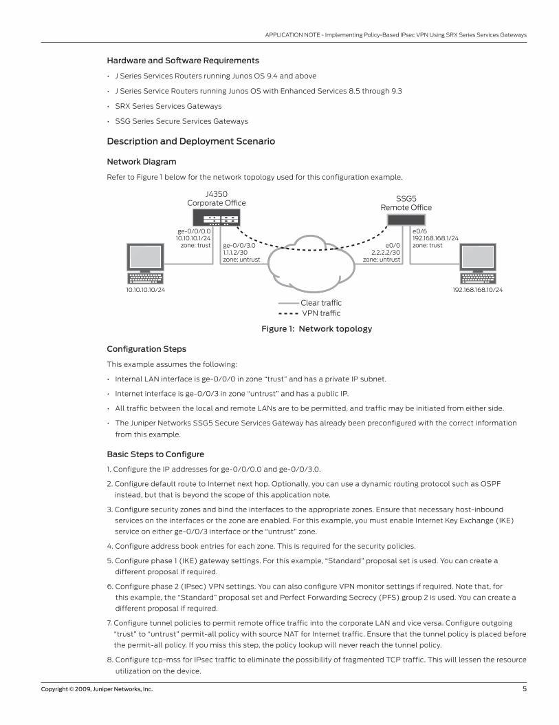
Refer to Figure 1 below for the network topology used for this configuration example.
Figure 1: Network topology
Configuration Steps
This example assumes the following:
• Internal LAN interface is ge-0/0/0 in zone “trust” and has a private IP subnet.
• Internet interface is ge-0/0/3 in zone “untrust” and has a public IP.
• All traffic between the local and remote LANs are to be permitted, and traffic may be initiated from either side.
• The Juniper Networks SSG5 Secure Services Gateway has already been preconfigured with the correct information
from this example.
Basic Steps to Configure
1. Configure the IP addresses for ge-0/0/0.0 and ge-0/0/3.0.
2. Configure default route to Internet next hop. Optionally, you can use a dynamic routing protocol such as OSPF
instead, but that is beyond the scope of this application note.
3. Configure security zones and bind the interfaces to the appropriate zones. Ensure that necessary host-inbound
services on the interfaces or the zone are enabled. For this example, you must enable Internet Key Exchange (IKE)
service on either ge-0/0/3 interface or the “untrust” zone.
4. Configure address book entries for each zone. This is required for the security policies.
5. Configure phase 1 (IKE) gateway settings. For this example, “Standard” proposal set is used. You can create a
different proposal if required.
6. Configure phase 2 (IPsec) VPN settings. You can also configure VPN monitor settings if required. Note that, for
this example, the “Standard” proposal set and Perfect Forwarding Secrecy (PFS) group 2 is used. You can create a
different proposal if required.
7. Configure tunnel policies to permit remote office traffic into the corporate LAN and vice versa. Configure outgoing
“trust” to “untrust” permit-all policy with source NAT for Internet traffic. Ensure that the tunnel policy is placed before
the permit-all policy. If you miss this step, the policy lookup will never reach the tunnel policy.
8. Configure tcp-mss for IPsec traffic to eliminate the possibility of fragmented TCP traffic. This will lessen the resource
utilization on the device.
J4350Corporate O�ce SSG5
Remote O�ce
ge-0/0/0.010.10.10.1/24
zone: trust ge-0/0/3.01.1.1.2/30zone: untrust
10.10.10.10/24 192.168.168.10/24
e0/02.2.2.2/30
zone: untrust
e0/6192.168.168.1/24zone: trust
Clear tra�cVPN tra�c

6 Copyright © 2009, Juniper Networks, Inc.
APPLICATION NOTE - Implementing Policy-Based IPsec VPN Using SRX Series Services Gateways
Junos OS Configuration
To begin, enter configuration mode with either the “configure” or the ”edit” command.
Configure Interface IP Addresses
set interfaces ge-0/0/0 unit 0 family inet address 10.10.10.1/24set interfaces ge-0/0/3 unit 0 family inet address 1.1.1.2/30
Junos OS uses the concept of units for the logical component of an interface. In this example, unit 0 and family inet
(IPv4) are used.
Configure Default Route
set routing-options static route 0.0.0.0/0 next-hop 1.1.1.1
When processing the first packet of a new session, the Junos OS-based device performs a route lookup. The static
route shown above, which happens to be the default route, dictates what zone the VPN traffic must egress. In this
example, the VPN traffic ingresses on interface ge-0/0/0.0 with the next hop of 1.1.1.1. The traffic egresses out interface
ge-0/0/3.0. Any tunnel policy must take into account ingress and egress interfaces.
Configure Security Zones and Assign Interfaces to the Zones
set security zones security-zone trust interfaces ge-0/0/0.0set security zones security-zone untrust interfaces ge-0/0/3.0
The ingress and egress zones are determined by the ingress and egress interfaces involved in the route lookup. As
shown above, packets ingressing on ge-0/0/0 mean that the ingress zone is a “trust” zone. Following the route lookup,
the egress interface is ge-0/0/3 and the egress zone is an “untrust” zone. The tunnel policy must be “from-zone trust
to-zone untrust” and vice versa.
Configure Host-Inbound Services for Each Zone
set security zones security-zone trust host-inbound-traffic system-services allset security zones security-zone untrust host-inbound-traffic system-services ike
Host-inbound services are for traffic destined for the Junos OS-based device. This includes but is not limited to FTP,
HTTP, HTTPS, IKE, ping, rlogin, RSH, SNMP, SSH, Telnet, Trivial File Transfer Protocol (TFTP), and traceroute. For
this example, all such services from zone “trust” are allowed. For security reasons, we only allow IKE on the Internet
facing zone “untrust” which is required for IKE negotiations to occur. Other services, such as for management or
troubleshooting, can be individually enabled if required.
Configure Address Book Entries for Each Zone
set security zones security-zone trust address-book address local-net 10.10.10.0/24set security zones security-zone untrust address-book address remote-net 192.168.168.0/24
For this example, address book object names “local-net” and “remote-net” are used. There are some limitations with
regards to which characters are supported for address book names. Please refer to complete Junos OS documentation
for more details.
Configure IKE Policy for Main Mode, Standard Proposal-Set, and Pre-Shared Key
set security ike policy ike-policy1 mode mainset security ike policy ike-policy1 proposal-set standardset security ike policy ike-policy1 pre-shared-key ascii-text “secretkey”
For the purposes of this application note, we use the “Standard” proposal set that includes “preshared-group2-3des-
sha1” and “preshared-group2-aes128-sha1” proposals. A unique proposal can be created and specified in the IKE policy
in accordance with your corporate security policy.

Copyright © 2009, Juniper Networks, Inc. 7
APPLICATION NOTE - Implementing Policy-Based IPsec VPN Using SRX Series Services Gateways
Configure IKE Gateway (Phase 1) with Peer IP Address, IKE Policy, and Outgoing Interface
set security ike gateway ike-gate ike-policy ike-policy1set security ike gateway ike-gate address 2.2.2.2set security ike gateway ike-gate external-interface ge-0/0/3.0
A remote IKE peer can be identified by IP address, FQDN/u-FQDN, or ASN1-DN (PKI certificates). For this example, the
peer is identified by IP address. Therefore, the gateway address should be the remote peer’s public IP address. It is
important to specify the correct external interface. If either the peer address or external interface specified is incorrect,
the IKE gateway will not be properly identified during phase 1 negotiations.
Configure IPsec Policy for Standard Proposal Set
set security ipsec policy vpn-policy1 proposal-set standard
As mentioned for phase 1, we are using ”Standard” proposal set which includes “esp-group2-3des-sha1” and “esp-
group2-aes128-sha1” proposals for the purposes of this application note. A unique proposal can be created and
specified in the IPsec policy, if required.
Configure IPsec VPN with IKE Gateway and IPsec Policy
set security ipsec vpn ike-vpn ike gateway ike-gateset security ipsec vpn ike-vpn ike ipsec-policy vpn-policy1
For this example, the VPN name “ike-vpn” must be referenced in the security policy to be able to create a security
association.
Configure VPN Bidirectional Security Policies for Tunnel Traffic
edit security policies from-zone trust to-zone untrust ## Enter zone “trust” to zone “untrust” hierarchyset policy vpnpolicy-tr-unt match source-address local-netset policy vpnpolicy-tr-unt match destination-address remote-netset policy vpnpolicy-tr-unt match application anyset policy vpnpolicy-tr-unt then permit tunnel ipsec-vpn ike-vpnset policy vpnpolicy-tr-unt then permit tunnel pair-policy vpnpolicy-unt-tr
edit security policies from-zone untrust to-zone trust ## Enter zone “untrust” to zone “trust” hierarchyset policy vpnpolicy-unt-tr match source-address remote-netset policy vpnpolicy-unt-tr match destination-address local-netset policy vpnpolicy-unt-tr match application anyset policy vpnpolicy-unt-tr then permit tunnel ipsec-vpn ike-vpnset policy vpnpolicy-unt-tr then permit tunnel pair-policy vpnpolicy-tr-untexit
For this example, traffic from the corporate LAN to the remote office LAN requires a “from-zone trust to-zone untrust”
tunnel policy. If a session must originate from the remote LAN to the corporate LAN, a tunnel policy in the opposite
direction “from-zone untrust to-zone trust” is required. By specifying pair policy, the VPN becomes bidirectional. Note
in addition to the action “permit,” the IPsec profile must be specified. Furthermore, source NAT can be enabled on the
policy if desired, but that is beyond the scope of this application note. Note that for tunnel policies, the action is always
“permit.” If configuring a policy with an action of “deny,” you will not see an option for specifying the tunnel.
8 Copyright © 2009, Juniper Networks, Inc.
APPLICATION NOTE - Implementing Policy-Based IPsec VPN Using SRX Series Services Gateways
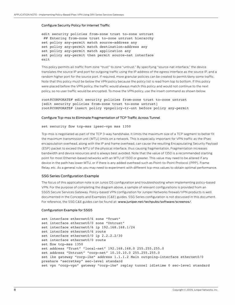
Configure Security Policy for Internet Traffic
edit security policies from-zone trust to-zone untrust ## Entering from-zone trust to-zone untrust hierarchyset policy any-permit match source-address anyset policy any-permit match destination-address anyset policy any-permit match application anyset policy any-permit then permit source-nat interfaceexit
This policy permits all traffic from zone “trust” to zone “untrust.” By specifying “source-nat interface,” the device
translates the source IP and port for outgoing traffic using the IP address of the egress interface as the source IP, and a
random higher port for the source port. If required, more granular policies can be created to permit/deny some traffic.
Note that this policy must be below the VPN policy because the policy list is read from top to bottom. If this policy
were placed before the VPN policy, the traffic would always match this policy and would not continue to the next
policy, so no user traffic would be encrypted. To move the VPN policy, use the insert command as shown below.
root@CORPORATE# edit security policies from-zone trust to-zone untrust[edit security policies from-zone trust to-zone untrust]root@CORPORATE# insert policy vpnpolicy-tr-unt before policy any-permit
Configure Tcp-mss to Eliminate Fragmentation of TCP Traffic Across Tunnel
set security flow tcp-mss ipsec-vpn mss 1350
Tcp-mss is negotiated as part of the TCP 3-way handshake. It limits the maximum size of a TCP segment to better fit
the maximum transmission unit (MTU) limits on a network. This is especially important for VPN traffic as the IPsec
encapsulation overhead, along with the IP and frame overhead, can cause the resulting Encapsulating Security Payload
(ESP) packet to exceed the MTU of the physical interface, thus causing fragmentation. Fragmentation increases
bandwidth and device resources and is always best avoided. Note that the value of 1350 is a recommended starting
point for most Ethernet-based networks with an MTU of 1500 or greater. This value may need to be altered if any
device in the path has lower MTU, or if there is any added overhead such as Point-to-Point Protocol (PPP), Frame
Relay, etc. As a general rule, you may need to experiment with different tcp-mss values to obtain optimal performance.
SSG Series Configuration Example
The focus of this application note is on Junos OS configuration and troubleshooting when implementing policy-based
VPN. For the purpose of completing the diagram above, a sample of relevant configurations is provided from an
SSG5 Secure Services Gateway. Policy-based VPN configuration for Juniper Networks firewall/VPN products is well
documented in the Concepts and Examples (C&E) guides. SSG Series configuration is not discussed in this document.
For reference, the SSG C&E guides can be found at: www.juniper.net/techpubs/software/screenos/.
Configuration Example for SSG5
set interface ethernet0/6 zone “Trust”set interface ethernet0/0 zone “Untrust”set interface ethernet0/6 ip 192.168.168.1/24set interface ethernet0/6 routeset interface ethernet0/0 ip 2.2.2.2/30set interface ethernet0/0 routeset flow tcp-mss 1350set address “Trust” “local-net” 192.168.168.0 255.255.255.0set address “Untrust” “corp-net” 10.10.10.0 255.255.255.0set ike gateway “corp-ike” address 1.1.1.2 Main outgoing-interface ethernet0/0 preshare “secretkey” sec-level standardset vpn “corp-vpn” gateway “corp-ike” replay tunnel idletime 0 sec-level standard
Copyright © 2009, Juniper Networks, Inc. 9
APPLICATION NOTE - Implementing Policy-Based IPsec VPN Using SRX Series Services Gateways
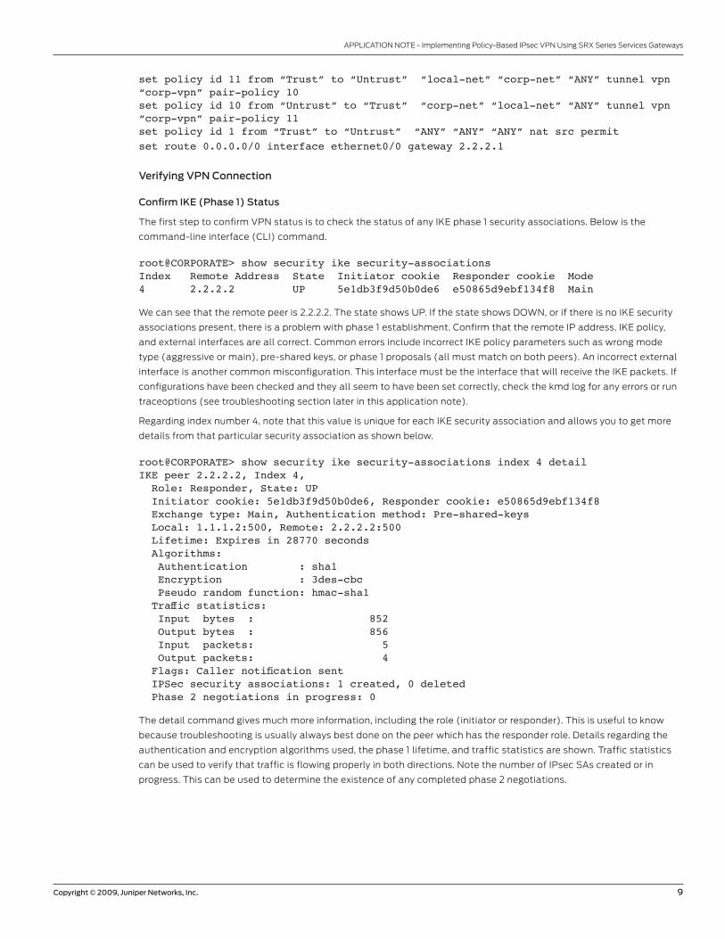
set policy id 11 from “Trust” to “Untrust” “local-net” “corp-net” “ANY” tunnel vpn “corp-vpn” pair-policy 10 set policy id 10 from “Untrust” to “Trust” “corp-net” “local-net” “ANY” tunnel vpn “corp-vpn” pair-policy 11set policy id 1 from “Trust” to “Untrust” “ANY” “ANY” “ANY” nat src permit set route 0.0.0.0/0 interface ethernet0/0 gateway 2.2.2.1
Verifying VPN Connection
Confirm IKE (Phase 1) Status
The first step to confirm VPN status is to check the status of any IKE phase 1 security associations. Below is the
command-line interface (CLI) command.
root@CORPORATE> show security ike security-associations Index Remote Address State Initiator cookie Responder cookie Mode4 2.2.2.2 UP 5e1db3f9d50b0de6 e50865d9ebf134f8 Main
We can see that the remote peer is 2.2.2.2. The state shows UP. If the state shows DOWN, or if there is no IKE security
associations present, there is a problem with phase 1 establishment. Confirm that the remote IP address, IKE policy,
and external interfaces are all correct. Common errors include incorrect IKE policy parameters such as wrong mode
type (aggressive or main), pre-shared keys, or phase 1 proposals (all must match on both peers). An incorrect external
interface is another common misconfiguration. This interface must be the interface that will receive the IKE packets. If
configurations have been checked and they all seem to have been set correctly, check the kmd log for any errors or run
traceoptions (see troubleshooting section later in this application note).
Regarding index number 4, note that this value is unique for each IKE security association and allows you to get more
details from that particular security association as shown below.
root@CORPORATE> show security ike security-associations index 4 detail IKE peer 2.2.2.2, Index 4, Role: Responder, State: UP Initiator cookie: 5e1db3f9d50b0de6, Responder cookie: e50865d9ebf134f8 Exchange type: Main, Authentication method: Pre-shared-keys Local: 1.1.1.2:500, Remote: 2.2.2.2:500 Lifetime: Expires in 28770 seconds Algorithms: Authentication : sha1 Encryption : 3des-cbc Pseudo random function: hmac-sha1 Traffic statistics: Input bytes : 852 Output bytes : 856 Input packets: 5 Output packets: 4 Flags: Caller notification sent IPSec security associations: 1 created, 0 deleted Phase 2 negotiations in progress: 0
The detail command gives much more information, including the role (initiator or responder). This is useful to know
because troubleshooting is usually always best done on the peer which has the responder role. Details regarding the
authentication and encryption algorithms used, the phase 1 lifetime, and traffic statistics are shown. Traffic statistics
can be used to verify that traffic is flowing properly in both directions. Note the number of IPsec SAs created or in
progress. This can be used to determine the existence of any completed phase 2 negotiations.
10 Copyright © 2009, Juniper Networks, Inc.
APPLICATION NOTE - Implementing Policy-Based IPsec VPN Using SRX Series Services Gateways
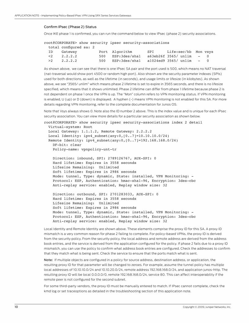
Confirm IPsec (Phase 2) Status
Once IKE phase 1 is confirmed, you can run the command below to view IPsec (phase 2) security associations.
root@CORPORATE> show security ipsec security-associations total configured sa: 2 ID Gateway Port Algorithm SPI Life:sec/kb Mon vsys <2 2.2.2.2 500 ESP:3des/sha1 a63eb26f 3565/ unlim - 0 >2 2.2.2.2 500 ESP:3des/sha1 a1024ed9 3565/ unlim - 0
As shown above, we can see that there is one IPsec SA pair and the port used is 500, which means no NAT traversal
(nat-traversal would show port 4500 or random high port). Also shown are the security parameter indexes (SPIs)
used for both directions, as well as the lifetime (in seconds), and usage limits or lifesize (in kilobytes). As shown
above, we see “3565/ unlim” which means phase 2 lifetime is set to expire in 3565 seconds, and there is no lifesize
specified, which means that it shows unlimited. Phase 2 lifetime can differ from phase 1 lifetime because phase 2 is
not dependent on phase 1 once the VPN is up. The “Mon” column refers to VPN monitoring status. If VPN monitoring
is enabled, U (up) or D (down) is displayed. A hyphen (-) means VPN monitoring is not enabled for this SA. For more
details regarding VPN monitoring, refer to the complete documentation for Junos OS.
Note that Vsys always shows 0. Note also the ID number 2 above. This is the index value and is unique for each IPsec
security association. You can view more details for a particular security association as shown below.
root@CORPORATE> show security ipsec security-associations index 2 detail Virtual-system: Root Local Gateway: 1.1.1.2, Remote Gateway: 2.2.2.2 Local Identity: ipv4_subnet(any:0,[0..7]=10.10.10.0/24) Remote Identity: ipv4_subnet(any:0,[0..7]=192.168.168.0/24) DF-bit: clear Policy-name: vpnpolicy-unt-tr
Direction: inbound, SPI: 2789126767, AUX-SPI: 0 Hard lifetime: Expires in 3558 seconds Lifesize Remaining: Unlimited Soft lifetime: Expires in 2986 seconds Mode: tunnel, Type: dynamic, State: installed, VPN Monitoring: - Protocol: ESP, Authentication: hmac-sha1-96, Encryption: 3des-cbc Anti-replay service: enabled, Replay window size: 32
Direction: outbound, SPI: 2701283033, AUX-SPI: 0 Hard lifetime: Expires in 3558 seconds Lifesize Remaining: Unlimited Soft lifetime: Expires in 2986 seconds Mode: tunnel, Type: dynamic, State: installed, VPN Monitoring: - Protocol: ESP, Authentication: hmac-sha1-96, Encryption: 3des-cbc Anti-replay service: enabled, Replay window size: 32
Local Identity and Remote Identity are shown above. These elements comprise the proxy ID for this SA. A proxy ID
mismatch is a very common reason for phase 2 failing to complete. For policy-based VPNs, the proxy ID is derived
from the security policy. From the security policy, the local address and remote address are derived from the address
book entries, and the service is derived from the application configured for the policy. If phase 2 fails due to a proxy ID
mismatch, you can use the policy to confirm what address book entries are configured. Check the addresses to confirm
that they match what is being sent. Check the service to ensure that the ports match what is sent.
Note: If multiple objects are configured in a policy for source address, destination address, or application, the
resulting proxy ID for that parameter will be changed to zeroes. For example, assume the tunnel policy has multiple
local addresses of 10.10.10.0/24 and 10.10.20.0/24, remote address 192.168.168.0/24, and application junos-http. The
resulting proxy ID will be local 0.0.0.0/0, remote 192.168.168.0/24, service 80. This can affect interoperability if the
remote peer is not configured for the second subnet.
For some third-party vendors, the proxy ID must be manually entered to match. If IPsec cannot complete, check the
kmd log or set traceoptions as detailed in the troubleshooting section of this application note.
Copyright © 2009, Juniper Networks, Inc. 11
APPLICATION NOTE - Implementing Policy-Based IPsec VPN Using SRX Series Services Gateways
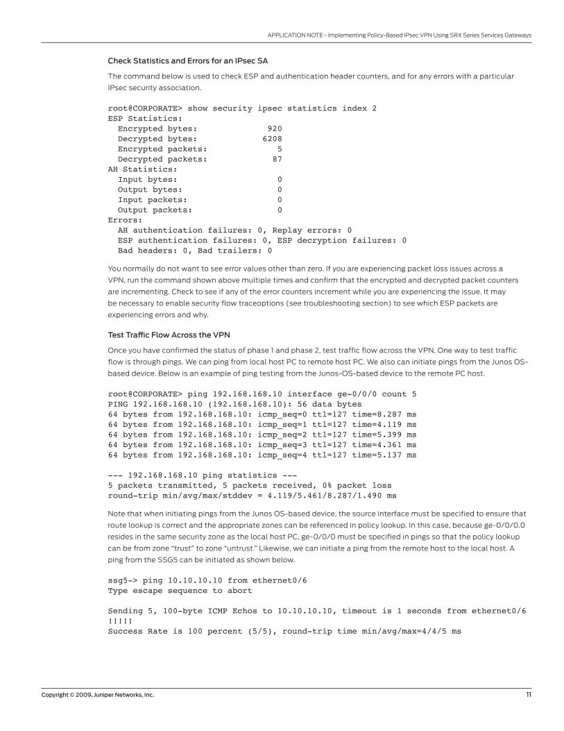
Check Statistics and Errors for an IPsec SA
The command below is used to check ESP and authentication header counters, and for any errors with a particular
IPsec security association.
root@CORPORATE> show security ipsec statistics index 2 ESP Statistics: Encrypted bytes: 920 Decrypted bytes: 6208 Encrypted packets: 5 Decrypted packets: 87AH Statistics: Input bytes: 0 Output bytes: 0 Input packets: 0 Output packets: 0Errors: AH authentication failures: 0, Replay errors: 0 ESP authentication failures: 0, ESP decryption failures: 0 Bad headers: 0, Bad trailers: 0
You normally do not want to see error values other than zero. If you are experiencing packet loss issues across a
VPN, run the command shown above multiple times and confirm that the encrypted and decrypted packet counters
are incrementing. Check to see if any of the error counters increment while you are experiencing the issue. It may
be necessary to enable security flow traceoptions (see troubleshooting section) to see which ESP packets are
experiencing errors and why.
Test Traffic Flow Across the VPN
Once you have confirmed the status of phase 1 and phase 2, test traffic flow across the VPN. One way to test traffic
flow is through pings. We can ping from local host PC to remote host PC. We also can initiate pings from the Junos OS-
based device. Below is an example of ping testing from the Junos-OS-based device to the remote PC host.
root@CORPORATE> ping 192.168.168.10 interface ge-0/0/0 count 5PING 192.168.168.10 (192.168.168.10): 56 data bytes64 bytes from 192.168.168.10: icmp_seq=0 ttl=127 time=8.287 ms64 bytes from 192.168.168.10: icmp_seq=1 ttl=127 time=4.119 ms64 bytes from 192.168.168.10: icmp_seq=2 ttl=127 time=5.399 ms64 bytes from 192.168.168.10: icmp_seq=3 ttl=127 time=4.361 ms64 bytes from 192.168.168.10: icmp_seq=4 ttl=127 time=5.137 ms
--- 192.168.168.10 ping statistics ---5 packets transmitted, 5 packets received, 0% packet lossround-trip min/avg/max/stddev = 4.119/5.461/8.287/1.490 ms
Note that when initiating pings from the Junos OS-based device, the source interface must be specified to ensure that
route lookup is correct and the appropriate zones can be referenced in policy lookup. In this case, because ge-0/0/0.0
resides in the same security zone as the local host PC, ge-0/0/0 must be specified in pings so that the policy lookup
can be from zone “trust” to zone “untrust.” Likewise, we can initiate a ping from the remote host to the local host. A
ping from the SSG5 can be initiated as shown below.
ssg5-> ping 10.10.10.10 from ethernet0/6Type escape sequence to abort
Sending 5, 100-byte ICMP Echos to 10.10.10.10, timeout is 1 seconds from ethernet0/6!!!!!Success Rate is 100 percent (5/5), round-trip time min/avg/max=4/4/5 ms
12 Copyright © 2009, Juniper Networks, Inc.
APPLICATION NOTE - Implementing Policy-Based IPsec VPN Using SRX Series Services Gateways
If pings fail from either direction, it may indicate an issue with routing, policy, end host, or perhaps an issue with the
encryption/decryption of the ESP packets. To check this, view IPsec statistics to see if any errors are reported. You can
confirm end host connectivity by pinging from a host on the same subnet as the end host. Assuming that it is reachable
by other hosts, the issue is probably not with the end host. For routing and policy issues, we can enable security flow
traceoptions which is detailed below.
Troubleshooting Basics
Basic troubleshooting begins by isolating the issue and focusing the debugging efforts on the area where the problem
is occurring. One common approach is to start with the lowest layer of the Open Systems Interconnection (OSI) model
and work up the OSI stack to confirm at which layer the failure is occurring.
Following this methodology, the first step to troubleshooting is to confirm the physical connectivity of the Internet
link at the physical and data link levels. Next, using ping, confirm that the Junos OS-based device has connectivity to
the Internet next hop, followed by confirming connectivity to the remote IKE peer. Assuming that all of this has been
confirmed, confirm that IKE phase 1 can complete by running the verification commands as shown above. Once phase 1
is confirmed, confirm phase 2. Finally confirm that traffic is flowing across the VPN. If the VPN is not in UP state, there
is very little reason to test any transit traffic across the VPN. Likewise, if phase 1 has not been successful, looking at
phase 2 issues will not be helpful.
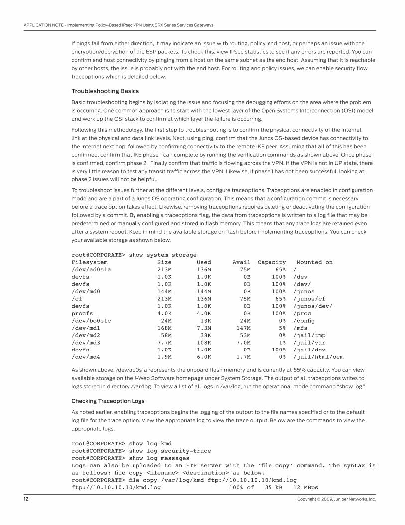
To troubleshoot issues further at the different levels, configure traceoptions. Traceoptions are enabled in configuration
mode and are a part of a Junos OS operating configuration. This means that a configuration commit is necessary
before a trace option takes effect. Likewise, removing traceoptions requires deleting or deactivating the configuration
followed by a commit. By enabling a traceoptions flag, the data from traceoptions is written to a log file that may be
predetermined or manually configured and stored in flash memory. This means that any trace logs are retained even
after a system reboot. Keep in mind the available storage on flash before implementing traceoptions. You can check
your available storage as shown below.
root@CORPORATE> show system storage Filesystem Size Used Avail Capacity Mounted on/dev/ad0s1a 213M 136M 75M 65% /devfs 1.0K 1.0K 0B 100% /devdevfs 1.0K 1.0K 0B 100% /dev//dev/md0 144M 144M 0B 100% /junos/cf 213M 136M 75M 65% /junos/cfdevfs 1.0K 1.0K 0B 100% /junos/dev/procfs 4.0K 4.0K 0B 100% /proc/dev/bo0s1e 24M 13K 24M 0% /config/dev/md1 168M 7.3M 147M 5% /mfs/dev/md2 58M 38K 53M 0% /jail/tmp/dev/md3 7.7M 108K 7.0M 1% /jail/vardevfs 1.0K 1.0K 0B 100% /jail/dev/dev/md4 1.9M 6.0K 1.7M 0% /jail/html/oem
As shown above, /dev/ad0s1a represents the onboard flash memory and is currently at 65% capacity. You can view
available storage on the J-Web Software homepage under System Storage. The output of all traceoptions writes to
logs stored in directory /var/log. To view a list of all logs in /var/log, run the operational mode command “show log.”
Checking Traceoption Logs
As noted earlier, enabling traceoptions begins the logging of the output to the file names specified or to the default
log file for the trace option. View the appropriate log to view the trace output. Below are the commands to view the
appropriate logs.
root@CORPORATE> show log kmdroot@CORPORATE> show log security-traceroot@CORPORATE> show log messagesLogs can also be uploaded to an FTP server with the ‘file copy’ command. The syntax is as follows: file copy <filename> <destination> as below.root@CORPORATE> file copy /var/log/kmd ftp://10.10.10.10/kmd.log ftp://10.10.10.10/kmd.log 100% of 35 kB 12 MBps

Copyright © 2009, Juniper Networks, Inc. 13
APPLICATION NOTE - Implementing Policy-Based IPsec VPN Using SRX Series Services Gateways
Troubleshooting IKE and IPsec Issues
To view success or failure messages in IKE or IPsec, view the kmd log using the command “show log kmd.” Although the
kmd log gives a general reason for any failure, it may be necessary to obtain additional details. For this we can enable
IKE traceoptions. Note that as a general rule, it is always best to troubleshoot on the peer that has the role of responder.
Enable IKE Traceoptions for Phase 1 and Phase 2 Negotiation Issues
Below is an example of all IKE traceoptions.
root@CORPORATE> configure Entering configuration mode
[edit]root@CORPORATE# edit security ike traceoptions
[edit security ike traceoptions]root@CORPORATE# set file ?Possible completions: <filename> Name of file in which to write trace information files Maximum number of trace files (2..1000) match Regular expression for lines to be logged no-world-readable Don’t allow any user to read the log file size Maximum trace file size (10240..1073741824) world-readable Allow any user to read the log file
[edit security ike traceoptions]root@CORPORATE# set flag ?Possible completions: all Trace everything certificates Trace certificate events database Trace security associations database events general Trace general events ike Trace IKE module processing parse Trace configuration processing policy-manager Trace policy manager processing routing-socket Trace routing socket messages timer Trace internal timer events
If no file name is specified, all IKE traceoptions write to the kmd log by default. If desired, you can specify a different
file name. To write trace data to the log, you must specify at least one flag option. Option “file size” determines the
maximum size of a log file in bytes. For example, 1m or 1000000 generates a maximum file size of 1 MB. Option “file files”
determines the maximum number of log files that are generated and stored in flash. Remember to commit the changes
to start the trace. Below is an example of recommended traceoptions for troubleshooting most IKE related issues.
[edit]root@CORPORATE# edit security ike traceoptions
[edit security ike traceoptions]root@CORPORATE# set file size 1mroot@CORPORATE# set flag policy-managerroot@CORPORATE# set flag ikeroot@CORPORATE# set flag routing-socketroot@CORPORATE# commit
Review Kmd Log for Success/Failure Messages
Below are some excerpts of successful phase 1 and phase 2 completions and some failure instances from “show log kmd.”

14 Copyright © 2009, Juniper Networks, Inc.
APPLICATION NOTE - Implementing Policy-Based IPsec VPN Using SRX Series Services Gateways
Phase 1 and Phase 2 Successful
Oct 8 10:41:40 Phase-1 [responder] done for local=ipv4(udp:500,[0..3]=1.1.1.2) remote=ipv4(udp:500,[0..3]=2.2.2.2)
Oct 8 10:41:51 Phase-2 [responder] done for p1_local=ipv4(udp:500,[0..3]=1.1.1.2) p1_remote=ipv4(udp:500,[0..3]=2.2.2.2) p2_local=ipv4_subnet(any:0,[0..7]=10.10.10.0/24) p2_remote=ipv4_subnet(any:0,[0..7]=192.168.168.0/24)
As shown above, the local address is 1.1.1.2 and the remote peer is 2.2.2.2. The output “udp:500“ indicates that no nat-
traversal was negotiated. You should see a phase 1 done message along with the role (initiator or responder). A phase
2 “done” message with proxy ID information is shown. Confirm that the IPsec SA is complete using the verification
commands mentioned previously.
Phase 1 Failing to Complete (Example 1)
Oct 8 10:31:10 Phase-1 [responder] failed with error(No proposal chosen) for local=unknown(any:0,[0..0]=) remote=ipv4(any:0,[0..3]=2.2.2.2)
Oct 8 10:31:10 1.1.1.2:500 (Responder) <-> 2.2.2.2:500 { 011359c9 ddef501d - 2216ed2a bfc50f5f [-1] / 0x00000000 } IP; Error = No proposal chosen (14)
As shown above, the local address is 1.1.1.2 and the remote peer is 2.2.2.2. The role is responder. The reason for failing
is due to “No proposal chosen.” This is likely due to mismatched phase 1 proposals. To resolve this issue, confirm that
phase 1 proposals match on both peers. Confirm that a tunnel policy exists for the VPN.
Phase 1 Failing to Complete (Example 2)
Oct 8 10:39:40 Unable to find phase-1 policy as remote peer:2.2.2.2 is not recognized.
Oct 8 10:39:40 KMD_PM_P1_POLICY_LOOKUP_FAILURE: Policy lookup for Phase-1 [responder] failed for p1_local=ipv4(any:0,[0..3]=1.1.1.2) p1_remote=ipv4(any:0,[0..3]=2.2.2.2)
Oct 8 10:39:40 1.1.1.2:500 (Responder) <-> 2.2.2.2:500 { 18983055 dbe1d0af - a4d6d829 f9ed3bba [-1] / 0x00000000 } IP; Error = No proposal chosen (14)
As shown above, the local address is 1.1.1.2 and the remote peer is 2.2.2.2. The role is responder. The reason for failing
may seem to indicate that no proposal was chosen, but in this case a message peer 2.2.2.2 has not been recognized.
Peer not recognized could be an incorrect peer address, mismatched peer ID type, or incorrect peer ID depending on
whether this is a dynamic or static VPN. This must be checked before the phase 1 proposal is checked. To resolve this
issue, confirm that the local peer has the correct peer IP address. Confirm that the peer is configured with IKE ID type
as IP address.
Phase 1 Failing to Complete (Example 3)
Oct 8 10:36:20 1.1.1.2:500 (Responder) <-> 2.2.2.2:500 { e9211eb9 b59d543c - 766a826d bd1d5ca1 [-1] / 0x00000000 } IP; Invalid next payload type = 17
Oct 8 10:36:20 Phase-1 [responder] failed with error(Invalid payload type) for local=unknown(any:0,[0..0]=) remote=ipv4(any:0,[0..3]=2.2.2.2)
As shown above, the remote peer is 2.2.2.2. Invalid payload type usually indicates that there has been a problem with
the decryption of the IKE packet due to a mismatched pre-shared key. To resolve this issue, confirm that pre-shared
keys match on both peers.
Copyright © 2009, Juniper Networks, Inc. 15
APPLICATION NOTE - Implementing Policy-Based IPsec VPN Using SRX Series Services Gateways
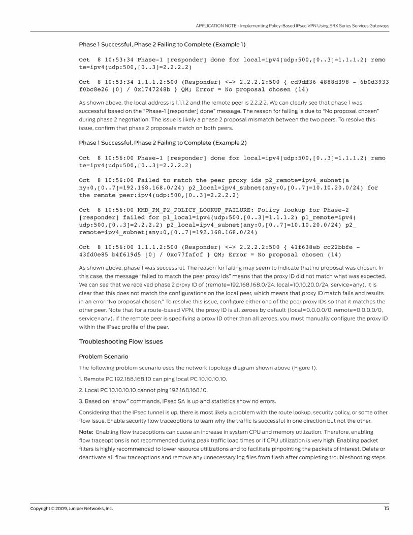
Phase 1 Successful, Phase 2 Failing to Complete (Example 1)
Oct 8 10:53:34 Phase-1 [responder] done for local=ipv4(udp:500,[0..3]=1.1.1.2) remote=ipv4(udp:500,[0..3]=2.2.2.2)
Oct 8 10:53:34 1.1.1.2:500 (Responder) <-> 2.2.2.2:500 { cd9dff36 4888d398 - 6b0d3933 f0bc8e26 [0] / 0x1747248b } QM; Error = No proposal chosen (14)
As shown above, the local address is 1.1.1.2 and the remote peer is 2.2.2.2. We can clearly see that phase 1 was
successful based on the “Phase-1 [responder] done” message. The reason for failing is due to “No proposal chosen”
during phase 2 negotiation. The issue is likely a phase 2 proposal mismatch between the two peers. To resolve this
issue, confirm that phase 2 proposals match on both peers.
Phase 1 Successful, Phase 2 Failing to Complete (Example 2)
Oct 8 10:56:00 Phase-1 [responder] done for local=ipv4(udp:500,[0..3]=1.1.1.2) remote=ipv4(udp:500,[0..3]=2.2.2.2)
Oct 8 10:56:00 Failed to match the peer proxy ids p2_remote=ipv4_subnet(any:0,[0..7]=192.168.168.0/24) p2_local=ipv4_subnet(any:0,[0..7]=10.10.20.0/24) for the remote peer:ipv4(udp:500,[0..3]=2.2.2.2)
Oct 8 10:56:00 KMD_PM_P2_POLICY_LOOKUP_FAILURE: Policy lookup for Phase-2 [responder] failed for p1_local=ipv4(udp:500,[0..3]=1.1.1.2) p1_remote=ipv4(udp:500,[0..3]=2.2.2.2) p2_local=ipv4_subnet(any:0,[0..7]=10.10.20.0/24) p2_remote=ipv4_subnet(any:0,[0..7]=192.168.168.0/24)
Oct 8 10:56:00 1.1.1.2:500 (Responder) <-> 2.2.2.2:500 { 41f638eb cc22bbfe - 43fd0e85 b4f619d5 [0] / 0xc77fafcf } QM; Error = No proposal chosen (14)
As shown above, phase 1 was successful. The reason for failing may seem to indicate that no proposal was chosen. In
this case, the message “failed to match the peer proxy ids” means that the proxy ID did not match what was expected.
We can see that we received phase 2 proxy ID of (remote=192.168.168.0/24, local=10.10.20.0/24, service=any). It is
clear that this does not match the configurations on the local peer, which means that proxy ID match fails and results
in an error “No proposal chosen.” To resolve this issue, configure either one of the peer proxy IDs so that it matches the
other peer. Note that for a route-based VPN, the proxy ID is all zeroes by default (local=0.0.0.0/0, remote=0.0.0.0/0,
service=any). If the remote peer is specifying a proxy ID other than all zeroes, you must manually configure the proxy ID
within the IPsec profile of the peer.
Troubleshooting Flow Issues
Problem Scenario
The following problem scenario uses the network topology diagram shown above (Figure 1).
1. Remote PC 192.168.168.10 can ping local PC 10.10.10.10.
2. Local PC 10.10.10.10 cannot ping 192.168.168.10.
3. Based on “show” commands, IPsec SA is up and statistics show no errors.
Considering that the IPsec tunnel is up, there is most likely a problem with the route lookup, security policy, or some other
flow issue. Enable security flow traceoptions to learn why the traffic is successful in one direction but not the other.
Note: Enabling flow traceoptions can cause an increase in system CPU and memory utilization. Therefore, enabling
flow traceoptions is not recommended during peak traffic load times or if CPU utilization is very high. Enabling packet
filters is highly recommended to lower resource utilizations and to facilitate pinpointing the packets of interest. Delete or
deactivate all flow traceoptions and remove any unnecessary log files from flash after completing troubleshooting steps.

16 Copyright © 2009, Juniper Networks, Inc.
APPLICATION NOTE - Implementing Policy-Based IPsec VPN Using SRX Series Services Gateways
Enabling Security Flow Traceoptions for Routing or Policy Issues
See the example of flow traceoptions below.
[edit]root@CORPORATE# edit security flow traceoptions
[edit security flow traceoptions]root@CORPORATE# set file ?Possible completions: <filename> Name of file in which to write trace information files Maximum number of trace files (2..1000) match Regular expression for lines to be logged no-world-readable Don’t allow any user to read the log file size Maximum trace file size (10240..1073741824) world-readable Allow any user to read the log file
[edit security flow traceoptions]root@CORPORATE# set flag ? Possible completions: ager Ager events all All events basic-datapath Basic packet flow cli CLI configuration and commands changes errors Flow errors fragmentation Ip fragmentation and reassembly events high-availability Flow high-availability information host-traffic Flow host-traffic information lookup Flow lookup events multicast Multicast flow information packet-drops Packet drops route Route information session Session creation and deletion events session-scan Session scan information tcp-advanced Advanced TCP packet flow tcp-basic TCP packet flow tunnel Tunnel information
By default, if a file name is not specified, all flow traceoptions output writes to the security trace log. If desired, specify
a different file name. To write trace data to the log, specify at least one flag option. Option “file size” determines the
maximum size of a log file in bytes. For example, 1m or 1000000 generates a maximum file size of 1 MB. Option “file
files” determines the maximum number of log files that are generated and stored in flash. Remember to commit the
changes to start the trace.
In addition to the above, Junos OS has the ability to configure packet filters to limit the scope of the traffic to be
captured. You can filter the output based on source/destination IP, source/destination port, interface, and IP protocol.
Up to 64 filters can be configured. A packet filter matches the reverse direction to capture the reply traffic, assuming
the source of the original packet matches the filter. See the example of flow packet filter options below.
[edit security flow traceoptions]root@CORPORATE# set packet-filter <filter-name> ?Possible completions:+ apply-groups Groups from which to inherit configuration data+ apply-groups-except Don’t inherit configuration data from these groups destination-port Match TCP/UDP destination port destination-prefix Destination IPv4 address prefix interface Logical interface protocol Match IP protocol type source-port Match TCP/UDP source port source-prefix Source IPv4 address prefix
Copyright © 2009, Juniper Networks, Inc. 17
APPLICATION NOTE - Implementing Policy-Based IPsec VPN Using SRX Series Services Gateways
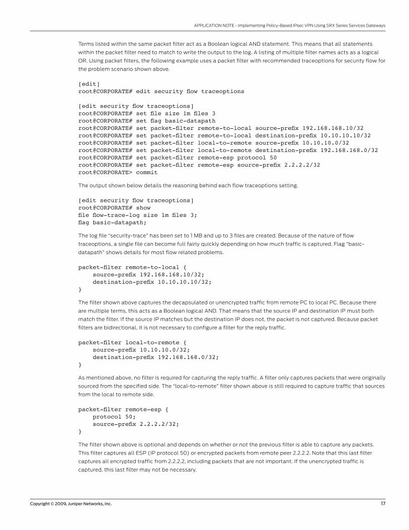
Terms listed within the same packet filter act as a Boolean logical AND statement. This means that all statements
within the packet filter need to match to write the output to the log. A listing of multiple filter names acts as a logical
OR. Using packet filters, the following example uses a packet filter with recommended traceoptions for security flow for
the problem scenario shown above.
[edit]root@CORPORATE# edit security flow traceoptions
[edit security flow traceoptions]root@CORPORATE# set file size 1m files 3root@CORPORATE# set flag basic-datapathroot@CORPORATE# set packet-filter remote-to-local source-prefix 192.168.168.10/32root@CORPORATE# set packet-filter remote-to-local destination-prefix 10.10.10.10/32root@CORPORATE# set packet-filter local-to-remote source-prefix 10.10.10.0/32root@CORPORATE# set packet-filter local-to-remote destination-prefix 192.168.168.0/32root@CORPORATE# set packet-filter remote-esp protocol 50root@CORPORATE# set packet-filter remote-esp source-prefix 2.2.2.2/32root@CORPORATE> commit
The output shown below details the reasoning behind each flow traceoptions setting.
[edit security flow traceoptions]root@CORPORATE# show file flow-trace-log size 1m files 3;flag basic-datapath;
The log file “security-trace” has been set to 1 MB and up to 3 files are created. Because of the nature of flow
traceoptions, a single file can become full fairly quickly depending on how much traffic is captured. Flag “basic-
datapath” shows details for most flow related problems.
packet-filter remote-to-local { source-prefix 192.168.168.10/32; destination-prefix 10.10.10.10/32;}
The filter shown above captures the decapsulated or unencrypted traffic from remote PC to local PC. Because there
are multiple terms, this acts as a Boolean logical AND. That means that the source IP and destination IP must both
match the filter. If the source IP matches but the destination IP does not, the packet is not captured. Because packet
filters are bidirectional, it is not necessary to configure a filter for the reply traffic.
packet-filter local-to-remote { source-prefix 10.10.10.0/32; destination-prefix 192.168.168.0/32;}
As mentioned above, no filter is required for capturing the reply traffic. A filter only captures packets that were originally
sourced from the specified side. The “local-to-remote” filter shown above is still required to capture traffic that sources
from the local to remote side.
packet-filter remote-esp { protocol 50; source-prefix 2.2.2.2/32;}
The filter shown above is optional and depends on whether or not the previous filter is able to capture any packets.
This filter captures all ESP (IP protocol 50) or encrypted packets from remote peer 2.2.2.2. Note that this last filter
captures all encrypted traffic from 2.2.2.2, including packets that are not important. If the unencrypted traffic is
captured, this last filter may not be necessary.

18 Copyright © 2009, Juniper Networks, Inc.
APPLICATION NOTE - Implementing Policy-Based IPsec VPN Using SRX Series Services Gateways
Using the three problem statements mentioned in the problem scenario, use the flow traceoptions log to isolate the
issue. We can assume that the third statement is correct based on IKE and IPsec troubleshooting. Validate the first
problem statement to confirm that the remote PC can ping the local PC. Next, troubleshoot the second problem
statement to find out why the traffic fails in the reverse direction.
Validating First Problem Statement
Begin by sourcing a ping from 192.168.168.10 to 10.10.10.10. View the security trace log. Because a file name was not
specified, view flow traceoptions output with the command “show log security-trace.” Below is the flow traceoptions
output showing the successful traffic flow from remote PC to local PC. The first packet captured is the ESP or
encrypted packet as shown below.
******<2.2.2.2/42558->1.1.1.2/45679;50> matched filter remote-esp: <untrust/ge-0/0/3.0> ******Oct 6 19:20:33 19:20:33.863580:CID-0:RT: packet [184] ipid = 12384, @497afcee ****** Oct 6 19:20:33 19:20:33.863590:CID-0:RT: ge-0/0/3.0:2.2.2.2->1.1.1.2, 50 Oct 6 19:20:33 19:20:33.863597:CID-0:RT: find flow: table 0x4b5265e0, hash 192852(0x3ffff), sa 2.2.2.2, da 1.1.1.2, sp 42558, dp 45679, proto 50, tok 12 Oct 6 19:20:33 19:20:33.863614:CID-0:RT: find flow: table 0x4b59eb00, hash 340(0xfff), sa 2.2.2.2, da 1.1.1.2, sp 42558, dp 45679, proto 50, tok 12 Oct 6 19:20:33 19:20:33.863630:CID-0:RT: flow session id 257024 Oct 6 19:20:33 19:20:33.863635:CID-0:RT: flow_decrypt: tun 51761360(flag b), iif 68 Oct 6 19:20:33 19:20:33.863682:CID-0:RT:inject tunnel pkt mbuf 0x497afb40 Oct 6 19:20:33 19:20:33.863689:CID-0:RT:injected tunnel pkt mbuf 0x497afb40
Based on the top header, the packet is from 2.2.2.2 to 1.1.1.2, IP protocol 50. The ingress interface is ge-0/0/3.0 in zone
“untrust” with matching packet-filter “remote-esp.” This is the ESP packet from the remote peer. The port values for
IP protocol 50 are not the same as with TCP/UDP. The values are an amalgamation of the SPI value for the tunnel.
The “flow session id” is the tunnel session created for the ESP traffic. You can view details about this session with the
command “show security flow session session-identifier <session id>.” The “flow_decrypt” message indicates that
the decryption process is to take place. The “tun” value is an internal pointer and “iif” refers to the incoming logical
interface index. You can view all logical interface index numbers with the command “show interface extensive.”
Below is the decrypted packet output.
******<192.168.168.10/2048->10.10.10.10/1098;1> matched filter remote-to-local: <untrust/ge-0/0/3.0> ******Oct 6 19:20:33 19:20:33.863714:CID-0:RT: packet [128] ipid = 41035, @497afd12 ****** Oct 6 19:20:33 19:20:33.863724:CID-0:RT: ge-0/0/3.0:192.168.168.10->10.10.10.10, icmp, (8/0) Oct 6 19:20:33 19:20:33.863730:CID-0:RT: find flow: table 0x4b5265e0, hash 223505(0x3ffff), sa 192.168.168.10, da 10.10.10.10, sp 21480, dp 1024, proto 1, tok 12 Oct 6 19:20:33 19:20:33.863746:CID-0:RT: flow_first_sanity_check: in <ge-0/0/3.0>, out <N/A> Oct 6 19:20:33 19:20:33.863754:CID-0:RT: flow_first_in_dst_nat: in <ge-0/0/3.0>, out
Copyright © 2009, Juniper Networks, Inc. 19
APPLICATION NOTE - Implementing Policy-Based IPsec VPN Using SRX Series Services Gateways
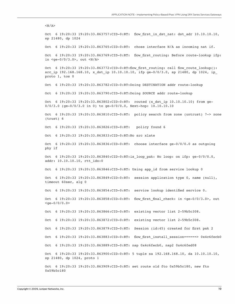
<N/A> Oct 6 19:20:33 19:20:33.863757:CID-0:RT: flow_first_in_dst_nat: dst_adr 10.10.10.10, sp 21480, dp 1024 Oct 6 19:20:33 19:20:33.863765:CID-0:RT: chose interface N/A as incoming nat if. Oct 6 19:20:33 19:20:33.863769:CID-0:RT: flow_first_routing: Before route-lookup ifp: in <ge-0/0/3.0>, out <N/A> Oct 6 19:20:33 19:20:33.863772:CID-0:RT:flow_first_routing: call flow_route_lookup(): src_ip 192.168.168.10, x_dst_ip 10.10.10.10, ifp ge-0/0/3.0, sp 21480, dp 1024, ip_proto 1, tos 0 Oct 6 19:20:33 19:20:33.863782:CID-0:RT:Doing DESTINATION addr route-lookup Oct 6 19:20:33 19:20:33.863790:CID-0:RT:Doing SOURCE addr route-lookup Oct 6 19:20:33 19:20:33.863802:CID-0:RT: routed (x_dst_ip 10.10.10.10) from ge-0/0/3.0 (ge-0/0/3.0 in 0) to ge-0/0/0.0, Next-hop: 10.10.10.10 Oct 6 19:20:33 19:20:33.863810:CID-0:RT: policy search from zone (untrust) 7-> zone (trust) 6 Oct 6 19:20:33 19:20:33.863826:CID-0:RT: policy found 6 Oct 6 19:20:33 19:20:33.863833:CID-0:RT:No src xlate Oct 6 19:20:33 19:20:33.863836:CID-0:RT: choose interface ge-0/0/0.0 as outgoing phy if Oct 6 19:20:33 19:20:33.863840:CID-0:RT:is_loop_pak: No loop: on ifp: ge-0/0/0.0, addr: 10.10.10.10, rtt_idx:0 Oct 6 19:20:33 19:20:33.863846:CID-0:RT: Using app_id from service lookup 0 Oct 6 19:20:33 19:20:33.863849:CID-0:RT: session application type 0, name (null), timeout 60sec, alg 0 Oct 6 19:20:33 19:20:33.863854:CID-0:RT: service lookup identified service 0. Oct 6 19:20:33 19:20:33.863858:CID-0:RT: flow_first_final_check: in <ge-0/0/3.0>, out <ge-0/0/0.0> Oct 6 19:20:33 19:20:33.863866:CID-0:RT: existing vector list 2-59b5c308. Oct 6 19:20:33 19:20:33.863872:CID-0:RT: existing vector list 2-59b5c308. Oct 6 19:20:33 19:20:33.863879:CID-0:RT: Session (id:45) created for first pak 2 Oct 6 19:20:33 19:20:33.863883:CID-0:RT: flow_first_install_session======> 0x4c6fecb0 Oct 6 19:20:33 19:20:33.863889:CID-0:RT: nsp 0x4c6fecb0, nsp2 0x4c6fed08 Oct 6 19:20:33 19:20:33.863900:CID-0:RT: 5 tuple sa 192.168.168.10, da 10.10.10.10, sp 21480, dp 1024, proto 1 Oct 6 19:20:33 19:20:33.863909:CID-0:RT: set route old fto 0x59b5c180, new fto 0x59b5c180
20 Copyright © 2009, Juniper Networks, Inc.
APPLICATION NOTE - Implementing Policy-Based IPsec VPN Using SRX Series Services Gateways
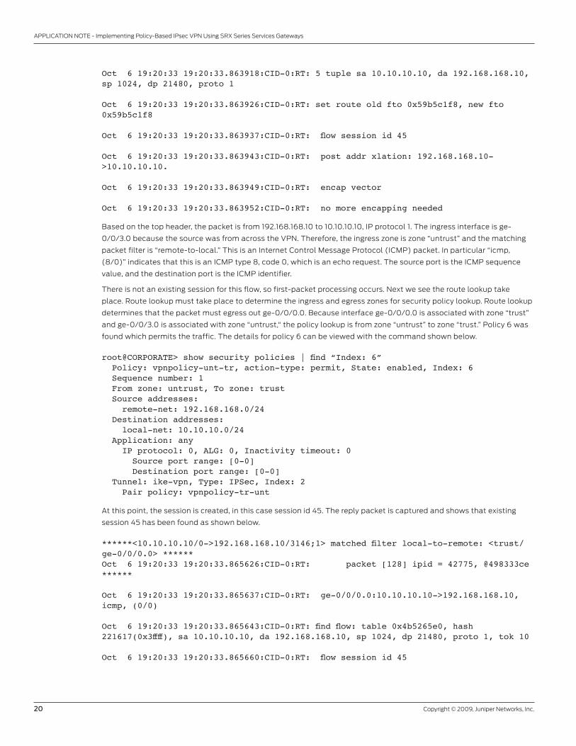
Oct 6 19:20:33 19:20:33.863918:CID-0:RT: 5 tuple sa 10.10.10.10, da 192.168.168.10, sp 1024, dp 21480, proto 1 Oct 6 19:20:33 19:20:33.863926:CID-0:RT: set route old fto 0x59b5c1f8, new fto 0x59b5c1f8 Oct 6 19:20:33 19:20:33.863937:CID-0:RT: flow session id 45 Oct 6 19:20:33 19:20:33.863943:CID-0:RT: post addr xlation: 192.168.168.10->10.10.10.10. Oct 6 19:20:33 19:20:33.863949:CID-0:RT: encap vector Oct 6 19:20:33 19:20:33.863952:CID-0:RT: no more encapping needed
Based on the top header, the packet is from 192.168.168.10 to 10.10.10.10, IP protocol 1. The ingress interface is ge-
0/0/3.0 because the source was from across the VPN. Therefore, the ingress zone is zone “untrust” and the matching
packet filter is “remote-to-local.” This is an Internet Control Message Protocol (ICMP) packet. In particular “icmp,
(8/0)” indicates that this is an ICMP type 8, code 0, which is an echo request. The source port is the ICMP sequence
value, and the destination port is the ICMP identifier.
There is not an existing session for this flow, so first-packet processing occurs. Next we see the route lookup take
place. Route lookup must take place to determine the ingress and egress zones for security policy lookup. Route lookup
determines that the packet must egress out ge-0/0/0.0. Because interface ge-0/0/0.0 is associated with zone “trust”
and ge-0/0/3.0 is associated with zone “untrust,“ the policy lookup is from zone “untrust” to zone “trust.” Policy 6 was
found which permits the traffic. The details for policy 6 can be viewed with the command shown below.
root@CORPORATE> show security policies | find “Index: 6” Policy: vpnpolicy-unt-tr, action-type: permit, State: enabled, Index: 6 Sequence number: 1 From zone: untrust, To zone: trust Source addresses: remote-net: 192.168.168.0/24 Destination addresses: local-net: 10.10.10.0/24 Application: any IP protocol: 0, ALG: 0, Inactivity timeout: 0 Source port range: [0-0] Destination port range: [0-0] Tunnel: ike-vpn, Type: IPSec, Index: 2 Pair policy: vpnpolicy-tr-unt
At this point, the session is created, in this case session id 45. The reply packet is captured and shows that existing
session 45 has been found as shown below.
******<10.10.10.10/0->192.168.168.10/3146;1> matched filter local-to-remote: <trust/ge-0/0/0.0> ******Oct 6 19:20:33 19:20:33.865626:CID-0:RT: packet [128] ipid = 42775, @498333ce ****** Oct 6 19:20:33 19:20:33.865637:CID-0:RT: ge-0/0/0.0:10.10.10.10->192.168.168.10, icmp, (0/0) Oct 6 19:20:33 19:20:33.865643:CID-0:RT: find flow: table 0x4b5265e0, hash 221617(0x3ffff), sa 10.10.10.10, da 192.168.168.10, sp 1024, dp 21480, proto 1, tok 10 Oct 6 19:20:33 19:20:33.865660:CID-0:RT: flow session id 45
Copyright © 2009, Juniper Networks, Inc. 21
APPLICATION NOTE - Implementing Policy-Based IPsec VPN Using SRX Series Services Gateways
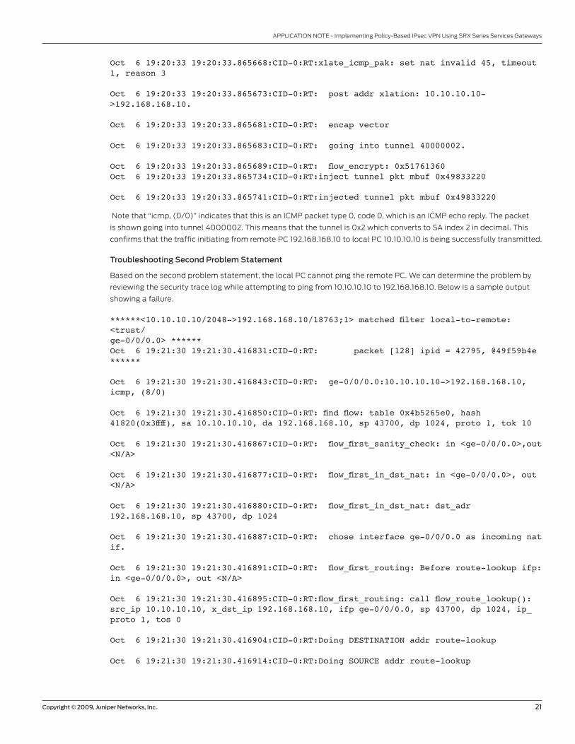
Oct 6 19:20:33 19:20:33.865668:CID-0:RT:xlate_icmp_pak: set nat invalid 45, timeout 1, reason 3 Oct 6 19:20:33 19:20:33.865673:CID-0:RT: post addr xlation: 10.10.10.10->192.168.168.10. Oct 6 19:20:33 19:20:33.865681:CID-0:RT: encap vector Oct 6 19:20:33 19:20:33.865683:CID-0:RT: going into tunnel 40000002. Oct 6 19:20:33 19:20:33.865689:CID-0:RT: flow_encrypt: 0x51761360Oct 6 19:20:33 19:20:33.865734:CID-0:RT:inject tunnel pkt mbuf 0x49833220 Oct 6 19:20:33 19:20:33.865741:CID-0:RT:injected tunnel pkt mbuf 0x49833220
Note that “icmp, (0/0)” indicates that this is an ICMP packet type 0, code 0, which is an ICMP echo reply. The packet
is shown going into tunnel 4000002. This means that the tunnel is 0x2 which converts to SA index 2 in decimal. This
confirms that the traffic initiating from remote PC 192.168.168.10 to local PC 10.10.10.10 is being successfully transmitted.
Troubleshooting Second Problem Statement
Based on the second problem statement, the local PC cannot ping the remote PC. We can determine the problem by
reviewing the security trace log while attempting to ping from 10.10.10.10 to 192.168.168.10. Below is a sample output
showing a failure.
******<10.10.10.10/2048->192.168.168.10/18763;1> matched filter local-to-remote: <trust/ge-0/0/0.0> ******Oct 6 19:21:30 19:21:30.416831:CID-0:RT: packet [128] ipid = 42795, @49f59b4e ****** Oct 6 19:21:30 19:21:30.416843:CID-0:RT: ge-0/0/0.0:10.10.10.10->192.168.168.10, icmp, (8/0) Oct 6 19:21:30 19:21:30.416850:CID-0:RT: find flow: table 0x4b5265e0, hash 41820(0x3ffff), sa 10.10.10.10, da 192.168.168.10, sp 43700, dp 1024, proto 1, tok 10 Oct 6 19:21:30 19:21:30.416867:CID-0:RT: flow_first_sanity_check: in <ge-0/0/0.0>,out <N/A> Oct 6 19:21:30 19:21:30.416877:CID-0:RT: flow_first_in_dst_nat: in <ge-0/0/0.0>, out <N/A> Oct 6 19:21:30 19:21:30.416880:CID-0:RT: flow_first_in_dst_nat: dst_adr 192.168.168.10, sp 43700, dp 1024 Oct 6 19:21:30 19:21:30.416887:CID-0:RT: chose interface ge-0/0/0.0 as incoming nat if. Oct 6 19:21:30 19:21:30.416891:CID-0:RT: flow_first_routing: Before route-lookup ifp: in <ge-0/0/0.0>, out <N/A> Oct 6 19:21:30 19:21:30.416895:CID-0:RT:flow_first_routing: call flow_route_lookup(): src_ip 10.10.10.10, x_dst_ip 192.168.168.10, ifp ge-0/0/0.0, sp 43700, dp 1024, ip_proto 1, tos 0 Oct 6 19:21:30 19:21:30.416904:CID-0:RT:Doing DESTINATION addr route-lookup Oct 6 19:21:30 19:21:30.416914:CID-0:RT:Doing SOURCE addr route-lookup
22 Copyright © 2009, Juniper Networks, Inc.
APPLICATION NOTE - Implementing Policy-Based IPsec VPN Using SRX Series Services Gateways
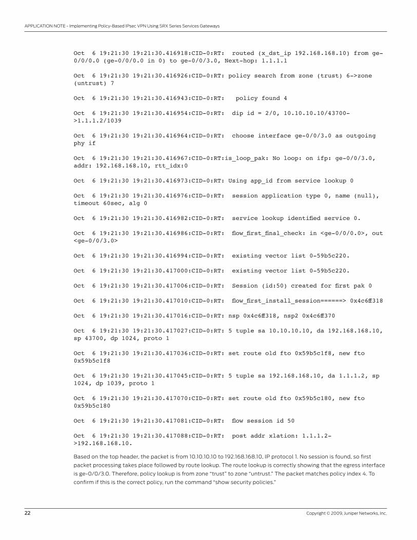
Oct 6 19:21:30 19:21:30.416918:CID-0:RT: routed (x_dst_ip 192.168.168.10) from ge-0/0/0.0 (ge-0/0/0.0 in 0) to ge-0/0/3.0, Next-hop: 1.1.1.1 Oct 6 19:21:30 19:21:30.416926:CID-0:RT: policy search from zone (trust) 6->zone (untrust) 7 Oct 6 19:21:30 19:21:30.416943:CID-0:RT: policy found 4 Oct 6 19:21:30 19:21:30.416954:CID-0:RT: dip id = 2/0, 10.10.10.10/43700->1.1.1.2/1039 Oct 6 19:21:30 19:21:30.416964:CID-0:RT: choose interface ge-0/0/3.0 as outgoing phy if Oct 6 19:21:30 19:21:30.416967:CID-0:RT:is_loop_pak: No loop: on ifp: ge-0/0/3.0, addr: 192.168.168.10, rtt_idx:0 Oct 6 19:21:30 19:21:30.416973:CID-0:RT: Using app_id from service lookup 0 Oct 6 19:21:30 19:21:30.416976:CID-0:RT: session application type 0, name (null), timeout 60sec, alg 0 Oct 6 19:21:30 19:21:30.416982:CID-0:RT: service lookup identified service 0. Oct 6 19:21:30 19:21:30.416986:CID-0:RT: flow_first_final_check: in <ge-0/0/0.0>, out <ge-0/0/3.0> Oct 6 19:21:30 19:21:30.416994:CID-0:RT: existing vector list 0-59b5c220. Oct 6 19:21:30 19:21:30.417000:CID-0:RT: existing vector list 0-59b5c220. Oct 6 19:21:30 19:21:30.417006:CID-0:RT: Session (id:50) created for first pak 0 Oct 6 19:21:30 19:21:30.417010:CID-0:RT: flow_first_install_session======> 0x4c6ff318 Oct 6 19:21:30 19:21:30.417016:CID-0:RT: nsp 0x4c6ff318, nsp2 0x4c6ff370 Oct 6 19:21:30 19:21:30.417027:CID-0:RT: 5 tuple sa 10.10.10.10, da 192.168.168.10, sp 43700, dp 1024, proto 1 Oct 6 19:21:30 19:21:30.417036:CID-0:RT: set route old fto 0x59b5c1f8, new fto 0x59b5c1f8 Oct 6 19:21:30 19:21:30.417045:CID-0:RT: 5 tuple sa 192.168.168.10, da 1.1.1.2, sp 1024, dp 1039, proto 1 Oct 6 19:21:30 19:21:30.417070:CID-0:RT: set route old fto 0x59b5c180, new fto 0x59b5c180 Oct 6 19:21:30 19:21:30.417081:CID-0:RT: flow session id 50 Oct 6 19:21:30 19:21:30.417088:CID-0:RT: post addr xlation: 1.1.1.2->192.168.168.10.
Based on the top header, the packet is from 10.10.10.10 to 192.168.168.10, IP protocol 1. No session is found, so first
packet processing takes place followed by route lookup. The route lookup is correctly showing that the egress interface
is ge-0/0/3.0. Therefore, policy lookup is from zone “trust” to zone “untrust.” The packet matches policy index 4. To
confirm if this is the correct policy, run the command “show security policies.”
Copyright © 2009, Juniper Networks, Inc. 23
APPLICATION NOTE - Implementing Policy-Based IPsec VPN Using SRX Series Services Gateways
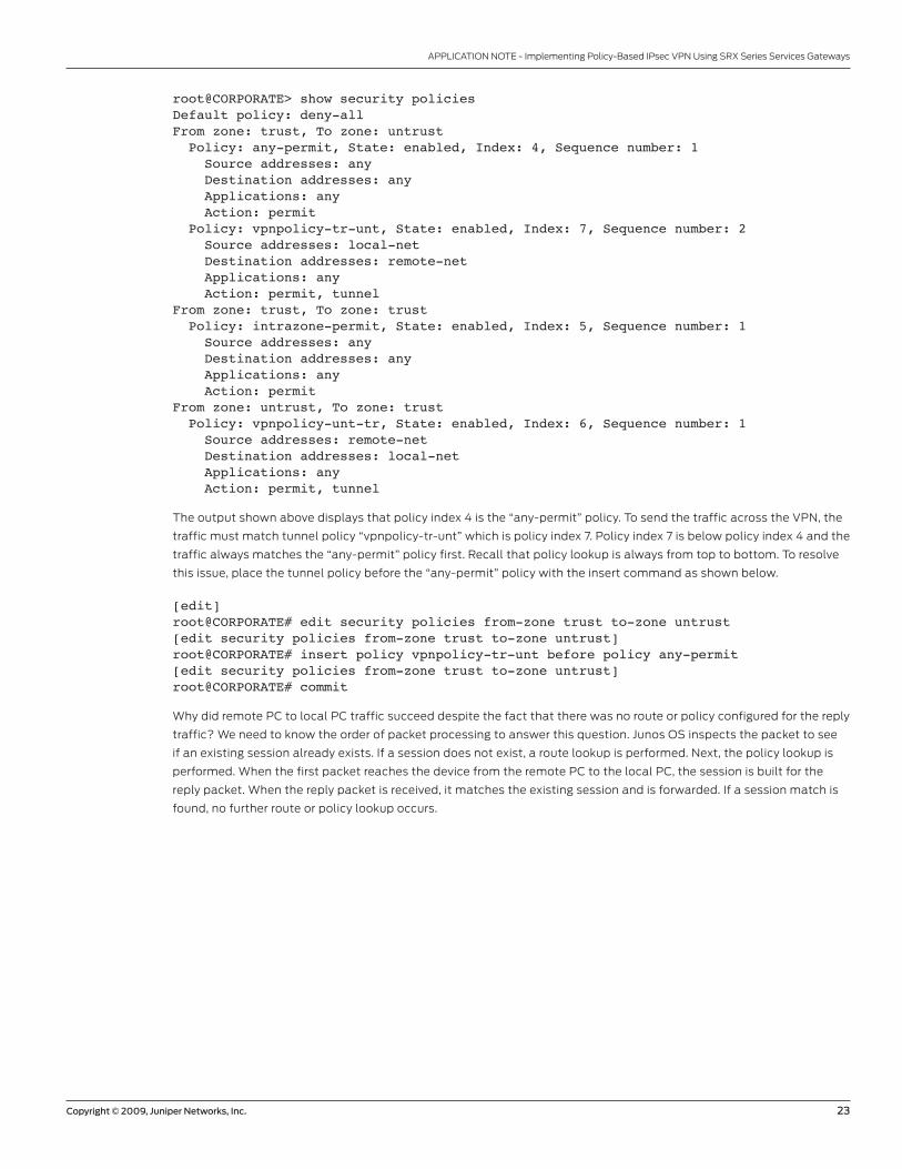
root@CORPORATE> show security policies Default policy: deny-allFrom zone: trust, To zone: untrust Policy: any-permit, State: enabled, Index: 4, Sequence number: 1 Source addresses: any Destination addresses: any Applications: any Action: permit Policy: vpnpolicy-tr-unt, State: enabled, Index: 7, Sequence number: 2 Source addresses: local-net Destination addresses: remote-net Applications: any Action: permit, tunnelFrom zone: trust, To zone: trust Policy: intrazone-permit, State: enabled, Index: 5, Sequence number: 1 Source addresses: any Destination addresses: any Applications: any Action: permitFrom zone: untrust, To zone: trust Policy: vpnpolicy-unt-tr, State: enabled, Index: 6, Sequence number: 1 Source addresses: remote-net Destination addresses: local-net Applications: any Action: permit, tunnel
The output shown above displays that policy index 4 is the “any-permit” policy. To send the traffic across the VPN, the
traffic must match tunnel policy “vpnpolicy-tr-unt” which is policy index 7. Policy index 7 is below policy index 4 and the
traffic always matches the “any-permit” policy first. Recall that policy lookup is always from top to bottom. To resolve
this issue, place the tunnel policy before the “any-permit” policy with the insert command as shown below.
[edit] root@CORPORATE# edit security policies from-zone trust to-zone untrust[edit security policies from-zone trust to-zone untrust]root@CORPORATE# insert policy vpnpolicy-tr-unt before policy any-permit[edit security policies from-zone trust to-zone untrust]root@CORPORATE# commit
Why did remote PC to local PC traffic succeed despite the fact that there was no route or policy configured for the reply
traffic? We need to know the order of packet processing to answer this question. Junos OS inspects the packet to see
if an existing session already exists. If a session does not exist, a route lookup is performed. Next, the policy lookup is
performed. When the first packet reaches the device from the remote PC to the local PC, the session is built for the
reply packet. When the reply packet is received, it matches the existing session and is forwarded. If a session match is
found, no further route or policy lookup occurs.
24 Copyright © 2009, Juniper Networks, Inc.
APPLICATION NOTE - Implementing Policy-Based IPsec VPN Using SRX Series Services Gateways
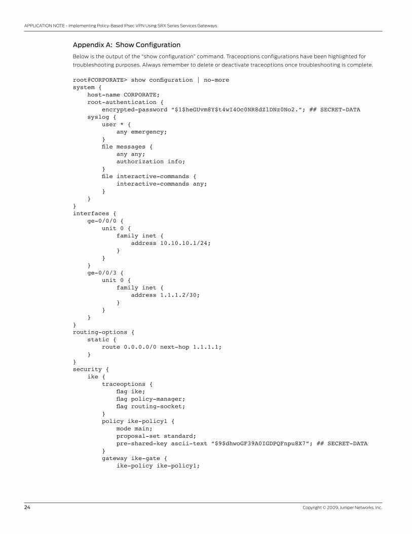
Appendix A: Show Configuration
Below is the output of the “show configuration” command. Traceoptions configurations have been highlighted for
troubleshooting purposes. Always remember to delete or deactivate traceoptions once troubleshooting is complete.
root@CORPORATE> show configuration | no-moresystem { host-name CORPORATE; root-authentication { encrypted-password “$1$heGUvm8Y$t4wI4Oc0NR8dZlDNz0No2.”; ## SECRET-DATA syslog { user * { any emergency; } file messages { any any; authorization info; } file interactive-commands { interactive-commands any; } }}interfaces { ge-0/0/0 { unit 0 { family inet { address 10.10.10.1/24; } } } ge-0/0/3 { unit 0 { family inet { address 1.1.1.2/30; } } }}routing-options { static { route 0.0.0.0/0 next-hop 1.1.1.1; }}security { ike { traceoptions { flag ike; flag policy-manager; flag routing-socket; } policy ike-policy1 { mode main; proposal-set standard; pre-shared-key ascii-text “$9$dhwoGF39A0IGDPQFnpu8X7”; ## SECRET-DATA } gateway ike-gate { ike-policy ike-policy1;
Copyright © 2009, Juniper Networks, Inc. 25
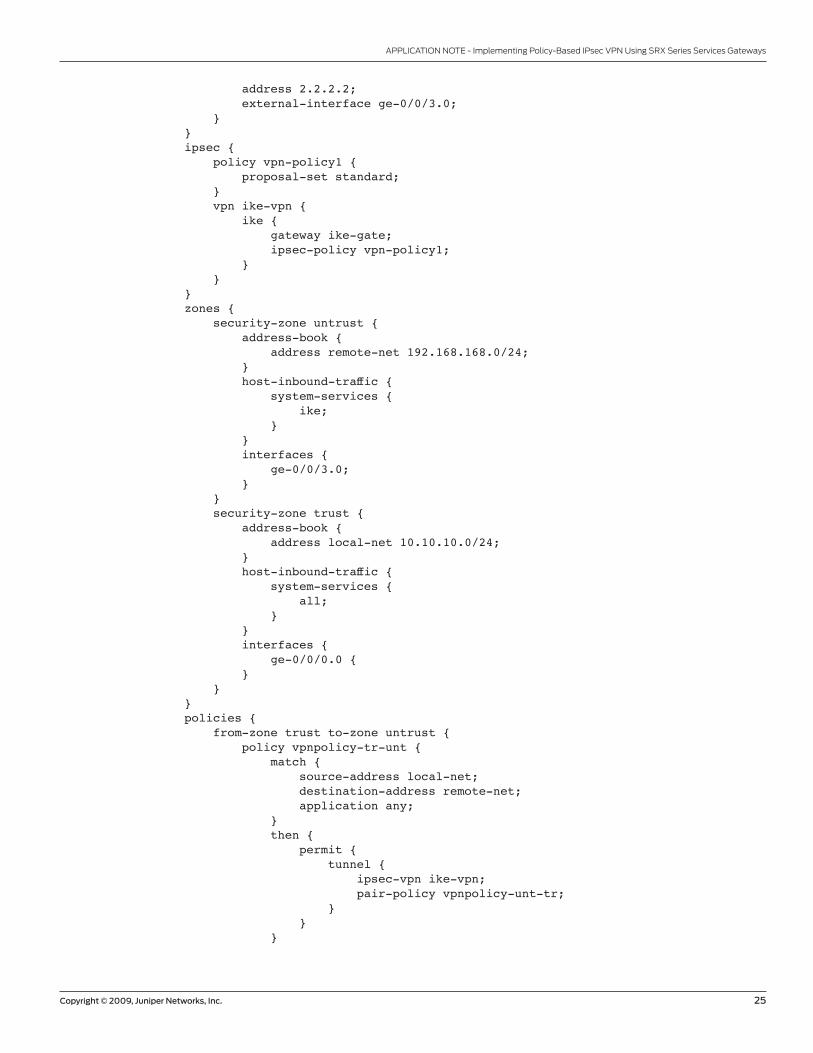
APPLICATION NOTE - Implementing Policy-Based IPsec VPN Using SRX Series Services Gateways
address 2.2.2.2; external-interface ge-0/0/3.0; } } ipsec { policy vpn-policy1 { proposal-set standard; } vpn ike-vpn { ike { gateway ike-gate; ipsec-policy vpn-policy1; } } } zones { security-zone untrust { address-book { address remote-net 192.168.168.0/24; } host-inbound-traffic { system-services { ike; } } interfaces { ge-0/0/3.0; } } security-zone trust { address-book { address local-net 10.10.10.0/24; } host-inbound-traffic { system-services { all; } } interfaces { ge-0/0/0.0 { } } } policies { from-zone trust to-zone untrust { policy vpnpolicy-tr-unt { match { source-address local-net; destination-address remote-net; application any; } then { permit { tunnel { ipsec-vpn ike-vpn; pair-policy vpnpolicy-unt-tr; } } }
26 Copyright © 2009, Juniper Networks, Inc.
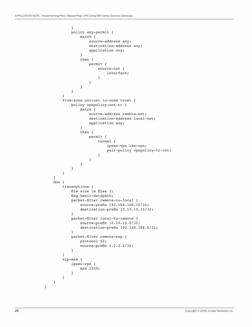
APPLICATION NOTE - Implementing Policy-Based IPsec VPN Using SRX Series Services Gateways
} policy any-permit { match { source-address any; destination-address any; application any; } then { permit { source-nat { interface; } } } } } from-zone untrust to-zone trust { policy vpnpolicy-unt-tr { match { source-address remote-net; destination-address local-net; application any; } then { permit { tunnel { ipsec-vpn ike-vpn; pair-policy vpnpolicy-tr-unt; } } } } } } flow { traceoptions { file size 1m files 3; flag basic-datapath; packet-filter remote-to-local { source-prefix 192.168.168.10/32; destination-prefix 10.10.10.10/32; } packet-filter local-to-remote { source-prefix 10.10.10.0/32; destination-prefix 192.168.168.0/32; } packet-filter remote-esp { protocol 50; source-prefix 2.2.2.2/32; } } tcp-mss { ipsec-vpn { mss 1350; } } }}
Copyright © 2009, Juniper Networks, Inc. 27
APPLICATION NOTE - Implementing Policy-Based IPsec VPN Using SRX Series Services Gateways
3500175-001-EN Oct 2009
Copyright 2009 Juniper Networks, Inc. All rights reserved. Juniper Networks, the Juniper Networks logo, Junos, NetScreen, and ScreenOS are registered trademarks of Juniper Networks, Inc. in the United States and other countries. All other trademarks, service marks, registered marks, or registered service marks are the property of their respective owners. Juniper Networks assumes no responsibility for any inaccuracies in this document. Juniper Networks reserves the right to change, modify, transfer, or otherwise revise this publication without notice.
EMEA Headquarters
Juniper Networks Ireland
Airside Business Park
Swords, County Dublin, Ireland
Phone: 35.31.8903.600
EMEA Sales: 00800.4586.4737
Fax: 35.31.8903.601
APAC Headquarters
Juniper Networks (Hong Kong)
26/F, Cityplaza One
1111 King’s Road
Taikoo Shing, Hong Kong
Phone: 852.2332.3636
Fax: 852.2574.7803
Corporate and Sales Headquarters
Juniper Networks, Inc.
1194 North Mathilda Avenue
Sunnyvale, CA 94089 USA
Phone: 888.JUNIPER (888.586.4737)
or 408.745.2000
Fax: 408.745.2100
www.juniper.net
To purchase Juniper Networks solutions,
please contact your Juniper Networks
representative at 1-866-298-6428 or
authorized reseller.
Printed on recycled paper
About Juniper Networks
Juniper Networks, Inc. is the leader in high-performance networking. Juniper offers a high-performance network
infrastructure that creates a responsive and trusted environment for accelerating the deployment of services and
applications over a single network. This fuels high-performance businesses. Additional information can be found at
www.juniper.net.
Top Related