


Languages
Pages
Legal

DIGITAL HOLOGRAPHY
AND
IMAGE PROCESSING

L. Yaroslavsky, Ph.D., Dr. Sc. Phys&Math,
ProfessorDept. of Interdisciplinary Studies, Faculty of Engineering, Tel Aviv
University, Tel Aviv, Israelwww.eng.tau.ac.il/~yaro

Digital holography and image processing: twins born by the computer era
Digital holography:- computer synthesis, analysis and simulation of wave fieldsDigital image processing:- digital image formation;
- image perfection;
- image enhancement for visual analysis;
- image measurements and parameter estimation;
- image storage; image visualization
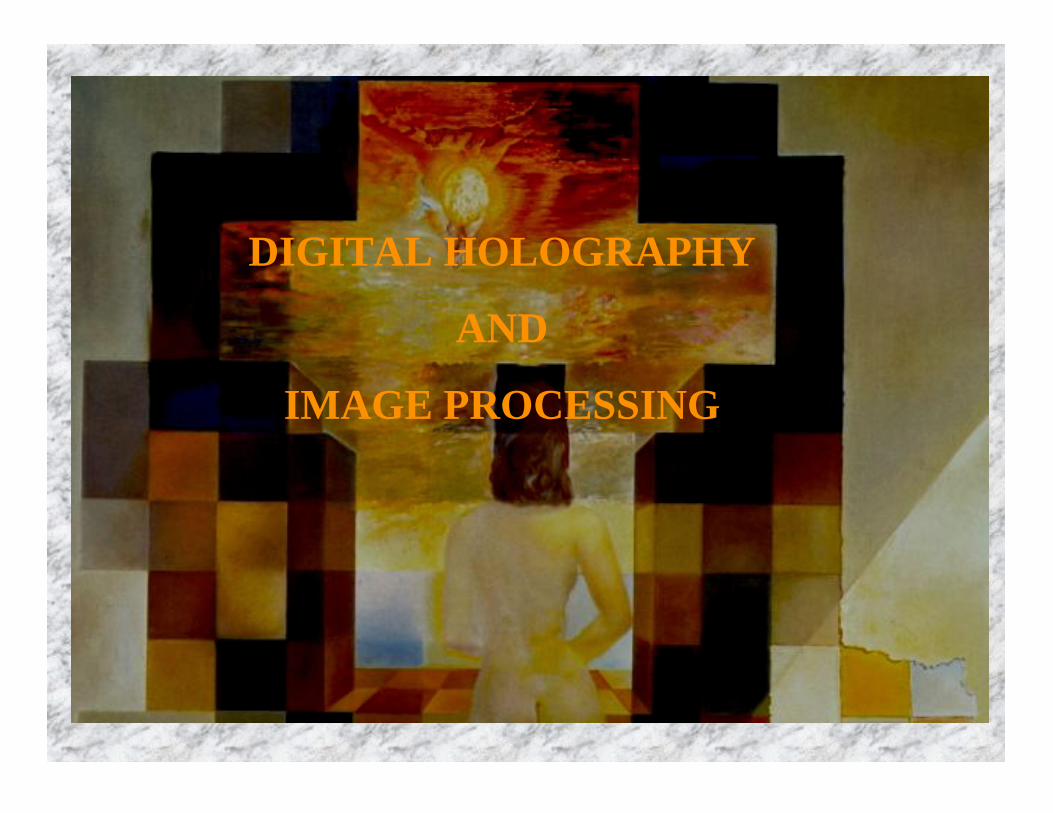
New qualities that are brought to optical information systems by digital computers and processors:
• Flexibility and adaptability. The most substantial advantage of digital computers as compared with analog electronic and optical information processing devices is that no hardware modifications are necessary to reprogram digital computers to solving different tasks. With the same hardware, one can build an arbitrary problem solver by simply selecting or designing an appropriate code for the computer. This feature makes digital computers also an ideal vehicle for processing optical signals adaptively since, with the help of computers, they can adapt rapidly and easily to varying signals, tasks and end user requirements.
• Digital computers integrated into optical information processingsystems enable them to perform arbitrary signal transformations
• Acquiring and processing quantitative data contained in optical signals, and integrating optical systems into other informational systems and networks is most natural when data are handled in digital form.
In the same way as in economics currencies are general equivalent, digital signals are general equivalent in information handling. A digital signal within the computer that represents an optical one is, so to say, purified information carried by the optical signal and deprived of its physical integument. Thanks to its universal nature, the digital signal is an ideal means for integrating different informational systems.

Laser
Collimator
Beam spatial filter
Lens
Microscope
Object table
Digital Photo-graphic camera
Computer
One of the main drawbacks of microscopy: the higher is the spatial resolution, the lower is depth of focus.
This problem can be resolved by holography. Holography is capable of recording 3-D information. Optical reconstruction is then possible with visual 3-D observation. Drawbacks of optical holography:
-Intermediate step (photographic development of holograms) is needed.-Quantitative 3-D analysis requires bringing in additional facilities
Radical solution: optical holography with hologram recording by electron means (digital photographic cameras) and digital reconstruction of holograms. This is the principle of digital holographic microscopy.
Digital Holographic/Interferometric Microscopy

HologramFourier PlaneFirst focal plane Second focal plane
Digital Reconstruction of Holograms (Equivalent optical setup)
Hologram sensor
Preprocessing of digitized hologram
Image reconstruction(DFT/DFrT)
Image processing
Hologram
Analog-to-digital
conversion
Outputimage
Computer
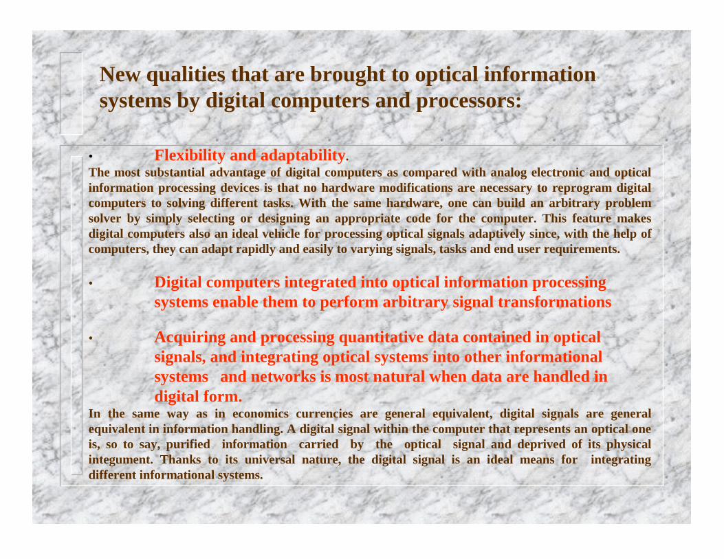
Digital Holography: Digital Reconstruction of HologramsM.A. Kronrod, N.S. Merzlyakov, L.P. Yaroslavsky, Reconstruction of a Hologram with a Computer, Soviet Physics-Technical Physics, v. 17, no. 2, 1972, p. 419 - 420

Computer simulation of coherent imagingCase study: Speckle noise in coherent imaging systems
Hologram
Hologram sensorMeasuring hologram orthogonal/ amplitude-phase components:
- Limitation of the hologram size
- Limitation of the hologram component dynamic range
- Hologram signal quantization
Reconstruction of the hologram
Reconstructed image
Diffusely reflecting
object
Reflected wave front
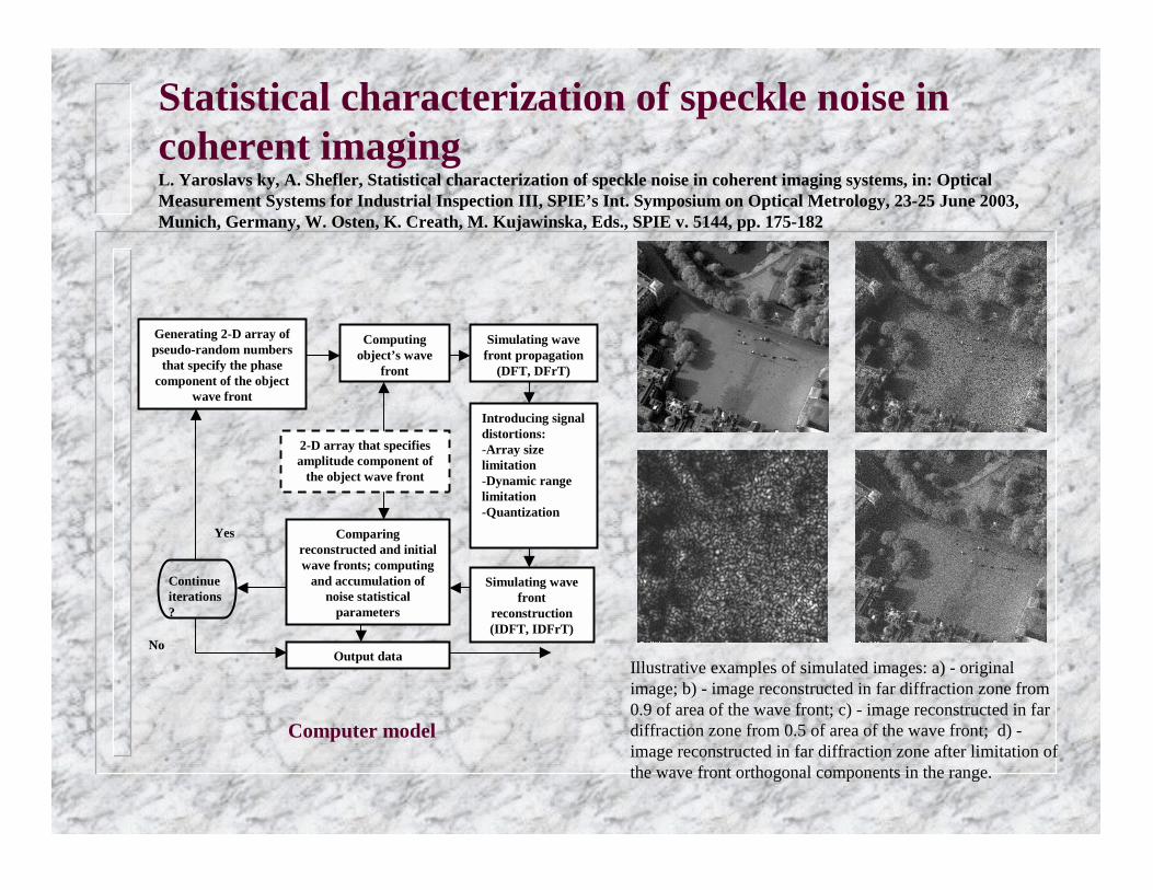
Statistical characterization of speckle noise in coherent imagingL. Yaroslavs ky, A. Shefler, Statistical characterization of speckle noise in coherent imaging systems, in: Optical Measurement Systems for Industrial Inspection III, SPIE’s Int. Symposium on Optical Metrology, 23-25 June 2003, Munich, Germany, W. Osten, K. Creath, M. Kujawinska, Eds., SPIE v. 5144, pp. 175-182
2-D array that specifies amplitude component of
the object wave front
Generating 2-D array of pseudo-random numbers
that specify the phase component of the object
wave front
Computing object’s wave
front
Simulating wave front propagation
(DFT, DFrT)
Introducing signal distortions:-Array size limitation-Dynamic range limitation-Quantization
Simulating wave front
reconstruction (IDFT, IDFrT)
Comparing reconstructed and initial wave fronts; computing
and accumulation of noise statistical
parameters
Continue iterations?
Yes
NoOutput data
Illustrative examples of simulated images: a) - original image; b) - image reconstructed in far diffraction zone from 0.9 of area of the wave front; c) - image reconstructed in far diffraction zone from 0.5 of area of the wave front; d) -image reconstructed in far diffraction zone after limitation of the wave front orthogonal components in the range.
Computer model

0.2 0.3 0.4 0.5 0.6 0.7 0.8 0.9 10
0.2
0.4
0.6
0.8
1
GrLv 1/82/83/84/85/86/87/88/8
Reconstructed images for different limitations of the wave front measured area
Speckle contrast as a function limitations of the wave front measured area
Speckle noise and sensor’s size in hologram reconstruction

Mathematicalmodel of the
object
Complex amplitude of
object wave field
Computation of mathematical hologram:-Fourier Transform-Fresnel Transform-Composition of spherical waves
Coding computer generated hologram
for recording
Recording computer generated hologram
Digital-to-analog conversion
Hologram usage model
Computer
Digital Holography:
Synthesis of Holograms and Diffractive Optical elements
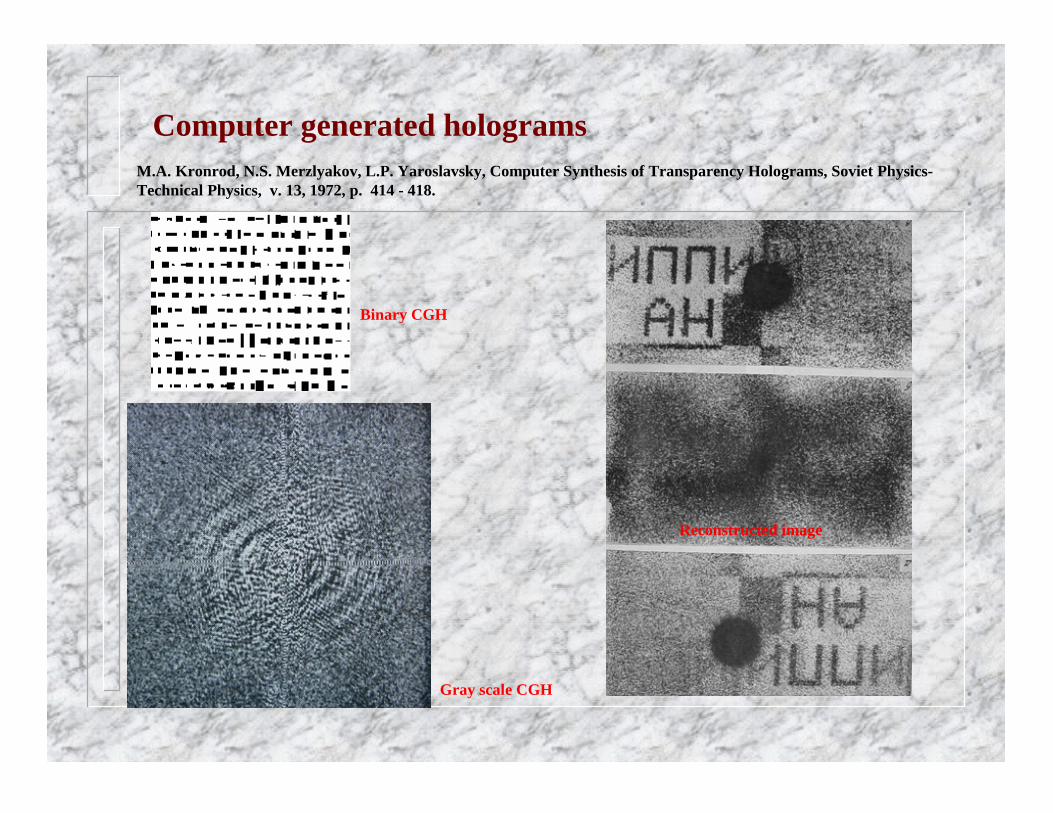
Computer generated holograms
Binary CGH
Gray scale CGH
Reconstructed image
M.A. Kronrod, N.S. Merzlyakov, L.P. Yaroslavsky, Computer Synthesis of Transparency Holograms, Soviet Physics-Technical Physics, v. 13, 1972, p. 414 - 418.
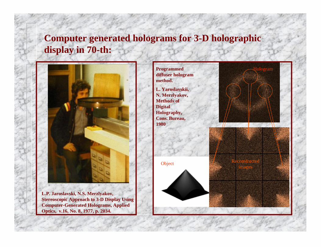
Computer generated holograms for 3-D holographic display in 70-th:
L.P. Jaroslavski, N.S. Merzlyakov, Stereoscopic Approach to 3-D Display Using Computer-Generated Holograms, Applied Optics, v.16, No. 8, 1977, p. 2034.
Reconstructed images
Programmed diffuser hologram method.
L. Yaroslavskii, N. Merzlyakov, Methods of Digital Holography, Cons. Bureau, 1980
Hologram
Object
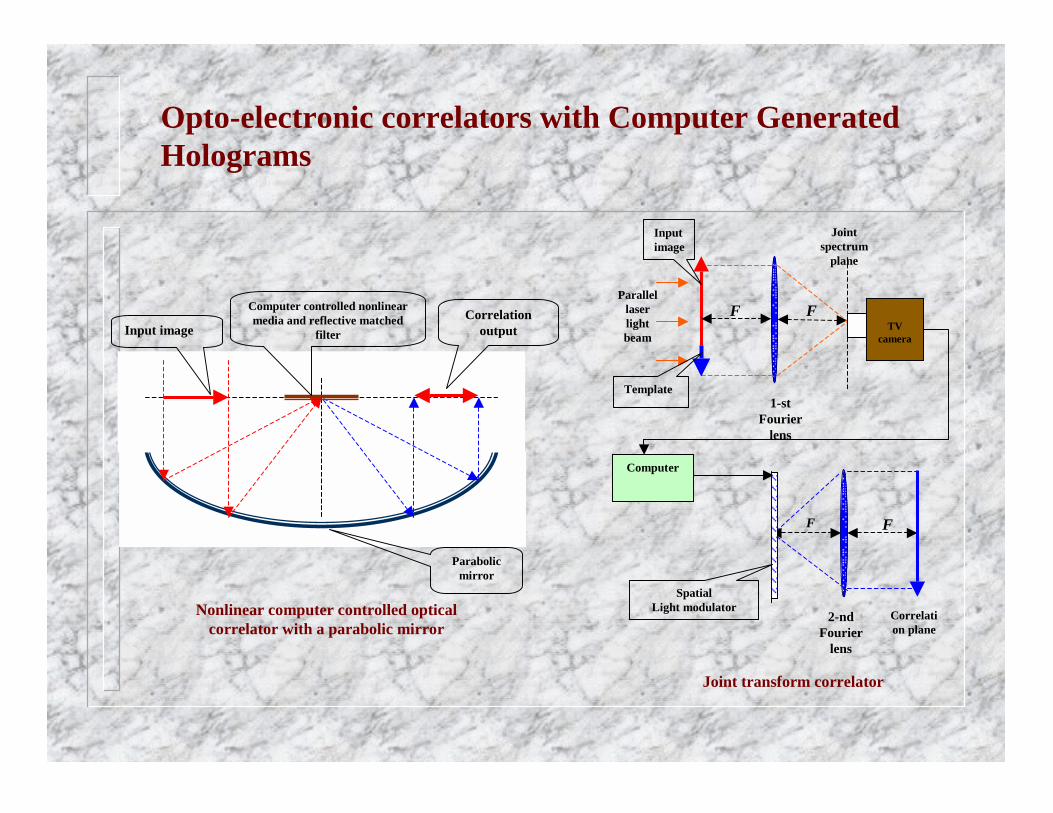
Opto-electronic correlators with Computer Generated Holograms
F F
1-stFourier
lens
Parallel laser light beam
Input image
Template
TV camera
Correlation plane
F F
2-ndFourier
lens
SpatialLight modulator
Computer
Joint spectrum
plane
Input image
Computer controlled nonlinear media and reflective matched
filter Correlation
output
Parabolic mirror
Nonlinear computer controlled optical correlator with a parabolic mirror
Joint transform correlator
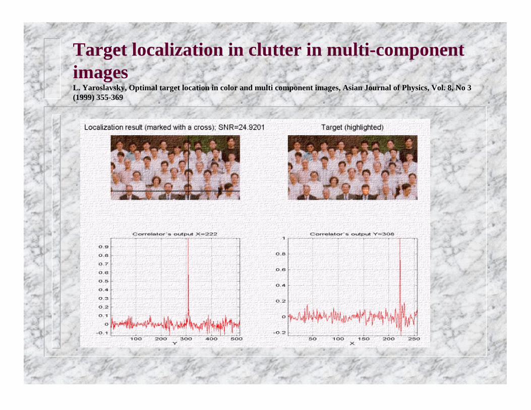
Target localization in clutter in multi-component imagesL. Yaroslavsky, Optimal target location in color and multi component images, Asian Journal of Physics, Vol. 8, No 3 (1999) 355-369

Optimal adaptive correlators: detection of microcalcifications in mammograms
Detection and enhancement of microcalcifications in a mammogram
Input mammogram

Object tracking in video sequencies: examples
Tracking fetus
movements in
Ultrasound movie
For details see http://www.eng.tau.ac.il/~yaro
Leonid P. Yaroslavsky, Ben-Zion Shaick Transform Oriented Image Processing Technology for Quantitative Analysis of Fetal Movements in Ultrasound Image Sequences. In: Signal Processing IX. Theories and Applications, Proceedings of Eusipco-98, Rhodes, Greece, 8-11 Sept., 1998, ed. By S.Theodorisdis, I. Pitas, A. Stouraitis, N. Kalouptsidis, Typorama Editions, 1998, p. 1745-1748

Face detection in complex imagesBen-Zion Shaick, L. Yaroslavsky, Object Localization Using Linear Adaptive Filters, 6th Fall Workshop, Vision, Modeling And Visualization 2001 (Vmv01), November 21-23, 2001, Stuttgart, GermanyStuttgart, Germany, November 21-23, 2001, pp. 11-17

Digital image processing in 70-th:Mars-4 and Mars-5 (1973), Venera-9, Venera-10 (1975) T.P. Belikova, M.A. Kronrod, P.A. Chochia, L.P. Yaroslavsky, Digital Processing ofMartian Surface Photographs from " Mars-4" and " Mars-5", Kosmicheskiye Issledovaniya, v. 13, iss. 6, 1975, p. 898-906
First panoramic images from Venus surface: Venera-9, Venera-10
Images from Mars orbiter Mars-4/5: before and after rectification

First color image of Martian surface synthesized by computer processing (Mars-4, Mars-5, 1973)D.S. Lebedev, M.K. Naraeva, A.S. Selivanov, I.S. Fainberg, L.P. Yaroslavsky, Synthesis of Color Images of the Surface of Mars from Photos, obtained from the Space Station "Mars-5", Doklady of the USSR Academy of Sciences, ser. Mathematics and Physics,v. 225, No. 6, 1975, p. 1288-1292.
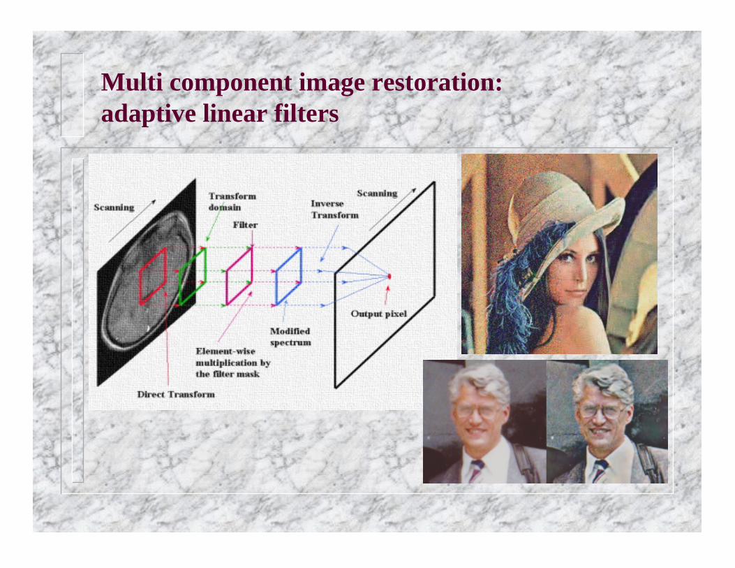
Multi component image restoration: adaptive linear filters

Restoration of high resolution satellite imagesL. Yaroslavsky, High Resolution Satellite Image Restoration with the Use of Local Adaptive Linear Filters, Report on
Keshet Program, July, University Dauphine, Ceremade, Paris,1997
Spot-image: before Spot-image: after
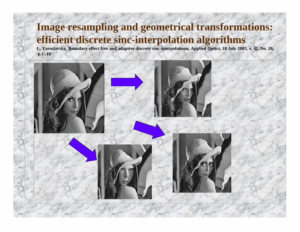
Image resampling and geometrical transformations: efficient discrete sinc-interpolation algorithmsL. Yaroslavsky, Boundary effect free and adaptive discrete sinc-interpolatioon, Applied Optics, 10 July 2003, v. 42, No. 20,p.1- 10

Direct Fourier method for inverse Radon transform:polar-to- Cartesian coordinate spectrum conversion with discrete sinc-interpolation(L. P. Yaroslavsky, Y. Chernobrodov, Sinc-interpolation methods for Direct Fourier Tomographic Reconstruction, 3-d Int. Symposium, Image and Signal Processing and Analysis, Sept. 18-20, 2003, Rome, Italy)
Object
Projections
Projection spectra
Interpolated 2-D object spectrum
Reconstructed image

Spectrum/correlation analysis with sub-pixel resolution
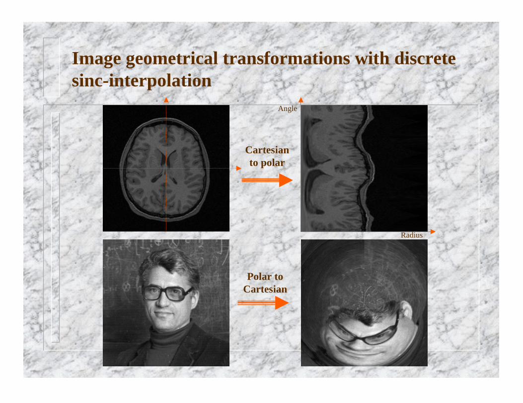
Image geometrical transformations with discrete sinc-interpolation
Radius
Angle
Cartesian to polar
Polar to Cartesian
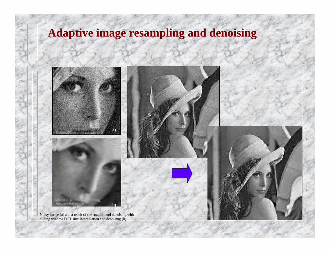
Noisy image (a) and a result of the rotation and denoising withsliding window DCT sinc-interpolation and denoising (b).
a)
b)
Adaptive image resampling and denoising

Image restoration and enhancement: nonlinear filtersL. Yaroslavsky, Nonlinear Filters for Image Processing in Neuromorphic Parallel Networks, Optical Memory and Neural Networks, v. 12, No. 1, 2003
Noisy image, stdev = 20, Pn=0.15
Iterative SCSigma-filter . Wind. 5x5, Evpl=Evmn=15; 5 iterations

Initial image SIZE(Evnbh(Wnbh5x5,2,2))-filter HIST(W-nbh)-filter
Nonlinear filters: Image enhancement
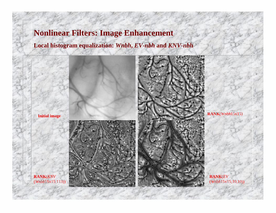
Initial image
RANK(KNV(Wnbh15x15;113))
RANK(Wnbh15x15)
RANK(EV(Wnbh15x15;10,10))
Nonlinear Filters: Image EnhancementLocal histogram equalization: Wnbh, EV-nbh and KNV-nbh

Local P-histogram equalization: color images(blind calibration of CCD-camera images)

Computer synthesis and display of stereoscopic images
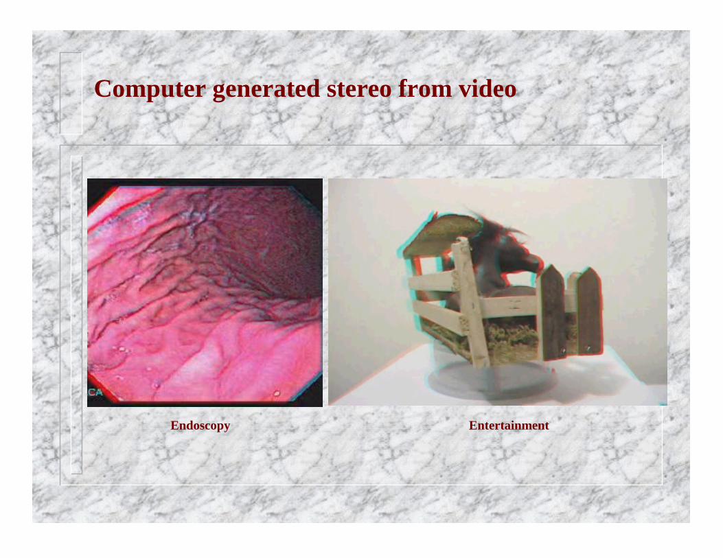
Computer generated stereo from video
Endoscopy Entertainment
Top Related