


Languages
Pages
Legal

01/01/2008 17:57:38
IFAS: Interactive Flexible Ad Hoc Simulator
Yosi Ben-Asher, Moran Feldman, Sharoni Feldman
Computer Science Department, Haifa University, Israel.
Yosi, Sharoni{@cs.haifa.ac.il}
.
Abstract
Ad Hoc networks are characterized by fast dynamic changes in the topology of the
network. Introduction of new routing algorithms requires a deep and trustworthy
evaluation process. In this paper we describe an Interactive Flexible Ad Hoc
Simulator (IFAS) that presents a modern and novel approach to the family of Ad Hoc
simulators. This simulator supports unique viewing, debugging, tuning and
interactive capabilities that shorten significantly the design and debug process of new
algorithms. The development of the IFAS is still going on; however we see this new
simulator as an innovative tool that will stand in line together with other traditional
simulators.
1. Introduction and Related Work The development of distributed ad hoc routing protocols requires a long development
path. A network simulator is a mandatory and essential development tool. The initial
development phase is dedicated to the basic debugging of the new algorithm and in
advanced phases the simulator is required to support performance analysis. Our
expectation is that the simulator will be able to simulate even more advanced tasks
like potential applications that make use of the algorithms. In addition to the ability of
the simulator to simulate a real ad hoc environment, we expect it to support the users
with a variety of services in order to ease the development and the debugging phases.
Moreover, we challenge it to present an infrastructure and additional services for
further developments of applications that lean on the new algorithms. A very
important factor is the ability of the simulators to simulate a large scale theater with
hundreds of nodes, within a reasonable time.
There are a number of network simulators available for ad-hoc simulations. The most
known simulators are NS-2[9], OPNET[10] and GloMoSim[11]. These simulators
01/01/2008 17:57:38
provide a simulation environment which is supposed to reflect the real world.
Naturally we expect the gap between the results presented by the simulators and the
real world and among the different simulators to be minimal. In [6] such a comparison
was performed, and the conclusion was “..We have collected very different results,
barely comparable”. These tests were performed on a simplistic environment with 50
nodes moving in a terrain of 1km × 1km. The different results are explained with a
very different implementation of the physical layer even if the same physical
parameters were selected.
The issue of the simulation time needed to examine a problem is discussed in [7]. A
10 second simulation of 300 nodes in an area of 3km × 3km using the NS-2 simulator,
required 1000 seconds on a standard PC. The expectation to make 10 runs of 600
seconds each, are translated to more than a week in real life. This large time frame
does not allow an “online debugging” of the algorithms. Moreover, these timeframes
minimize the ability of the developers to get some online feedback from a simulator
GUI by watching the behavior of the networks elements, the dynamic data structures,
the sessions’ creation process and the messages transfer.
An interesting insight is presented in [5] where the authors say that “Often
understanding a simulator with its whole complexity is virtually impossible, which
can sometimes lead to wrong usage and thus erroneous or misleading simulation
results”. The authors present the concept that sometimes using a full network
simulator is like using heavy artillery when there is no need for it. These
understandings lead them to present a simulator that is a more intuitive and
understandable tool.
We have developed the Interactive Flexible Ad Hoc Simulator (IFAS) as a
comprehensive environment used to develop tests and analyze ad hoc routing
protocols and as a foundation that runs applications using the routing algorithms. The
dynamic nature of this ad hoc oriented simulator introduces set of online tools and
visual instruments that significantly increase the understanding of the routing protocol
and the applications behavior and decrease the debugging and analysis time.
IFAS provides a broad list of options for the transport and data link layer with an
abstraction for the physical and data link layers. It was planned to be used for 3D
simulations and it uses a 3D radio propagation model including physical obstacles like
buildings that interpose between transmitters. The simulator includes a set of

01/01/2008 17:57:38
functions that can be used during the execution phase to support the online analysis
and hosts a set of tools that can be used on the output log files created during the run.
The IFAS which was built on top of the .net framework, using ActiveX technology,
activates both internal and external utilities. This framework supports a set of
programming languages like C#, J# and Managed Extension for C++.
2. IFAS design concept
The main motivation for building “yet another ad-hoc simulator” is that each ad hoc
routing algorithm must be tuned and corrected not only to improve its performances
but also to reveal failing situations not anticipated by the user. Moreover, these failing
situations can be detected only through detailed simulations and careful coverage of
different input scenarios. For example, it may turn out that the underlying algorithm
does not handle well cases where there are relatively small dense areas in parts of the
simulation theater. In order to solve such a case the user may add some randomness in
the selection of alternative routing paths, so that more sessions will pass in the
proximity of the dense area rather than within this area.
We distinguish between two types of failing cases:
• Local cases wherein the failure is limited to a small area in the theater. The global
performance may not be affected by this local failure.
• Global cases that affect the overall average performances that can not be
characterized by any local configuration. For example, there might be a
connection between the frequency in which nodes change their moving direction
and the size of the queues wherein incoming packets are stored.
The IFAS simulator offers two mechanisms for detecting and covering such “hidden
failing cases”:
• An interactive highly visual display wherein the user can view each simulated
node and change its setting during the simulation. This visual display is useful for
the detection and creation of local failing cases. This display includes additional
views of the communication links, the voice and data sessions, control data etc..
There is an extensive use of zooming, colors, line types and symbols to overcome
the highly dense simulation theaters usually used in ad-hoc simulations (order of

01/01/2008 17:57:38
500 nodes). A typical example of using the visual display is to locate a “critical”
node which serves many voice/data sessions and delete it in order to see if the
algorithm can recover and re-rout the sessions originally passed through this
deleted node.
• An advanced query system which is used for the analysis of detailed log files
obtained after each run of the simulator. In addition, it is possible to "replay" a log
file. In this case, events like node emerging, node disappearance and node
movements are not selected randomly but extracted from a log file. This feature
enables the users to isolate and test specific elements and compare the effect of
very minor changes. The "replay" capability enables the users to make a fair
comparison between different protocols by running the same log under the various
protocols.
This simulator was designed and constructed with an emphasis on features which give
the user a tool which is user friendly, easy to use and allows broad operational
abilities such as:
• Intuitive parameters management and tuning including default parameters, simple
navigation between windows and real time control on the testing theater. The user is
protected from accidental changes of parameters by two tier protection.
• Near real time network simulation where the simulation pace is similar to the real
time. By viewing the development in the theater, the user understands the
misbehavior of the protocol and is able to investigate it during runtime. It is done by
freezing the theatre, moving step by step and debugging the protocols and the
applications.
• Openness to any ad hoc protocol. Our basic development focused on AODV[1]
and MRA[2]. However, additional protocols can be added and use the existing
infrastructure and classes.
• Flexibility to define various types of nodes with different attributes like personal
transmitters (people), Car mounted transmitters, UAVs, Helicopters and GEO
satellites etc. In addition, applications running on top of the ad hoc protocols, may
use other types of nodes with specific capabilities for their needs.
• Adjustable link properties like inbound and outbound queue sizes, bandwidth and
radio parameters.

01/01/2008 17:57:38
• Interfaces to external standard mathematical libraries used for post simulations
analysis.
The Logical structure of the IFAS simulation environment is presented in Figure 1.
The major building blocks will be described in the rest of this document.
Figure 1: IFAS: Logical Breakdown
The modular architecture of the IFAS creates a working environment that enables the
users to add new capabilities. For example, there are basic classes that may be used to
add new entities. The messaging layer enables the developer to add new protocols.
New messages required by new protocols will be inherited from the abstract base
class "IP_Message".
New entities can be added to the entities bank of the IFAS. An entity is constructed of
two main elements: a transmitter and movement capabilities in the 3D space. All
entities are based on a single class - "Telephone". Additional features can be added as
plug-ins to this class. For example, the IFAS currently supports Geo-stationary

01/01/2008 17:57:38
satellite. It is possible to define a new entity as Low Earth Orbit (LEO) that is visible
to the nodes in the theatre for a short time every 90 minutes.
The following chapters describe in detail the unique features of the IFAS.
3. Online Debug and Tuning
Run time View
Figure 2 presents the runtime view. The major part of the screen is dedicated to the
deployment of the transmitters in the theatre. Every symbol presents a different type
of a transmitter. A circle presents a hand carried transmitter, a triangle presents a
UAV etc. Numeric values inside the symbols and on the links present the current
number of sessions that pass via a node or a link. A dashed line presents a radio link
while a full line presents a logical connection between links. The right side of the
screen is dedicated to online tracing functions and online control buttons. A click on a
node will present its status in the right side of the screen. The values change in real
time due to the node movement and its activities in the network. The main details that
appear in this window are: node speed and direction, number of neighbors, node
location and number of sessions. In addition it displays protocol dependent variables
like the MRA node coordinates. The MRA arranges the nodes in trees. The
coordinates of the node in the tree are not fixed and change frequently due to node
movement. Every node has an inbound queue and an outbound queue. Every message
generated by the applicative levels in the node is stored in the outbound queue. Using
FIFO policy, the node tries within every clock tick to send the oldest message from
the queue. Messages trying to enter a full queue will be lost. A similar inbound queue
exists for incoming messages. The analysis of the queues enables a trained viewer to
observe exceptional and unexpected behavior. It is possible to get a detailed view of
the queues in real time by pressing the queue summary button. A new window is
opened and presents the content of the queues in real time (The small window in the
right-bottom side of Figure 2). The online analysis of the detailed queues content may
raise interesting issues. For example, the initial definition of the MRA protocol
required every node to send periodically a registration message. Using this window
during simulative runs revealed the fact that the load on certain nodes created by the

01/01/2008 17:57:38
registration messages is beyond our expectations. This visual-online tool brought up
the need to optimize the registration process and led to a different design that reduced
the number of messages.
The queues size can be adjusted according to the node type and the expected load (the
load is composed of transit traffic where the node acts as a router, and traffic
generated by the node when the node acts as a session originating node or session end
node).
Figure 2: RunTime View
Other control options on the right side enable the user to view the overall
performance, by analyzing global values, “eliminate” selected nodes, change life
cycles of nodes to become immortal where they do not disappear, stop session's
activation etc. The life cycle of a node is composed of a set of random events like
emerging in the theatre, moving, changing direction and speed, node disappearance
etc. These control options enable us to isolate and analyze events that hide under the
broad flow of events. Sometimes the tracing tools expose a problem and the analysis
is performed with additional offline tools that extract the relevant data from the logs.
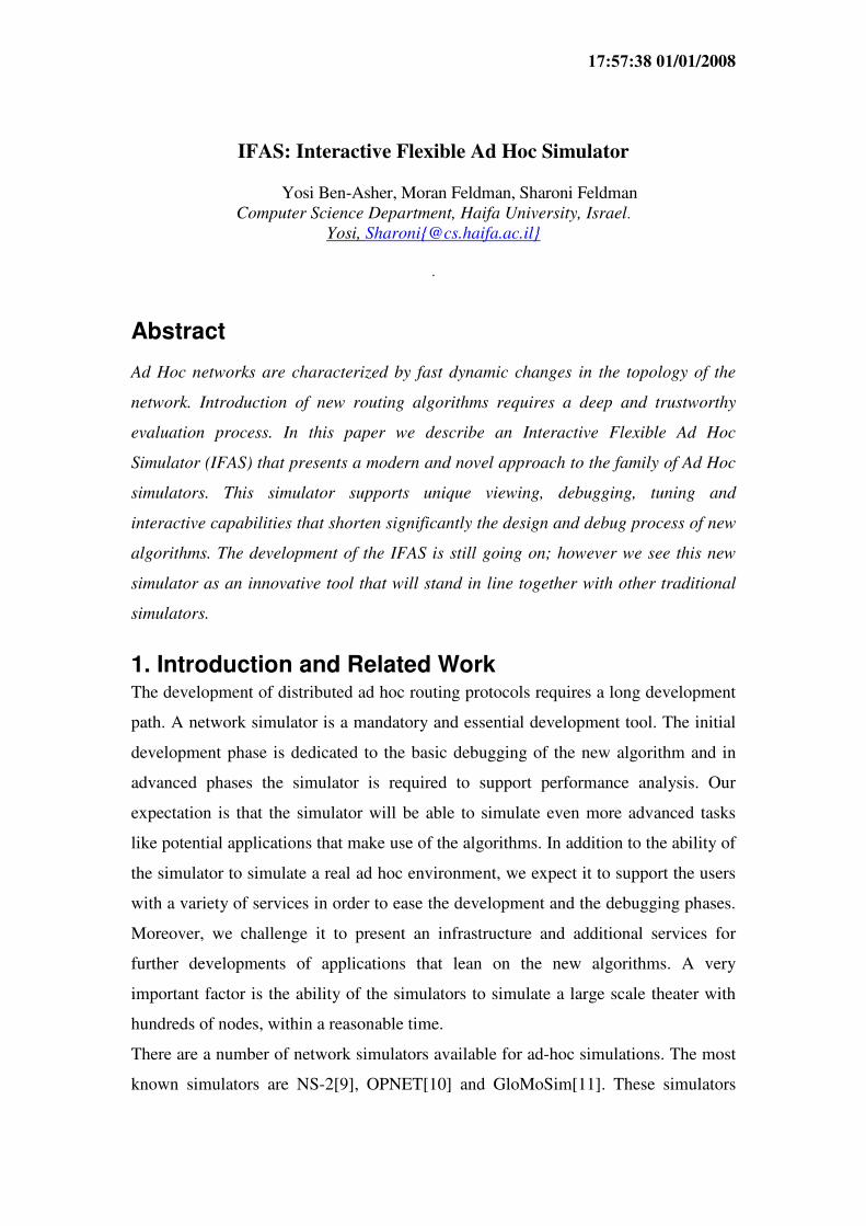
Figure 3 presents an example of one offline screen that summarizes the abnormalities
during a test run. This screen depicts the distribution of the session termination
reasons.
01/01/2008 17:57:38
By using these options, during the development of the MRA protocol, we isolated rare
cases where the trees formation process entered a long unexpected negotiation phase
between adjacent nodes. This long negotiation process ended finally with the expected
result, however, it exposed the need to calibrate this process. Furthermore, the process
revealed directions for the simplification of the migration process which fuses
separate trees into a single tree.
Figure 3: Offline message summary message analysis
Another interesting global phenomenon was detected using the visual capabilities. We
noticed that the trees generated by the MRA were not balanced as expected. An
unbalanced tree leads to the accumulation of control traffic in some nodes and
creation of long session paths. This insight was implemented in additional rules to the
tree formation process which resulted in the creation of balanced trees.
4. Special Features and Nodes
Radio Propagation Model (RF)
The RF model is used to describe the radio propagation between any two nodes in the
theater. The RF model is controlled by the Simulator control screens. It uses the
Effective Radiation Power (ERP) formulas:
1. RF propagation free space transmission between two points at distance d is given
by: )log(205.92 fdLoss ××+= Where d is in Km and f is GHz
2. RF propagation for antennas that are near the ground, the loss between a
transmitting node and a receiving node is defined by the following formula:

01/01/2008 17:57:38
)log(20)log(40 HrHtdloss ××−×= Where d is distance between antenna in
meters and Ht and Hr is the height of the transmitter and the height of the receiver
in meters.
3. Any physical obstacle increases the loss by 5dB.
Similarly to the management of the RF model, it is possible to manage the links
bandwidth, packets transmission rate etc.
MAC Model
In Ad-Hoc networks, Medium Access Control (MAC) schemes are used to control the
access of active nodes to the Radio channel. The IFAS uses a MAC model based on
IEEE 802.11[12] wireless LAN standard. The 802.11 standard specifies a common
MAC layer based on coordinating access to shared radio channel. The control is
performed by reservation of access to the radio channel using the RTS/CTS (Ready-
To-Send / Clear-To-Send) dialogue. A ready node sends a RTS message trying to
reserve the usage of the channel. When the RTS message is received, the intended
receiver replies with CTS acknowledging the successful reservation of the channel.
An exception to this model exists in case of a Geo-stationary satellite. These entities
act only as routers. The long delay of 0.2 seconds caused by the orbiting in an altitude
of 36,000Km prevents the use of he RTS/CTS mechanism.
The MAC model is implemented in a single class named "MAC". An instance of the
MAC class is invoked by every entity in the theatre.
Nodes and Movement Model
The IFAS currently supports the following nodes: personal transmitters, transmitters
mounted on cars, transmitters carried by UAVs and Helicopters and GEO satellites.
An additional application uses missiles and targets. All nodes have different and
independent characteristics like different moving profiles, different transmission
range and different bandwidth. A special option allows controlling the battery of the
personal transmitter and tracing the power usage. When this option is activated, every
transmission withdraws power from its battery while another option allows online
recharging of the battery during operation.

01/01/2008 17:57:38
In case of free movement, a node starts to move with a random speed selected from
the relevant range as presented in Table 1. The node moves in this direction for a
certain period of time until it changes its direction. A node that reaches the border of
the theatre will be "reflected" back into the field.
Speed in Km/h (meter/sec)
Type of Node Min-Speed Max-Speed Persons 5 (1.38) 9 (2.5)
Cars 50 (13.8) 80 (22.2)
Helicopters 120 (33.3) 150 (41.6)
UAV's 90 (25) 120 (36.1)
GEO Fixed position – alttitute 36,000 km
Missle Constant speed of 720 Km/h
Targets 50 (13.8) 80 (22.2)
Table 1: Nodes Movement Speed Range
Sessions Model
The session model supports voice and data sessions. A voice session is a session
where the end nodes exchange packets. In a dada session files are transferred from the
source node to the end node.
Sessions Traffic Management
The users have a full control of the number of active sessions, the mixture of the voice
and data sessions. For voice sessions, the users define the duration range and for data
sessions the files sizes are defined. In a similar way to voice over IP (VoIP) services,
the IFAS allows the users to define the number of packets that will be transferred
every second and the packet size. The bandwidth handled by a node can be adjusted
and is divided to a number of channels. One channel is dedicated for signaling and
this channel is common to all sessions that use the node. Another channel is dedicated
to a session that may start or end in the node. Each one of the left channels serves
sessions where the node acts as a router. The number of channels can be tuned
according to the node type. For example, in our simulations a personal transmitter
handles 10 channels and a transmitter mounted on a helicopter handles 30 channels.
Multiparty sessions
IFAS supports several types of sessions. Every session is initiated by the "originating
node" to one or more nodes called "target node(s)". The simulator supports the
following types of sessions:

01/01/2008 17:57:38
1. Bidirectional sessions. The bidirectional sessions are full duplex, where the
originating node and target node exchange packets. Both data streams use the
same path.
2. Unidirectional sessions. This type is divided into 3 different categories according
to the number of target nodes.
2.1 Unicast session. The source node creates a unidirectional session and sends
data towards the destination node. A low Quality of Service is handled by the
following methods:
2.1.1 Retransmissions of lost messages.
2.1.2 Dynamic allocation and de-allocation of additional paths that distribute
the load over the network.
2.2 Multicast sessions – A single source node sends a file to a group of target
nodes.
2.3 Broadcast sessions – A single source node sends a file to all nodes in the
network.
Sessions Initiation
A monitor in the simulator traces the number of active sessions. In case that the
number of active sessions drop bellow the predefined values, the monitor will
randomly select an originating node and an end node. The monitor will stimulate the
originating node to initiate a session towards the end node. The session creation
process may fail because of a number of reasons such as a lack of resources, no
available path between the nodes etc. Other parameters define the number of retries of
the originating node trying to establish a path and the maximal time that can be used
by this process.
The user can initiate manually sessions between specific nodes with certain
parameters. Figure 4 presents the manual session initiation screen and its parameters.

01/01/2008 17:57:38
Figure 4: Manual Session Initiation Screen
Design Area
The area user enables the users to define obstacles in the theater. Obstacles placed in
between communicating nodes reduce significantly the radio signal among them. An
example of how obstacles appear in the theatre can be seen in the upper part of
Figure 2. A moving node can not pass via an obstacle. As soon as the node
approaches an obstacle it will change its moving direction.
The IFAS supports the definition of “Gravity Centers” (GC) for every node type. A
GC is a location in the theater selected by the users. The gravity center controls the
distribution of the nodes in the theater. The default “gravity” is 1 and it means that all
nodes are distributed evenly in the theater. A value higher than one will concentrate
more nodes around the gravity center. The density of the nodes grows as the value
grows. The opposite effect is achieved by using fractions from the range (0..1).
Group Mobility
The group mobility supports relationship among mobile nodes. It allows the users to
drag and drop "platoons" in the theatre with dedicated movement capabilities. While
the platoons move in the theater according to a set of rules, the mobile nodes inside a
platoon move according to the node nature. The tests users are able to define what
type and the number of nodes will populate every platoon. Every platoon has a
mobility model of its own. The usage of platoons is important when the theatre is very

01/01/2008 17:57:38
large and the nodes are arranged in units. Figure 5 presents a snapshot of the simulator
display with 3 platoons and 50 nodes populating the platoons.
Another use of platoons is the ability to define flying corridors for aircrafts. By
defining the platoon as a stationary platoon and setting the appropriate parameters, it
is possible to control the flight path and flight cycle of an aircraft.
Figure 5 :Platoons in the field
The IFAS group mobility model is similar to the Reference Point Group Mobility
(RPGM) [11]. Each platoon has a logical center. The center's motion defines the
entire platoon motion behavior. A node that belongs to a platoon can not leave its
platoon. Platoons can pass through platoons. The whole theater can be defined as a
platoon. In this case smaller platoons will be contained within the global platoon.
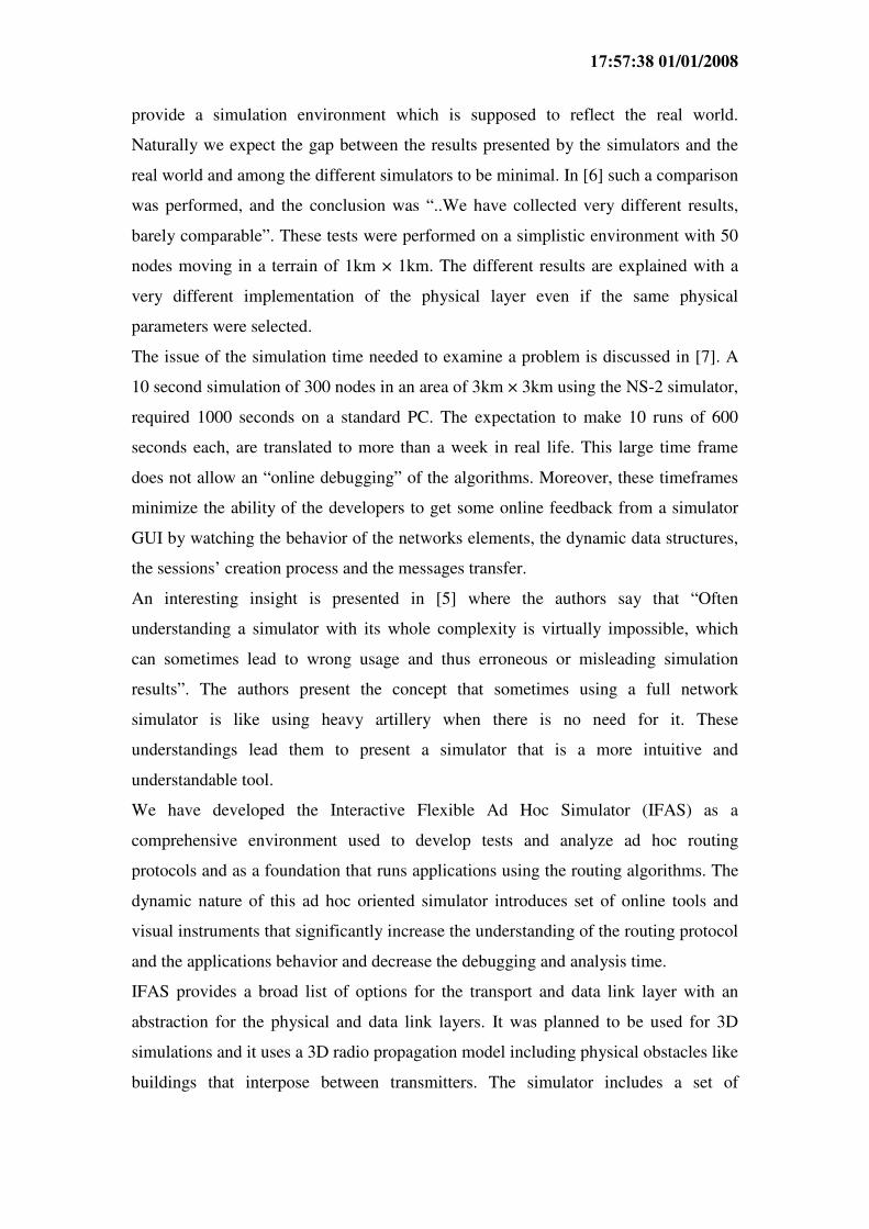
Logs and Scenario management
The IFAS hosts a set of tools that enables the users to run a series of tests, record all
events into logs and analyze the results using offline utilities. These tools enable the
developers to extract the relevant information from the logs. A typical log of a 60
seconds run with 300 nodes holds 400 MB.
01/01/2008 17:57:38
Figure 6: Sample of successful sessions report
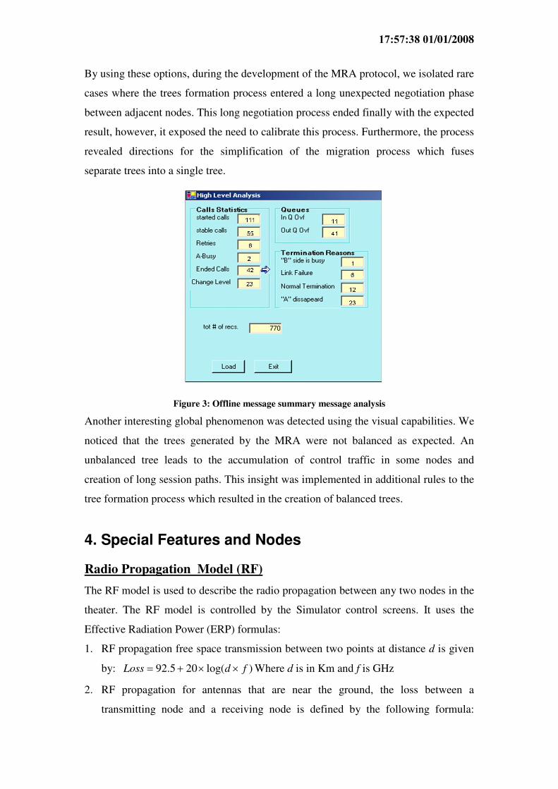
Applicative Layer
The IFAS can run applications that use the Metrical Routing Algorithm (MRA) as a
communication layer used by an application. Currently, two applications were
Figure 7: Application view of UAVs, Targets and Missiles

01/01/2008 17:57:38
developed Task assignment and flocking applications [13]. Both applications utilize
the communication infrastructure of the MRA and its agility to connect nodes. The
advantage of using the IFAS as a platform to develop and test applicative algorithms
comes from the following (1) the set of interface procedures to the communication
layer (2) the IFAS wide set of analysis and testing tools that support the development
of the applicative algorithms and (3) the IFAS visualization capabilities. Figure 7
presents an application of a flock of UAVs illustrated by triangles chasing potential
targets illustrated as "packmans". In case that an application is running, the nodes
follow the movement needs of the application under the limitations of the movements’
model. For example, in case that the UAVs are flying with active flocking, the UAVs
flight directions and speeds are adjusted according to the numerical calculations
presenting the flocking model. In addition to the UAVs and targets, Figure 7 presents
missiles illustrated by the red dots fired by the UAVs toward the targets. Note that the
potential targets and missiles move autonomously without any radio connection
among themselves.
5. Implementation Complexity
The IFAS was developed using Microsoft “.net” environment. The total code base of
the IFAS and its utilities is 40,000 lines. The IFAS is constructed of two threads:
1. Graphical management thread that is activated several times every second. This
thread handles the current view on the screen.
2. Simulation Control thread responsible for advancing the tick-manager followed by
the other modules.
We will describe the main modules constructing the IFAS. In the following part we
will use the terms node and transmitter with an identical meaning.
• Tick-manager (TM): The TM is the module responsible for the time advance in
the simulations. In our simulations we used a pace of 330 ticks per second; if
needed, this parameter can be adjusted to support applications that require smaller
segments of time. The TM has two states: Pause and Executing. Every node in the
theatre is required to act according to the time ticks and therefore it must register
to the time services. Every node in the theatre gets a signal from the TM
indicating that time is advanced.

01/01/2008 17:57:38
A special feature “over-ticking” requested by a node during the registration time
allows the nodes to operate in a pseudo-asynchronous mode. In this case, every
node may perform a set of actions in one tick.
• Node-Life-Manager (NLM): This module generates nodes randomly. In every
tick, this module decides whether to generate a new node, where to put this node
in the theatre or maybe to locate it inside a platoon and what is the life span of this
node. In addition the NLM defines the node speed and initial movement direction
where the movement direction can change during the simulation.
A special running mode is when the NLM runs in a “playback” mode. It gets its
operational directions from a log file recorded in previous runs. There is an NLM
instance per any type of node. A special class Position-allocater determines the
distribution of the nodes in the field. Two distribution models exist – “Random
distribution” and “Gravity Center distribution”.
• Connection-Manager (CM): Every active node in the theater registers itself as an
active node in the CM. The CM maintains the database for the Presentation-
Manager responsible for data viewing and online management. In every tick the
CM updates the new position of the nodes that changed their position. The CM
serves the MAC layer. Using the CM services, the MAC layer determines whether
every two nodes are within transmission range of each other. The transmission
range analysis performed by the CM uses the unique characteristics of every node
including flying nodes, nodes that move on ground, satellite etc.
• Transmitter (TR): The TR represents all different transmitters. Every TR is
responsible for its movement and when requested, it will report to the Display-
Manager on its movement. Every TR manages its own resources. For example, the
power charged in a portable transmitter battery is a resource handled by the TR.
The TR can be configured according to the needs (Aerial or land moving) and the
relationship between every TR and the other TR types in the theatre. The
configuration is done with a dedicated Configuration-Model (CM) that supports
all possible parameters. Every TR accesses the appropriate entry in the CM and
01/01/2008 17:57:38
selects the relevant information defining its operation mode.
The TR is capable of working in a replay mode on recorded scenarios. The TR
contains and uses sub-modes that define the movement models of the nodes and
control their movement (as long as they are not in replay mode).
Every node has an interface to the MAC layer that controls the exchange of
messages. The MAC supports transmission delays which are essential for
satellites. An important feature is the support to the logging functions.
Every TR has a protocol that handles its ad hoc protocol characteristics. In our
current implementation the protocol can be either AODV or MRA.
Our implementation method decouples the linkage between the TR and the ad hoc
protocol as the TR can select any protocol during the initialization time from the
configuration definition.
• Design Area (DA): The DA is constructed of a window on which one can draw
nodes (Drag and Drop). It is irrelevant to the DA what the nodes in the theatre are
and the nodes draw their own appearance on the design area. All nodes on the
design area are templates that change into real nodes when the system changes its
running mode to “executing”. This way of implementation eases the management
of the nodes library as there is no need to handle run time details. The DA
supports the following distribution models: Gravity Center, Platoon User and
satellite User. It is possible to add more models according to the application needs
without code changes.
• Platoon: This node is similar to the basic TR node. It gets a location and
movement direction in the theater from the user and moves according to
predefined movement model. The discrete transmitters in the platoon are
responsible for their stay inside the platoon.
• Logging: Every time a simulation is launched and logging is requested, a new set
of log files is opened. The set is composed of two files. The first file is accessed
by every node that wants to write into the log and a second one is controlled by a
dedicated class Queue_Logger that scans the queues in every tick and updates

01/01/2008 17:57:38
changes. The information gathered by the Queue_Logger will be used in a
thorough analysis of the queues.
• IPmessage: The IFAS is designed to support any ad hoc protocol. This module
supports the basic services of the messaging system. When a message is sent, it is
encapsulated with information describing the message type, source and
destination. All protocols inherit their messages definition from IPmessage.
Menus and parameters: The manipulation of parameters used during the
simulations is carried through windows menus. A special mechanism is
responsible to store the changing values of the parameters. According to the
definitions in the configuration manager this mechanism makes completeness,
correctness and range checks on all values. As soon as the run ends, this module
stores the new values on a disk for future runs. Figure 8 presents the
Configuration manager parameters definition screen. The user can define the type
of every variable, the borders and default value. Whenever needed, it is possible to
return to the default values.
Figure 8: Configuration Manager – Parameters Defenition
• Display Windows (DW): The DW hosts interactive tools and manages the display
area. The DW manages the parameters area that displays variables that are
extracted regularly from the transmitters. This extraction is performed in two
levels – a global and a transmitter level. The DW supports basic operator
commands like Pause, Continue, Eliminate node, Generate session etc.

01/01/2008 17:57:38
• Obstacles: A dedicated window is used to define the obstacles in the theatre as
presented in Figure 9. Prior to the actual start of a simulation, the IFAS builds a
map of the theater with the appropriate decrease in the transmission power
according to the obstacles location. This table which is stored on disk can be
presented to the users and is used by the (CM).
.
Figure 9: Obstacles Defenition Window
• Scenarios: scenarios are generated by processing the log files. The relevant
information is extracted from the log and it contains the movement details, nodes
emergence and disappearance. A scenario can be stored and replayed when
needed.
6. Conclusions and future work
The design, development and debugging of a new ad hoc routing protocol require a
very massive phase of detailed tests, performance analysis and comparison to the
capabilities of other protocols. The common simulators present rich environments that
contribute to trustworthy tests. However, the usage complexity of the simulators and
the unexplained diversity of the results open the door for a new powerful simulator.
The IFAS uses the newest technologies and leverages the debugging and analysis
capabilities and as a result shorten significantly the development process.
The feedback we received so far, encourages us to extend the IFAS simulator by
adding additional features and improving the drawbacks. Our experience shows that
the easy use of the simulator and its seamless installation process contributes
significantly to the migration and knowledge transfer of the MRA protocol to an
operational environment based on C++.
01/01/2008 17:57:38
7. References
[1] C. E. Perkins, E. M. Royer, “Ad hoc on-demand distance vector routing,” in Proceedings of the 2nd
IEEE Workshop on Mobile Computing and Applications, New Orleans, LA, February 1999, pp. 90-
100.
[2] Y. Ben-Asher, M. Feldman and S. Feldman, “Ad-Hoc Routing Using Virtual Coordinates Based on
Rooted Trees,” SUTC 2006, Taichung – Taiwan.
[3] D. Kotz, C. Newport, R. S. Gray, J. Liu, U. Yuan and C. Elliot, “Experimental Evaluation of
Wireless Simulation Assumptions", International Workshop on Modeling Analysis and Simulation of
Wireless and Mobile Sysarchivetems proceedings of the 7th ACM international symposium on
Modeling, analysis and simulation of wireless and mobile systems, Venice, Italy 2004
[4] R. Gray at Al., "Outdoor Experimental Comparison of Four Ad Hoc Routing Algorithms",
International Workshop on Modeling Analysis and Simulation of Wireless and Mobile Systems archive
Proceedings of the 7th ACM international symposium on Modeling, analysis and simulation of
wireless and mobile systems Venice, Italy 2004
[5] N. Burri, R. Wattenhofer, Y. Weber, A. Zollinger, "SANS: A Simple Ad Hoc Network Simulator",
World Conference on Educational Multimedia, Hypermedia & Telecommunications (ED-MEDIA),
Montreal, 27 June - 2 July 05
[6] D. Cavin, Y. Sasson, A. Schiper, "On the Accuracy of MANET Simulators", ACM Workshop On
Principles Of Mobile Computing archive Proceedings of the second ACM international workshop on
Principles of mobile computing table of contents, Toulouse, France 2002
[7] V. Naoumov, T. Gross, "Simulation of Large Ad Hoc Networks", Proc. of MSWIM'03, pages 50--
57. ACM Press, 2003.
[8] The Network Simulaton – NS-2. http://ww.isi.edu/nsnam/ns
[9] OPNET Modeler. http://www.opnet.com/products/modeler/home/html
[10] L. Bajaj, M. Takai, R. Ahuja, K, Tang, R. Bargodia, and M. Gerla., "Glomosim: A scalable
network simulation environment. Technical Report 990027, UCLA Computer Science Department,
May 1999
[11] X. Hong, M. Gerla, G. Pei, C. C. Chiang, "A Group Mobility Model for Ad Hoc Wireless
Networks," In Proceedings of ACM/IEEE MSWiM'99, Seattle, WA, Aug. 1999, pp.53-60.
[12] http://standards.ieee.org/getieee802/802.11.html
[13] Ben-Asher, Y., Feldman, S., and Gurfil, P., “Hierarchical Decision and Control of Cooperative
UAVs using Ad-Hoc Communication”, accepted to the 2006 AIAA Guidance, Navigation and Control
Conference, Keystone, CO
Top Related