


Languages
Pages
Legal


-"i..;Ct '" ",';
Cc' l)!,Ji:tJ~ lfrUft.i c""~ 't~,r
l
The design of orthotropic hydraulic structureswith the L.B.R.-3 software
;;:!\$!
;;~
Philippe Rigo .1
Laboratories of Hydrodynamics, Applied Hydraulics, Hydraulic Constructions and NavalArchitecture (LHCN), University of Liege, 6 quai Banning, B4000 Liege, Belgium
~(Jll:~jü(};;.1 ,'~:I
, j~m 1!1.);'?::rj~, ,.om _,,~T
./i,:t- ~ R. ,~~ "," C,)~"" ':U~..i1,
r \ '-',- .l
\\~;\J " ,(- :::",02, .. ~,/"
" . L/V"?
'0 :.p""" /
"
J'

- ,
,(j
jThe design of orthotropic hydraulic structureswith the L.B.R.-3 software
Philippe Rigo
Laboratories of Hydrodynamics, Applied Hydraulics, Hydraulic Constructions and Naval ~Architecture (LHCN), University of Liege, 6 quai Banning, B4000 Liege, Belgium -
L.B.R.-3 is a specific software for hydraulic orthotropic structures. It allows optimization oflocks,navigation dams, canal bridges, tidal surge barriers and ships, such as tanker boats, etc.
A navigation dam (or any other structure) can be computed with this software if the followingconditions are respected: having a main direction for the development according to a Fourierseries, being limited to the elastic field and being suitable for discretization into parts of orthotropiccylindrical shells. These shells can include 3 types of stiffening reinforcement ribs: stringers, ringsand cross-bars.
The method is a harmonic analysis one and is founded on the Fourier series developments. It isbased on an analytical resolution of the differential equations governing orthotropic cylindricalshells. These differential equations result from the D.K.J. method (Donnell, von Karman andJenkins) and allow for torsional stiffness, lateral (tangent to the sheIl) bending stiffness and exactposition ofeach stiffener. Calculations are Dot based on 'smeared-out' rib properties. Moreover,L.B.R.-3 gives displacements and stresses with the same accuracy (many other methods based onminimum of energy cannot give both with the same accuracy). With an analytical method, resultscan be obtained at aIl points of the structure (sheathing, web-flange junction, web-sheathingjunction). New developments which enable the design of structures with many boundaryconditions are also included.
The complete computing of a complex structure such as a navigation dam can be do ne withineight hours. This very short calculation time is of great importance to designers because in thisway, they can get a quick confirmation of the behaviour, good or bad, oftheir projected structure.
INTRODUCTION orthotropic cylindrical shells. These differential equations. . . . allow for torsional stiffness, lateral (tangent to the sheIl)
The most efficIent methods for cyltndncal orthotropIc bending stiffness and exact position of each stiffener.plates and shells can be grouped together under the Dame'harmonic structural analysis'2.s. The harmonic analysismethods include the finite strip, the Guyon-Massonnetmethod, the Goldberg-Leve method, etc. None of thesemethods are specifically hydraulic. The stiffenedsheathings method 1 is therefore proposed and it allows us
to develop the stiffened sheathings software, L.B.R.-3(Logiciel des Bordages Raidis - version 3).
Orthotropic plates and shells are often used fornavigation-dam gates (Fig. 1), navigation and maritimelock gates, tidal surge barriers (Fig. 2), bridge decks(Fig. 3) and tanker boats (Fig. 4 and Ref. 6).ln this paper, the stiffening sheathings method and the -qual.ities of the L.B.R.-3 software are presented.
THE STIFFENED SHEATINGS SOFTWARE fL.B.R.-3 ~
Our studies derived from the D.K.J. (Donald, "von Karman, Jenkins) method of cylindrical shells. This !,method is a harmonic analysis one and is founded on the ~Fourier series developments. It is based on an analytical ~resolution of the differential equations governing 'rPaper accepted January 1990. Discussion c1osed January 1991. Fig. 1. A radial gate \ ,(!:;) 1990 Computational Mechanics Publications ~1
~"120 Hydrosoft, 1990, Vol. 3, No. 3 . ,~

-The design of orthotropic hydraulic structures with the L.B.R.-3 software: P. Rigo
- computation of box gates using orthotropic platesand shells with any boundary conditions along
downs tream vertical lines (for instance: a radial gate which iselastically supported by two arms as in Fig. 8).
The basic element is a cylindrical orthotropic shell(Fig. 5) where the length is Land q is the radius. Thecylindrical coordinates system is presented in Fig. 6, theaxis OX along the cylindrical generator, the axis Oq,along the circumference and OZ perpendicular to theshell1. The displacements u, v and w are associated withthe direction of the OX, Oq, and OZ axis.
A structure can be computed with the L.B.R.-3software if the following conditions are respected: havinga main direction for the development according to aFourier series, being 1imited to the elastic field and beingsuitable for discretization into parts of orthotropiccylindrical shells. These shells can include three types of
Fig. 2. A ridai surge barrier stifTening reinforcement ribs: stringers, rings andcross-bars.
According to the Fourier series, the displacements have1 the following form:
AXIS OF SI"~TRT .
: ~ i ~ '~ W(X,q,)=II~l w(q,) sin (nnx/L) (1) ,., 0 0 00 ": 0 0 N LI \Ii- .. - 00 .;:c"
É-° 0 400. v(x, q,) = L v(q,) sin(nnx/L) (2) ",jjN
11=1
_4 400
00
rI 08 çrO3S-38çflon u(x,q,)= L u(q,)cos(nnx/L) (3)11=1
1 CD Z~3G)4 @ ,,-""""" ~ 1 ' t1!> p~-- ~I ~I$O e:1 ...=1:1:1:= ,,~ I~ :1oz"
-l..4Z'0 1.8" 1.8" 4Z'O
Fig. 3. A bridge deck ,.,~ ~~ :~-i ,~ ~..
..".'.AM" '
dx, Fig. 5. Shell element with longitudinal and transversal
stiffeners
'.A.'.'."'"'.AM'.
Fig. 4. Tanker boats (Rej 6)
Calculations are flot based on 'smeared-out' ribproperties 1.
The originality of the method lies in the following twopoints:
computation of box gates using orthotropic platesand shells; these structures being simply-supportedalong two vertical lines (for instance: a lifting lockgate), Fig.6. Orthotropic cylindrical shell
Hydrosoft, 1990, Vol. 3, No. 3 121
.
The design of orthotropic hydraulic structures with the L.B.R.-3 software: P. Rigo
Therefore, along the edges x = 0 and x = L, theconditions related to the simply supported structure 1
(w=v=O, Mx=Nx=O) are verified.Moreover, L.B.R.-3 gives displacements and stresses ~..with the same accuracy; many other methods based onthe minimum energy cannot give bath with the same .a.8 \accuracy. With an analytical method, results can beobtained at aIl points in the structure (sheathing, web, \flange, web-flange junction, web-sheathingjunction) and -'8.8 .
not only at the integration points (Gauss points) of theFEM. -'10.8 \, J
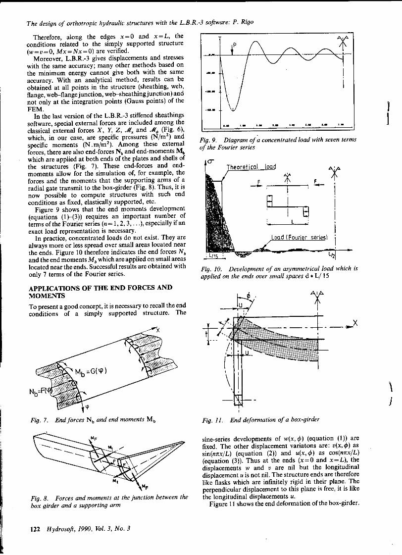
ln the last version of the L.B.R.-3 stiffened sheathings lsoftware, special external forces are included amo~g the 18 'R I.R '.R 4. .. 1.. J.. ..
classical external forces X, Y, Z, vIIx and vII~ (Flg. 6),which, in our case, are specific pressures (N/m2) and . ." .specific moments (N. m/m2). Among these external Flgt.h9. '" Dl~gram .of a concentrated load wlth seven terms
d d M of e rOurler serlesforces, there are also end-forces Nb an en -moments bwhich are applied at bath ends of the plates and shells of 0-the structures (Fig. 7). These end-forces and end- Theoretical load 'moments allow for the simulation of, for example, the ~ ~forces and the moments that the supporting arms of a F /i\ F 1-radial gate transmit to the box-girder (Fig. 8). Thus, it is - ; j; - l,now possible to compute structures with such end "
conditions as fixed, elastically supported, etc. i4-l3 1 Figure 9 shows that the end moments development ; 1
(equations (1}-(3)) requires an important n~mbe~ of . 1 . 1
termsoftheFounersenes(n=1,2,3,...),especlallytfan :. L ~: 1
1 exact load representation is necessary. 1
1 ln practice, concentrated loads do not exist. They are series) '
1always more or less spread over small areas located nearthe ends. Figure 10 therefore indicates the end forces Nb L '
and the end moments Mb which are applied on small areas /2
located near the ends. Successful results are obtained with "'. 10 D 1 t if t " II d h " h .. . rlg. . eve opmen 0 an asymme rlca oa w lC lSonly 7 terms of the Founer senes. 1" d th d II d L/ 15app le on e en s over sma spaces *
APPLICATIONS OF THE END FORCES ANDMOMENTS f-J.,' ~To present a good concept, it is necessary to recall the end --!~ 'l'conditions of a simply supported structure. The
~. Xt -~ t_-- ".
,
11
N ,j
1
Fig. 7. End forces Nb and end moments Mb Fig. Il. End deformation of a box-girder
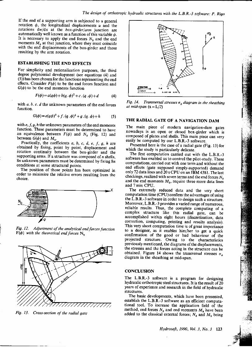
sine-series developments of w(x, </J) (equation (1)) arefixed. The other displacement variatons are: v(x,</J) assin(nnx/L) (equation (2)) and u(x, </J) as cos(nnx/L)(equation (3)). Thus at the ends (x=O and x=L), thedisplacements w and v are nil but the longitudinaldis placement u is not nil. The structure ends are thereforelike flasks which are infini tel y rigid in their plane. Theperpendicular displacement to this plane is free, it is like
Fig. 8. Forces and moments at the junction between the the longitudinal displacements u.box girder and a supporting arm Figure Il shows the end deformation of the box-girder.
122 Hydrosoft, 1990, Vol. 3, No. 3
~
The design of orthotropic hydraulic structures with the L.B.R.-3 software: P. Rigo
If the end of a supporting afIn is subjected to a generalrotation 4J, the longitudinal displacements u and therotations dw/dx at the box-girderjarm junction are a:;
automatically weIl known as a function ofthis variable 4J. II> xIt is necessary to apply the end forces Nb and the endmoments Mb at that junction, where they must coïncidewith the end displacements of the box-girder and thoseresulting by the arm rotation.
EST ABLISHIN G THE END EFFECTS1 For simplicity and rationalization purposes, the third .p
degree polynomial development (see equations (4) and(5)) has been chosen for the functions representing the endeffects. Consider F( 4J) to be the end forces function andf . "Mn.. 1 .G(4J) to be the end moments unctlon E~--+ .
F(4J)=a(q4J)+b(q.4J)2+c.(q.4J)+d (4)Fig.14. Transversal stresses ut/> diagram in the sheathingwith a. b. c. d the unknown parameters of the end forces at mid-span (x=L/2)
function.
G(4»=e(q4J)3+ f.(q.4J)2+g.(q.4J)+h (5) THE RADIAL GATE OF A NAVIGATION DAM
c=with e, f, g, h the unknown parameters of the e.nd moments The main piece of modern navigation-dam gales 1ftfunction. These parameters must be determmed to have nowadays is an open or closed box-girder which îs 4~~an equivalence between F(4J) and Nb (Fig. 12) and composed of plates and shells. This main piece can very ;c~"'"
between G(4J) and Mb' easily be computed by our L.B.R.-3 software.Practically, the coefficients a, b, c, d, e, f, g, h are Presentedhereis the case of a radial gate (Fig. 13) for
obtained by fixing, point by point, displacement and which the study is particularly delicate.rotation continuity between the box-girder and the The first computation carried out with the L.B.R.-3supporting arms. If a structure was composed of n shells, software has enabled us to control the pilot-study. These8n unknown parameters must be determined by fixing 8n computations, carried out with one term and without theconditions at some structural points. end effects (gate supposed simply-supported) demand
The position of those points has been optimized in only 72 data lines and 20 s CPU on an IBM 4381. The lastorder to minimize the relative errors resulting from the checkings, realized with seveD terms and the end forces Nbchoice. and the end moments Mb, require three more data lines
and 7 min CPU.The extremely reduced data and the very short
computation lime (CPU) confirm the advantages of usingthe L.B.R.-3software in order to design such a structure.Moreover, L.B.R.-3 provides a varied range of num~rous,reliable results. Thus, the complete computing of acomplex structure like this radial gale, can beaccomplished within eight hours (discretization, datacorrection, computing, printing and results analysis).
f This very short computation lime is of great importancef' Fig. 12. Adjustment of the analytical endforces function to a designer, as it enables him/her to gel a quickr F(4J) with the theoretical end forces Nb confirmation of the good or bad behaviour of the
projected structure. Owing to the characteristics1 previously mentioned, the diagrams of the displacements,
the stresses and the forces acting in the structure can beobtained. Figure 14 shows the transversal stresses ut/>diagram in the sheathing at mid-span.
CONCLUSION
The L.B.R.-3 software is a program for designinghydraulic orthotropic steel structures. It is the result of 20years of experience and research in the field of hydraulicstructures.
The basic developments, which have been presented,establish the L.B.R.-3 software as an efficient computa-tional tool. To increase the application field of themethod, end forces Nb and end moments Mb have been t;J!
Fig. 13. Cross-section of the radial gale added to the classical external forces; Nb and M b being i;:.
" ."
....:
Hydrosoft, 1990, Vol. 3, No. 3 123
;"è
cc,.."'.
The design of orthotropic hydraulic structures with the L.B.R.-3 software: P. Rigo
applied at bath ends of the shells. So, hydraulic structures Faculté des Sciences Appliquées de l'Université de Liège, in partialwith many boundary conditions can DOW be computed full!lment of the requir.eme~ts for ..the degree of Doctor ofwith the Fourier series. Phllosophy, No. 120, University of Llege, 1989
L B R 3 Il . . . .. 2 Dehousse, N. M. Les bordages raidis en construction hydraulique,. . .- a ~ws °p.tImIzatIOn of .i°cks, .navIgatIon Mémoires du Centre d'Etudes, de Recherche et d'Essais Scientifiques
dams, canal brIdges, tIdal surge bamers, ShIpS such as du Génie Civil (Nouvelle série), 1961, 1, Liègetanker boats, etc. The structure can include 3 types of 3 Dehousse,N. M. and Rigo, P. The design ofcylindricalorthotrop icstiffening reinforcement ribs: stringers, rings and plates and shells, IASS, Madrid Congress, Numerical Method\',cross-bars Vol. 5, Madrid, 1989
. 4 Schnobrich, W. C. DifIerent methods of numerical analysis of shells,
IASS, 1987,945 Gibson, J. E. The development of general multi shell programs usingREFERENCES a micro computer, IASS, Madrid Congress, Numerical Method\', '
Vol. 5, Madrid, 19891 Rigo,P.Applicationsdesdéveloppementsharmoniquesauxcalculsdes 6 Rigo, P. Le calcul des structures cylindriques flottantes, ATMA,
ouvrages hydrauliques métalliques, Collection des Publications de la 89ème Session, Paris, 1989
,
..
[:"~ . c,\:
J
Çij
r~124 Hydrosoft, 1990, Vol. 3, No. 3 1
j
'
Top Related