


Languages
Pages
Legal

2008
First Report of the committee
On
Non-conventional Energy
To
Power Rural Telephony
Department of Telecommunications
Hybrid Wind/Solar Power for Rural
Telephony
Green Solution to Power Problems

2 | P a g e
DOT Committee on Renewable Energy 2008
First Report of the committee
on
Non-conventional Energy To
Power Rural Telephony
November 2008

3 | P a g e
DOT Committee on Renewable Energy 2008
TABLE OF CONTENTS
Sl
No
Topic Page No.
1. DOT Committee on Renewable Energy
5
2. Introduction
6
3. Non Conventional Energy-Solar, Wind & Hybrid Systems
7
4. Appropriate Geographical Region
10
5. Observations on typical BTS Power Requirement in Shared
Sites(USOF)
11
6. System specifications & Design
12
7. System Overview
16
8. Operational difficulties
17
9. Cost Effectiveness
19
10 TRAI Recommendations
20
11. Implementation strategy for renewable energy system in
shared mobile infrastructure sites
21
12. Committee Recommendations
24
Annexures
26-66

4 | P a g e
DOT Committee on Renewable Energy 2008
INDEX OF ANNEXURES
Sl
No.
Topic Page No.
1 Solar Insolation Diagram of India
26
2 Wind Map of India
27
3 Equipment Load measured at various BTS sites
28
4 Rating Calculations
32
5 Single Line Diagram of existing system
34
6 Technical Specifications
Solar Photovoltaic cell
Battery Bank
Charge control unit
Wind turbine generator
35
7 USOF Past initiatives and relevant rulings
51
8 Calculation of DG Operation Hours for Various Options
55
9 Bar Chart
56
10 Financial Calculations – Capex, Payback Period etc
59
11 Layout diagram of USOF Phase-I site for SPV
66
5 | P a g e
DOT Committee on Renewable Energy 2008
DOT COMMITTEE ON RENEWABLE ENERGY
A committee consisting of following officers was constituted
vide DOT reference 32-4/2008-EW dated 11.6.2008 to examine the
use of non-conventional energy power system for rural telephony :
1. Sh. P.K. Panigrahi, Sr. DDG (BW), DOT
2. Smt. Archana Goyal Gulati, Jt. Administrator. (Fin), DOT
3. Sh. U.K. Srivastava, DDG (SAT), TEC
4. Sh. Rajesh Katyal, Unit Chief (C-WET), MNRE, Chennai
Terms of Reference
Feasibility
Appropriate geographical region
System specifications/design
Cost effectiveness
Operational difficulties
Applicability
Pilot projects

6 | P a g e
DOT Committee on Renewable Energy 2008
Introduction:
1.1 Telecommunications has been
recognized as one of the prime
support services needed for rapid
growth and modernization of
various sectors of economy.
However, in achieving a wider
spread of such initiatives in rural
India the dismal state of rural
electrification is a major challenge.
There are villages where the grid
has not even reached, and even
electrified villages do not receive
reliable and quality supply. The
poor power quality substantially
increases the capex and opex of
telecom installations and also leads
to unsatisfactory quality of services.
1.2 The problem of poor electricity
supply is experienced at the telecom
service providers installations as
well as at the customers’ premises.
At the telecom installations, the
problem is tackled by using diesel
generators. These generators,
however, entail transportation and
storage of diesel which is a major
problem in rural/remote area,
Extract from THE MINT, 4-07-08
New Delhi: The boom in demand for
telecom services in India is ringing the till in an
unlikely quarter: makers of diesel-powered electricity generators. As phone firms here expand networks, adding record number of customers every month—in March, more than 10 million new connections were sold, equivalent to the population of Paris or Shanghai—they find they can’t buy enough generators to power their cellular towers. The demand for generator sets, called gensets in short, that can juice up the equipment and electronics at cellular base station towers, is estimated by analysts at more than 200,000 last year and is predicted to expand at between 15% and 20% a year in the years ahead. Telecom towers have radio antennas planted on them, which transmit signals for enabling wireless communication between mobile handsets.
This new demand for gensets, expanding at just around 10% until last year, is driven by expansion of telecom infrastructure in rural areas, where constant and consistent electricity supply is a rarity. “The extensive roll-out of telecom towers in rural and interior areas is the main reason, as power availability is either inadequate or non-existent in these areas,” said Ajay Madan, chief executive (telecom), Essar Telecom Infrastructure Pvt. Ltd (ETIPL). “In 2006, about 55,000 towers were set up and in 2007, the number doubled to 100,000.” In fiscal 2009, as market leaders such as Bharti Airtel Ltd and Reliance Communications Ltd (RCom), vie for new customers, their network expansions are leading them to India’s small towns and villages. Already for Bharti Airtel, India’s No. 1 mobile phone services firm, one in three new customers is from what it calls rural areas.“We are adding almost 3,000 towers every month,” said Manoj Kohli, joint managing director�of� Bharti�Airtel, recently. “That is, 100 a day.” Most of these towers, as also most among the more than 60,000 towers that Indian phone firms and tower firms such as GTL Infrastructure Ltd and ETIPL will set up this financial year, are going to be in rural places.
With around 150,000 telecom towers currently standing in the country, and another 200,000 to be added over the next three-four years, the demand for ancillaries that go with each tower, which include gensets for back-up electric supply, air conditioners and equipment for tower shelter, is seeing significant growth. For instance, GTL, which plans to have almost 25,000 towers by 2011, up from around 4,000 currently, says it will invest 70% of the planned $2 billion (around Rs8,300 crorse) capital outlay in procuring ancillary products such as portable generators and air conditioners. “We already have around 2,800 generators, and by April this year, we plan to procure another 2,100,” Prakash Ranjalkar, chief operating officer (COO) of GTL, had said in a February interview.
7 | P a g e
DOT Committee on Renewable Energy 2008
besides the problem of noise pollution emanating from the
generators. At customers’ premises the electricity supply problem is
partially mitigated by using battery inverters or dc-dc converters.
The battery however remains only partially charged if the electric
supply is too unreliable.
1.3 Decentralised distributed generation technologies based on
renewable energy resources such as solar photo voltaic (SPV)/ Wind
Turbine Generators (WTG) address the above barriers to a large
extent and are therefore considered as emerging alternate power
solutions to power telecommunications net-works.
2. Non-Conventional Energy:
2.1 Solar Energy
2.1.1 In India the annual global solar radiation is about 5 KWh/ sq
m per day with about 2300-3200 sun-shine hours per year. Solar
radiations represent the earth’s most abundant energy source. The
perennial source of solar energy provides unlimited supply, has no
negative impact on the environment. The solar photovoltaic (PV)
modules convert solar radiation from the sun into electrical energy
in the form of direct current (DC). Converting solar energy into
electricity is the answer to the mounting power problems in the
rural areas. Its suitability for decentralized applications and its
environment-friendly nature make it an attractive option to
supplement the energy supply from other sources. 1 KWp of SPV
generates 3.5-4.5 units (KWhr) per day.
2.1.2 If we could install Solar Photovoltaic Cells much of the rural
exchange power needs could be met, adequately cutting down
harmful greenhouse gases.
8 | P a g e
DOT Committee on Renewable Energy 2008
2.2 Wind Energy
Wind energy is another viable option. The Wind Turbine
Generator is designed for optimal operation at wind speed of 10-14
m/s. The Turbine Generator starts at a cut-in speed of 3-3.5 m/s
and generates power at speeds 4.5 m/s and above. In India the
best wind speed is available during monsoon from May to
September and low wind speed during November to March. The
annual national average wind speed considered is 5-6 m/s.
Wherever average wind speed of 4.5 m/s. and above is available it
is also an attractive option to supplement the energy supply. Wind
generators can even be installed on telecom tower at a height of
15-20 mt. with suitable modification in tower design, taking into
account tower strength and EMI & EMC.
1 KW WTG generates around 3 units (KWhr) per day.
2.3 Solar-Wind Hybrid Power System
2.3.1 Hybrid Wind-Solar System for the rural exchanges can make
an ideal alternative in areas where wind velocity of 5-6 m/s is
available. Solar-wind power generations are clear and non-polluting.
Also they complement each other. During the period of bright sun-
light the solar energy is utilized for charging the batteries, creating
enough energy reserve to be drawn during night, while the wind
turbine produce most of the energy during monsoon when solar-
power generation is minimum. Thus the hybrid combination uses
the best of both means and can provide quality, stable power
supply for sustainable development in rural areas.
9 | P a g e
DOT Committee on Renewable Energy 2008
2.3.2 These systems are specifically designed to draw 48 volts DC
power output from the solar cells/ wind turbines and combine them
to charge the storage batteries. The system does require availability
of diesel generator, though for much reduced number of hour’s
operation. It is also designed to give priority to solar and wind
power so that operations of generators can be minimized to the
extent possible.
3. Advantages of Renewable Energy Systems
• Provides un-interrupted power supply to the equipment
• Provide clean, green, reliable, pollution free, low
emission and distributed technology power
• Saves from high-running cost of generator and
increasing diesel cost
• The system gives quality power out-put of 48 volt DC to
charge directly the storage battery or provide direct power
to telecom installations.
• The system can be designed for both off-grid and on-
grid applications.
• Efficient and easy installation, longer life
• Low gestation period
• Low operating cost
10 | P a g e
DOT Committee on Renewable Energy 2008
4. Appropriate geographical region:
4.1 Solar:
In India the annual average solar radiation of 5 KW h/sq m
per day with about 2300-3200 sunshine hours per year is available
in most parts of the country except some pockets in north-east. As
such solar power (SPV) decentralized system can be considered for
the telecommunication network in rural areas in most parts of the
country. (Annexure-1)
4.2 Wind:
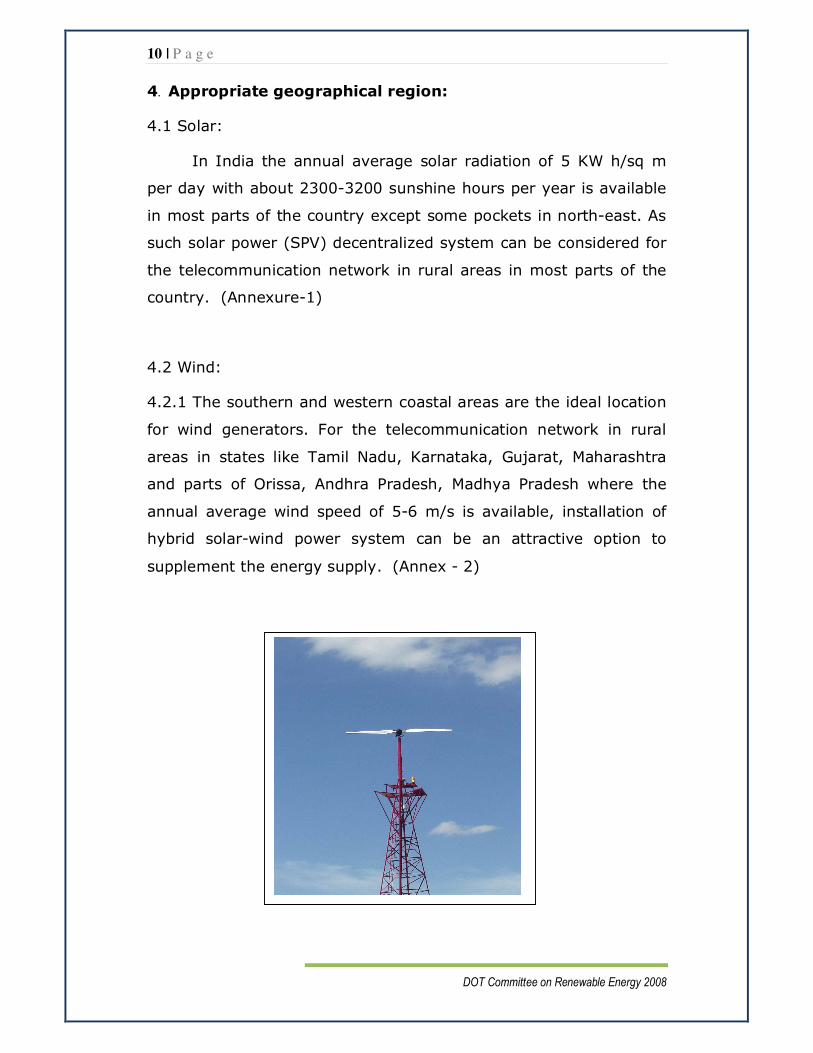
4.2.1 The southern and western coastal areas are the ideal location
for wind generators. For the telecommunication network in rural
areas in states like Tamil Nadu, Karnataka, Gujarat, Maharashtra
and parts of Orissa, Andhra Pradesh, Madhya Pradesh where the
annual average wind speed of 5-6 m/s is available, installation of
hybrid solar-wind power system can be an attractive option to
supplement the energy supply. (Annex - 2)
11 | P a g e
DOT Committee on Renewable Energy 2008
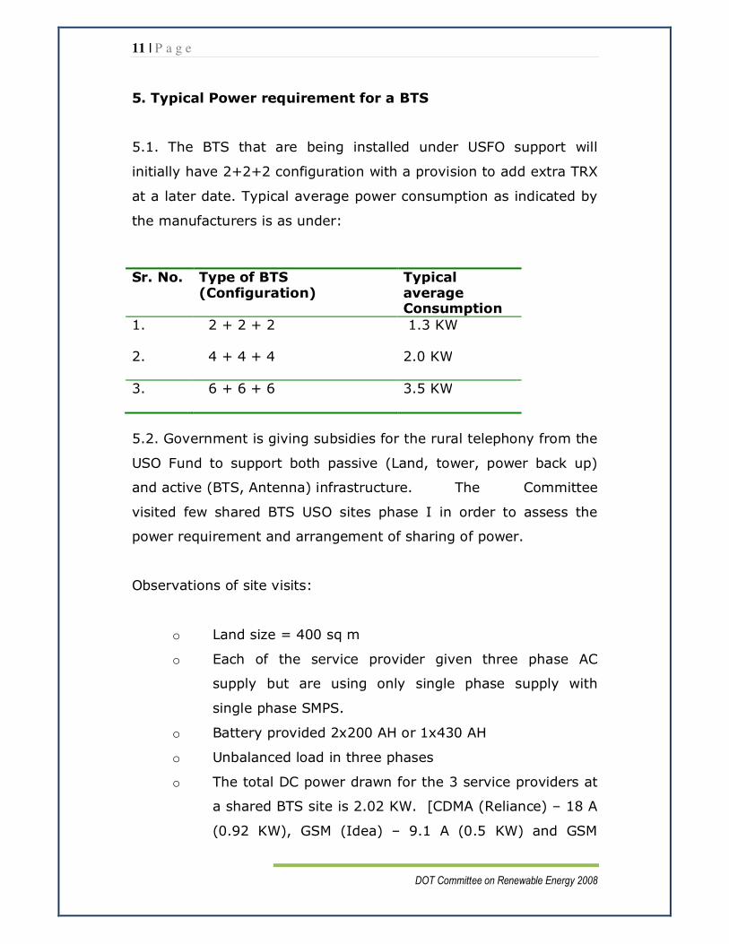
5. Typical Power requirement for a BTS
5.1. The BTS that are being installed under USFO support will
initially have 2+2+2 configuration with a provision to add extra TRX
at a later date. Typical average power consumption as indicated by
the manufacturers is as under:
Sr. No. Type of BTS (Configuration)
Typical average Consumption
1. 2 + 2 + 2
1.3 KW
2. 4 + 4 + 4
2.0 KW
3. 6 + 6 + 6
3.5 KW
5.2. Government is giving subsidies for the rural telephony from the
USO Fund to support both passive (Land, tower, power back up)
and active (BTS, Antenna) infrastructure. The Committee
visited few shared BTS USO sites phase I in order to assess the
power requirement and arrangement of sharing of power.
Observations of site visits:
o Land size = 400 sq m
o Each of the service provider given three phase AC
supply but are using only single phase supply with
single phase SMPS.
o Battery provided 2x200 AH or 1x430 AH
o Unbalanced load in three phases
o The total DC power drawn for the 3 service providers at
a shared BTS site is 2.02 KW. [CDMA (Reliance) – 18 A
(0.92 KW), GSM (Idea) – 9.1 A (0.5 KW) and GSM

12 | P a g e
DOT Committee on Renewable Energy 2008
(Voda phone) – 12.8 A (0.6 KW)]. Details as at
Annexure - 3
o The Engine is operating at 10% load for 24x7 days
where grid supply is not available
6. System specifications/design:
6.1 At present the service providers at a shared BTS site use a
common grid connection and DG set provided by the infrastructure
provider. The power plant and batteries are individually installed by
the service providers. (Annexure-5). The use of renewable energy
systems i.e. SPV and WTG can be efficiently utilized, if they are also
provided centrally like the DG set. This will reduce the overall
system cost and requirement of the BTS site area. The renewable
energy power system proposed assumes centralized arrangement
for power plant and batteries.
6.2 For powering three BTS at one location, a single solar power
(SPV) system would be much more economical as compared to
three separate systems. The system has been designed considering
the power requirement of 2 KW at present and 6 KW in near future
for a shared rural BTS sites (3 service providers) with 1+1 day
autonomy (Annexure 4 & 8). The requirement of solar power (SPV)
is as given under :-
Switch DC
load
Solar panel (SPV)
for Stand alone
system
Solar panel
(SPV) with 2-7
hrs. DG set operation
2 KW 17 KWp 8.5 KWp
3 KW 25 KWp 12 KWp
4 KW 34 KWp 17 KWp
6 KW 50 KWp 25 KWp

13 | P a g e
DOT Committee on Renewable Energy 2008
6.3 The space requirement of Solar PV is 12-13 sq m/ KWp. The
space requirement for accommodating 17 KWp SPV and 25 KWp
SPV is approximately 220 sq mt & 320 sq mt respectively.
• For 2 KW load 17 KWp SPV will work as a stand alone system
with no DG operation required.
• For 4 KW load, the same 17 KWp solar system will work in
hybrid combination with DG set, 4 hrs. operation in a day.
• For 6 KW load, the solar panel needs to be augmented to 25
KWp to work in hybrid combination with DG set, 7 hrs.
operation in a day.
14 | P a g e
DOT Committee on Renewable Energy 2008
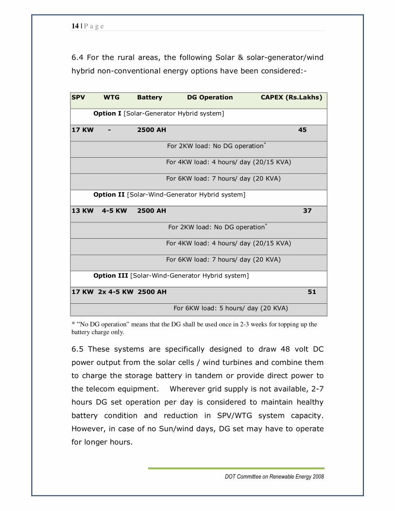
6.4 For the rural areas, the following Solar & solar-generator/wind
hybrid non-conventional energy options have been considered:-
SPV WTG Battery DG Operation CAPEX (Rs.Lakhs)
Option I [Solar-Generator Hybrid system]
17 KW - 2500 AH 45
For 2KW load: No DG operation*
For 4KW load: 4 hours/ day (20/15 KVA)
For 6KW load: 7 hours/ day (20 KVA)
Option II [Solar-Wind-Generator Hybrid system]
13 KW 4-5 KW 2500 AH 37
For 2KW load: No DG operation*
For 4KW load: 4 hours/ day (20/15 KVA)
For 6KW load: 7 hours/ day (20 KVA)
Option III [Solar-Wind-Generator Hybrid system]
17 KW 2x 4-5 KW 2500 AH 51
For 6KW load: 5 hours/ day (20 KVA)
* “No DG operation” means that the DG shall be used once in 2-3 weeks for topping up the battery charge only.
6.5 These systems are specifically designed to draw 48 volt DC
power output from the solar cells / wind turbines and combine them
to charge the storage battery in tandem or provide direct power to
the telecom equipment. Wherever grid supply is not available, 2-7
hours DG set operation per day is considered to maintain healthy
battery condition and reduction in SPV/WTG system capacity.
However, in case of no Sun/wind days, DG set may have to operate
for longer hours.

15 | P a g e
DOT Committee on Renewable Energy 2008
6.6 The system design / specification for solar (SPV) system and
hybrid solar-wind is at Annexure – 4 &5 respectively.
7. Shared BTS rural sites
7.1 In a typical USOF Phase-I shared rural BTS site of 20 x 20 mtr,
having a tower, 15 KVA DG set & 3 BTS shelters only 160 sq mtr
clear space is available (layout at Annexure-11). The electric load
of a shared BTS site at present is 2 KW and is likely to increase
ultimately to 6 KW for which, the 17 /25 KWp SPV required can not
be accommodated. For the USOF Phase-I sites where only 160 sq
mtr space is available, only 10 KWp SPV can be accommodated.
Considering the space constraints in the USOF Phase-I sites in rural
areas, the following Solar & solar-generator/wind hybrid non-
conventional energy options have been considered:-
SPV WTG Battery DG Operation CAPEX(Rs.Lakhs)
Option I [Solar-Generator Hybrid system]
10 KW - 2500 AH 26
For 2KW load: 2 hours/ day (20/15 KVA)
For 4KW load: 6 hours/ day (20/15 KVA)
For 6KW load: 9 hours/ day (20 KVA)
Option II [Solar-Wind-Generator Hybrid system]
10 KW 4-5 KW 2500 AH 29
For 2KW load: 1 hour/ day (20/15 KVA)
For 4KW load: 5 hours/ day (20/15 KVA)
For 6KW load: 8 hours/ day (20 KVA)

16 | P a g e
DOT Committee on Renewable Energy 2008
7.2 In future USOF shared rural BTS sites, if the plot area is
increased to 20x25 mtr , 17 KWp SPV can be accommodated so that
DG operation can be reduced by 4 hrs daily.
8. System overview:
8.1 System configuration
The proposed system uses centralized power plant, battery bank,
SPV and WTG (where feasible). All these are centrally controlled by
a Charge Control Unit(CCU) for optimal powering of systems and
charging of the battery bank. The CCU ensures smooth operation of
the overall powering arrangement without any manual intervention.
Its design will ensure optimal energy transfer from the SPV system
using MPPT (Maximum Power Point Tracking) technique and
automatic switching on/off of DG set on the basis of battery charge
condition. The schematic for this system is placed at Annexure-6.
8.2 Battery
The battery bank has been sized to ensure full utilization of
the renewable energy power generated at the site. As mentioned
earlier, the charging of the battery will take place by automatic
control of DG set operation so as to ensure that the battery is not
unduly discharged.
The poor availability of grid power in the rural areas leaves
the battery bank in partial state of charge. This reduces the life of
battery considerably. One option to circumvent this problem is to
use flooded batteries. However maintenance and space
requirements of such batteries prohibit their use. Another option is
to use Tubular GEL VRLA batteries as they provide better
performance under the partial state of charge.

17 | P a g e
DOT Committee on Renewable Energy 2008
Additional advantages of Tubular GEL VRLA battery over VRLA AGM
(flat plate):-
• Better thermal management because of more electrolyte
• Cyclic life is 30% to 40% higher than AGM batteries. (2100
cycles in Tubular GEL as compared to 1400 cycles in AGM)
• Self discharge is lower than AGM batteries and can be stored
upto one year against 6 months as in AGM • Better performance at high temperature
• Slow rate of discharge performance suits rural applications.
Therefore Tubular GEL VRLA batteries are recommended for this
application.
9. Operational Difficulties:
9.1 There is no operational difficulty as such in a solar (SPV) system
and hybrid solar wind system. Only the solar panels need to be
cleaned with water at regular intervals. In case of a Wind Turbine
Generator, the power generation depends on the wind velocity.
Thus restricted to locations where the annual average wind velocity
is 4.5 m/s or higher. For the wind mills annual preventive
maintenance is required for optimal efficiency.
18 | P a g e
DOT Committee on Renewable Energy 2008
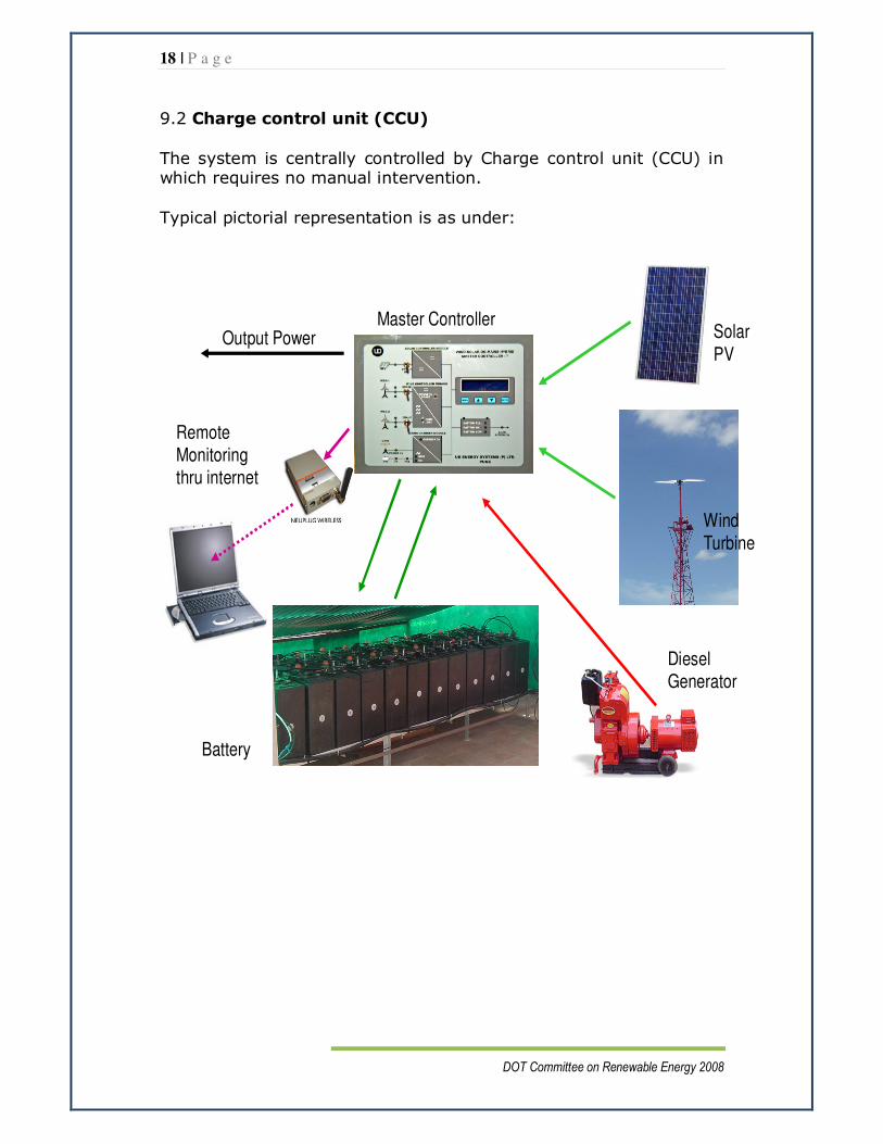
9.2 Charge control unit (CCU)
The system is centrally controlled by Charge control unit (CCU) in which requires no manual intervention.
Typical pictorial representation is as under:
Diesel Generator
Battery
Wind Turbine
Solar
PV
Master Controller
Remote Monitoring thru internet
Output Power

19 | P a g e
DOT Committee on Renewable Energy 2008
10. Cost effectiveness:
10.1 The CAPEX of the solar / hybrid solar-wind systems ranging
from 10KW to 17KW comes to around 26-51 lakhs after considering
the 80 percent accelerated depreciation benefit given by the
Government of India(owing to which there will be reduction of about
25% in capital cost).
10.2 The generator usage varies with the load as discussed in the
preceding paragraphs.
10.3 The proposed solar/hybrid solar-wind systems give 48 volt DC
power output to charge the storage battery and provide direct DC
power to the telecom equipment. Hence the individual SMPS,
battery charger, battery banks provided by the service providers at
present under active infrastructure component in USOF schemes are
not required. Apart from that there will be cost savings on account
of nil/lesser hours of DG Set operation.
10.4 The cost comparison on running the equipment entirely on DG
set 24x7 for 365 days (case of an off grid site) and the different
combinations of solar/wind-solar system with various loads is placed
at Annex.-10. The systems are cost effective from first year
itself/within the initial few years.
10.5 Considering the annual saving of fuel, the pay back period for
various systems ranges from around 4-9 years (Annex.- 10)
depending upon the capacity of the SPV/hybrid installation and the
load.
10.6 Given the heavy initial CAPEX and long pay back periods there
is therefore a case for subsidy support.

20 | P a g e
DOT Committee on Renewable Energy 2008
11. TRAI Recommendations
Telecom Regulatory Authority India in its recommendations
on infrastructure sharing para 5.3.3.1 recommended as under:-
(i) Department of Non-Conventional Energy Resources may be
approached by DoT to evolve a pro-active policy framework to
encourage use of environment friendly non-conventional
energy sources. Some of the specific measures in this regard
are given below:-
a) To device a policy to promote the use of solar power and
alternative fuel specifically for Telecom sector.
b) To provide Telecom specific Advisories on available
equipments, costs, sources for procurement etc. to
service providers.
c) To maximize subsidies for Telecom operators
considering potential of high use of such devices in
telecom sector.
d) To examine possibilities of use of other non-
conventional environment friendly energy sources.
ii) DOT may evolve a scheme of subsidy per site to service
providers and incentives for using non-conventional
energy sources.
21 | P a g e
DOT Committee on Renewable Energy 2008
12. Implementation strategy for renewable energy system
in shared mobile infrastructure sites.
12.1 The USOF has taken few initiatives in the past regarding
introduction of renewable energy. The details of such initiatives,
rulings etc as provided by Jt. Administrator(F), USOF, are placed at
Annexure-7.
12.2 The committee has been apprised that IPs and USPs have
been repeatedly approaching USOF and MNRE for subsidy support
for installation of renewable energy systems to power telecom sites
in rural and remote parts of the country.
12.3 USOF support for use of renewable energy can be given in
two possible ways:
12.3.1 Pilot Projects: The committee recommends that a few
USOF Phase-I sites may be selected to demonstrate and evaluate
the efficacy and cost effectiveness of various renewable energy
options. Appropriate combinations of solar and wind energy
equipment would be installed at suitable sites as per approved
specifications. The funding mechanism may be finalized by
incorporating cost sharing by MNRE, USOF, and TSP.
12.3.2 The committee notes that BSNL is the IP in bulk of the USOF
phase-I sites (78%), therefore its sites would offer the required
diversity of geographical locations. The committee recommends
that BSNL sites may be selected for carrying out the pilot projects.
The geographical location of the site may be so chosen as to ensure
proper utilization of SPV & WTG systems. The pilot projects shall be
22 | P a g e
DOT Committee on Renewable Energy 2008
jointly monitored by TEC, Electrical wing of DOT, USOF, and MNRE.
The data from the pilots would help in fine-tuning technical
specifications leading to development of Generic Requirements (GR)
by TEC, and working out subsidy model for hybrid power solutions
for telecom installations.
12.3.3 Shared Mobile Infrastructure Sites: USOF may evolve a
separate subsidy component for various hybrid energy solutions in
sites coming up in future mobile infrastructure schemes. Given the
fact that about 11000 odd shared mobile sites are slated to come
up in villages that are even more remote and small as compared to
the location of USOF’s Mobile Infrastructure Phase I sites, it may be
prudent to presume that the availability of power would be an even
greater constraint for these new sites. It is envisaged that the
subsidy would be offered as an incentive to use renewable energy
instead of a second DG set in an off grid site or even to cut down on
hours of operation of the DG set. It is expected that this would
make the USOF sites less dependant on the relatively costly and
polluting option of using diesel in locations where grid power supply
in unavailable/erratic/insufficient.
12.3.4 A system may be considered whereby in Phase II, the IPs
and USPs concerned would make a joint decision within few months
of signing of the agreement (coinciding with site finalization) as to
whether or not to opt for renewable energy usage for a particular
site and which hybrid model they wish to install. Upon exercising
this option, they would then be eligible for an additional subsidy
based on the particular hybrid model they choose. The detailed
subsidy model and calculations would be worked out by USOF,
taking into consideration capital recovery as well as savings on
account of fuel and re-locatable infrastructural components (for Part

23 | P a g e
DOT Committee on Renewable Energy 2008
B TSPs). It is suggested that subsidy be disbursed only upon
successful commissioning of the system and after due verification.
Apart from saving the operators the huge cost of supply and
consumption of diesel in remote locations, switching to renewable
energy would provide for sustained rural telecom services to target
beneficiaries in a cost effective manner while also cutting down on
harmful carbon emissions.
12.3.5 The above mentioned USOF support for use of renewable
energy by way of pilot projects and future USOF mobile
infrastructure sites, would serve to encourage greater utilization of
solar-wind hybrids and demonstrate their cost effectiveness in the
long run. It is felt that these initiatives under the aegis of DOT
through USOF, carried out in coordination with MNRE, would have a
significant impact on the rural telecom scenario and the use of clean
energy in telecommunications would receive a much needed fillip.

24 | P a g e
DOT Committee on Renewable Energy 2008
13. Recommendations:
I. The non-conventional energy-solar /solar-wind hybrid
power system is found to be technically feasible and cost
effective in long run. Its environment-friendly nature
make it an attractive option to supplement the energy
supply in rural areas. DOT to make a policy to promote
the use of environment-friendly solar / solar-wind
hybrid non-conventional energy power system for
telecom network in rural and remote areas.
II. The present arrangement of individual installation of power
plant and battery by service providers will have to be
changed to centralized DC power arrangement by the
infrastructure provider to ensure optimal use of the BTS
site area for installation of SPV and WTG systems. Further,
augmentation of the BTS plot size from the present
400 sq mtr to 500 sq mtr may be considered for
facilitation of SPV system of 17 KWp which will result
in reduction of DG set operation, atleast by 4 hrs daily.
III. To prove the technical and financial viabilities for solar /
solar-wind hybrid renewable energy systems for rural and
remote telecom sites, DOT should fund, through USOF,
pilot projects in USOF shared infrastructure sites.
The projects shall be undertaken in coordination with MNRE
who would provide technical and financial support as well.
a) 1 project of Solar (SPV) power system in each state
except north-east region.
b) 2 projects of solar-wind hybrid system in 4 states –
Maharashtra, Tamil Nadu, Gujarat, Karnataka and 1

25 | P a g e
DOT Committee on Renewable Energy 2008
each in Orissa, Andhra Pradesh and Madhya Pradesh
where the annual average wind speed is 5-6 m/s or
higher.
IV. The initial capital cost being high, there is a hesitation to
go in for renewable energy power option. DOT to
encourage the telecom service providers by giving
separate subsidies / incentives for using non-
conventional energy sources in rural and remote
areas. The service providers can have the additional
benefit of carbon credit as well.
V. To further encourage the wide spread adoption of
renewable energy in telecom installations in rural and
remote areas, appropriate subsidy scheme should be
made available to all telecom operators going in for
renewable energy installations in USOF’s future
mobile infrastructure schemes.
Unit Chief (C-WET) DDG (SAT) Jt. Admntr. (Fin)
MNRE, Chennai TEC DOT
Sr. DDG (BW)
DOT

26 | P a g e
DOT Committee on Renewable Energy 2008
ANNEXURE 1
Solar Insolation diagram of India

27 | P a g e
DOT Committee on Renewable Energy 2008
ANNEXURE 2
Wind Map Of India
28 | P a g e
DOT Committee on Renewable Energy 2008
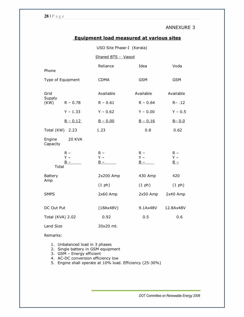
ANNEXURE 3
Equipment load measured at various sites
USO Site Phase-I (Kerala)
Shared BTS - Vasod
Reliance Idea Voda
Phone
Type of Equipment CDMA GSM GSM
Grid Available Available Available
Supply (KW) R – 0.78 R – 0.61 R – 0.64 R– .12
Y – 1.33 Y – 0.62 Y – 0.00 Y – 0.5
B – 0.12 B – 0.00 B – 0.16 B– 0.0
Total (KW) 2.23 1.23 0.8 0.62
Engine 20 KVA
Capacity R – R – R – R –
Y – Y – Y – Y –
B – B – B – B – Total
Battery 2x200 Amp 430 Amp 420
Amp
(1 ph) (1 ph) (1 ph)
SMPS 2x60 Amp 2x50 Amp 2x40 Amp
DC Out Put (18Ax48V) 9.1Ax48V 12.8Ax48V
Total (KVA) 2.02 0.92 0.5 0.6
Land Size 20x20 mt.
Remarks:
1. Unbalanced load in 3 phases
2. Single battery in GSM equipment 3. GSM – Energy efficient
4. AC-DC conversion efficiency low
5. Engine shall operate at 10% load. Efficiency (25-30%)

29 | P a g e
DOT Committee on Renewable Energy 2008
USO Site Phase-I (Kerala)
Shared BTS - Nalumuku
Reliance Idea Vodafone Type of Equipment CDMA GSM GSM
Grid Not Available Not Available Not Available Supply
R – R – R – R –
Y – Y – Y – Y – B – B – B – B –
Total
Engine Capacity 20 KVA
R – 1.5 KW R – 2.5 Amp R – 1.5 Amp R–1.5Amp Y – 0.2 KW Y – Y – Y –
B – 0.6 KW B – B – 0.06 A B – 0.07 A
Total (KW) 2.3 1 0.6 0.6
Battery 2x200 Amp 430 Amp 420 Amp
SMPS 2x60 Amp 2x50 Amp 2x40 Amp
(1 ph) (1 ph) (1 ph)
DC Out Put (19Ax48V) 9.4Ax48V 10Ax48V
0.91 (0.45) (0.48)
Total (KVA): 2 ≈ 1 ≈ 0.5 ≈ 0.5
Land size : 20x20 mt
Remarks:
1. Unbalanced load on generator
2. Engine operating at 10% load. Efficiency 25-30%

30 | P a g e
DOT Committee on Renewable Energy 2008
USO Site Phase-I ( Karnataka)
Shared BTS - Hunsenahawli
Reliance Voda phone BSNL
Type of Equipment CDMA GSM GSM
Grid Not Available Not Available Not Available
Supply
R – R – R – R – Y – Y – Y – Y –
B – B – B – B – Total KW -
Engine
Capacity 20 KVA (Working) R – 9A R – R – R –
Y – 0 Y – Y – Y –
B – 0 B – B – B – Total (KW) 2.07
Battery 2x200 AH 1x430 AH 2x400 AH
(48 V) (48 V) (48 V)
Single Single
SMPS 3x50 A 2x60 A 2x50 A
(1 ph) (1 ph) (3 ph) Using single ph
DC Out Put 12.4 Ax48 V
Total (KVA): 0.6
Land Size : 25x16 mt.
Remarks:
1. Unbalanced load on generator 2. Engine operating at 10% load. Efficiency 25-30%
3. BSNL installed 3 ph SMPS using single ph.
31 | P a g e
DOT Committee on Renewable Energy 2008
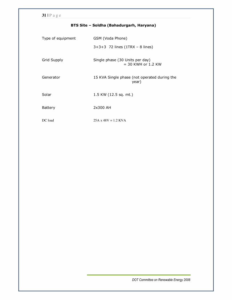
BTS Site – Soldha (Bahadurgarh, Haryana)
Type of equipment GSM (Voda Phone)
3+3+3 72 lines (1TRX – 8 lines)
Grid Supply Single phase (30 Units per day)
= 30 KWH or 1.2 KW
Generator 15 KVA Single phase (not operated during the
year)
Solar 1.5 KW (12.5 sq. mt.)
Battery 2x300 AH
DC load 25A x 48V = 1.2 KVA

32 | P a g e
DOT Committee on Renewable Energy 2008
ANNEXURE 4
Rating Calculations
I. Load Power Quantity Total
Power
Duration Energy
Watt No. Watt Hour Watt-
Hour
Amp. Hr
(48 Volt)
1 Exchange
equipment
2000 1 2000 24 48000 1000.00
2 CFL 11 1 11 2 22 0.46
3 Aviation
light
100 1 100 12 1200 25.00
4 Compound
light
40 2 80 12 960 20.00
2191 50182 1045
One module :12 v so a string of 4 modules required to produce 48 v
A 125 Wp module can generate 40AH (8A x 5Hrs) of energy
Battery requirement= AH/.85x.95x.95 = 1363 AH
(85%battery efficiency, 95% CCU, 5% dust etc)
Total no. of strings of 125 Wp modules required 34
Total Capacity of SPV = 34x4x125W = 17000 W i.e 17 KW
Battery reqd (Considering 1+1 days autonomy) 2500 AH
SPV calculations- BTS Sites
II. Load Power Quantity Total
Power
Duration Energy
Watt No. Watt Hour Watt-
Hour
Amp. Hr
(48 Volt)
1 Exchange
equipment
3000 1 3000 24 72000 1500.00
2 CFL 11 1 11 2 22 0.46
3 Aviation
light
100 1 100 12 1200 25.00
4 Compound
light
40 2 80 12 960 20.00
3191 74182 1545
Battery requirement= AH/.85x.95x.95 = 2015 AH
(85%battery efficiency, 95% CCU, 5% dust etc)
Total no. of strings of 125 Wp modules required 50
Total Capacity of SPV = 50x4x125W = 25000 W
Battery reqd (Considering 1+1 days autonomy) 4000 AH
33 | P a g e
DOT Committee on Renewable Energy 2008
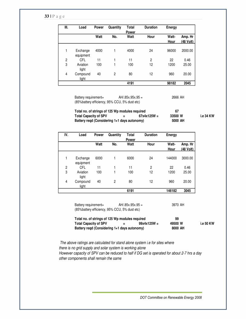
III. Load Power Quantity Total
Power
Duration Energy
Watt No. Watt Hour Watt-
Hour
Amp. Hr
(48 Volt)
1 Exchange
equipment
4000 1 4000 24 96000 2000.00
2 CFL 11 1 11 2 22 0.46
3 Aviation
light
100 1 100 12 1200 25.00
4 Compound
light
40 2 80 12 960 20.00
4191 98182 2045
Battery requirement= AH/.85x.95x.95 = 2666 AH
(85%battery efficiency, 95% CCU, 5% dust etc)
Total no. of strings of 125 Wp modules required 67
Total Capacity of SPV = 67x4x125W = 33500 W i.e 34 KW
Battery reqd (Considering 1+1 days autonomy) 5000 AH
IV. Load Power Quantity Total
Power
Duration Energy
Watt No. Watt Hour Watt-
Hour
Amp. Hr
(48 Volt)
1 Exchange
equipment
6000 1 6000 24 144000 3000.00
2 CFL 11 1 11 2 22 0.46
3 Aviation
light
100 1 100 12 1200 25.00
4 Compound
light
40 2 80 12 960 20.00
6191 146182 3045
Battery requirement= AH/.85x.95x.95 = 3970 AH
(85%battery efficiency, 95% CCU, 5% dust etc)
Total no. of strings of 125 Wp modules required 99
Total Capacity of SPV = 99x4x125W = 49500 W i.e 50 KW
Battery reqd (Considering 1+1 days autonomy) 8000 AH
The above ratings are calculated for stand alone system i.e for sites where
there is no grid supply and solar system is working alone
However capacity of SPV can be reduced to half if DG set is operated for about 2-7 hrs a day
other components shall remain the same

34 | P a g e
DOT Committee on Renewable Energy 2008
ANNEXURE 5
Single Line Diagram of Existing System
Grid
Gen
3-Ø
20 KVA, 3-Ø
Service Provider 1
48 V DC bus
LT panel- Surge arrestors
SMPS BTS equipment
Battery bank
48 V DC bus
LT panel- Surge arrestors
SMPS BTS equipment
Battery bank
48 V DC bus
LT panel- Surge arrestors
SMPS BTS equipment
Battery
bank
Service Provider 2
Service Provider 3

35 | P a g e
DOT Committee on Renewable Energy 2008
ANNEXURE 6
Technical Specifications
Introduction This document specifies the technical requirements for powering arrangement for shared BTS sites in rural areas of the country. It is envisaged to employ renewable energy sources i.e. Solar Power and Wind Power in the powering scheme, depending upon the availability of power source. In effect, the powering system shall comprise of solar power, wind power (where feasible), grid supply, and diesel generators of suitable capacities. A typical schematic for the powering arrangement is shown in the fig. 1 below:
* Rectifier can be outside CCU module
Fig. - Schematic for powering arrangement at shared rural BTS sites.
Grid
Gen
3-Ø
15 KVA, 1-Ø
Battery
bank
48 V DC Automatic
Phase selector
SPV
DC bus
Rectifier*
WTG
SPV charge controller
WTG charge controller
CCU
Service Provider 1
Service Provider 2
Service Provider 3
36 | P a g e
DOT Committee on Renewable Energy 2008
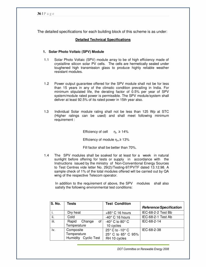
The detailed specifications for each building block of this scheme is as under:
Detailed Technical Specifications
1. Solar Photo Voltaic (SPV) Module
1.1 Solar Photo Voltaic (SPV) module array to be of high efficiency made of crystalline silicon solar PV cells. The cells are hermetically sealed under toughened high transmission glass to produce highly reliable weather resistant modules.
1.2 Power output guarantee offered for the SPV module shall not be for less than 15 years in any of the climatic condition prevailing in India. For minimum stipulated life, the derating factor of 0.5% per year of SPV system/module rated power is permissible. The SPV module/system shall deliver at least 92.5% of its rated power in 15th year also.
1.3 Individual Solar module rating shall not be less than 125 Wp at STC (Higher ratings can be used) and shall meet following minimum requirement :
Efficiency of cell ηc ≥ 14%
Efficiency of module ηm ≥ 13%
Fill factor shall be better than 70%.
1.4 The SPV modules shall be soaked for at least for a week in natural sunlight before offering for tests or supply in accordance with the Instructions issued by the ministry of Non-Conventional Energy Sources to Test Centres vide letter No. 29(2)/Testing-97/PVTF dated 13.12.98. A sample check of 1% of the total modules offered will be carried out by QA wing of the respective Telecom operator.
In addition to the requirement of above, the SPV modules shall also satisfy the following environmental test conditions:
S. No. Tests Test Condition Reference/Specification
i. Dry heat +85° C 16 hours IEC-68-2-2 Test Bb
ii. Cold -40° C 16 hours IEC-68-2-1 Test Ab
iii. Rapid Change of Temperature
-40° C to 80° C 10 cycles
IEC-68-2-14
iv. Composite Temperature Humidity Cyclic Test
25° C to -10° C
25° C to 65° C 95% RH 10 cycles
IEC-68-2-38

37 | P a g e
DOT Committee on Renewable Energy 2008
v. Rain 2 Hours IS 9000 (PART 16)
vi. Heavy dust/sand storm
- Clause 16.0 of QM- 333
vii. Wind speed 200Kms/hour - viii. Hail Storm Hails of 25mm dia
size at 23m/Sec velocity shall not cause physical damage to any part of the solar array or associated structures.
-
ix. Bending & twisting module shall withstand a displacement at one corner by 20 mm/metre measured along with the shortest edge without open or short circuit within the module or suffer low resistance between terminals to frame.
x. Insulation test for module
As per IEC : 61215 IEC : 61215
xi. Hot-spot endurance test
As per IEC : 61215 IEC : 61215
xii. Robustness of termination test
As per IEC : 61215
IEC : 61215
xiii. Wet leakage current test
As per IEC : 61215
IEC : 61215
xiv. Bypass diode thermal test
As per IEC : 61215
IEC : 61215
1.5 Insolation- Main insolation at any panel kept at optimum tilt at place where the
solar panel is to be used shall be 4.5 Kw hour per m2 per day.
1.6 I-V curve peak (maximum) power output: The SPV module shall deliver minimum 12.5 watt at maximum power point of I-V curve at standard condition of 100 mw/cm2 solar intensity at 25 degree C. I-V curve of each PV module with Sl. Nos. shall be submitted along with following details:
• Maximum Power, Pmax
• Open Circuit Voltage, Voc
• Short Circuit Current, Isc
• Voltage at maximum power, Vmp
• Current at maximum power, Imp
• Efficiency of cell ηc
• Efficiency of module ηm

38 | P a g e
DOT Committee on Renewable Energy 2008
1.7 Solar PV module shall conform to following mechanical requirement
• Toughened high transitivity front glass
• Anodized Aluminum frame
• Ethyl Vinyl Acetate (EVA) encapsulated
• Tedlar/Polyester trilaminate back surface
• ABS plastic terminal box for the module output termination with gasket to prevent moisture
• Resistant to water, abrasion, hail impact, humidity & other environmental effects for worst situation at site. Solar PV module shall have proven performance track record in Indian Climatic conditions
• Permissible cell area per watt is between 60 cm2 and 100 cm2. All the cells in the module shall be identical of regular shape. Considering the application and geographical location of India, the number of cells in the series in a module shall be 36.
• Short circuit current shall not be more than 110 percent of Imp.
• Voltage at peak power point: 17.0 V (min).
• Voltage derating not more than 0.5% per degree C above 25 degree C cell temperature.
• The SPV modules being used for Telecom supply, need to be characterized at NPL (National Physical Laboratory) or any other recognised test laboratory for each type of cells used and manufacturer will give the spread in of silicon cells which are used.
1.8 Module Mounting Structure
1.8.1 Structure shall be designed for simple mechanical and electrical installation on roof top or On the ground at an angle of tilt with horizontal, in accordance with the latitude of the place of installation.
1.8.2 It shall support SPV modules at given orientation, absorb and transfer the
mechanical loads to the ground properly.
1.8.3 The structure shall be hot dip Galvanized & shall have anti corrosive paint.
1.8.4 The steel for the mounting structure shall be as per IS 2062: 1992 and mounting structure galvanisation shall be in compliance of IS 4759 (latest issue).
1.8.5 The mounting arrangement shall be suitable for column mounting or flat surface, as desired by the ordering authority.
1.8.6 The Mounting structure shall be easily transportable and designed to
withstand the wind speed of 200KM/hour. Design calculation shall be furnished to show that the proposed structure will withstand the wind speed of

39 | P a g e
DOT Committee on Renewable Energy 2008
200 Km/hr. The design for the mounting structure shall have the certification from a recognised Lab/Institution for the purpose.
1.8.7 Provision for directional and angular adjustment shall be made to ensure the optimum utilisation of incident sunlight.
1.8.8 The design/drawings of the mounting structure shall be supplied along with the module to the purchaser.
1.8.9 The mounting structure shall be suitably designed to withstand the weight of the panel/array.
1.8.10 The exact mounting mechanism shall have to be decided upon and specified by the ordering authority, as per the actual requirement at the site of installation, and the same shall be mentioned in the purchase order.
1.8.11 The array structure shall be so designed that it will occupy minimum space without sacrificing the output of SPV panels.
1.8.12 Structure shall have suitable anti theft measures to prevent easy removal of Solar Modules.
1.9 Array Junction Box
1.9.1 The junction box shall be dust, vermin & Water proof and made of FRP/Thermoplastic with IP65 protection.
1.9.2 The terminals shall be connected to copper bus bar arrangement of proper sizes
1.9.3 The junction box shall have suitable cable entry points fitted with cable glands of appropriate sizes for both incoming and outgoing cables.
1.9.4 Suitable markings shall be provided on the bus bar for easy identification and cable ferrules shall befitted at the cable termination points for identification.
1.9.5 The rating of junction box shall be suitable with adequate safety factor to interconnect solar PV array
1.9.6 Metal oxide arrestors shall be provided inside the array junction boxes.
2. Battery Bank :
2.1 The battery shall be 48V (24 cell)) VRLA type (deep-cyclic), suitable for SPV application i.e. slow rate of charge and discharge conforming preferably to GR/BAT-03/01 MAR 2006 Tubular VRLA batteries based on GEL technology with amendment if any or TEC GR No. GR/BAT-01/03 MAR 2004 with amendments if any for VRLA flat plate technology.
2.2 The capacity of the battery shall be so designed so as to supply the
ultimate load during the non-sunlight hours i.e. during the night and also during the cloudy weather (Number of sunless days at a stretch as specified by the ordering authority) or when both SPV power and AC mains are not available (and also wind power wherever asked for) with

40 | P a g e
DOT Committee on Renewable Energy 2008
80% reserved power in fully charged condition and shall be floated across the SPV panel or SMPS and load through charge controller.
2.3 The nominal voltage of the Battery shall be 48V. However, the actual capacity of the battery in terms of Ampere-hour shall be indicated by the ordering authority.
2.4 The battery shall deliver at 120% of its rated capacity at low rate of discharge between C/20 and C/120. At discharge rate of C/120 or slower, the battery shall deliver at least 150% of its rated capacity.
3. Charge controller unit :
Charge controller unit shall manage power supply employing grid,
SPV, Wind Power, and diesel generator power. It shall provide for the necessary DC power supply to the load and battery and also protect battery bank from over charge, deep discharge, reverse polarity and short circuit, thereby ensuring that the electrical characteristics are met for optimum performance and reliability. It monitors all the functions of SPV power source and SMPS (some on charge controller along with SMPS and all other on the SMPS). It provides for termination for output of the SPV array, output of wind power, output of the SMPS (through a switch), load and battery. It shall house all the necessary alarms, monitoring and control circuits. It shall also provide for the mounting of the lightning and surge protection devices (SPV side on the charge controller itself, while SMPS side lightning and surge protective devices on the SMPS.
3.1 Charge Control Unit/Control Electronics: The Control system should
automatically manage the system operation which include: 3.1.1 Integrated solar, grid, wind, and diesel generator charge regulator.
• In case of availability of Solar/ wind Power, priority shall be given to renewable power over grid/DG.
• With mains being available (Grid Connected System), controller shall decide whether grid is to be utilized depending on State of Charge of the Battery Bank and availability of Solar/wind Power.
• The system shall intelligently do generator exercising at a pre decided interval to prevent seizing up
3.1.2 Battery charging & battery management
• Controller shall have Advance battery management with PWM regulation to keep the battery bank fully charged without over charging / Deep discharging it
• Controller shall have intelligent decision making for regulating the Battery Charging process (Boost, Float, Absorption, Equalization)
3.1.3 Self consumption: Solar regulator shall be microcontroller based with low
energy consumption. The regulator supply current shall not be more that 15 milliamperes.
41 | P a g e
DOT Committee on Renewable Energy 2008
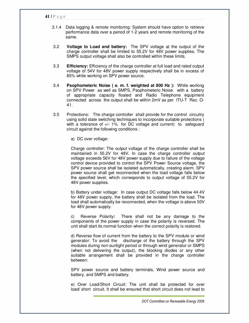
3.1.4 Data logging & remote monitoring: System should have option to retrieve performance data over a period of 1-2 years and remote monitoring of the same.
3.2 Voltage to Load and battery: The SPV voltage at the output of the
charge controller shall be limited to 55.2V for 48V power supplies. The SMPS output voltage shall also be controlled within these limits.
3.3 Efficiency: Efficiency of the charge controller at full load and rated output
voltage of 54V for 48V power supply respectively shall be in excess of 85% while working on SPV power source.
3.4 Psophometeric Noise ( e. m. f. weighted at 800 Hz ): While working
on SPV Power as well as SMPS, Psophometeric Noise with a battery of appropriate capacity floated and Radio Telephone equipment connected across the output shall be within 2mV as per ITU-T Rec. O-41.
3.5 Protections: The charge controller shall provide for the control circuitry
using solid state switching techniques to incorporate suitable protections ( with a tolerance of +/- 1% for DC voltage and current) to safeguard circuit against the following conditions :
a) DC over voltage:
Charge controller: The output voltage of the charge controller shall be maintained in 55.2V for 48V. In case the charge controller output voltage exceeds 56V for 48V power supply due to failure of the voltage control device provided to control the SPV Power Source voltage, the SPV power source shall be isolated automatically, creating alarm. SPV power source shall get reconnected when the load voltage falls below the specified level, which corresponds to output voltage of 55.2V for 48V power supplies.
b) Battery under voltage: In case output DC voltage falls below 44.4V for 48V power supply, the battery shall be isolated from the load. The load shall automatically be reconnected, when the voltage is above 50V for 48V power supply.
c) Reverse Polarity: There shall not be any damage to the components of the power supply in case the polarity is reversed. The unit shall start its normal function when the correct polarity is restored.
d) Reverse flow of current from the battery to the SPV module or wind generator: To avoid the discharge of the battery through the SPV modules during non-sunlight period or through wind generator or SMPS (when not delivering the output), the blocking diodes or any other suitable arrangement shall be provided in the charge controller between: SPV power source and battery terminals, Wind power source and battery, and SMPS and battery. e) Over Load/Short Circuit: The unit shall be protected for over load/ short circuit. It shall be ensured that short circuit does not lead to

42 | P a g e
DOT Committee on Renewable Energy 2008
any fire hazard.
f) Fuse/ circuit Breakers with current limiting devices : Suitably fault rated fuses or circuit breakers with current limiting devices shall be provided for the following :
i. Live AC input line ii. Negative DC output iii. Against failure of control sensing circuit.
Note : 1. Use of mechanical switching devices such as relays etc. is not permitted in the control circuit. MCBs are, however, permitted for short circuit protection only.
2. Two fuses (minimum) of each type shall be provided with each unit. These fuses shall be kept inside the unit in an enclosure.
3.6 Monitoring Alarms and Indicating Lamps : Visual indications/display
shall be provided by means of bright LCDs. Different colour display for different modes shall also be provided.
3.6.1 Functional Indications: The following indications shall be provided to
indicate mode in which the unit is functioning. The functional indications of FR/FC modules and DSCA shall be on FR/FC and DSCA of the SMPS also :
a. AC Mains available - Green (on charge controller, FR/FC module and DSCA) b. Battery Charging by SMPS - Amber c. Battery Charging by SPV Power - Yellow
d. Load on battery - Blue e. Battery Charging by Wind Power - Yellow
Alarms Indications on charge controller:
1. SPV Output Voltage Low. 2. SPV Output Voltage High 3. Battery Low 4. Battery reverse polarity 5. Over load 6. SMPS fail – SMPS fails to deliver power due to any reason
7. Equipment Circuit Breaker Trip (if used) 8. SPV Output Voltage Low. 9. SPV Output Voltage High
Display of System data: following shall be displayed
• Battery bank voltage
• Charging current
• Load current
• Total energy generated
• Total energy utilized
• Maximum battery voltage since midnight
• Wind power voltage

43 | P a g e
DOT Committee on Renewable Energy 2008
• Minimum battery voltage since midnight
• Time of day when battery bank was fully charged
• Solar Panel Voltage (Open Circuit)
• System fault indication
• Performance data for last 1-2 years.
3.6.2 The SMPS shall be housed in 19” rack only. The Distribution Switching Control and Alarm (DSCA) of the SMPS may be mounted in the upper part of the rack above the FR-FC modules, while FR-FC modules shall be mounted in the remaining rack. The matching of the SPV Power source, wind power output and SMPS output shall be ensured by the charge controller.
3.6.3 SMPS shall be based on Switch Mode Power Supply (SMPS) Technique using switching frequencies of 20KHz and above. The SMPS shall be capable of, independently, meeting the load requirements of load (telecom equipment) and battery bank. SMPS is intended to be used in Float-cum-Charge mode as a regulated D.C. Power Source. The unit should be expandable at rack level itself or by additional racks using the basic FR/FC modules of the same rating. The prescribed FR/FC ratings are 50A and above. It shall employ modular configuration for flexible provision of DC power.
3.6.4 The unit shall only be based on menu driven Micro Processor Controlled Techniques (both DSCA as well as module) for control, monitoring and alarms. DSCA shall display its Software version. Setting of all the parameters shall be through menu-driven microprocessor control only. Use of potentiometer for setting of parameters is not permitted.
3.6.5 AC input Supply: The Power Plant shall operate from single phase
AC input range 90V to 300V(nominal input voltage 230V) The nominal input frequency is 50Hz which may vary from 48-52Hz.
3.6.6 DC output Characteristics :
3.6.6.1 48V FR/FC Modules shall be capable of operating in the float mode
(continuously adjustable pre-settable) at any value in the range of -48 to -56V from FR/FC, modules and DSCA.
3.6.6.2 There shall also be a provision so that DSCA may over ride the values
set by individual module. The prescribed float voltage setting is - 54V for 48V units.
3.6.6.3 The DC output voltage shall be maintained within +/-1% of the half load
preset voltage in the range 25% load to full load when measured at the output terminals over the full specified input range.
3.6.7 Efficiency : The efficiency of the unit shall be given below :
a) At nominal input, output and full rated load : better than 89%. b) At other specified Input, output conditions : better than 85% and load between 50 to 100%

44 | P a g e
DOT Committee on Renewable Energy 2008
3.6.8 Input Power Factor : The true input Power Factor at nominal
input, output voltage and rated load shall be better than 0.98 and shall be better than 0.95 in any other working condition and load between 50% to 100%. Active Power factor correction only shall be employed for the purpose.
3.6.9 The Psophometeric Noise (e.m.f. weighted at 800Hz) : The
Psophometeric Noise with a battery of appropriate capacity connected across the output should be within 2mV, while delivering the full rated load at nominal input of 230V. For test purposes, this shall be taken as equivalent to 4mV when the battery is not connected, other conditions remaining the same as per ITU-T Rec. O.41.
3.6.10 The Peak-to-Peak Ripple : Voltage at the output of the rectifier module without battery connected shall not exceed 300 mV at the Switching Frequency measured by an Oscilloscope of 50/60 MHz band-width (Typical).
3.6.11 Soft Start Feature and Transient Response :
3.6.12 Slow start circuitry shall be employed such that FR/FC module input current and output voltage shall reach their nominal value within 10 seconds.
3.6.13 Voltage overshoot/Undershoot : The requirements of this clause shall be achieved without a battery connected to the output of FR/FC module.
3.6.13.1 The FR/FC modules shall be designed to minimise output voltage
Overshoot/ Undershoot such that when they are switched on the DC output voltage shall be limited to +/-5% of the set voltage and return to their steady state within 20 ms for any load of 25% to 100%.
3.6.13.2 The DC output voltage overshoot for a step change in AC mains from
specified lowest to highest and vice-versa shall not cause shut- down of FR/FC module and the voltage overshoot shall be limited to +/- 5% of its set voltage and return to steady state within 20 ms.
3.6.13.3 The modules shall be designed such that a step load change of 25 to
100% shall not result in DC output voltage Overshoot/ Undershoot of not more than 5% and return to steady state value within 10 ms without resulting the unit to trip.
3.6.14 Total Voltage Harmonic Distortion: The Total line harmonic voltage
distortion shall not be more than 5%.
3.6.15 Total Current Harmonic Distortion: The total current harmonic distortion contributed by the unit at the input shall not exceed 10% for input voltage range 90V-300V, for load between 50 to 100% of the rated capacity.
3.6.16 Current limiting (Voltage Droop): The Current limiting (Voltage Droop) shall be provided for Float/Charge operation. The float/charge current limiting shall be continuously adjustable between 50 to 100% of rated output current for output voltage range of -44.4 to -56 volts for 48V unit.
45 | P a g e
DOT Committee on Renewable Energy 2008
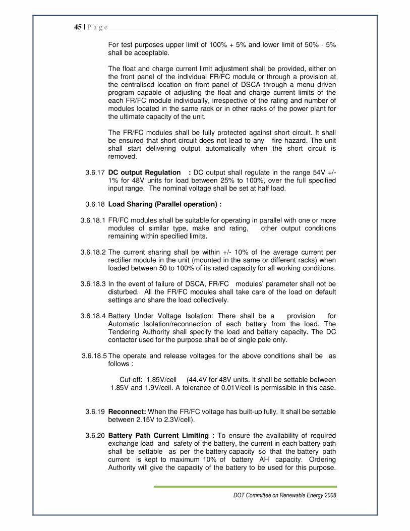
For test purposes upper limit of 100% + 5% and lower limit of 50% - 5% shall be acceptable.
The float and charge current limit adjustment shall be provided, either on the front panel of the individual FR/FC module or through a provision at the centralised location on front panel of DSCA through a menu driven program capable of adjusting the float and charge current limits of the each FR/FC module individually, irrespective of the rating and number of modules located in the same rack or in other racks of the power plant for the ultimate capacity of the unit. The FR/FC modules shall be fully protected against short circuit. It shall be ensured that short circuit does not lead to any fire hazard. The unit shall start delivering output automatically when the short circuit is removed.
3.6.17 DC output Regulation : DC output shall regulate in the range 54V +/-
1% for 48V units for load between 25% to 100%, over the full specified input range. The nominal voltage shall be set at half load.
3.6.18 Load Sharing (Parallel operation) :
3.6.18.1 FR/FC modules shall be suitable for operating in parallel with one or more
modules of similar type, make and rating, other output conditions remaining within specified limits.
3.6.18.2 The current sharing shall be within +/- 10% of the average current per rectifier module in the unit (mounted in the same or different racks) when loaded between 50 to 100% of its rated capacity for all working conditions.
3.6.18.3 In the event of failure of DSCA, FR/FC modules’ parameter shall not be disturbed. All the FR/FC modules shall take care of the load on default settings and share the load collectively.
3.6.18.4 Battery Under Voltage Isolation: There shall be a provision for Automatic Isolation/reconnection of each battery from the load. The Tendering Authority shall specify the load and battery capacity. The DC contactor used for the purpose shall be of single pole only.
3.6.18.5 The operate and release voltages for the above conditions shall be as follows :
Cut-off: 1.85V/cell (44.4V for 48V units. It shall be settable between 1.85V and 1.9V/cell. A tolerance of 0.01V/cell is permissible in this case.
3.6.19 Reconnect: When the FR/FC voltage has built-up fully. It shall be settable
between 2.15V to 2.3V/cell).
3.6.20 Battery Path Current Limiting : To ensure the availability of required exchange load and safety of the battery, the current in each battery path shall be settable as per the battery capacity so that the battery path current is kept to maximum 10% of battery AH capacity. Ordering Authority will give the capacity of the battery to be used for this purpose.

46 | P a g e
DOT Committee on Renewable Energy 2008
For the type approval the manufacturer shall demonstrate the facility and undertake to make provision as per order.
3.6.21 Temperature Compensation for Battery: There shall be provision
for monitoring the temperature of battery and consequent arrangement for Automatic temperature compensation of the FR/FC (in Auto float/charge mode) output voltage to match the battery temperature dependant charge characteristics. The output voltage of the rectifier in Float/Charge operation shall decrease or increase at the rate of 72mV (24 cells battery@ 3mV per cell) and 18mV ( 6 cells battery @ 3mV per cell) per degree increase or decrease in temperature over the set voltage. The output voltage shall decrease till the open circuit voltage of the battery is reached. The open circuit voltage range shall be settable between 2.1V/cell to 2.2V/cell. At this voltage the power plant voltage get locked and further increase in temperature shall not decrease the voltage further. This voltage shall also remain locked till the temperature falls below the value corresponding to set value. When the output voltage reaches 55.8V, due to increase in the output voltage owing to decrease in temperature, it shall get locked at this voltage and any further decrease in temperature shall not lead to further rise in the output voltage of the power plant. This voltage shall also remain locked till the temperature rises above the value corresponding to set value. A tolerance +/- 1% may be acceptable over the rates as specified above. The nominal distance between the battery and power plant may be 20 metres. The manufacturer shall provide the necessary sensor and cord for the purpose with the power plant. Failure of temperature compensation circuit including sensors (including the open or short circuit) shall create an alarm and shall not lead to abnormal change in output voltage. Proper sign-writing shall be made in DSCA and both ends of temperature compensation cord for its easy termination.
3.6.22 Protections: In addition to the requirements given above, the charge
controller shall also provide for the following protections :
3.6.23 AC Input : There shall be an automatic arrangement to provide galvanic isolation at the AC input of the FR/FC module whenever the input voltage is beyond the specified operating range ( 90V to 300V), with suitable alarm indication. The FR/FC module shall resume normal working automatically when the input is restored within the working limits. Hysteresis within specified working limits shall not cause shutting down of the FR/FC. A tolerance of +/-5V may be acceptable for protection and alarm operation. Reconnection shall occur at a voltage, 10V lower than the set voltage high isolation limit and 10V higher than the lower set limit to avoid hunting. The circuitry used for sensing the voltage for operation of isolation/ reconnection device shall be able to withstand a voltage 15% higher than the specified extreme limit of isolation.
3.6.24 D. C. Over voltage :
a) Each rectifier module shall be fitted with an internal over- voltage protection circuit. In case output DC voltage exceeds –56V, the over voltage protection circuit shall operate and shut-off the faulty module. A tolerance of +/-0.01V/cell is permitted in this case. Restoration of the module shall be through a reset switch/push button.

47 | P a g e
DOT Committee on Renewable Energy 2008
b) Shutting-off of faulty FR/FC module shall not affect the operation of other FR/FCs operating in the rack. c) Operation of over-voltage shut down shall be suitably indicated on the module and also extended to monitoring/control unit
d) The circuit design shall ensure protection against the discharge of the Battery through the FR/FC module in any case.
e) The over voltage protection circuit failure shall not cause any safety hazard.
f) Over Load/Short Circuit: The FR/FC modules shall be fully
protected against short circuit. It shall be ensured that short circuit does not lead to any fire hazard. The unit shall start delivering output automatically when the short circuit is removed.
3.6.25 Alarm Indications on SMPS:
A. On FR/FC: a. FR/FC Over voltage b. FR/FC Under voltage or Output Fail c. FR/FC Overload (Voltage Droop) d. Fan fail (due to any reason) All the above alarm Indications shall be extended to DSCA as FR/FC fail.
B. On DSCA: SMPS output voltage High : above 55.6V/Low below 45.6V a) FR/FC fail (any failure condition as in “A” Above) b) Mains Out of range c) Unit Over Load d) Mains "ON"/Battery Discharge e) Temp. Compensation fail f) Battery Fail or No Battery (separate for each Battery) g) Battery isolated from the load(due to any reason) h) Lightning and surge protection Stage II Fail
4. Environmental Requirements: The system shall be designed to work
satisfactorily under all the environmental conditions as specified in this clause. SPV modules, charge controller, mounting structure and batteries shall be capable of working in a saline atmosphere in coastal areas and shall be free from any corrosion at any period of time in compliance with the requirements of relevant clauses of QM-333. SPV Modules, Charge controller & battery shall also be capable to withstand the rigors of transportation, handling & working satisfactorily as specified in Category B2 of QM-333 including Corrosion (salt mist) and high altitude (up to 3000 meters) tests.

48 | P a g e
DOT Committee on Renewable Energy 2008
5. Specification for Wind Generator
The small wind turbine is required for the operation of Base Transceiver Stations (BTS) in areas with deficit grid power and sufficient wind power for the operation of such turbine. The turbine and its associated circuitry is expected to supply 42 to 58 volts regulated DC to the telecommunications load at BTS. The following clauses provide the Generic Requirements for the turbines.
5.1 Technical specifications
5.1.1 Capacity 4-5 kW (as per requirement)
5.1.2 Type Horizontal Axis - Battery Charger /
Aerogenerator to be used as hybrid system in
conjunction with SPV
5.1.2 Swept Area < 200 sq.m.
5.1.3 Start up Wind Speed 2.5 – 3.0 m/s.
5.1.4 Cut in wind speed 3.0 m/s
5.1.5 Rated wind speed 11 – 14 m/s
5.1.6 Cut out wind speed 25 m/s
5.1.7 Furling wind speed > 15 m/s
5.1.8 Survival Wind Speed > 50 – 60 m/s
5.1.9 Design Life time 20 years
5.2 Mechanical specifications
5.2.1 Type 2/3 bladed up wind
5.2.2 Blade profile NACA
5.2.3 Blade Material Glass/Carbon fibre reinforced plastic
5.2.4 Rotor regulation Pitch / Stall regulated
5.2.5 Generator Transmission Direct Drive
5.2.6 Yaw system Active / passive, upwind tracking
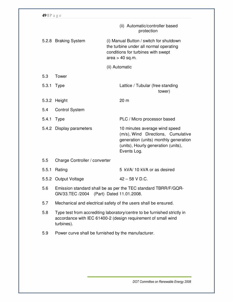
5.2.7 Over speed protection (i) Auto Tail furling system.
49 | P a g e
DOT Committee on Renewable Energy 2008
(ii) Automatic/controller based protection
5.2.8 Braking System (i) Manual Button / switch for shutdown
the turbine under all normal operating
conditions for turbines with swept
area > 40 sq.m.
(ii) Automatic
5.3 Tower
5.3.1 Type Lattice / Tubular (free standing
tower)
5.3.2 Height 20 m
5.4 Control System
5.4.1 Type PLC / Micro processor based
5.4.2 Display parameters 10 minutes average wind speed
(m/s), Wind Directions, Cumulative
generation (units) monthly generation
(units), Hourly generation (units),
Events Log.
5.5 Charge Controller / converter
5.5.1 Rating 5 kVA/ 10 kVA or as desired
5.5.2 Output Voltage 42 – 58 V D.C.
5.6 Emission standard shall be as per the TEC standard TBRR/F/GQR-
GN/33.TEC /2004 (Part) Dated 11.01.2008.
5.7 Mechanical and electrical safety of the users shall be ensured.
5.8 Type test from accrediting laboratory/centre to be furnished strictly in
accordance with IEC 61400-2 (design requirement of small wind
turbines).
5.9 Power curve shall be furnished by the manufacturer.
50 | P a g e
DOT Committee on Renewable Energy 2008
6. Cabling & interconnections
• All cables shall be confirming to IS 694
• Only PVC Copper cables shall be used
• Size of cables shall be so selected to keep the voltage drop and losses to the minimum
7. Earthing
The array structure shall be grounded properly using adequate number of
grounding kits. All metal casing/shielding of the plant shall be thoroughly
grounded to ensure safety of the power plant.
51 | P a g e
DOT Committee on Renewable Energy 2008
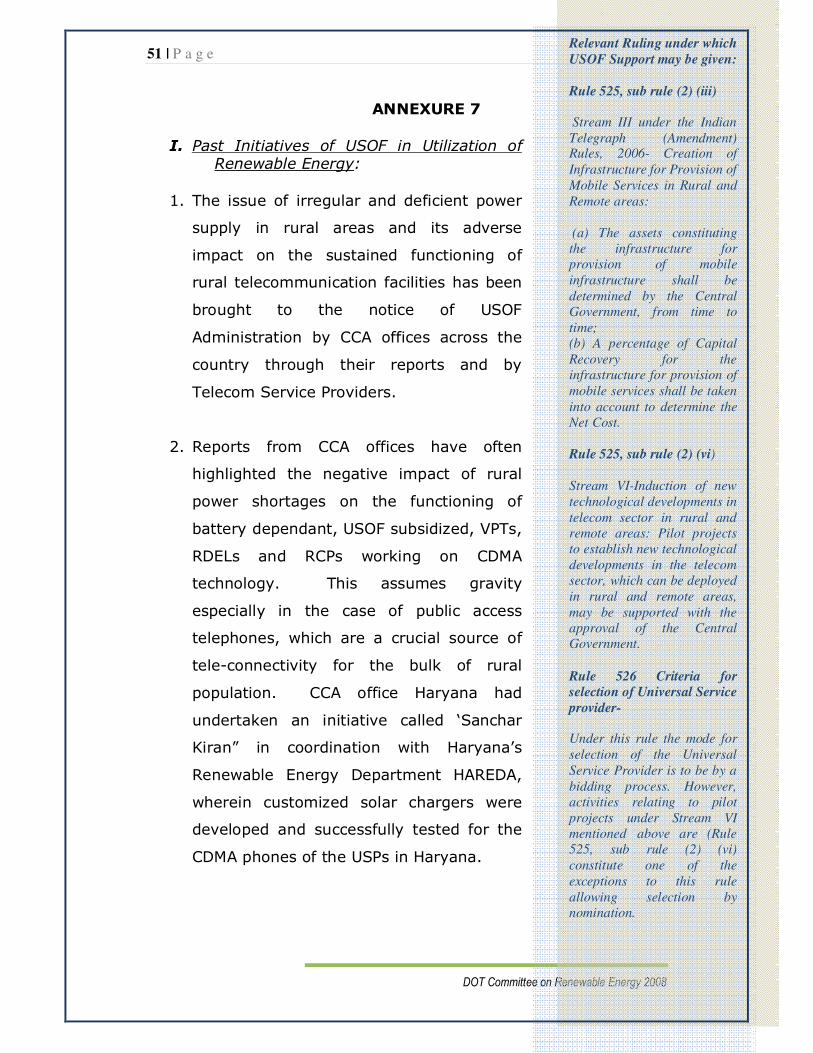
ANNEXURE 7
I. Past Initiatives of USOF in Utilization of Renewable Energy:
1. The issue of irregular and deficient power
supply in rural areas and its adverse
impact on the sustained functioning of
rural telecommunication facilities has been
brought to the notice of USOF
Administration by CCA offices across the
country through their reports and by
Telecom Service Providers.
2. Reports from CCA offices have often
highlighted the negative impact of rural
power shortages on the functioning of
battery dependant, USOF subsidized, VPTs,
RDELs and RCPs working on CDMA
technology. This assumes gravity
especially in the case of public access
telephones, which are a crucial source of
tele-connectivity for the bulk of rural
population. CCA office Haryana had
undertaken an initiative called ‘Sanchar
Kiran” in coordination with Haryana’s
Renewable Energy Department HAREDA,
wherein customized solar chargers were
developed and successfully tested for the
CDMA phones of the USPs in Haryana.
Relevant Ruling under which
USOF Support may be given:
Rule 525, sub rule (2) (iii) Stream III under the Indian Telegraph (Amendment) Rules, 2006- Creation of Infrastructure for Provision of Mobile Services in Rural and Remote areas: (a) The assets constituting the infrastructure for provision of mobile infrastructure shall be determined by the Central Government, from time to time; (b) A percentage of Capital Recovery for the infrastructure for provision of mobile services shall be taken into account to determine the Net Cost. Rule 525, sub rule (2) (vi)
Stream VI-Induction of new technological developments in telecom sector in rural and remote areas: Pilot projects to establish new technological developments in the telecom sector, which can be deployed in rural and remote areas, may be supported with the approval of the Central Government.
Rule 526 Criteria for
selection of Universal Service
provider- Under this rule the mode for selection of the Universal Service Provider is to be by a bidding process. However, activities relating to pilot projects under Stream VI mentioned above are (Rule 525, sub rule (2) (vi) constitute one of the exceptions to this rule allowing selection by nomination.
52 | P a g e
DOT Committee on Renewable Energy 2008
3. Subsequently the matter of providing solar back up devices
for CDMA FWT based VPTs was taken up by USOF
Administration with CMD BSNL in a special meeting on
remedial measures to improve the functioning of VPTs held on
16.11.07. BSNL committed that it would float a tender to
provision solar devices for one lakh CDMA FWT VPTs in
villages where the power situation was critical. BSNL
however, requested for subsidy support. Accordingly the
matter was taken up by USOF Administration with MNRE and
it was jointly decided that this pilot project would be
subsidized to the extent of 25% of the tendered cost by
MNRE. Another 25% would be subsidized by USOF. The BSNL
tender for this project has now been floated.
4. During this meeting it had also been decided that
MNRE would assist the USOF in exploring the possibility
of subsidizing hybrid non-conventional power solutions
for telecom installations. In subsequent meetings MNRE
also expressed willingness to provide technical support to
USOF in this regard. The last such meeting held on 2-5-08
under the chairmanship of Secretary, MNRE and was attended
by JA (Finance) USOF and Sr DDG BW. In this meeting the
possibility of jointly supporting pilot projects to demonstrate
the efficacy and cost effectiveness of various combinations of
hybrid sources of renewal energy was discussed.
5. Consequent to the above mentioned meeting, it was
proposed that the option of renewal energy utilization could
be built into the USOF tender for the forthcoming mobile
infrastructure schemes. This issue was discussed with the
IPs/USPs in meetings held at USOF HQ on phase I and phase
II of the mobile infrastructure scheme and they have

53 | P a g e
DOT Committee on Renewable Energy 2008
expressed an active interest in the same. Thereafter, on
invitation by USOF HQ, service providers presented their
views on how the renewable energy could be incorporated in
the power requirement for the mobile infrastructure scheme,
to USOF on 16.7.08.
II. The Importance of Incorporating the use of Renewable
Energy into USOF Schemes for Shared Mobile
Infrastructure in Rural and Remote Areas
1. Phase I of the USOF scheme providing for setting up of about
7871 mobile infrastructure sites in villages without wireless
signal coverage, is already under implementation in rural and
remote areas across the country. As per the feedback
received from the IPs/USPs and the CCA Offices who are
monitoring the progress of the Scheme, it is evident that the
availability of power for rural BTSs is a major constraint in
operationalising mobile services in rural and remote areas.
2. Anticipating the constraint of non availability of the grid
supply, the relevant USOF Agreement for Mobile Phase
Infrastructure (No. 30-148/2007-USF (Part. A) dated
14.5.2007 under clause 10.4 of the Technical Conditions,
provides that in such an event, an additional DG Set (of the
same capacity and features of the mandatory back up DG Set
defined in the Agreement) is to be provided by the IP for the
shared USOF site without any further subsidy support. It has
also been mentioned that in case hybrid power supply
systems with DG sets and SPV systems, or any other
combination is provided, it should meet the specifications as
prescribed in the Agreement.

54 | P a g e
DOT Committee on Renewable Energy 2008
3. It is understood that as of now there would be a fairly
large number of USOF sites which may have to function
continuously with two DG sets on account of non
availability of grid power in the forthcoming few years.
Reports received from the field units indicate that there is
considerable reluctance on the part of IPs towards payment of
the heavy charges of extending the grid supply to USOF sites.
They are also chary of running a second DG set as this entails
additional costs.
4. It has often been expressed by IPs/USPs that the initial
capital cost of installing renewable energy power sources such
as solar or solar wind, hybrid etc, is prohibitive. In the USOF
benchmarking exercise, the cost attributed to the electric
connection (grid) supply has been taken to be around Rs. 3.5
lakhs. Thus it could be said that in the event of non-
availability of the grid supply, around Rs. 3.5 lakhs of funds
(as per USOF benchmark) may be allocated either towards
the second DG set, or installation of renewable energy
capacity. This allocation is clearly inadequate given that the
capital cost per KW of solar power system would be around
Rs.3.5-4 lakh and that of wind power systems be around Rs. 1
lakh. (In comparison to this, an off-grid shared mobile site
would require an initial investment of around 30 -50 lakhs for
a SPV/hybrid system to cater to a combined power
requirement of 6 KW.)
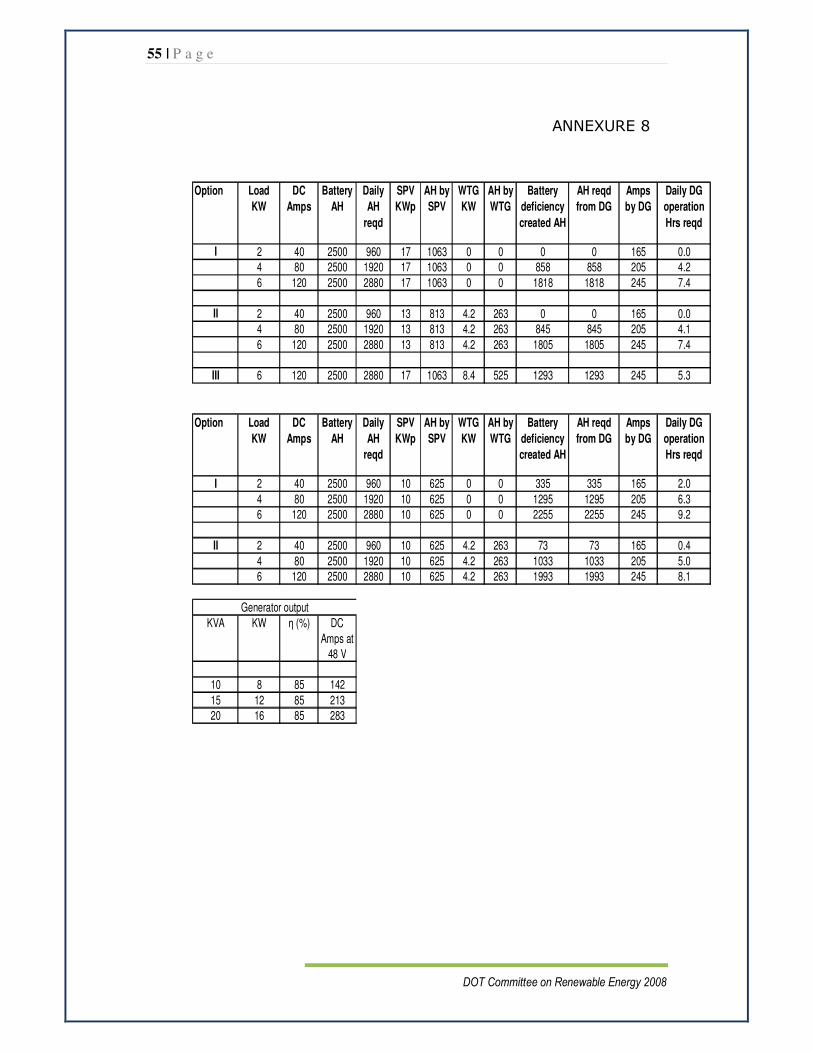
55 | P a g e
DOT Committee on Renewable Energy 2008
ANNEXURE 8
Option Load
KW
DC
Amps
Battery
AH
Daily
AH
reqd
SPV
KWp
AH by
SPV
WTG
KW
AH by
WTG
Battery
deficiency
created AH
AH reqd
from DG
Amps
by DG
Daily DG
operation
Hrs reqd
I 2 40 2500 960 17 1063 0 0 0 0 165 0.0
4 80 2500 1920 17 1063 0 0 858 858 205 4.2
6 120 2500 2880 17 1063 0 0 1818 1818 245 7.4
II 2 40 2500 960 13 813 4.2 263 0 0 165 0.0
4 80 2500 1920 13 813 4.2 263 845 845 205 4.1
6 120 2500 2880 13 813 4.2 263 1805 1805 245 7.4
III 6 120 2500 2880 17 1063 8.4 525 1293 1293 245 5.3
Option Load
KW
DC
Amps
Battery
AH
Daily
AH
reqd
SPV
KWp
AH by
SPV
WTG
KW
AH by
WTG
Battery
deficiency
created AH
AH reqd
from DG
Amps
by DG
Daily DG
operation
Hrs reqd
I 2 40 2500 960 10 625 0 0 335 335 165 2.0
4 80 2500 1920 10 625 0 0 1295 1295 205 6.3
6 120 2500 2880 10 625 0 0 2255 2255 245 9.2
II 2 40 2500 960 10 625 4.2 263 73 73 165 0.4
4 80 2500 1920 10 625 4.2 263 1033 1033 205 5.0
6 120 2500 2880 10 625 4.2 263 1993 1993 245 8.1
KVA KW η (%) DC
Amps at
48 V
10 8 85 142
15 12 85 213
20 16 85 283
Generator output

56 | P a g e
DOT Committee on Renewable Energy 2008
ANNEXURE 9
Case – I ( load 2 KW) – 10 KWp solar system
0
500
1000
1500
2000
2500
1st day 2nd day 3rd day 4th day
Battery (AH) Daily Consumption (AH)
SPV (AH) Balance
Depending upon the set value of Depth of discharge (DOD), DG set can be operated for 20% DOD : DG set is to be operated on 3rd day for 40% DOD : DG set is to be operated on 5th day
for 60% DOD : DG set is to be operated on 7th day or once a week
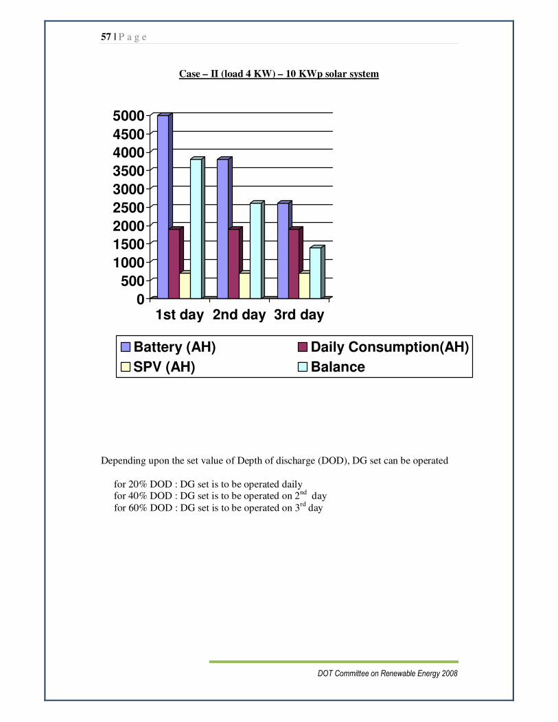
57 | P a g e
DOT Committee on Renewable Energy 2008
Case – II (load 4 KW) – 10 KWp solar system
0
500
1000
1500
2000
2500
3000
3500
4000
4500
5000
1st day 2nd day 3rd day
Battery (AH) Daily Consumption(AH)
SPV (AH) Balance
Depending upon the set value of Depth of discharge (DOD), DG set can be operated for 20% DOD : DG set is to be operated daily for 40% DOD : DG set is to be operated on 2nd day
for 60% DOD : DG set is to be operated on 3rd day

58 | P a g e
DOT Committee on Renewable Energy 2008
Case – III (load 6 KW) – 10 KWp solar system
0
2000
4000
6000
8000
1st day 2nd day 3rd day
Battery (AH)
Daily Consumption (AH)
SPV (AH)
Balance
Depending upon the set value of Depth of discharge (DOD), DG set can be operated for 20% DOD : DG set is to be operated daily for 40% DOD : DG set is to be operated on 2nd day
for 60% DOD : DG set is to be operated on 3rd day
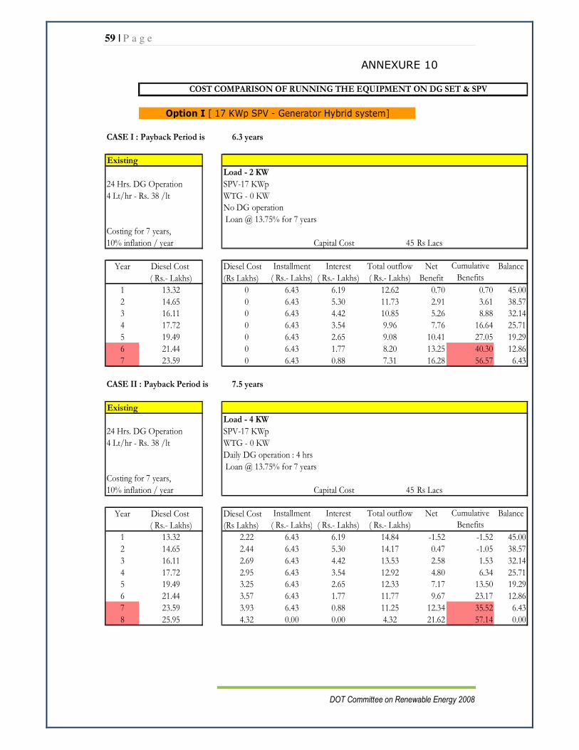
59 | P a g e
DOT Committee on Renewable Energy 2008
ANNEXURE 10
COST COMPARISON OF RUNNING THE EQUIPMENT ON DG SET & SPV
CASE I : Payback Period is 6.3 years
Existing
Load - 2 KW
24 Hrs. DG Operation SPV-17 KWp
4 Lt/hr - Rs. 38 /lt WTG - 0 KW
No DG operation
Loan @ 13.75% for 7 years
Costing for 7 years,
10% inflation / year Capital Cost 45 Rs Lacs
Year Diesel Cost Diesel Cost Installment Interest Total outflow Net Balance
( Rs.- Lakhs) (Rs Lakhs) ( Rs.- Lakhs) ( Rs.- Lakhs) ( Rs.- Lakhs) Benefit
1 13.32 0 6.43 6.19 12.62 0.70 0.70 45.00
2 14.65 0 6.43 5.30 11.73 2.91 3.61 38.57
3 16.11 0 6.43 4.42 10.85 5.26 8.88 32.14
4 17.72 0 6.43 3.54 9.96 7.76 16.64 25.71
5 19.49 0 6.43 2.65 9.08 10.41 27.05 19.29
6 21.44 0 6.43 1.77 8.20 13.25 40.30 12.86
7 23.59 0 6.43 0.88 7.31 16.28 56.57 6.43
CASE II : Payback Period is 7.5 years
Existing
Load - 4 KW
24 Hrs. DG Operation SPV-17 KWp
4 Lt/hr - Rs. 38 /lt WTG - 0 KW
Daily DG operation : 4 hrs
Loan @ 13.75% for 7 years
Costing for 7 years,
10% inflation / year Capital Cost 45 Rs Lacs
Year Diesel Cost Diesel Cost Installment Interest Total outflow Net Balance
( Rs.- Lakhs) (Rs Lakhs) ( Rs.- Lakhs) ( Rs.- Lakhs) ( Rs.- Lakhs)
1 13.32 2.22 6.43 6.19 14.84 -1.52 -1.52 45.00
2 14.65 2.44 6.43 5.30 14.17 0.47 -1.05 38.57
3 16.11 2.69 6.43 4.42 13.53 2.58 1.53 32.14
4 17.72 2.95 6.43 3.54 12.92 4.80 6.34 25.71
5 19.49 3.25 6.43 2.65 12.33 7.17 13.50 19.29
6 21.44 3.57 6.43 1.77 11.77 9.67 23.17 12.86
7 23.59 3.93 6.43 0.88 11.25 12.34 35.52 6.43
8 25.95 4.32 0.00 0.00 4.32 21.62 57.14 0.00
Cumulative
Benefits
Option I [ 17 KWp SPV - Generator Hybrid system]
Cumulative
Benefits
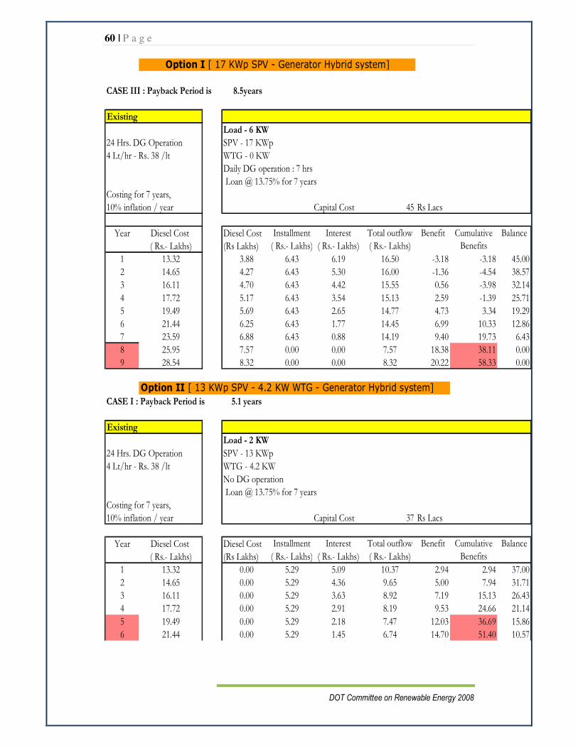
60 | P a g e
DOT Committee on Renewable Energy 2008
CASE III : Payback Period is 8.5years
Existing
Load - 6 KW
24 Hrs. DG Operation SPV - 17 KWp
4 Lt/hr - Rs. 38 /lt WTG - 0 KW
Daily DG operation : 7 hrs
Loan @ 13.75% for 7 years
Costing for 7 years,
10% inflation / year Capital Cost 45 Rs Lacs
Year Diesel Cost Diesel Cost Installment Interest Total outflow Benefit Balance
( Rs.- Lakhs) (Rs Lakhs) ( Rs.- Lakhs) ( Rs.- Lakhs) ( Rs.- Lakhs)
1 13.32 3.88 6.43 6.19 16.50 -3.18 -3.18 45.00
2 14.65 4.27 6.43 5.30 16.00 -1.36 -4.54 38.57
3 16.11 4.70 6.43 4.42 15.55 0.56 -3.98 32.14
4 17.72 5.17 6.43 3.54 15.13 2.59 -1.39 25.71
5 19.49 5.69 6.43 2.65 14.77 4.73 3.34 19.29
6 21.44 6.25 6.43 1.77 14.45 6.99 10.33 12.86
7 23.59 6.88 6.43 0.88 14.19 9.40 19.73 6.43
8 25.95 7.57 0.00 0.00 7.57 18.38 38.11 0.00
9 28.54 8.32 0.00 0.00 8.32 20.22 58.33 0.00
Option II [ 13 KWp SPV - 4.2 KW WTG - Generator Hybrid system]
CASE I : Payback Period is 5.1 years
Existing
Load - 2 KW
24 Hrs. DG Operation SPV - 13 KWp
4 Lt/hr - Rs. 38 /lt WTG - 4.2 KW
No DG operation
Loan @ 13.75% for 7 years
Costing for 7 years,
10% inflation / year Capital Cost 37 Rs Lacs
Year Diesel Cost Diesel Cost Installment Interest Total outflow Benefit Balance
( Rs.- Lakhs) (Rs Lakhs) ( Rs.- Lakhs) ( Rs.- Lakhs) ( Rs.- Lakhs)
1 13.32 0.00 5.29 5.09 10.37 2.94 2.94 37.00
2 14.65 0.00 5.29 4.36 9.65 5.00 7.94 31.71
3 16.11 0.00 5.29 3.63 8.92 7.19 15.13 26.43
4 17.72 0.00 5.29 2.91 8.19 9.53 24.66 21.14
5 19.49 0.00 5.29 2.18 7.47 12.03 36.69 15.86
6 21.44 0.00 5.29 1.45 6.74 14.70 51.40 10.57
Option I [ 17 KWp SPV - Generator Hybrid system]
Cumulative
Benefits
Cumulative
Benefits
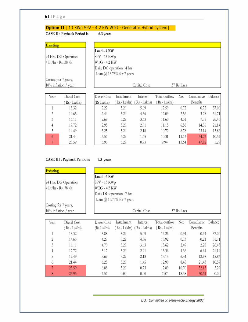
61 | P a g e
DOT Committee on Renewable Energy 2008
Option II [ 13 KWp SPV - 4.2 KW WTG - Generator Hybrid system]
CASE II : Payback Period is 6.3 years
Existing
Load - 4 KW
24 Hrs. DG Operation SPV - 13 KWp
4 Lt/hr - Rs. 38 /lt WTG - 4.2 KW
Daily DG operation : 4 hrs
Loan @ 13.75% for 7 years
Costing for 7 years,
10% inflation / year Capital Cost 37 Rs Lacs
Year Diesel Cost Diesel Cost Installment Interest Total outflow Net Balance
( Rs.- Lakhs) (Rs Lakhs) ( Rs.- Lakhs) ( Rs.- Lakhs) ( Rs.- Lakhs)
1 13.32 2.22 5.29 5.09 12.59 0.72 0.72 37.00
2 14.65 2.44 5.29 4.36 12.09 2.56 3.28 31.71
3 16.11 2.69 5.29 3.63 11.60 4.51 7.79 26.43
4 17.72 2.95 5.29 2.91 11.15 6.58 14.36 21.14
5 19.49 3.25 5.29 2.18 10.72 8.78 23.14 15.86
6 21.44 3.57 5.29 1.45 10.31 11.13 34.27 10.57
7 23.59 3.93 5.29 0.73 9.94 13.64 47.92 5.29
CASE III : Payback Period is 7.3 years
Existing
Load - 6 KW
24 Hrs. DG Operation SPV - 13 KWp
4 Lt/hr - Rs. 38 /lt WTG - 4.2 KW
Daily DG operation : 7 hrs
Loan @ 13.75% for 7 years
Costing for 7 years,
10% inflation / year Capital Cost 37 Rs Lacs
Year Diesel Cost Diesel Cost Installment Interest Total outflow Net Balance
( Rs.- Lakhs) (Rs Lakhs) ( Rs.- Lakhs) ( Rs.- Lakhs) ( Rs.- Lakhs)
1 13.32 3.88 5.29 5.09 14.26 -0.94 -0.94 37.00
2 14.65 4.27 5.29 4.36 13.92 0.73 -0.21 31.71
3 16.11 4.70 5.29 3.63 13.62 2.49 2.28 26.43
4 17.72 5.17 5.29 2.91 13.36 4.36 6.64 21.14
5 19.49 5.69 5.29 2.18 13.15 6.34 12.98 15.86
6 21.44 6.25 5.29 1.45 12.99 8.45 21.43 10.57
7 23.59 6.88 5.29 0.73 12.89 10.70 32.13 5.29
8 25.95 7.57 0.00 0.00 7.57 18.38 50.51 0.00
Cumulative
Benefits
Cumulative
Benefits
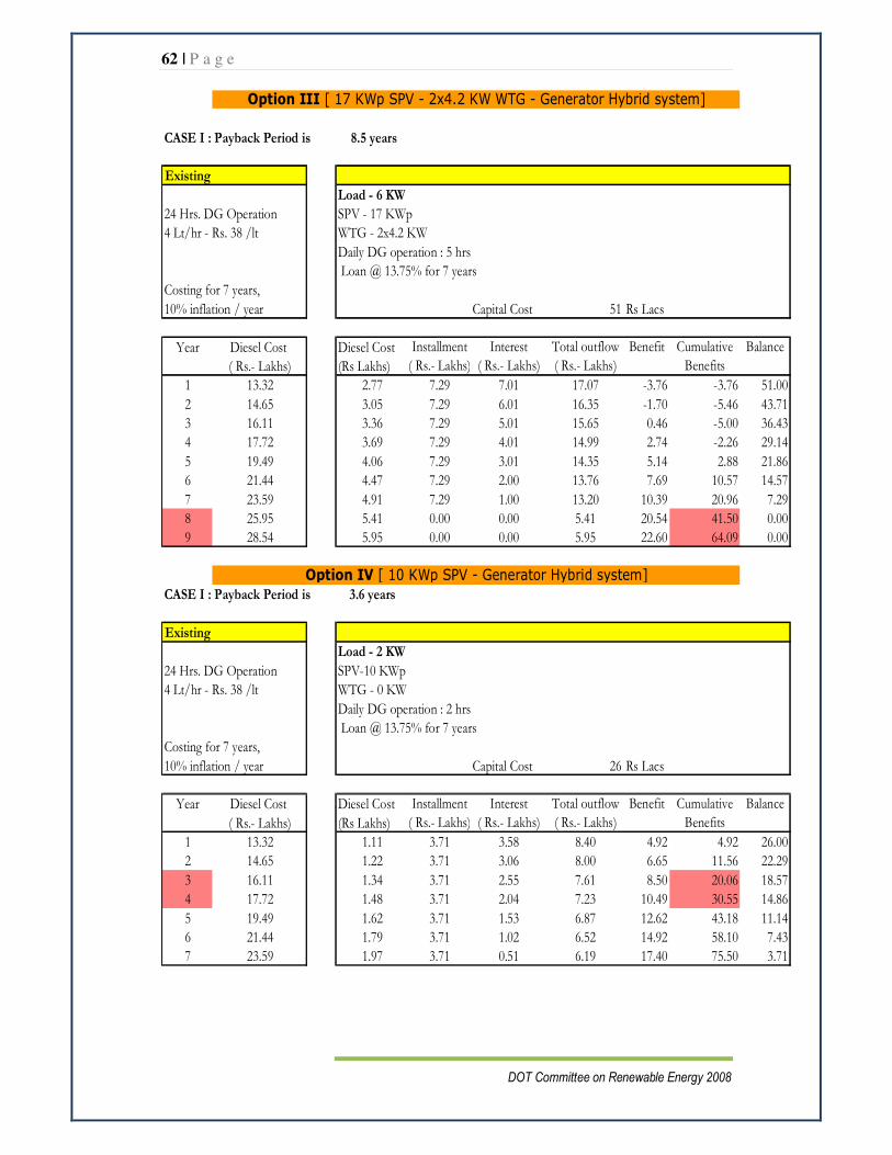
62 | P a g e
DOT Committee on Renewable Energy 2008
CASE I : Payback Period is 8.5 years
Existing
Load - 6 KW
24 Hrs. DG Operation SPV - 17 KWp
4 Lt/hr - Rs. 38 /lt WTG - 2x4.2 KW
Daily DG operation : 5 hrs
Loan @ 13.75% for 7 years
Costing for 7 years,
10% inflation / year Capital Cost 51 Rs Lacs
Year Diesel Cost Diesel Cost Installment Interest Total outflow Benefit Balance
( Rs.- Lakhs) (Rs Lakhs) ( Rs.- Lakhs) ( Rs.- Lakhs) ( Rs.- Lakhs)
1 13.32 2.77 7.29 7.01 17.07 -3.76 -3.76 51.00
2 14.65 3.05 7.29 6.01 16.35 -1.70 -5.46 43.71
3 16.11 3.36 7.29 5.01 15.65 0.46 -5.00 36.43
4 17.72 3.69 7.29 4.01 14.99 2.74 -2.26 29.14
5 19.49 4.06 7.29 3.01 14.35 5.14 2.88 21.86
6 21.44 4.47 7.29 2.00 13.76 7.69 10.57 14.57
7 23.59 4.91 7.29 1.00 13.20 10.39 20.96 7.29
8 25.95 5.41 0.00 0.00 5.41 20.54 41.50 0.00
9 28.54 5.95 0.00 0.00 5.95 22.60 64.09 0.00
CASE I : Payback Period is 3.6 years
Existing
Load - 2 KW
24 Hrs. DG Operation SPV-10 KWp
4 Lt/hr - Rs. 38 /lt WTG - 0 KW
Daily DG operation : 2 hrs
Loan @ 13.75% for 7 years
Costing for 7 years,
10% inflation / year Capital Cost 26 Rs Lacs
Year Diesel Cost Diesel Cost Installment Interest Total outflow Benefit Balance
( Rs.- Lakhs) (Rs Lakhs) ( Rs.- Lakhs) ( Rs.- Lakhs) ( Rs.- Lakhs)
1 13.32 1.11 3.71 3.58 8.40 4.92 4.92 26.00
2 14.65 1.22 3.71 3.06 8.00 6.65 11.56 22.29
3 16.11 1.34 3.71 2.55 7.61 8.50 20.06 18.57
4 17.72 1.48 3.71 2.04 7.23 10.49 30.55 14.86
5 19.49 1.62 3.71 1.53 6.87 12.62 43.18 11.14
6 21.44 1.79 3.71 1.02 6.52 14.92 58.10 7.43
7 23.59 1.97 3.71 0.51 6.19 17.40 75.50 3.71
Cumulative
Benefits
Cumulative
Benefits
Option III [ 17 KWp SPV - 2x4.2 KW WTG - Generator Hybrid system]
Option IV [ 10 KWp SPV - Generator Hybrid system]

63 | P a g e
DOT Committee on Renewable Energy 2008
CASE II : Payback Period is 4.5 years
Existing
Load - 4 KW
24 Hrs. DG Operation SPV-10 KWp
4 Lt/hr - Rs. 38 /lt WTG - 0 KW
Daily DG operation : 6 hrs
Loan @ 13.75% for 7 years
Costing for 7 years,
10% inflation / year Capital Cost 26 Rs Lacs
Year Diesel Cost Diesel Cost Installment Interest Total outflow Benefit Balance
( Rs.- Lakhs) (Rs Lakhs) ( Rs.- Lakhs) ( Rs.- Lakhs) ( Rs.- Lakhs)
1 13.32 3.33 3.71 3.58 10.62 2.70 2.70 26.00
2 14.65 3.66 3.71 3.06 10.44 4.21 6.90 22.29
3 16.11 4.03 3.71 2.55 10.30 5.82 12.72 18.57
4 17.72 4.43 3.71 2.04 10.19 7.53 20.25 14.86
5 19.49 4.87 3.71 1.53 10.12 9.37 29.63 11.14
6 21.44 5.36 3.71 1.02 10.10 11.35 40.98 7.43
7 23.59 5.90 3.71 0.51 10.12 13.47 54.44 3.71
CASE III : Payback Period is 5.8 years
Existing
Load - 6 KW
24 Hrs. DG Operation SPV - 10 KWp
4 Lt/hr - Rs. 38 /lt WTG - 0 KW
Daily DG operation : 9 hrs
Loan @ 13.75% for 7 years
Costing for 7 years,
10% inflation / year Capital Cost 26 Rs Lacs
Year Diesel Cost Diesel Cost Installment Interest Total outflow Benefit Balance
( Rs.- Lakhs) (Rs Lakhs) ( Rs.- Lakhs) ( Rs.- Lakhs) ( Rs.- Lakhs)
1 13.32 4.99 3.71 3.58 12.28 1.03 1.03 26.00
2 14.65 5.49 3.71 3.06 12.27 2.38 3.41 22.29
3 16.11 6.04 3.71 2.55 12.31 3.80 7.21 18.57
4 17.72 6.65 3.71 2.04 12.40 5.32 12.53 14.86
5 19.49 7.31 3.71 1.53 12.56 6.94 19.47 11.14
6 21.44 8.04 3.71 1.02 12.78 8.67 28.13 7.43
7 23.59 8.85 3.71 0.51 13.07 10.52 38.65 3.71
Option IV [ 10 KWp SPV - Generator Hybrid system]
Cumulative
Benefits
Cumulative
Benefits

64 | P a g e
DOT Committee on Renewable Energy 2008
CASE I : Payback Period is 4 years
Existing
Load - 2 KW
24 Hrs. DG Operation SPV - 10 KWp
4 Lt/hr - Rs. 38 /lt WTG - 4.2 KW
Daily DG operation : 1 hrs
Loan @ 13.75% for 7 years
Costing for 7 years,
10% inflation / year Capital Cost 29 Rs Lacs
Year Diesel Cost Diesel Cost Installment Interest Total outflow Benefit Balance
( Rs.- Lakhs) (Rs Lakhs) ( Rs.- Lakhs) ( Rs.- Lakhs) ( Rs.- Lakhs)
1 13.32 0.55 4.14 3.99 8.69 4.63 4.63 29.00
2 14.65 0.61 4.14 3.42 8.17 6.48 11.11 24.86
3 16.11 0.67 4.14 2.85 7.66 8.45 19.55 20.71
4 17.72 0.74 4.14 2.28 7.16 10.56 30.12 16.57
5 19.49 0.81 4.14 1.71 6.66 12.83 42.95 12.43
6 21.44 0.89 4.14 1.14 6.18 15.27 58.22 8.29
7 23.59 0.98 4.14 0.57 5.70 17.89 76.11 4.14
CASE II : Payback Period is 5 years
Existing
Load - 4 KW
24 Hrs. DG Operation SPV - 10 KWp
4 Lt/hr - Rs. 38 /lt WTG - 4.2 KW
Daily DG operation : 5 hrs
Loan @ 13.75% for 7 years
Costing for 7 years,
10% inflation / year Capital Cost 29 Rs Lacs
Year Diesel Cost Diesel Cost Installment Interest Total outflow Benefit Balance
( Rs.- Lakhs) (Rs Lakhs) ( Rs.- Lakhs) ( Rs.- Lakhs) ( Rs.- Lakhs)
1 13.32 2.77 4.14 3.99 10.90 2.41 2.41 29.00
2 14.65 3.05 4.14 3.42 10.61 4.03 6.45 24.86
3 16.11 3.36 4.14 2.85 10.35 5.76 12.21 20.71
4 17.72 3.69 4.14 2.28 10.11 7.61 19.82 16.57
5 19.49 4.06 4.14 1.71 9.91 9.58 29.40 12.43
6 21.44 4.47 4.14 1.14 9.75 11.69 41.09 8.29
7 23.59 4.91 4.14 0.57 9.63 13.96 55.06 4.14
Option V [ 10 KWp SPV - 4.2 KW WTG - Generator Hybrid system]
Cumulative
Benefits
Cumulative
Benefits

65 | P a g e
DOT Committee on Renewable Energy 2008
CASE III : Payback Period is 6 years
Existing
Load - 6 KW
24 Hrs. DG Operation SPV - 10 KWp
4 Lt/hr - Rs. 38 /lt WTG - 4.2 KW
Daily DG operation : 8 hrs
Loan @ 13.75% for 7 years
Costing for 7 years,
10% inflation / year Capital Cost 29 Rs Lacs
Year Diesel Cost Diesel Cost Installment Interest Total outflow Benefit Balance
( Rs.- Lakhs) (Rs Lakhs) ( Rs.- Lakhs) ( Rs.- Lakhs) ( Rs.- Lakhs)
1 13.32 4.44 4.14 3.99 12.57 0.75 0.75 29.00
2 14.65 4.88 4.14 3.42 12.44 2.20 2.95 24.86
3 16.11 5.37 4.14 2.85 12.36 3.75 6.70 20.71
4 17.72 5.91 4.14 2.28 12.33 5.39 12.09 16.57
5 19.49 6.50 4.14 1.71 12.35 7.14 19.24 12.43
6 21.44 7.15 4.14 1.14 12.43 9.01 28.25 8.29
7 23.59 7.86 4.14 0.57 12.58 11.01 39.27 4.14
Option V [ 10 KWp SPV - 4.2 KW WTG - Generator Hybrid system]
Cumulative
Benefits
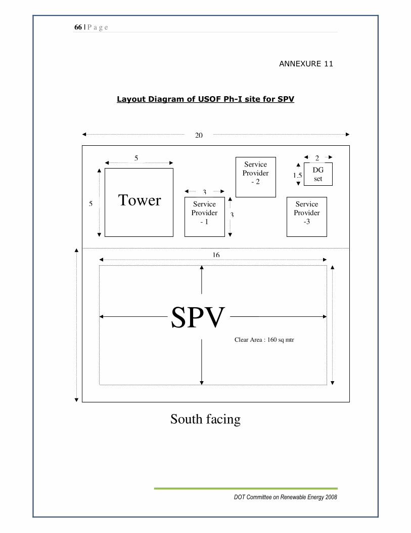
66 | P a g e
DOT Committee on Renewable Energy 2008
ANNEXURE 11
Layout Diagram of USOF Ph-I site for SPV
South facing
Tower
Service Provider
- 2
DG set
Service Provider
-3
SPV
Service Provider
- 1
20
5
5
3
3
1.5
2
16
Clear Area : 160 sq mtr
Top Related