


Languages
Pages
Legal


Sl. No. Description 3.15MVA
1 Name and address of the Manufacturer
a) Transformer
b) HV & LV Bushings
c) Bimetallic connectors
d) Transformer Oil
e) On load tap changer
f) Instruments
g) Neutral Bushing CTs
2 Service ( Indoor / Outdoor )
3 Normal continuous rating in KVA under site conditions at all taps :
a) HV winding (KVA)
b) LV winding (KVA)
4 Rated Voltage
a) HV winding (KV )
b) LV winding (KV)
5 Rated frequency (Hz)
6 No. of phases
7 Type of transformer
8 Connections
a) HV winding
b) LV winding
9 Connections symbols
HV – LV
10 Tappings
a) Range
b) Number of steps
c) Position of tapping on HT winding for high voltage variation
11 Reference ambient temperatures
a) Maximum ambient air temperature (0C)
b) Maximum daily average ambient temperature (0C)
c) Minimum ambient air temperature (0C)
d) Maximum yearly weighted average ambient temperature (0C)
12 Maximum temperature rise over ambient temperature
a) Top oil by thermometer (0C)
b) HV & LV windings by resistance measurement (0C)
Sl. No. Description
c) Hot Spot Temperature rise of windings(º C)
d) Limit for hot spot temperature for which the transformer is designed (º C)
Bidder's offer

e) Temperature gradient between windings and oil (0C)
f) Type of maximum winding temperature indicator (0C)
13 Voltage to earth for which the star point will be insulated
14 Cooling type
15 Losses
a) No-Load loss at rated voltage & rated frequency (KW)
b) Load loss at rated current at Normal Tap at 750 C (KW )
16 Max. Current density in winding at rated current for normal tap position
a) HV winding (Amps/ sq.mm.)
b) LV winding (Amps / sq.mm.)
17Impedance voltage at rated current ,rated frequency and at 75
0 C expressed as
percentage of rated voltage at :-
a) Principal (normal) tap (%)
b) Highest tap (%)
c) Lowest tap (%)
18 Reactance at rated current & frequency as percentage of rated voltage at:
a) Principal (normal) tap
b) Highest Tap
c) Lowest Tap
19 Resistance at 75º C

a) H.V. winding at normal tap position
b) L.V. winding
c)Resistance voltage drop at 75º C winding temperature expressed as percent of
rated voltage (%)
i) Principal/ normal tap
ii) Highest tap
iii) Lowest tap
20 Insulation level
a) Separate source power frequency voltage withstand
i) HV winding (KV rms)
ii) LV winding (KV rms)
b) Induced over voltage withstand
i) HV winding (KV rms)
ii) LV winding (KV rms)
c) Full wave lightning impulse withstand voltage
Sl. No. Description
i) HV winding (KV peak)
d) Power frequency high voltage tests
i) Test voltage for one minute withstand test on high voltage windings (induced)
ii) Test voltage for one minute withstand test on low voltage windings
iii) Test voltage for one minute withstand test on neutral end of low voltage
windings
e) Lightning impulse withstand tests

i) Impulse test on high voltage winding 1.2/50 µ sec full wave withstand (KV peak)
ii) Impulse test on low voltage winding 1.2/50 µ sec full wave withstand (KV peak)
iii) Wave form for impulse test
21No load current, no load loss, no load power factor at normal ratio and frequency
(Amp/ KW/ P.F.)
a) 10 percent of rated voltage
b) 25 percent of rated voltage
c) 50 percent of rated voltage
d) 85 percent of rated voltage
e) 100 percent of rated voltage
f) 105 percent of rated voltage
g) 110 percent of rated voltage
h) 112.5 percent of rated voltage
i) 115 percent of rated voltage
j) 120 percent of rated voltage
k) 121 percent of rated voltage
22 Efficiency at 75º C at unity power factor
a) Full load
b) 75% load
c) 50% load
d) 25% load

23(a)The minimum percentage of load at which the transformer will run at maximum
efficiency (%)
b) Maximum efficiency of the transformer
24 Regulation at full load at 75º C
a) At unity power factor (%)
b) At 0.8 power factor (lagging) (%)
25 Core data
a) Grade of core material used
b) Thickness of core plate lamination (mm)
c) Whether core laminations are of HIB cold rolled grain oriented
Sl. No. Description
d) Details of oil ducts in core, if any
i) Whether in the plane & at right angle to the plane of winding
ii) Across the plane of lamination
e) i) Insulation of core lamination
ii) Insulation of core plates
iii) Type of core joints(Mitred or Mitred Step-lap)
26 Flux density
a) Designed maximum flux density at rated voltage and rated frequency (Tesla)

b)Designed maximum operating flux density which the transformer can withstand for
one minute at normal tap (Tesla)
c)Designed maximum operating flux density which the transformer can withstand for
five seconds at normal tap (Tesla)
27 Inter-Tap insulation
a) Extent of extreme end turns reinforcement
b) Extent of end turns reinforcement
c) Extent of turn adjacent to tapping reinforced
d) Test voltage for 10 seconds 50Hz inter-turn insulation test on (a)
e) Test voltage for 10 seconds 50Hz inter-turn insulation test on (b)
f) Test voltage for 10 seconds 50Hz inter-turn insulation test on (c)
28 Windings:
a) Material
b) Type of windings:
i) HV windings
ii) LV windings
c) Insulation of HV windings
d) Insulation of LV windings
e) Insulation between HV & LV windings
29 Continuous rating under following conditions:

a) At 40ºC ambient air temp. at site
b) At 30ºC ambient air temp. at site
c) At 20ºC ambient air temp. at site
30 Transformer Tank
a) Material
b) Thickness
- Top
- Sides
- Bottom
c) Details of painting
- Inner surface
- Outer surface
31 Dimensions of 3 phase transformers:
Sl. No. Description
a) Max. Height to top of bushings (mm)
b) Over-all length (mm)
c) Over-all breadth (mm)
32Weight data of transformer components : (Tolerance + 5% ) (approximate values
not allowed )
a) Core excluding clamping (Kg)
b) Core with clamping (Kg)
c) HV winding insulated conductor (Kg)
d) LV winding Insulated conductor (Kg)
e) Coils with insulation (Kg.)
f) Core and windings (Kg)
g) Weight of steel (Kg)
h) Fittings and accessories (Kg)
i) Oil required for first filling including 10% extra (ltrs / Kg )

1. Oil in main tank ( Ltrs)
2. Oil in the conservator (Ltrs)
3. Oil in the radiators ( Ltrs )
4. Oil in the OLTC (Ltrs.)
5. Overall total quantity of oil with 10% extra oil for first filling (ltrs / Kg)
j) 1. Transportation weight excluding accessories (Kg)
2. Shipping details
i) Weight of heaviest package (Kg.)
ii) Dimension of largest package (Kg)
k) Untanking weight (Kg)
l) Total weight of transformer with oil and fittings (Kg)
33 Bushing data :
a) Type of bushing insulator
i) HV
ii) LV
iii) Neutral
b) Material of bushing (inner part / outer part)
c) Weight of bushing insulator (Kg.)
d) Quantity of oil in one bushing (lt.)
e) Minimum dry withstand & flash over power frequency voltage of bushing (KV)
f) Minimum wet withstand & flash over power frequency voltage of bushing (KV)

g) Minimum withstand & flashover impulse level (KV)
h) Voltage rating (KV)
i) Current rating (Amps.)
j) Thermal Short Time current & Duration
Sl. No. Description
k) Rated Dynamic current & its duration
l) Cantilever with stand loading
m) Clearance in oil
- phase to phase (mm)
- phase to earth (mm)
n) Creepage distance in oil & air (mm)
o) Minimum level of immersing / medium (oil ) (mm)
p) Maximum pressure of immersing medium (oil) Kg/ cm2
q) Free space required at top for removal of bushings (mm)
r) Angle of mounting
34 Details of CT to be provided in the neutral for REF protection.
a) Outdoor bushing type
b) No. of cores and their function
c) Location (Line / Neutral)
d) Current rating for various cores (Primary / Secondary)
e) VA burden / Knee Point voltage (Core wise)

f) Magnetising current at half knee point voltage. (mA)
g) Classification (PS class) core wise
h) Test voltage
i) Construction details
35 Conservator (Main Transformer and OLTC)
a) Total volume of the Conservator (Cub mtr / Ltr.)
b) Volume of the conservator between the highest and lowest level (Cubic mtr. / Ltrs )
36 Calculated time constants for natural cooling
37 Type of axial coil supports :
a) HV winding
b) LV winding
38 Details of On Load tap changer
a) Make
b) Type
c) Rating
i) Rated Voltage
ii) Rated current
iii) Step voltage
iv) Number of steps
v)Rated Short Circuit Current
Sl. No. Description
d) Whether Diverter switch provided with gas vent and buchholz relay (Yes / No )

e) Whether a separate oil surge relay with trip contacts provided (Yes / No)
f) Pressure relief valve
g) Details of motor device unit housed in kiosk / mounted on tap changer
h)
Whether Remote control panel provided with Control scheme for simultaneous
operation of Tap changer when transformers are running in parallel and
independent control when in independent operation.
i) Details of equipment in the OLTC kiosk
j) Details of OLTC panels
i) automatic tap changer relay
ii) literature of all the relays
iii) dimensions of OLTC, Panel L x B x H
iv) thickness of sheet
v) degree of protection
vi) details of equipment supplied
39 Dispatch details :
a) Approx. mass of heaviest Package (Kg)
b) Approx. dimensions of largest Package
i) Length (mm)
ii) Breadth (mm)
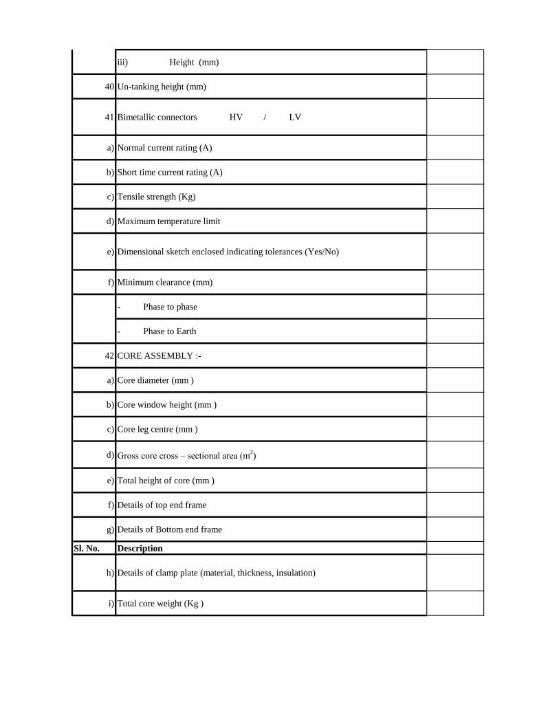
iii) Height (mm)
40 Un-tanking height (mm)
41 Bimetallic connectors HV / LV
a) Normal current rating (A)
b) Short time current rating (A)
c) Tensile strength (Kg)
d) Maximum temperature limit
e) Dimensional sketch enclosed indicating tolerances (Yes/No)
f) Minimum clearance (mm)
- Phase to phase
- Phase to Earth
42 CORE ASSEMBLY :-
a) Core diameter (mm )
b) Core window height (mm )
c) Core leg centre (mm )
d) Gross core cross – sectional area (m2)
e) Total height of core (mm )
f) Details of top end frame
g) Details of Bottom end frame
Sl. No. Description
h) Details of clamp plate (material, thickness, insulation)
i) Total core weight (Kg )

j)Core loss, basing on core loss graph at operating flux density (rated voltage and
rated frequency ) ( KW )
k) Core stacking factor
l) Net core area (Sq.m)
m) Margin towards corner joints, cross-fluxing, dielectric loss (KW)
n) Total core loss at rated voltage and rated frequency (KW )
o) Describe location / method of core grounding
p) Details of core- belting
i) Material , grade and type
ii) Width
iii) Thickness
iv) Fixing method
43 DETAILS OF WINDING
a) Type of winding
b) Material of the winding conductor
c) Maximum current density of windings at rated current and conductor area
d) Whether windings are pre-shrunk ?
e) Whether adjustable coil clamps are provided for HV and LV windings ?
f) Whether steel rings are used for the windings ? If so, whether these are split ?

g)Whether electrostatic shields are provided to obtain uniform voltage distribution in
the windings ?
h) Winding Insulation ( Type & Class )
i) Insulating material , used for
i) H.V winding
ii) LV winding
iii) Tapping connection
j) Insulating material used between
i) L.V and H.V winding
ii) Core & L.V winding
k) H.V to H.V winding between phases
l) Type of axial supports
i) H.V winding
ii) L.V winding
m) Type of radial supports
i) H.V winding
ii) L.V winding
n) Maximum allowable torque on coil clamping bolts
Sl. No. Description
o) Clamping ring details
i) Thickness of ring mm
ii) Diameter of ring mm
iii) No. & size of pressure screw
p) Bare conductor size (mm)
i) HV
ii) LV
q) Insulated conductor size (mm)
i) HV
ii) LV

r) No. of conductor in parallel ( Nos.)
i) HV
ii) LV
s) No. of turns / phase
i) HV
ii) LV
t) No. of discs / phase
i) HV
ii) LV
u) No. of turns / Disc
i) HV
ii) LV
v) Gap between discs (mm )
i) HV
ii) LV
w) Inside diameter (mm )
i) HV
ii) LV
x) Outside diameter (mm )
i) HV
ii) LV
y) Axial height after shrinkage (mm )
i) HV
ii) LV
z) D.C Resistance
i) L.V winding at 750 C (Ohms )
ii) H.V winding at normal tap at 750 C (Ohms )
iii) H.V winding at highest tap at 750 C (Ohms )
iv) H.V winding at lowest tap at 750 C (Ohms )
Sl. No. Description
v) Total I2R losses at 75
0 C for normal tap (KW )

vi) Total I2R losses at 75
0 C for highest tap (KW )
vii) Total I2R losses at 75
0 C for lowest tap (KW )
viii) Stray losses including eddy current losses in winding at 750 C (KW)
a) Normal tap position
b) Highest tap position
c) Lowest tap position
d) Any special measures, taken to reduce eddy current losses and stray losses.
Mention in details
ix) Load losses at 750 C (I
2 R + Stray )
a) Normal tap position (KW )
b) Highest tap position (KW)
c) Lowest tap position (KW )
x)Details of special arrangement, provided to improve surge voltage distribution in
the windings.
44 DETAILS OF TANK :
a) Material of Transformer tank
b) Type of tank
c) Thickness of sheet (No approximate value to be mentioned)
i) Sides (mm)
ii) Bottom (mm )

iii) Cover (mm )
iv ) Radiators (mm)
d) Inside dimensions of main tank (No approximation in dimensions to be used )
i) Length (mm)
ii) Breadth (mm)
iii) Height (mm )
e) Outside dimensions of main tank (No approximation in dimensions to be used )
i) Length (mm)
ii) Breadth (mm)
iii) Height (mm)
f) Vacuum recommended for hot oil circulation (torr / mm of Hg)
g) Vacuum to be maintained during oil filling in transformer tank (torr / mm of Hg)
h) Vacuum to which the tank can be subjected without distortion (torr / mm of Hg)
i) No. of bi-directional wheels provided
j) Track gauge required for the wheels
i) Transverse axis
Sl. No. Description
ii) Longitudinal axis
k)Type and make of pressure relief device and minimum pressure at which it
operates (Kpa )
45 CONSERVATOR :-
a) Thickness of sheet (mm)

b) Size (Dia x length ) (mm)
c) Total volume (Litres)
d) Volume between the highest and lowest visible oil levels (Litres)

5MVA 8MVA
Bidder's offer


CHAPTER:-E21-II
Sl No. Drawing Name Drawing Number 1 Single Line Diagram (GIS) ODSSP/SS/SLD/1
2 Single Line Diagram (AIS) ODSSP/SS/SLD/2 3 Sub-Station Layout ODSSP/SS/1
4 Control Room Layout ODSSP / SS /2
5 T1 Column with Beam Arrangement ODSSP / SS /3 6 T2 Column with Beam Arrangement ODSSP/ SS /4
7 G3 Beam ODSSP/ SS /5 8 33kV V Cross Arm for RS Joist ODSSP/ SS /6
9 33kV SI Structure (Outdoor) ODSSP/ SS /7
10 33kV Outdoor CT Structure (Outdoor) ODSSP/ SS /8 11 Earthmat Layout ODSSP/ SS /9
12 Cable trench ODSSP/ SS /10 13 4 Bolted Tension Clamp ODSSP/ SS /11
14 DP Structure ODSSP/LINE/1 15 400kg 10 Mtr PSC Pole ODSSP/LINE/2
16 300kg 10 Mtr PSC Pole ODSSP/LINE/3
17 11kV V Cross arm for RS Joist Pole ODSSP/LINE/4 18 11kV V Cross arm for PSC Pole ODSSP/LINE/5
19 Earthing Flat Jointing ODSSP/LINE/6 20 Spike ODSSP/LINE/7
21 Foundation for PSC Pol ODSSP/ CIVIL /1
22 Foundation for RS Joist Pole ODSSP/ CIVIL /2
23 Foundation for T1-T2 column ODSSP/ CIVIL /3
24 Transformer Foundation (3.15,5 &8 MVA) ODSSP/ CIVIL /4
25 Transformer Foundation for 100 kVA for (Station Transformer)
ODSSP/ CIVIL /5
26 Retaining Wall ODSSP/ CIVIL /6
27 Drain ODSSP/ CIVIL /7
28 Foundation Plan for T1 & T2 Column with Foundation Bolt for Indoor Arrangement
ODSSP/ CIVIL /8
29 Foundation for 33kV VCB with CT (Outdoor)
ODSSP/ CIVIL /9
30 Compound Wall / Pillar Foundation ODSSP/ CIVIL /10
31 Road Inside Sub-Station ODSSP/ CIVIL /11


CONCRETING OF PSC POLES
‘
ALL PCC - 1:3:6 & RCC - 1:1.5:3
DRG NO.- ODSSP /CIVIL/1

ALL PCC - 1:3:6 & RCC - 1:1.5:3
DRG NO.- ODSSP /CIVIL/2

Foundation for T1 &T2 Columns
ALL PCC - 1:3:6 & RCC - 1:1.5:3
DRG NO.- ODSSP /CIVIL/3

TRANSFORMER FOUNDATION
Rail to Rail Distance-1510 mm for 3.15 MVA & 5 MVA Transformers,
1600mm for 8 MVA Transformers.
ALL PCC - 1:3:6 & RCC - 1:1.5:3
DRG NO.- ODSSP /CIVIL/4

Transformer Foundation for 100 KVA
ALL PCC - 1:3:6 & RCC - 1:1.5:3
BRICK WORK-1:6 MTR.
DRG NO: - ODSSP /CIVIL/5

RETAINING WALL WHERE EARTH FILLING 1 MTR.
ALL PCC - 1:3:6 & RCC - 1:1.5:3
DRG NO.-ODSSP /CIVIL/6

DRAIN
ALL PCC - 1:3:6 & RCC - 1:1.5:3
DRG NO.-ODSSP /CIVIL/7

COMPOUND WALL FOUNDATION
PILLAR FOR COMPOUND WALL WITH FOUNDATION
ALL PCC SHOULD BE 1:3:6 & RCC SHOULD BE 1:1.5:3
DRG NO.-PMU/OPTCL/CIVIL/10

ROAD INSIDE SUB STATION
ALL PCC SHOULD BE 1:3:6 & RCC SHOULD BE 1:1.5:3
DRG NO.-PMU/OPTCL/CIVIL/11

TOILET
2X3M
STORE
ROOM
4X3M
OFFICE
ROOM
4X3M
33
kV
P
AN
EL
CONTROL ROOM CUM SWITCHGEAR BUILDING (AIS & GIS)
FD
R-I
FD
R-II
TRF-I
B/C
TRF-II
FD
R-III
FD
R-IV
INCOMR-I
TRF-I
TRF-II
INCOMR-II
BATTERY
ROOM
2X2M
A B C D
A-CHARGER , B-ACDB, C-RTCC 1 & RTCC 2 , D-RTU
DOOR
33
kV
P
AN
EL
11kV PANEL
FD
R-I
FD
R-II
TRF-I
B/C
TRF-II
FD
R-III
FD
R-IV
INCOMR-I
TRF-I
TRF-II
INCOMR-II
BATTERY
ROOM
2X2M
A B C D
TOILET
2X3M
STORE
ROOM
4X3M
OFFICE
ROOM
4X3M
A.I.S
G.I.S
DRG NO .- ODSSP / SS / 2
11kV PANEL
DOOR


PROPOSED SINGLE LINE DIAGRAM FOR 2X8 MVA, 33/11 kV GIS S/S (33 kV GIS INDOOR, 11 kV GIS INDOOR)
33 kV INCOMMER-I
11kV VCB
8 MVAPOWER TRF
100kVA,33/0.415 kVSTN. TRF
PT
11kV BUS
33kV BUS
LA
11kV VCB
LA
33kV CT400-200/1-1A
33kV CT400-200/1-1-1A
33kV AB SWITCH200A/25kAfor 3 Sec
33kV CT400-200/1-1-1A
33kV VCB1250A/25kA for 3 Sec
33kV VCB1250A/25kA for 3 Sec
11kV ISOLATOR1250A/25kAfor 3 Sec
11kV CT600-300/1-1-1A
11kV CT600-300/1-1-1A11kV
BUS COUPLERVCB
LA
11kV ISOLATOR1250A/25kA
for 3 Sec
11kV CT600-300/1-1A
11kV VCB1250A/25kA
for 3 Sec
33kV VCB1250A/25kA
for 3 Sec
LA
PT PT
LA
33kV CT400-200/1-1A
33kV VCB1250A/25kA for 3 Sec
INDOOR 11kV
LA
11kV ISOLATOR1250A/25kA
for 3 Sec
LA
11kV FEEDER IV
33 kV INCOMER-II
33kV INDOOR GIS
11kV FEEDER I 11kV FEEDER II
LA
11kV FEEDER III
11kV ISOLATOR1250A/25kAfor 3 Sec
33kVDISCONNECTOR
33kV DISCONNECTOR
33kV DISCONNECTOR 33kV DISCONNECTOR
11kV CT600-300/1-1A
11kV VCB1250A/25kA
for 3 Sec
11kV VCB1250A/25kA
for 3 Sec
11kV CT600-300/1-1A
11kV VCB1250A/25kA
for 3 Sec
11kV CT600-300/1-1A
8 MVAPOWER TRF
LA
LA
UG CABLE
LA
S
FUSE
33kV ISOLATOR1250A/25kA for 3 Sec
33 kV ISOLATOR1250A/25kA for 3 Sec
DP
35 sq. mm
100 mtr.
DP
DP
DP
3 kV/ 110/33/ 3, 110/ 3
100 mtr.
3 kV/ 110/33/ 3V
3 kV/ 110/11/ 3V 3 kV/ 110/11/ 3V
DP DP DP DP
DP(H pole)
DP(H pole)
DP
DRAWING NO - ODSSP/ SS/ SLD/ 1

PROPOSED SINGLE LINE DIAGRAM FOR 2X3.15 MVA, 33/11 kV AIS INDOOR S/S(33 kV AIS INDOOR, 11 kV AIS INDOOR)
33 kV INCOMMER- I.
11kV VCB
3.15 MVAPOWER TRF
11kV BUS
33kV BUS
LA
3.15 MVAPOWER TRF
LA
33kV ISOLATOR1250A/25kA for 3 Sec
11kV VCB
LA LA
33kV CT400-200/1-1-1A
33kV VCB1250A/25kA for 3 Sec
11kV ISOLATOR1250A/25kAfor 3 Sec
11kV CT400-200/1-1-1A
11kV CT400-200/1-1-1A
LA
11kV ISOLATOR1250A/25kA
for 3 Sec
11kV CT400-200/1-1A
11kV VCB 1250A/25kAfor 3 Sec
33kV VCB1250A/25kA
for 3 Sec
LA
PT PT
LA
11kV ISOLATOR1250A/25kA
for 3 Sec
LA
11kV FEEDER III
33 kV INCOMER- II
LA
11kV FEEDER I 11kV FEEDER II
11kV ISOLATOR1250A/25kAfor 3 Sec
11kV VCB 1250A/25kAfor 3 Sec
11kV CT400-200/1-1A
LA
11 kV INDOOR
PT
33kV ISOLATOR1250A/25kA for 3 Sec
33kV CT400-200/1-1A
33kV VCB1250A/25kA
for 3 Sec
LA
11kV CT400-200/1-1A
11kV VCB 1250A/25kAfor 3 Sec
11kV VCB 1250A/25kAfor 3 Sec
11kV CT400-200/1-1A
33kV CT400-200/1-1-1A
33kV VCB1250A/25kA for 3 Sec
33 kV INDOOR AIS
11kVBUS COUPLER
VCB
S
FUSE
33kV AB SWITCH200A/25kAfor 3 Sec
UG CABLE
DP
35 sq. mm
33kV CT400-200/1-1A
100 mtr.
DP
DP DP
DP
3 kV/ 110/33/ 3V
3 kV/ 110/11/ 3V
100kVA,33/0.415 kVSTN. TRF
DP (H pole)
DPDPDPDP
DP (H pole)
3 kV/ 110/11/ 3V
11kV FEEDER IV
DRAWING NO - ODSSP/ SS/ SLD/ 2


TOILET
2X3M
STORE
ROOM
4X3M
OFFICE
ROOM
4X3M
33
kV
P
AN
EL
11kV PANEL
ROAD
CONTROL ROOM CUM
SWITCHGEAR BUILDING A.I.S
DOOR
SECU
RITY
LA
ISO
33/11 kV
TRF-2
100KVA,
33/0.4kV
STATION
TRF
LA
ISO
FEEDER-1
LA
ISO
FEEDER-2
LA
ISO
FEEDER-3
LA
ISO
FEEDER-4
INCOMING-2INCOMING-1
33/11 kV
TRF-1
T-1
T-2
T-1
DP USING 150X150
G.I RS JOIST
GATE
33
kV
P
AN
EL
ROAD
CONTROL ROOM CUM
SWITCHGEAR BUILDING G.I.S
DOOR
SECU
RITY
LA
ISO
33/11 kV
TRF-2
LA
ISO
FEEDER-1
LA
ISO
FEEDER-2
LA
ISO
FEEDER-3
LA
ISO
FEEDER-4
INCOMING-2INCOMING-1
33/11 kV
TRF-1
T-1
T-2
T-1
GATE
FD
R-I
FD
R-II
TRF-I
B/C
TRF-II
FD
R-III
FD
R-IV
INCOMR-I
TRF-I
TRF-II
INCOMR-II
11kV PANEL
FD
R-I
FD
R-II
TRF-I
B/C
TRF-II
FD
R-III
FD
R-IV
INCOMR-I
TRF-I
TRF-II
INCOMR-II
100KVA,
33/0.4kV
STATION
TRF
DP USING 150X150
G.I RS JOIST
BATTERY
ROOM
2X2M
A BC
D
A-CHARGER
B-ACDB
C-RTCC 1 & RTCC 2
D-RTU
BATTERY
ROOM
2X2M
A BC
D
A-CHARGER
B-ACDB
C-RTCC 1 & RTCC 2
D-RTU
TOILET
2X3M
STORE
ROOM
4X3M
OFFICE
ROOM
4X3M
DRG NO .- ODSSP / SS / 1
SUB-STATION LAYOUT (AIS & GIS)


E23 - VENDOR LIST FOR MAJOR BOUGHT OUT ITEMS
The List is Subject to modification on the suggestions of prospective bidders and
scrutinisation thereof
SL
No Description Name Of Vendor
1 Transformer
ABB/CGL/Schnider/BHEL/Siemens/Silchar Technology,
Vadodara/ Vijai Electric, Hyderabad/ Tesla Transformers,
Bhopal/ Technical Associates/ Volt Amp, Ahmedabad
1.1 Indoor Switchgear panel with
VCB, CT, IVT, Bus bar Siemens/ABB/CGL/Schnider/ BHEL
4.1 SURGE ARRESTOR CGL/OBLUM/LAMCO/ELPRO International
5.1 Relays ABB/SIEMENS/Schnider/CGL/Easun Reyrole
6.1 ISOLATORS ABB/SIEMENS/SWITCHGEAR & STRUCTURALS/CGL
8 CONDUCTOR APAR/GPIL/ERITECH/STERLITE/VIJAYA/LUMINO/CABC
ON/TIRUPATI/ Gamon/ Vijaya
9
DISC INSULATORS/ POST
INSULATORS/PIN
INSULATORS
BHEL/WS Insulator/MODERN INSULATOR/ADITYA BIRLA
INSULATORS /SRAVANA,M/s Insulators & Electricals
Company, Mandeep ,M.P / Gold Stone
10 PVC INSULATED POWER
AND CONTROL CABLES
NICCO/GLOSTER / CCI/KEI/CRYSTAL/ POLYCAB/ GPIL/
FINOLEX/Universal/ Havells India Ltd./ KEI/ KEC
International Ltd.
11 STATION TRANSFORMER
(BEE STANDARD)
AREVA/ALFA/TESLA/OTPL/TECHNO ASSOCIATE/
SILCHAR TECHNOLOGY/ VIJAYA ELECTRIC
12 LIGHTING FIXTURES PHILIPS/CGL/BAJAJ/HAVELLS
13 CEMENT OPC GRADE ACC/ULTRATECH/KONARK/LAFARGE
14 STEEL SAIL/TATA/RINL
15 GI PIPE TATA/JINDAL
16 AIR CONDITIONER HITACHI/CARRIER/BLUE STAR/VOLTAS/LG
18 SWITCHES ANCHOR/ABB/CONA/HAVELLS/ INDOASIAN
19 MCB L & T /ABB/SIEMENS/MDS/HAVELLS/ INDOASIAN
20 ACB/MCCB L & T /SIEMENS/MERLIN GERIN
21 ACDB
/DCDB/BMK/CONSOLE BOX
MAKTEL SYSTEM (VADODARA)/SARVANA
(CHENNAI)/TECHNOCRAT (CUTTACK).M/s UNITED
ENGINEERS PVT LTD./BOSE ENGINEERS (INDIA) PVT
LTD,KOLKATA/ ALFA AUTOMATION
PVT.LTD,ROURKELA/ RMS AUTOMATION/
CONTINENTAL, Lucknow

22 CLAMPS / CONNECTORS ELECTROMECH TRANSTECH /RASTRAUDYOG
/TYCO/IAC/ASWINI KUMAR & CO. CUTTACK
23 GI BOLTS & NUTS NEXO /GKW/ASP/MAHESWARI(P)FASTENERS & BRIGHT
PVT . LTD ,MEDCHAL
24 VRLA BATTERY &
BATTERY CHARGER
EXIDE, CHLORIDE POWER SYSTEM & SERVICES
(previously CALDYNE) &AMARAJA
25 METERS SECURE LTD/ L&T/ GENUS, Gujarat/ L&G
26 FIRE FIGHITING
EQUIPMENT MINIMAX/CEASE FIRE
27 CABLE JOINT KIT RPG RECHEM/FRONTECH/3M
28 HARD WARE FITTINGS
RASTODYAGA/IAC/MODERN
MALLEABLE/JAINCO/ERITECH/SUPREME/ELECTROMEC
H
Top Related