


Languages
Pages
Legal

Data Sheet
HSMx-A10x-xxxxx PLCC-2, Surface Mount LED Indicator
Description
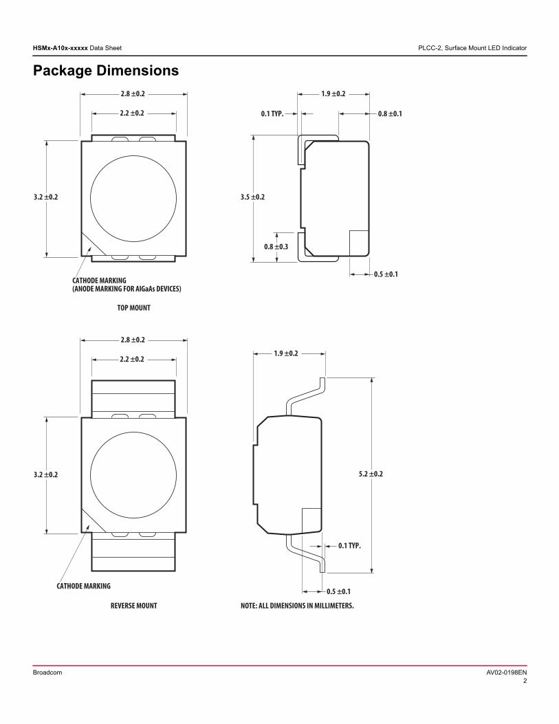
This family of SMT LEDs is packaged in the industry standard PLCC-2 package. These SMT LEDs have high reliability performance and are designed to work under a wide range of environmental conditions. This high reliability feature makes them ideally suited to be used under harsh interior automotive as well as interior signs application conditions.
To facilitate easy pick and place assembly, the LEDs are packed in EIA-compliant tape and reel. Every reel will be shipped in single intensity and color bin, except red color, to provide close uniformity.
These LEDs are compatible with IR solder reflow process. Due to the high reliability feature of these products, they can also be mounted using through-the-wave soldering process.
The super wide viewing angle at 120° makes these LEDs ideally suited for panel, push button, or general backlighting in automotive interior, office equipment, industrial equipment, and home appliances. The flat top emitting surface makes it easy for these LEDs to mate with light pipes. With the built-in reflector pushing up the intensity of the light output, these LEDs are also suitable to be used as LED pixels in interior electronic signs.
Features
Industry standard PLCC-2 package
High reliability LED package
High brightness using AlInGaP and InGaN dice technologies
Available in full selection of colors
Super wide viewing angle at 120
Available in 8 mm carrier tape on 7 inch reel (2000 pieces)
Compatible with both IR and TTW soldering process
Applications Interior automotive
– Instrument panel backlighting
– Central console backlighting
– Switch/push button backlighting
Electronic signs and signals
– Interior full color sign
– Variable message sign
Office automation, home appliances, industrial equipment
– Front panel backlighting
– Push button backlighting
– Display backlighting
CAUTION! HSMN, M, and E-A10x-xxxxx LEDs are Class 2 ESD sensitive. Please observe appropriate precautions during handling and processing. Refer to Broadcom Application Note AN-1142 for additional details.
Broadcom AV02-0198ENFebruary 16, 2018
HSMx-A10x-xxxxx Data Sheet PLCC-2, Surface Mount LED Indicator
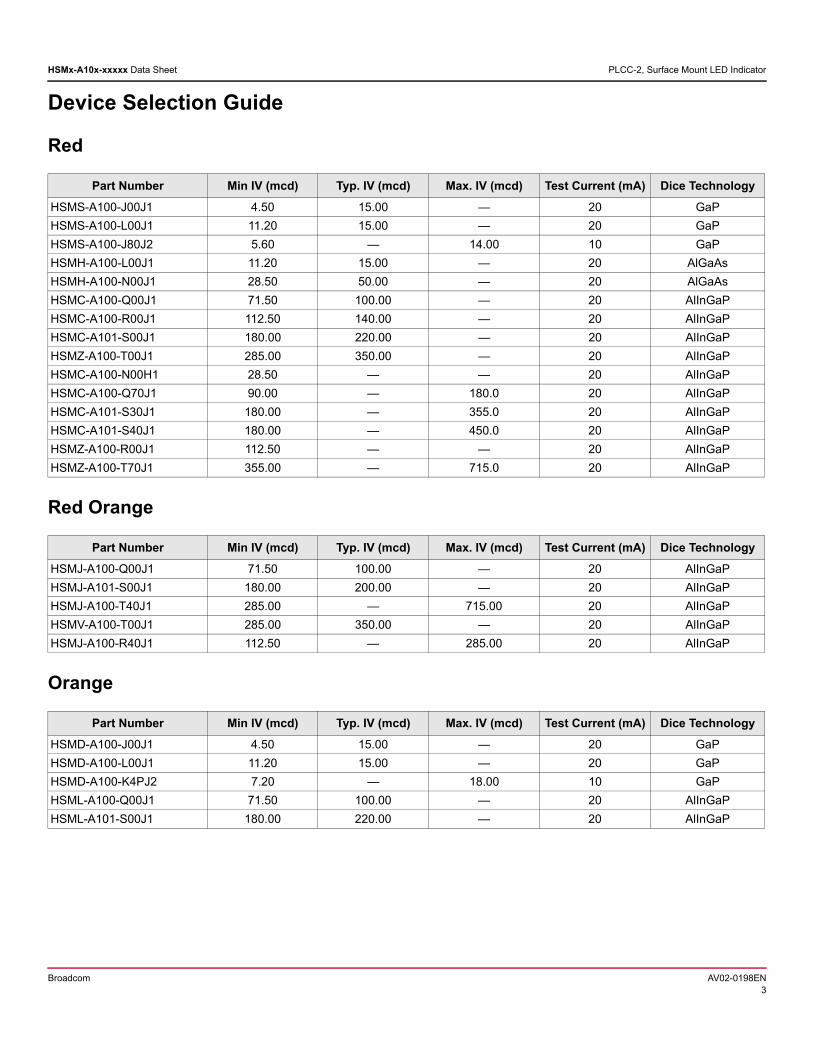
Package Dimensions
0.8 ±0.3
3.5 ±0.2
2.8 ±0.2
0.5 ±0.1
3.2 ±0.2
2.2 ±0.2
1.9 ±0.2
0.1 TYP. 0.8 ±0.1
CATHODE MARKING(ANODE MARKING FOR AlGaAs DEVICES)
5.2 ±0.2
2.8 ±0.2
0.5 ±0.1
0.1 TYP.
3.2 ±0.2
2.2 ±0.21.9 ±0.2
CATHODE MARKING
NOTE: ALL DIMENSIONS IN MILLIMETERS.
TOP MOUNT
REVERSE MOUNT
Broadcom AV02-0198EN2
HSMx-A10x-xxxxx Data Sheet PLCC-2, Surface Mount LED Indicator
Device Selection Guide
Red
Red Orange
Orange
Part Number Min IV (mcd) Typ. IV (mcd) Max. IV (mcd) Test Current (mA) Dice Technology
HSMS-A100-J00J1 4.50 15.00 — 20 GaP
HSMS-A100-L00J1 11.20 15.00 — 20 GaP
HSMS-A100-J80J2 5.60 — 14.00 10 GaP
HSMH-A100-L00J1 11.20 15.00 — 20 AlGaAs
HSMH-A100-N00J1 28.50 50.00 — 20 AlGaAs
HSMC-A100-Q00J1 71.50 100.00 — 20 AlInGaP
HSMC-A100-R00J1 112.50 140.00 — 20 AlInGaP
HSMC-A101-S00J1 180.00 220.00 — 20 AlInGaP
HSMZ-A100-T00J1 285.00 350.00 — 20 AlInGaP
HSMC-A100-N00H1 28.50 — — 20 AlInGaP
HSMC-A100-Q70J1 90.00 — 180.0 20 AlInGaP
HSMC-A101-S30J1 180.00 — 355.0 20 AlInGaP
HSMC-A101-S40J1 180.00 — 450.0 20 AlInGaP
HSMZ-A100-R00J1 112.50 — — 20 AlInGaP
HSMZ-A100-T70J1 355.00 — 715.0 20 AlInGaP
Part Number Min IV (mcd) Typ. IV (mcd) Max. IV (mcd) Test Current (mA) Dice Technology
HSMJ-A100-Q00J1 71.50 100.00 — 20 AlInGaP
HSMJ-A101-S00J1 180.00 200.00 — 20 AlInGaP
HSMJ-A100-T40J1 285.00 — 715.00 20 AlInGaP
HSMV-A100-T00J1 285.00 350.00 — 20 AlInGaP
HSMJ-A100-R40J1 112.50 — 285.00 20 AlInGaP
Part Number Min IV (mcd) Typ. IV (mcd) Max. IV (mcd) Test Current (mA) Dice Technology
HSMD-A100-J00J1 4.50 15.00 — 20 GaP
HSMD-A100-L00J1 11.20 15.00 — 20 GaP
HSMD-A100-K4PJ2 7.20 — 18.00 10 GaP
HSML-A100-Q00J1 71.50 100.00 — 20 AlInGaP
HSML-A101-S00J1 180.00 220.00 — 20 AlInGaP
Broadcom AV02-0198EN3
HSMx-A10x-xxxxx Data Sheet PLCC-2, Surface Mount LED Indicator
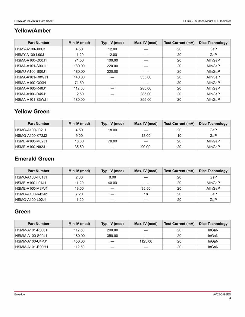
Yellow/Amber
Yellow Green
Emerald Green
Green
Part Number Min IV (mcd) Typ. IV (mcd) Max. IV (mcd) Test Current (mA) Dice Technology
HSMY-A100-J00J1 4.50 12.00 — 20 GaP
HSMY-A100-L00J1 11.20 12.00 — 20 GaP
HSMA-A100-Q00J1 71.50 100.00 — 20 AlInGaP
HSMA-A101-S00J1 180.00 220.00 — 20 AlInGaP
HSMU-A100-S00J1 180.00 320.00 — 20 AlInGaP
HSMA-A101-R8WJ1 140.00 — 355.00 20 AlInGaP
HSMA-A100-Q00H1 71.50 — — 20 AlInGaP
HSMA-A100-R40J1 112.50 — 285.00 20 AlInGaP
HSMA-A100-R45J1 12.50 — 285.00 20 AlInGaP
HSMA-A101-S3WJ1 180.00 — 355.00 20 AlInGaP
Part Number Min IV (mcd) Typ. IV (mcd) Max. IV (mcd) Test Current (mA) Dice Technology
HSMG-A100-J02J1 4.50 18.00 — 20 GaP
HSMG-A100-K72J2 9.00 — 18.00 10 GaP
HSME-A100-M02J1 18.00 70.00 — 20 AlInGaP
HSME-A100-N82J1 35.50 — 90.00 20 AlInGaP
Part Number Min IV (mcd) Typ. IV (mcd) Max. IV (mcd) Test Current (mA) Dice Technology
HSMG-A100-H01J1 2.80 8.00 — 20 GaP
HSME-A100-L01J1 11.20 40.00 — 20 AlInGaP
HSME-A100-M3PJ1 18.00 — 35.50 20 AlInGaP
HSMG-A100-K42J2 7.20 — 18 20 GaP
HSMG-A100-L02J1 11.20 — — 20 GaP
Part Number Min IV (mcd) Typ. IV (mcd) Max. IV (mcd) Test Current (mA) Dice Technology
HSMM-A101-R00J1 112.50 200.00 — 20 InGaN
HSMM-A100-S00J1 180.00 350.00 — 20 InGaN
HSMM-A100-U4PJ1 450.00 — 1125.00 20 InGaN
HSMM-A101-R00H1 112.50 — — 20 InGaN
Broadcom AV02-0198EN4
HSMx-A10x-xxxxx Data Sheet PLCC-2, Surface Mount LED Indicator
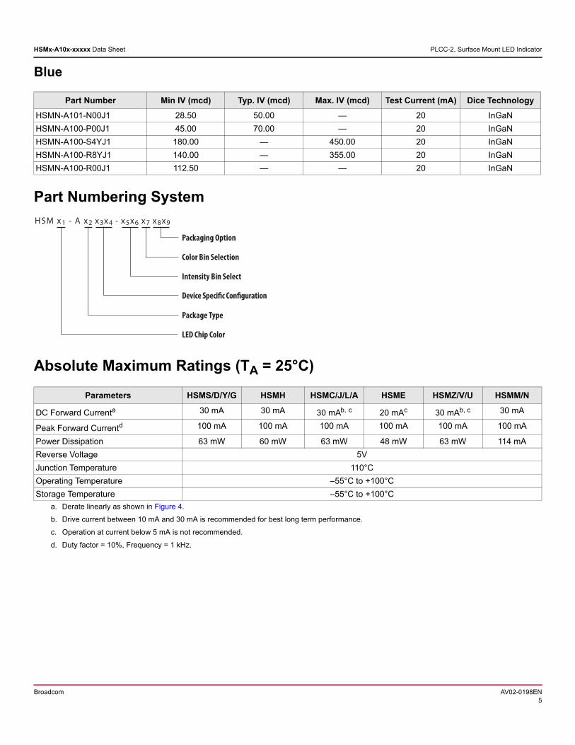
Blue
Part Numbering System
Absolute Maximum Ratings (TA = 25°C)
Part Number Min IV (mcd) Typ. IV (mcd) Max. IV (mcd) Test Current (mA) Dice Technology
HSMN-A101-N00J1 28.50 50.00 — 20 InGaN
HSMN-A100-P00J1 45.00 70.00 — 20 InGaN
HSMN-A100-S4YJ1 180.00 — 450.00 20 InGaN
HSMN-A100-R8YJ1 140.00 — 355.00 20 InGaN
HSMN-A100-R00J1 112.50 — — 20 InGaN
Parameters HSMS/D/Y/G HSMH HSMC/J/L/A HSME HSMZ/V/U HSMM/N
DC Forward Currenta
a. Derate linearly as shown in Figure 4.
30 mA 30 mA 30 mAb, c
b. Drive current between 10 mA and 30 mA is recommended for best long term performance.
c. Operation at current below 5 mA is not recommended.
20 mAc 30 mAb, c 30 mA
Peak Forward Currentd
d. Duty factor = 10%, Frequency = 1 kHz.
100 mA 100 mA 100 mA 100 mA 100 mA 100 mA
Power Dissipation 63 mW 60 mW 63 mW 48 mW 63 mW 114 mA
Reverse Voltage 5V
Junction Temperature 110°C
Operating Temperature –55°C to +100°C
Storage Temperature –55°C to +100°C
Packaging Option
Color Bin Selection
Intensity Bin Select
Package Type
Device Specific Configuration
LED Chip Color
HSM x1 - A x2 x3x4 - x5x6 x7 x8x9
Broadcom AV02-0198EN5
HSMx-A10x-xxxxx Data Sheet PLCC-2, Surface Mount LED Indicator
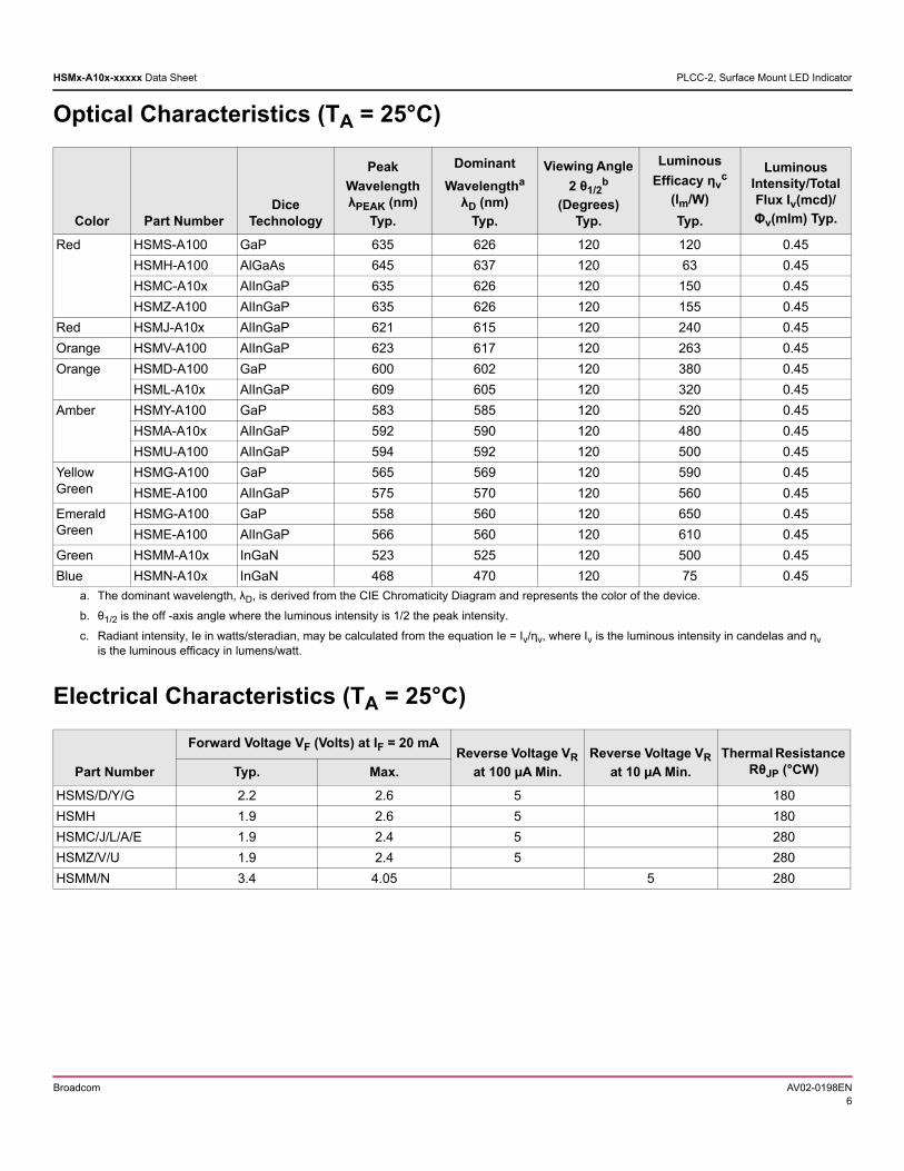
Optical Characteristics (TA = 25°C)
Electrical Characteristics (TA = 25°C)
Color Part NumberDice
Technology
Peak
Wavelength λPEAK (nm)
Typ.
Dominant
Wavelengtha λD (nm)
Typ.
a. The dominant wavelength, λD, is derived from the CIE Chromaticity Diagram and represents the color of the device.
Viewing Angle
2 θ1/2b
(Degrees) Typ.
b. θ1/2 is the off -axis angle where the luminous intensity is 1/2 the peak intensity.
Luminous
Efficacy ηvc
(lm/W)
Typ.
c. Radiant intensity, Ie in watts/steradian, may be calculated from the equation Ie = Iv/ηv, where Iv is the luminous intensity in candelas and ηv is the luminous efficacy in lumens/watt.
Luminous Intensity/Total Flux Iv(mcd)/
Φv(mlm) Typ.
Red HSMS-A100 GaP 635 626 120 120 0.45
HSMH-A100 AlGaAs 645 637 120 63 0.45
HSMC-A10x AlInGaP 635 626 120 150 0.45
HSMZ-A100 AlInGaP 635 626 120 155 0.45
Red HSMJ-A10x AlInGaP 621 615 120 240 0.45
Orange HSMV-A100 AlInGaP 623 617 120 263 0.45
Orange HSMD-A100 GaP 600 602 120 380 0.45
HSML-A10x AlInGaP 609 605 120 320 0.45
Amber HSMY-A100 GaP 583 585 120 520 0.45
HSMA-A10x AlInGaP 592 590 120 480 0.45
HSMU-A100 AlInGaP 594 592 120 500 0.45
Yellow Green
HSMG-A100 GaP 565 569 120 590 0.45
HSME-A100 AlInGaP 575 570 120 560 0.45
Emerald Green
HSMG-A100 GaP 558 560 120 650 0.45
HSME-A100 AlInGaP 566 560 120 610 0.45
Green HSMM-A10x InGaN 523 525 120 500 0.45
Blue HSMN-A10x InGaN 468 470 120 75 0.45
Part Number
Forward Voltage VF (Volts) at IF = 20 mAReverse Voltage VR
at 100 µA Min.
Reverse Voltage VR
at 10 µA Min.
Thermal Resistance RθJP (°CW)Typ. Max.
HSMS/D/Y/G 2.2 2.6 5 180
HSMH 1.9 2.6 5 180
HSMC/J/L/A/E 1.9 2.4 5 280
HSMZ/V/U 1.9 2.4 5 280
HSMM/N 3.4 4.05 5 280
Broadcom AV02-0198EN6
HSMx-A10x-xxxxx Data Sheet PLCC-2, Surface Mount LED Indicator
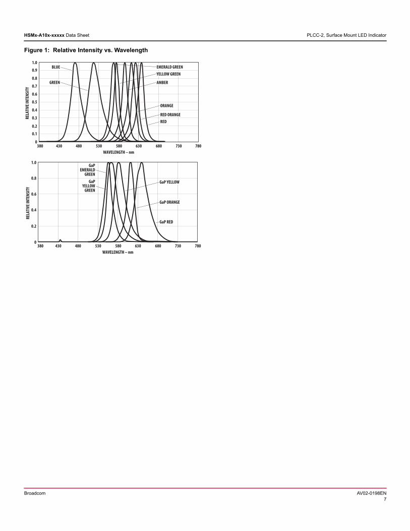
Figure 1: Relative Intensity vs. Wavelength
WAVELENGTH – nm
EMERALD GREEN
RELA
TIVE
INTE
NSIT
Y
1.0
0.8
0380 480 580 680 730 780630530430
BLUE
0.6
0.4
0.2
GREEN
YELLOW GREEN
AMBER
ORANGE
RED ORANGERED
0.1
0.3
0.5
0.7
0.9
WAVELENGTH – nm
RELA
TIVE
INTE
NSIT
Y
1.0
0.8
0380 480 580 680 730 780630530430
GaPEMERALD
GREEN
GaP ORANGE
GaP RED
0.6
0.4
0.2
GaP YELLOWGaPYELLOW
GREEN
Broadcom AV02-0198EN7
HSMx-A10x-xxxxx Data Sheet PLCC-2, Surface Mount LED Indicator
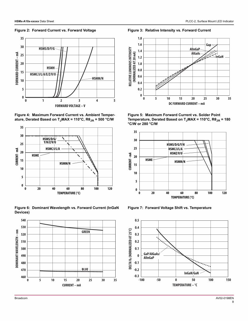
Figure 2: Forward Current vs. Forward Voltage Figure 3: Relative Intensity vs. Forward Current
30FORWARD VOLTAGE – V
0
10
30
35
FORW
ARD
CURR
ENT –
mA
5
5
20
15
25
1 2 4
HSMC/J/L/A/E/Z/V/UHSMM/N
HSMH
HSMS/D/Y/G
020DC FORWARD CURRENT – mA
0
0.4
1.8
REL
ATIV
E LUM
INOU
S INT
ENSI
TY(N
ORM
ALIZ
ED A
T 20 m
A)
35
0.8
0.2
1.0
10
0.6
1.2
25
AlInGaPGap
5 15 30
1.4
1.6
AlGaAsInGaN
Figure 4: Maximum Forward Current vs. Ambient Temper-ature, Derated Based on TJMAX = 110°C, RθJA = 500 °C/W
Figure 5: Maximum Forward Current vs. Solder Point Temperature, Derated Based on TJMAX = 110°C, RθJA = 180 °C/W or 280 °C/W
0
5
10
15
20
25
30
35
0 20 40 60 80 100 120TEMPERATURE (°C)
CURR
ENT -
mA
HSMS/D/G/Y/H/Z/V/U
HSME
HSMM/N
HSMC/J/L/A
0
5
10
15
20
25
30
35
0 20 40 60 80 100 120TEMPERATURE (°C)
CURR
ENT -
mA
HSMS/D/G/Y/HHSMC/J/L/A
HSMZ/V/U
HSMM/NHSME
Figure 6: Dominant Wavelength vs. Forward Current (InGaN Devices)
Figure 7: Forward Voltage Shift vs. Temperature
020CURRENT – mA
460
480
540
DOM
INAN
T WAV
ELEN
GTH
– nm
35
500
470
510
10
490
520
25
GREEN
5 15 30
530
BLUE DELT
A V F
(NOR
MAL
IZED
AT 2
5°C)
-0.3-100
TEMPERATURE – °C
0.5
0.4
0.2
0.1
0
-0.2
15050-50 0 100
-0.1
0.3
GaP/AlGaAs/AlInGaP
InGaN/GaN
Broadcom AV02-0198EN8
HSMx-A10x-xxxxx Data Sheet PLCC-2, Surface Mount LED Indicator
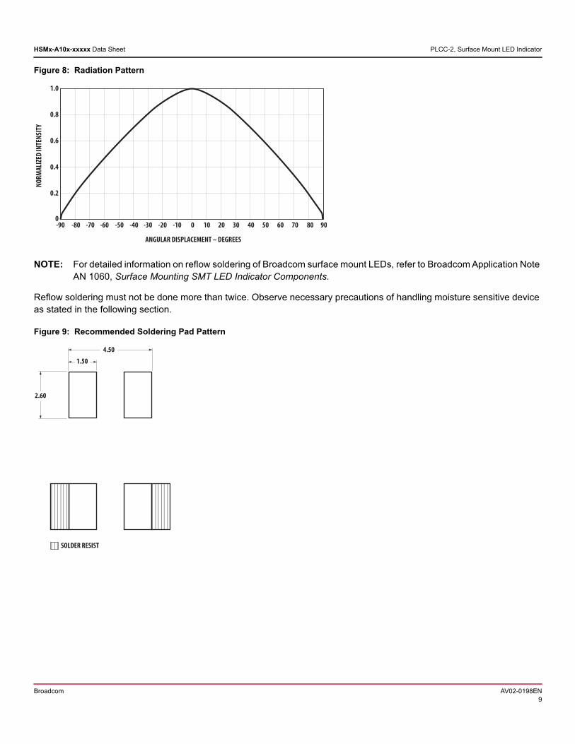
Figure 8: Radiation Pattern
NOTE: For detailed information on reflow soldering of Broadcom surface mount LEDs, refer to Broadcom Application Note AN 1060, Surface Mounting SMT LED Indicator Components.
Reflow soldering must not be done more than twice. Observe necessary precautions of handling moisture sensitive device as stated in the following section.
Figure 9: Recommended Soldering Pad Pattern
NORM
ALIZ
ED IN
TENS
ITY
1.0
0
ANGULAR DISPLACEMENT – DEGREES
0.8
0.6
0.2
0.4
-70 -50 -30 0 20 30 50 70 9002-09- -80 -60 -40 -10 10 40 60 80
2.60
4.50
1.50
SOLDER RESIST
Broadcom AV02-0198EN9
HSMx-A10x-xxxxx Data Sheet PLCC-2, Surface Mount LED Indicator
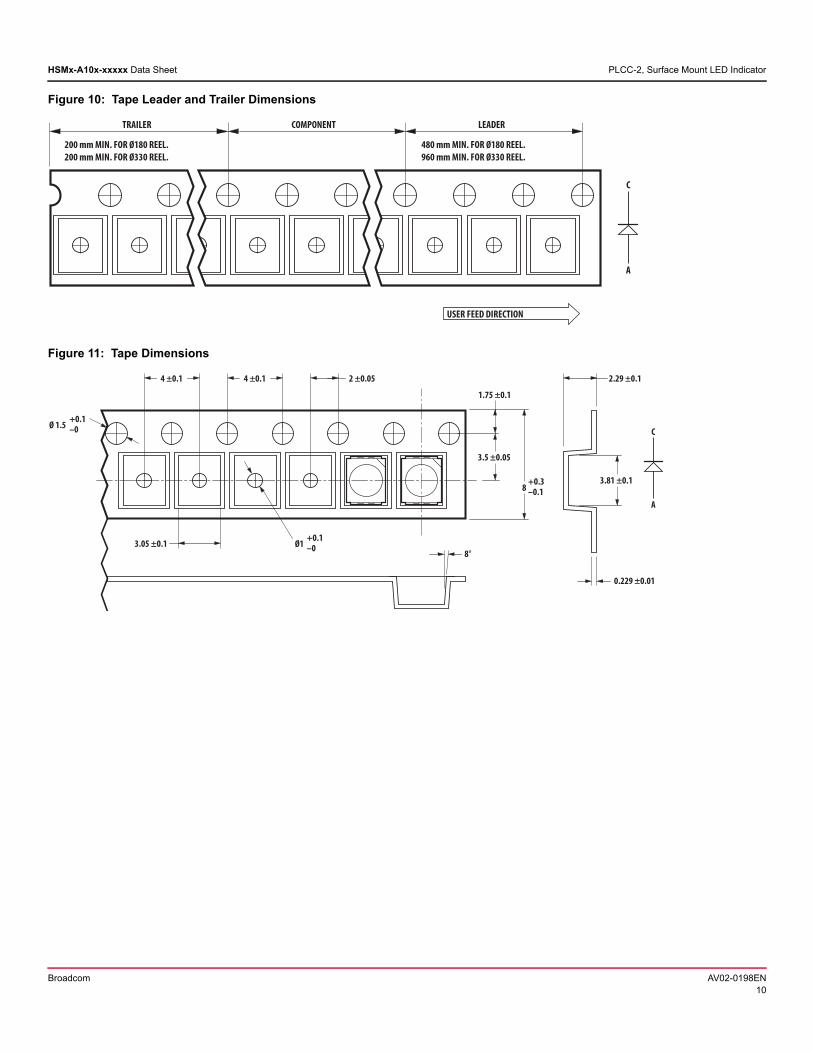
Figure 10: Tape Leader and Trailer Dimensions
Figure 11: Tape Dimensions
200 mm MIN. FOR Ø180 REEL.200 mm MIN. FOR Ø330 REEL.
REDAELTNENOPMOCRELIART
480 mm MIN. FOR Ø180 REEL.960 mm MIN. FOR Ø330 REEL.
C
A
USER FEED DIRECTION
C
A
4 ±0.1 4 ±0.1 2 ±0.05
3.05 ±0.1
3.5 ±0.05
8+0.3–0.1
1.75 ±0.1
3.81 ±0.1
2.29 ±0.1
0.229 ±0.01
8°
Ø 1.5+0.1–0
Ø1+0.1–0
Broadcom AV02-0198EN10
HSMx-A10x-xxxxx Data Sheet PLCC-2, Surface Mount LED Indicator
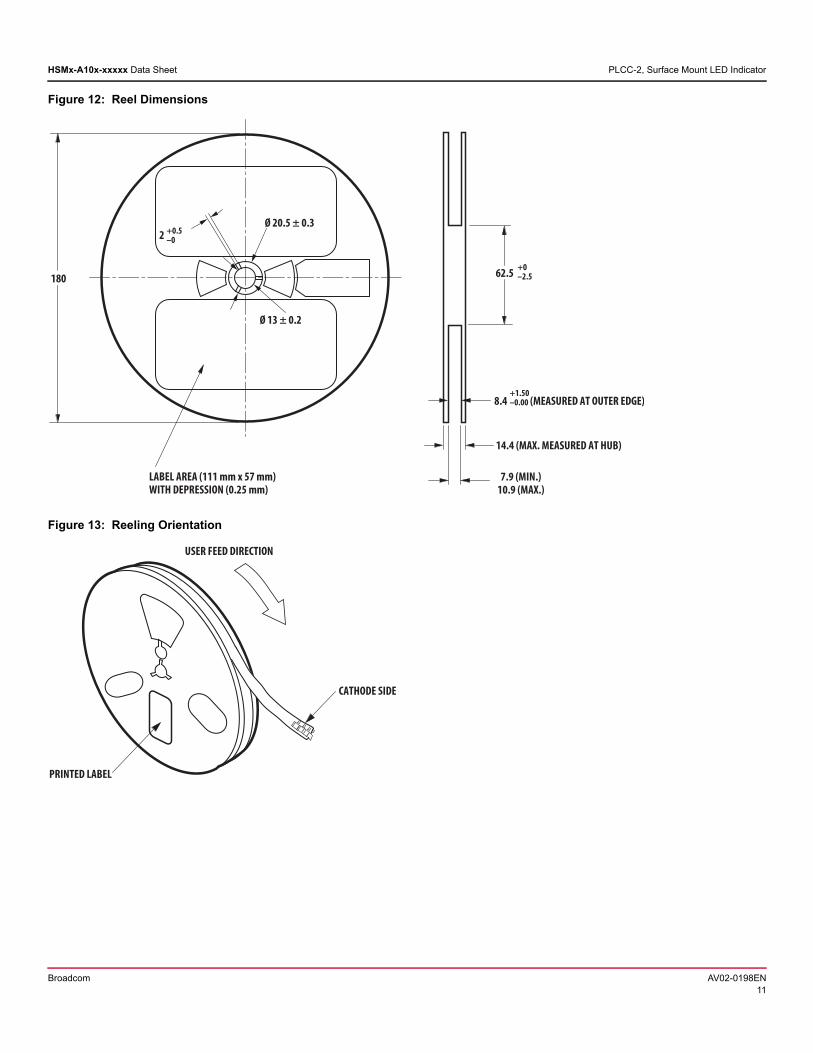
Figure 12: Reel Dimensions
Figure 13: Reeling Orientation
14.4 (MAX. MEASURED AT HUB)
7.9 (MIN.)10.9 (MAX.)
62.5
2 +0.5–0
Ø 20.5 ± 0.3
Ø 13 ± 0.2
+0–2.5
8.4 (MEASURED AT OUTER EDGE)+1.50–0.00
180
LABEL AREA (111 mm x 57 mm)WITH DEPRESSION (0.25 mm)
CATHODE SIDE
PRINTED LABEL
USER FEED DIRECTION
Broadcom AV02-0198EN11
HSMx-A10x-xxxxx Data Sheet PLCC-2, Surface Mount LED Indicator
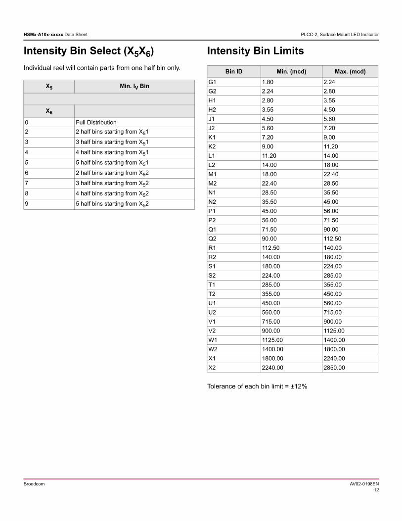
Intensity Bin Select (X5X6)
Individual reel will contain parts from one half bin only.
Intensity Bin Limits
Tolerance of each bin limit = ±12%
X5 Min. IV Bin
X6
0 Full Distribution
2 2 half bins starting from X51
3 3 half bins starting from X51
4 4 half bins starting from X51
5 5 half bins starting from X51
6 2 half bins starting from X52
7 3 half bins starting from X52
8 4 half bins starting from X52
9 5 half bins starting from X52
Bin ID Min. (mcd) Max. (mcd)
G1 1.80 2.24
G2 2.24 2.80
H1 2.80 3.55
H2 3.55 4.50
J1 4.50 5.60
J2 5.60 7.20
K1 7.20 9.00
K2 9.00 11.20
L1 11.20 14.00
L2 14.00 18.00
M1 18.00 22.40
M2 22.40 28.50
N1 28.50 35.50
N2 35.50 45.00
P1 45.00 56.00
P2 56.00 71.50
Q1 71.50 90.00
Q2 90.00 112.50
R1 112.50 140.00
R2 140.00 180.00
S1 180.00 224.00
S2 224.00 285.00
T1 285.00 355.00
T2 355.00 450.00
U1 450.00 560.00
U2 560.00 715.00
V1 715.00 900.00
V2 900.00 1125.00
W1 1125.00 1400.00
W2 1400.00 1800.00
X1 1800.00 2240.00
X2 2240.00 2850.00
Broadcom AV02-0198EN12
HSMx-A10x-xxxxx Data Sheet PLCC-2, Surface Mount LED Indicator
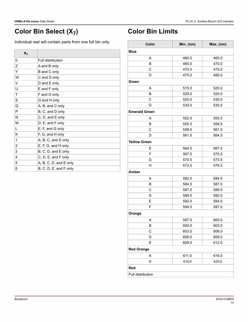
Color Bin Select (X7)
Individual reel will contain parts from one full bin only.
Color Bin Limits
X7
0 Full distribution
Z A and B only
Y B and C only
W C and D only
V D and E only
U E and F only
T F and G only
S G and H only
Q A, B, and C only
P B, C, and D only
N C, D, and E only
M D, E, and F only
L E, F, and G only
K F, G, and H only
1 A, B, C, and D only
2 E, F, G, and H only
3 B, C, D, and E only
4 C, D, E, and F only
5 A, B, C, D, and E only
6 B, C, D, E, and F only
Color Min. (nm) Max. (nm)
Blue
A 460.0 465.0
B 465.0 470.0
C 470.0 475.0
D 475.0 480.0
Green
A 515.0 520.0
B 520.0 525.0
C 525.0 530.0
D 530.0 535.0
Emerald Green
A 552.5 555.5
B 555.5 558.5
C 558.5 561.5
D 561.5 564.5
Yellow Green
E 564.5 567.5
F 567.5 570.5
G 570.5 573.5
H 573.5 576.5
Amber
A 582.0 584.5
B 584.5 587.0
C 587.0 589.5
D 589.5 592.0
E 592.0 594.5
F 594.5 597.0
Orange
A 597.0 600.0
B 600.0 603.0
C 603.0 606.0
D 606.0 609.0
E 609.0 612.0
Red Orange
A 611.0 616.0
B 616.0 620.0
Red
Full distribution
Broadcom AV02-0198EN13
HSMx-A10x-xxxxx Data Sheet PLCC-2, Surface Mount LED Indicator
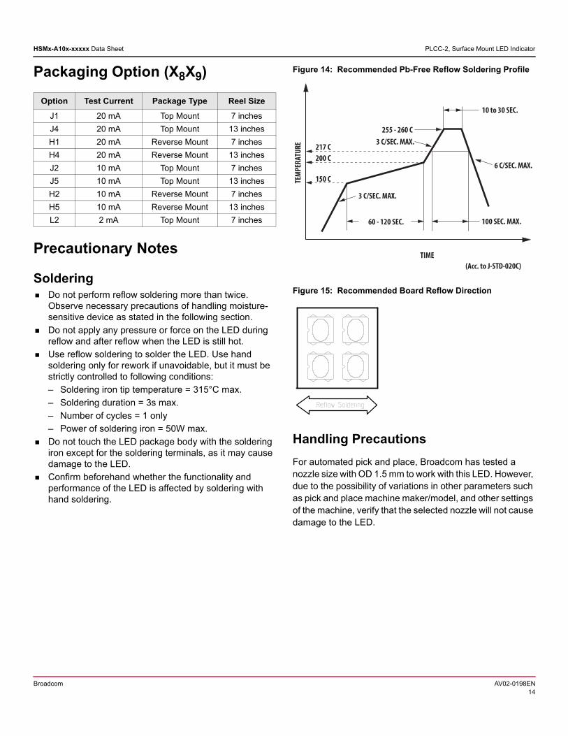
Packaging Option (X8X9)
Precautionary Notes
Soldering Do not perform reflow soldering more than twice.
Observe necessary precautions of handling moisture-sensitive device as stated in the following section.
Do not apply any pressure or force on the LED during reflow and after reflow when the LED is still hot.
Use reflow soldering to solder the LED. Use hand soldering only for rework if unavoidable, but it must be strictly controlled to following conditions:
– Soldering iron tip temperature = 315°C max.
– Soldering duration = 3s max.
– Number of cycles = 1 only
– Power of soldering iron = 50W max.
Do not touch the LED package body with the soldering iron except for the soldering terminals, as it may cause damage to the LED.
Confirm beforehand whether the functionality and performance of the LED is affected by soldering with hand soldering.
Figure 14: Recommended Pb-Free Reflow Soldering Profile
Figure 15: Recommended Board Reflow Direction
Handling Precautions
For automated pick and place, Broadcom has tested a nozzle size with OD 1.5 mm to work with this LED. However, due to the possibility of variations in other parameters such as pick and place machine maker/model, and other settings of the machine, verify that the selected nozzle will not cause damage to the LED.
Option Test Current Package Type Reel Size
J1 20 mA Top Mount 7 inches
J4 20 mA Top Mount 13 inches
H1 20 mA Reverse Mount 7 inches
H4 20 mA Reverse Mount 13 inches
J2 10 mA Top Mount 7 inches
J5 10 mA Top Mount 13 inches
H2 10 mA Reverse Mount 7 inches
H5 10 mA Reverse Mount 13 inches
L2 2 mA Top Mount 7 inches
217 C200 C
60 - 120 SEC.
6 C/SEC. MAX.
3 C/SEC. MAX.
(Acc. to J-STD-020C)
3 C/SEC. MAX.
150 C
255 - 260 C
100 SEC. MAX.
10 to 30 SEC.
TIME
TEM
PERA
TURE
Broadcom AV02-0198EN14
HSMx-A10x-xxxxx Data Sheet PLCC-2, Surface Mount LED Indicator
Handling of Moisture-Sensitive Devices
This product has a Moisture Sensitive Level 2a rating per JEDEC J-STD-020. Refer to Broadcom Application Note AN5305, Handling of Moisture Sensitive Surface Mount Devices for additional details and a review of proper handling procedures.
Before use:
– An unopened moisture barrier bag (MBB) can be stored at <40°C/90% RH for 12 months. If the actual shelf life has exceeded 12 months and the Humidity Indicator Card (HIC) indicates that baking is not required, then it is safe to reflow the LEDs per the original MSL rating.
– Do not open the MBB prior to assembly (for example, for IQC). If unavoidable, MBB must be properly resealed with fresh desiccant and HIC. The exposed duration must be taken in as floor life.
Control after opening the MBB:
– Read the HIC immediately upon opening of MBB.
– Keep the LEDs at <30°/60% RH at all times, and complete all high temperature-related processes, including soldering, curing or rework within 672 hours.
Control for unfinished reel:
Store unused LEDs in a sealed MBB with desiccant or a desiccator at <5% RH.
Control of assembled boards:
If the PCB soldered with the LEDs is to be subjected to other high-temperature processes, store the PCB in a sealed MBB with desiccant or desiccator at <5% RH to ensure that all LEDs have not exceeded their floor life of 168 hours.
Baking is required if:
– The HIC indicator indicates a change in color for 10% and 5%, as stated on the HIC.
– The LEDs are exposed to conditions of >30°C/60% RH at any time.
– The LED's floor life exceeded 168 hours.
The recommended baking condition is: 60±5°C for 20 hours.
Baking can only be done once.
Storage:
The soldering terminals of these Broadcom LEDs are silver plated. If the LEDs are exposed in ambient environment for too long, the silver plating might be oxidized, thus affecting its solderability performance. As such, keep unused LEDs in a sealed MBB with desiccant or in a desiccator at <5% RH.
Application Precautions The drive current of the LED must not exceed the
maximum allowable limit across temperature as stated in the data sheet. Constant current driving is recommended to ensure consistent performance.
Circuit design must cater to the whole range of forward voltage (VF) of the LEDs to ensure the intended drive current can always be achieved.
The LED exhibits slightly different characteristics at different drive currents, which may result in a larger variation of performance (meaning: intensity, wavelength, and forward voltage). Set the application current as close as possible to the test current to minimize these variations.
The LED is not intended for reverse bias. Use other appropriate components for such purposes. When driving the LED in matrix form, ensure that the reverse bias voltage does not exceed the allowable limit of the LED.
Do not use the LED in the vicinity of material with sulfur content or in environments of high gaseous sulfur compounds and corrosive elements. Examples of material that might contain sulfur are rubber gaskets, room- temperature vulcanizing (RTV) silicone rubber, rubber gloves, and so on. Prolonged exposure to such environments may affect the optical characteristics and product life.
White LEDs must not be exposed to acidic environments and must not be used in the vicinity of any compound that may have acidic outgas, such as, but not limited to, acrylate adhesive. These environments have an adverse effect on LED performance.
This LED is designed to have enhanced gas corrosion resistance. Its performance has been tested according to the conditions below:
– IEC 60068-2-43: 25°C/75% RH, H2S 15 ppm, 21 days
– IEC 60068-2-42: 25°C/75% RH, SO2 25 ppm, 21 days
– IEC 60068-2-60: 25°C/75% RH, SO2 200 ppb, NO2 200 ppb, H2S 10 ppb, Cl2 10 ppb, 21 days.
As actual application might not be exactly similar to the test conditions, do verify that the LED will not be damaged by prolonged exposure in the intended environment.
Avoid rapid change in ambient temperature, especially in high-humidity environments, because they cause condensation on the LED.
Broadcom AV02-0198EN15
HSMx-A10x-xxxxx Data Sheet PLCC-2, Surface Mount LED Indicator
If the LED is intended to be used in harsh or outdoor environment, protect the LED against damages caused by rain water, water, dust, oil, corrosive gases, external mechanical stresses, and so on.
Thermal Management
The optical, electrical, and reliability characteristics of the LED are affected by temperature. Keep the junction temperature (TJ) of the LED below the allowable limit at all times. TJ can be calculated as follows:
TJ = TA + RθJ-A x IF x VFmax
where;
TA = ambient temperature (°C)
RθJ-A = thermal resistance from LED junction to ambient (°C/W)
IF = forward current (A)
VFmax = maximum forward voltage (V)
The complication of using this formula lies in TA and RθJ-A. Actual TA is sometimes subjective and hard to determine. RθJ-A varies from system to system depending on design and is usually not known.
Another way of calculating TJ is by using the solder point temperature, TS as follows:
TJ = TS + RθJ-S x IF x VFmax
where;
TS = LED solder point temperature as shown in the following figure (°C)
RθJ-S = thermal resistance from junction to solder point (°C/W)
IF = forward current (A)
VFmax = maximum forward voltage (V)
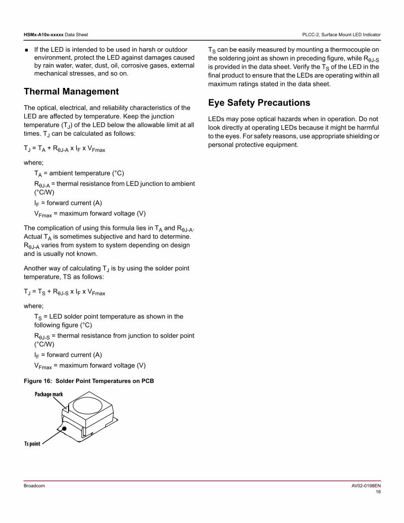
Figure 16: Solder Point Temperatures on PCB
TS can be easily measured by mounting a thermocouple on the soldering joint as shown in preceding figure, while RθJ-S is provided in the data sheet. Verify the TS of the LED in the final product to ensure that the LEDs are operating within all maximum ratings stated in the data sheet.
Eye Safety Precautions
LEDs may pose optical hazards when in operation. Do not look directly at operating LEDs because it might be harmful to the eyes. For safety reasons, use appropriate shielding or personal protective equipment.
Ts point
Package mark
Broadcom AV02-0198EN16
Disclaimer
Broadcom's products and software are not specifically designed, manufactured, or authorized for sale as parts, components, or assemblies for the planning, construction, maintenance, or direct operation of a nuclear facility or for use in medical devices or applications. The customer is solely responsible, and waives all rights to make claims against Broadcom or its suppliers, for all loss, damage, expense, or liability in connection with such use.
Broadcom, the pulse logo, Connecting everything, Avago Technologies, Avago, and the A logo are among the trademarks of Broadcom and/or its affiliates in the United States, certain other countries, and/or the EU.
Copyright © 2017–2018 Broadcom. All Rights Reserved.
The term “Broadcom” refers to Broadcom Limited and/or its subsidiaries. For more information, please visit www.broadcom.com.
Broadcom reserves the right to make changes without further notice to any products or data herein to improve reliability, function, or design. Information furnished by Broadcom is believed to be accurate and reliable. However, Broadcom does not assume any liability arising out of the application or use of this information, nor the application or use of any product or circuit described herein, neither does it convey any license under its patent rights nor the rights of others.
Top Related