


Languages
Pages
Legal


FENet Annual Industry Meeting, Dec 3, 2004M. Juwet and D. Debruyne, KaHo St-LievenFENet Annual Industry Meeting, Dec 3, 2004M. Juwet and D. Debruyne, KaHo St-Lieven
Associatie KULeuven
How to extract more informationfrom a basic tensile test with the
aid of FEA?
Marc Juwet and Dimitri DebruyneKaHo St.-Lieven - KULeuven
Belgium
1

FENet Annual Industry Meeting, Dec 3, 2004M. Juwet and D. Debruyne, KaHo St-Lieven
“Basic” tensile test? •Initial geometry of specimen•Tensile force Fload (⇒ σload)•Elongation ∆L/L0 (⇒ e)
↓
2
FENet Annual Industry Meeting, Dec 3, 2004M. Juwet and D. Debruyne, KaHo St-Lieven
Associatie KULeuven

FENet Annual Industry Meeting, Dec 3, 2004M. Juwet and D. Debruyne, KaHo St-LievenFENet Annual Industry Meeting, Dec 3, 2004M. Juwet and D. Debruyne, KaHo St-Lieven
Associatie KULeuven
Uniform plastic deformation
σtrue = Fload/A = σload (1+e)εtrue = ln(A0/A) = ln(1+e)
Valid only before necking(ultimate tensile strength)
3

FENet Annual Industry Meeting, Dec 3, 2004M. Juwet and D. Debruyne, KaHo St-Lieven
Associatie KULeuven
A growing interest in complex FEA modelling
•Availability of powerful computers–CPU: speed (allows shorter computing times)–RAM: model size (allows higher accuracy)
•Better understanding of FEA in general
•Availability of sophisticated FEA software⇓
Increasing demand for complex FEA calculations(plastic deformation, contact modelling, crash simulations, etc.)
4

FENet Annual Industry Meeting, Dec 3, 2004M. Juwet and D. Debruyne, KaHo St-Lieven
Associatie KULeuven
Material is everything!!!
Every FE simulation starts with the input of material data(elastic and plastic behaviour for a mechanical problem)
↓For the metalforming industry the input of correct
material data is vital to the success of the FE simulation↓
From a basic tensile test one obtains the true plastic behaviour before necking
↓This is sufficient for many applications, but not all
5

FENet Annual Industry Meeting, Dec 3, 2004M. Juwet and D. Debruyne, KaHo St-Lieven
Plastic deformation beyond neckingExample 1: tubehydroforming
→
Necking can occur without fracturing of the tube
Associatie KULeuven
6

FENet Annual Industry Meeting, Dec 3, 2004M. Juwet and D. Debruyne, KaHo St-Lieven
Plastic deformation beyond neckingExample 2: border rolling
→
Circumference of initial hole is enlarged by 100%
Associatie KULeuven
7

FENet Annual Industry Meeting, Dec 3, 2004M. Juwet and D. Debruyne, KaHo St-Lieven
Plastic deformation beyond neckingExample 3: rupture disc (pressure relief)
→
Deformation up to fracture at the nodes
Associatie KULeuven
8

FENet Annual Industry Meeting, Dec 3, 2004M. Juwet and D. Debruyne, KaHo St-Lieven
Goal of this investigation
We have (from basic tensile test)true plastic behaviour before necking
and engineering stress strain relation beyond necking↓
We need true plastic behaviour of material beyondnecking (ultimate tensile strength)
↑We can use
Analytical corrections: Bridgeman (not suited for thin plate)FE simulation of the tensile test (geometry independent)
9
Associatie KULeuven

FENet Annual Industry Meeting, Dec 3, 2004M. Juwet and D. Debruyne, KaHo St-Lieven
Associatie KULeuven
Research so far
Most theoretical studies deal with the question:“Given a certain material model (true stress true strain behaviour), how does necking occur and evolve up to fracture?”Material model ⇒ Theoretical stress strain diagramma
↔Very few studies deal with the far more interestingquestion:“Given an engineering stress strain diagramma, what is the true stress strain behaviour of the material?”Measured stress strain diagramma ⇒ Material model
10

FENet Annual Industry Meeting, Dec 3, 2004M. Juwet and D. Debruyne, KaHo St-Lieven
Associatie KULeuven
Basic Idea of a FE approach
Step 1: Propose a material model (based on reasonable assumptions)
↓Step 2: Simulate the tensile test and construct
the engineering stress strain curve↓
Step 3: Compare to experiment and correct the material model
(go back to step 2 until convergence is reached)
11

FENet Annual Industry Meeting, Dec 3, 2004M. Juwet and D. Debruyne, KaHo St-Lieven
Associatie KULeuven
Every day practice
•Given a certain geometry•Given certain material properties (i.e. conventional stress strain curve)•Given a certain failure mode
⇒ Redesign in a matter of days
⇒ We need a quick way to improve material data input
12

FENet Annual Industry Meeting, Dec 3, 2004M. Juwet and D. Debruyne, KaHo St-Lieven
Associatie KULeuven
Simple approach(fracture is not relevant)
13

FENet Annual Industry Meeting, Dec 3, 2004M. Juwet and D. Debruyne, KaHo St-Lieven
Tensile test on thin plate specimen
Krupkowski Power law: σ = C(ε0 + ε)n
→ C = 540 MPaε0 = 0,57%n = 0,237
Associatie KULeuven
14
FENet Annual Industry Meeting, Dec 3, 2004M. Juwet and D. Debruyne, KaHo St-Lieven
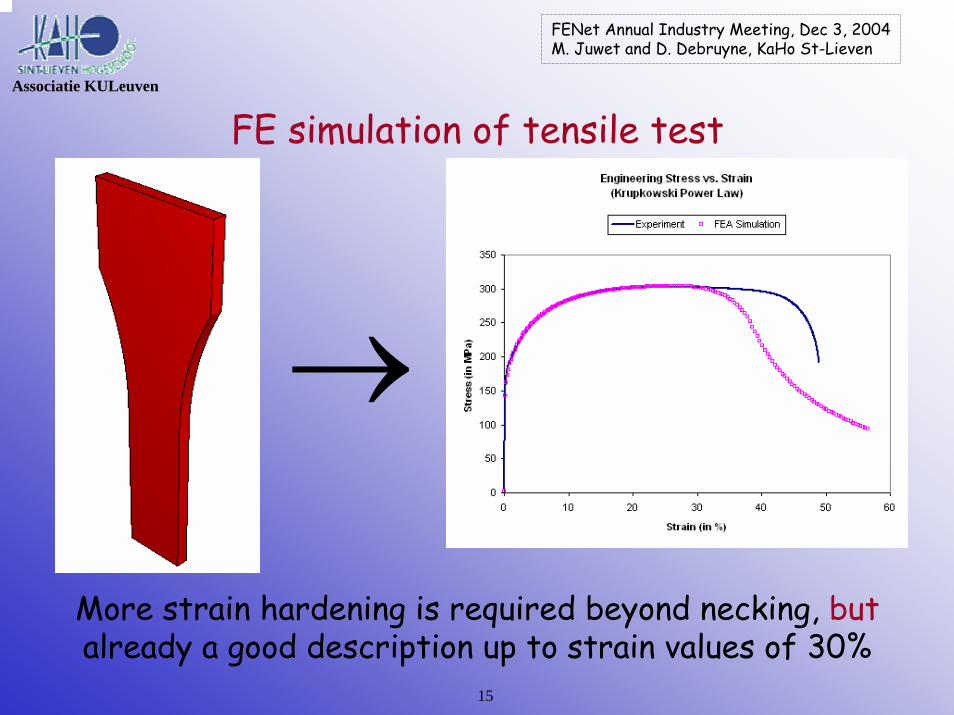
FE simulation of tensile test
More strain hardening is required beyond necking, butalready a good description up to strain values of 30%
→
Associatie KULeuven
15

FENet Annual Industry Meeting, Dec 3, 2004M. Juwet and D. Debruyne, KaHo St-Lieven
Propose a new material model
Plastic behaviour is adjusted beyond necking
Apply Voce equation:
σ = K (1 – m e-nε)
Taken into account thatσ|ε = ε(uts) = σ(uts)dσ/dε|ε = ε(uts) = σ(uts)
Associatie KULeuven
16

FENet Annual Industry Meeting, Dec 3, 2004M. Juwet and D. Debruyne, KaHo St-Lieven
Associatie KULeuven
Iterative FE simulation
Find optimum fit(e.g. least squares)
Satisfactory descriptionup to engineering strainvalues of 45%Local true strain in the necking zone is 85% !!!
This should be sufficient formost metalforming apps
Uniqueness?
17
FENet Annual Industry Meeting, Dec 3, 2004M. Juwet and D. Debruyne, KaHo St-Lieven
Associatie KULeuven
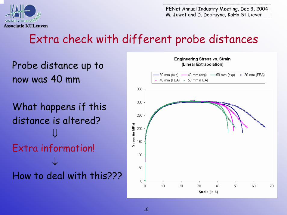
Extra check with different probe distances
Probe distance up tonow was 40 mm
What happens if thisdistance is altered?
⇓Extra information!
↓How to deal with this???
18

FENet Annual Industry Meeting, Dec 3, 2004M. Juwet and D. Debruyne, KaHo St-Lieven
Associatie KULeuven
Less simple approach(fracture is relevant)
19
FENet Annual Industry Meeting, Dec 3, 2004M. Juwet and D. Debruyne, KaHo St-Lieven
Associatie KULeuven
Incorporating fracture
•Many ways to do this– from very simple to very complex– physical and non-physical
•For FE simulation purposes we need– plastic behaviour of the material (stress vs. strain)– ánd damage accumulation (leading to fracture)
•Only relevant for high strain applications
20

FENet Annual Industry Meeting, Dec 3, 2004M. Juwet and D. Debruyne, KaHo St-Lieven
Example: Void material model(proposed by Gurson and extended by Tvergaard)
Based on physical grounds
Damage is accumulated by– Void growth– Void nucleation– Void coalescence
Critical void volume fraction
Loss of stress carrying capacity ⇒ Fracture21
Cu2O inclusionsin a Cu matrix
↓
⇓
Associatie KULeuven

FENet Annual Industry Meeting, Dec 3, 2004M. Juwet and D. Debruyne, KaHo St-Lieven
Void material model – new yield function
Stress state in a material separates into– hydrostatic part p (volume change)– deviatoric part s (plastic deformation)
These combine into the Von Mises stress q
New yield function– Material parameters q1, q2 and q3– Void volume fraction f
Hydrostatic stress contributes to plastic deformation for large voidvolumes (↔ Von Mises yield criterion)
Associatie KULeuven
22

FENet Annual Industry Meeting, Dec 3, 2004M. Juwet and D. Debruyne, KaHo St-Lieven
Associatie KULeuven
Void material model – void growth and nucleation
Change in void volume fraction fduring plastic deformation:
Due to growth:
Due to nucleation:
Material parameters fN, sN and εN(fN ≅ 0.04 sN ≅ 0.05 - 0.1 εN = 0.1 - 0.3)
23

FENet Annual Industry Meeting, Dec 3, 2004M. Juwet and D. Debruyne, KaHo St-Lieven
Associatie KULeuven
Stress vs. strainLess material has towithstand the sameamount of load Fload
Actual stress in the material grains becomesmuch higher as morevoids are formed
⇓
24

FENet Annual Industry Meeting, Dec 3, 2004M. Juwet and D. Debruyne, KaHo St-Lieven
Other stress strain behaviour is required
e.g. quadratic polynomials(by lack of a better alternative)
Associatie KULeuven
25

FENet Annual Industry Meeting, Dec 3, 2004M. Juwet and D. Debruyne, KaHo St-Lieven
Associatie KULeuven
Resulting engineering stress strain relations(after iterative FE simulations)
26
FENet Annual Industry Meeting, Dec 3, 2004M. Juwet and D. Debruyne, KaHo St-Lieven
Associatie KULeuven
ConclusionFE simulation of a basic tensile test can provideadditional information, but …
–from the experimental side: input is needed from more sophisticated tests for comparison purposes (e.g. determinationof void material parameters, true stress strain beyond necking)–from the theoretical side: as for material modelling beyondnecking and towards fracture, much is available, few is widelyapplicable–from the FEA view: uncertainties on element choices, implicit orexplicit scheme, uniqueness of the solution … (e.g. many authorsuse shell elements → incorrect!)
27
FENet Annual Industry Meeting, Dec 3, 2004M. Juwet and D. Debruyne, KaHo St-Lieven
Associatie KULeuven
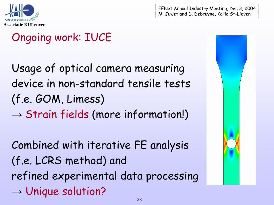
Ongoing work: IUCE
Usage of optical camera measuringdevice in non-standard tensile tests(f.e. GOM, Limess)→ Strain fields (more information!)
Combined with iterative FE analysis(f.e. LCRS method) and refined experimental data processing→ Unique solution?
28

FENet Annual Industry Meeting, Dec 3, 2004M. Juwet and D. Debruyne, KaHo St-Lieven
Any questions?
[email protected]@kahosl.be
Top Related