


Languages
Pages
Legal

How PC’s/Microprocessors Work1
The computer you are using to read this page uses a
microprocessor to do its work. The microprocessor is the heart of
any normal computer, whether it is a desktop machine, a server or a
laptop. The microprocessor you are using might be a Pentium, a K6,
a PowerPC, a Sparc or any of the many other brands and types of
microprocessors, but they all do approximately the same thing in
approximately the same way.
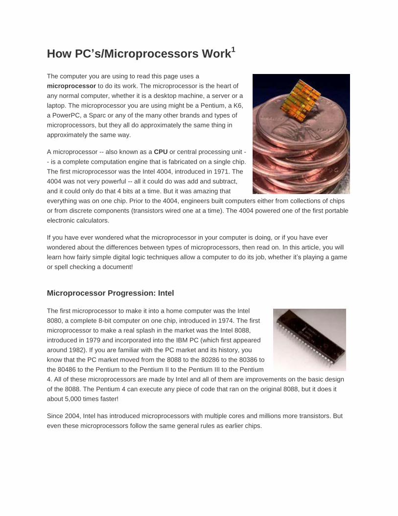
A microprocessor -- also known as a CPU or central processing unit -
- is a complete computation engine that is fabricated on a single chip.
The first microprocessor was the Intel 4004, introduced in 1971. The
4004 was not very powerful -- all it could do was add and subtract,
and it could only do that 4 bits at a time. But it was amazing that
everything was on one chip. Prior to the 4004, engineers built computers either from collections of chips
or from discrete components (transistors wired one at a time). The 4004 powered one of the first portable
electronic calculators.
If you have ever wondered what the microprocessor in your computer is doing, or if you have ever
wondered about the differences between types of microprocessors, then read on. In this article, you will
learn how fairly simple digital logic techniques allow a computer to do its job, whether it’s playing a game
or spell checking a document!
Microprocessor Progression: Intel
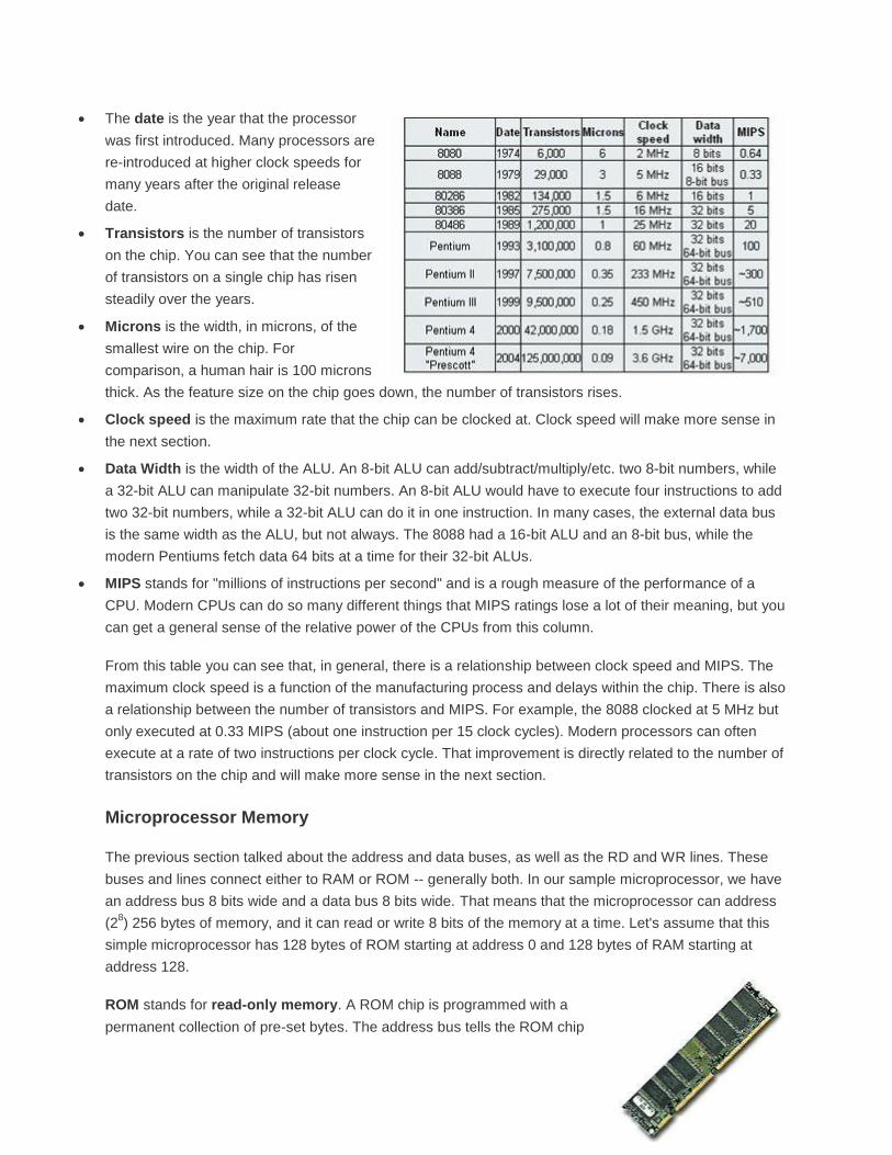
The first microprocessor to make it into a home computer was the Intel
8080, a complete 8-bit computer on one chip, introduced in 1974. The first
microprocessor to make a real splash in the market was the Intel 8088,
introduced in 1979 and incorporated into the IBM PC (which first appeared
around 1982). If you are familiar with the PC market and its history, you
know that the PC market moved from the 8088 to the 80286 to the 80386 to
the 80486 to the Pentium to the Pentium II to the Pentium III to the Pentium
4. All of these microprocessors are made by Intel and all of them are improvements on the basic design
of the 8088. The Pentium 4 can execute any piece of code that ran on the original 8088, but it does it
about 5,000 times faster!
Since 2004, Intel has introduced microprocessors with multiple cores and millions more transistors. But
even these microprocessors follow the same general rules as earlier chips.
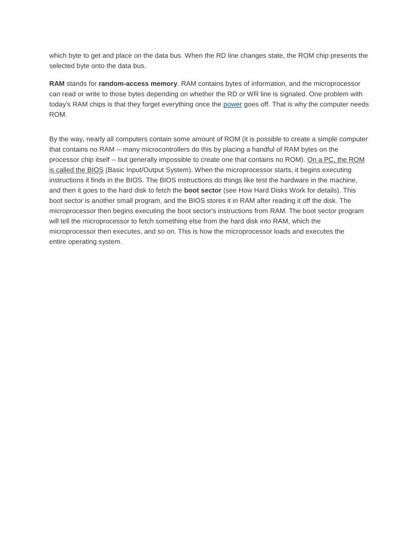
The date is the year that the processor
was first introduced. Many processors are
re-introduced at higher clock speeds for
many years after the original release
date.
Transistors is the number of transistors
on the chip. You can see that the number
of transistors on a single chip has risen
steadily over the years.
Microns is the width, in microns, of the
smallest wire on the chip. For
comparison, a human hair is 100 microns
thick. As the feature size on the chip goes down, the number of transistors rises.
Clock speed is the maximum rate that the chip can be clocked at. Clock speed will make more sense in
the next section.
Data Width is the width of the ALU. An 8-bit ALU can add/subtract/multiply/etc. two 8-bit numbers, while
a 32-bit ALU can manipulate 32-bit numbers. An 8-bit ALU would have to execute four instructions to add
two 32-bit numbers, while a 32-bit ALU can do it in one instruction. In many cases, the external data bus
is the same width as the ALU, but not always. The 8088 had a 16-bit ALU and an 8-bit bus, while the
modern Pentiums fetch data 64 bits at a time for their 32-bit ALUs.
MIPS stands for "millions of instructions per second" and is a rough measure of the performance of a
CPU. Modern CPUs can do so many different things that MIPS ratings lose a lot of their meaning, but you
can get a general sense of the relative power of the CPUs from this column.
From this table you can see that, in general, there is a relationship between clock speed and MIPS. The
maximum clock speed is a function of the manufacturing process and delays within the chip. There is also
a relationship between the number of transistors and MIPS. For example, the 8088 clocked at 5 MHz but
only executed at 0.33 MIPS (about one instruction per 15 clock cycles). Modern processors can often
execute at a rate of two instructions per clock cycle. That improvement is directly related to the number of
transistors on the chip and will make more sense in the next section.
Microprocessor Memory
The previous section talked about the address and data buses, as well as the RD and WR lines. These
buses and lines connect either to RAM or ROM -- generally both. In our sample microprocessor, we have
an address bus 8 bits wide and a data bus 8 bits wide. That means that the microprocessor can address
(28) 256 bytes of memory, and it can read or write 8 bits of the memory at a time. Let's assume that this
simple microprocessor has 128 bytes of ROM starting at address 0 and 128 bytes of RAM starting at
address 128.
ROM stands for read-only memory. A ROM chip is programmed with a
permanent collection of pre-set bytes. The address bus tells the ROM chip
which byte to get and place on the data bus. When the RD line changes state, the ROM chip presents the
selected byte onto the data bus.
RAM stands for random-access memory. RAM contains bytes of information, and the microprocessor
can read or write to those bytes depending on whether the RD or WR line is signaled. One problem with
today's RAM chips is that they forget everything once the power goes off. That is why the computer needs
ROM.
By the way, nearly all computers contain some amount of ROM (it is possible to create a simple computer
that contains no RAM -- many microcontrollers do this by placing a handful of RAM bytes on the
processor chip itself -- but generally impossible to create one that contains no ROM). On a PC, the ROM
is called the BIOS (Basic Input/Output System). When the microprocessor starts, it begins executing
instructions it finds in the BIOS. The BIOS instructions do things like test the hardware in the machine,
and then it goes to the hard disk to fetch the boot sector (see How Hard Disks Work for details). This
boot sector is another small program, and the BIOS stores it in RAM after reading it off the disk. The
microprocessor then begins executing the boot sector's instructions from RAM. The boot sector program
will tell the microprocessor to fetch something else from the hard disk into RAM, which the
microprocessor then executes, and so on. This is how the microprocessor loads and executes the
entire operating system.
Processor History Details2 Pictures Only
1969: Four-Phase Systems AL1 The AL1 was an 8-bit bit slice chip containing eight registers and an ALU It was designed by Lee Boysel in 1969 At the time, it formed part of a nine-chip, 24-bit CPU with three AL1s, but it was later called a microprocessor when, in response to 1990s litigation by Texas Instruments, a demonstration system was constructed where a single AL1 formed part of a courtroom demonstration computer system, together with RAM, ROM, and an input-output device
1971: Pico/GI PICO1/GI250 In 1971 Pico Electronics and General Instrument (GI) introduced their first collaboration in ICs, a complete single chip calculator IC for the Monroe/Litton Royal Digital III calculator. This chip could also arguably lay claim to be one of the first microprocessors or microcontrollers having ROM, RAM and a RISC instruction set on-chip. The layout for the four layers of the PMOS process was hand drawn at x500 scale on mylar film, a significant task at the time given the complexity of the chip.
1971: Intel 4004 The 4004 was Intel's first microprocessor. This breakthrough invention powered the Busicom calculator and paved the way for embedding intelligence in inanimate objects as well as the personal computer.
1972: Intel 8008 The 8008 was twice as powerful as the 4004. A 1974 article in Radio Electronics referred to a device called the Mark-8 which used the 8008. The Mark-8 is known as one of the first computers for the home --one that by today's standards was difficult to build, maintain and operate.
1974: Intel 8080 The 8080 became the brains of the first personal computer--the Altair, allegedly named for a destination of the Starship Enterprise from the Star Trek television show. Computer hobbyists could purchase a kit for the Altair for $395. Within months, it

sold tens of thousands, creating the first PC back orders in history.
1974: Texas Instruments TMS1000
1974: National Semiconductor "Pace" 16Bit
1975: Motorola 6502
1976: Zilog Z80

1978: Intel 8086-8088 A pivotal sale to IBM's new personal computer division made the 8088 the brains of IBM's new hit product--the IBM PC. The 8088's success propelled Intel into the ranks of the Fortune 500, and Fortune magazine named the company one of the "Business Triumphs of the Seventies."
1979: Motorola 68000
1981: HP 32 bit
1982: Intel 80286 The 80286, originally known as the 80286, was the first Intel processor that could run all the software written for its predecessor. This software compatibility remains a hallmark of Intel's family of microprocessors. Within 6 years of its release, an estimated 15 million 80286-based personal computers were installed around the world.
1985: Intel 80386 The Intel386™ microprocessor featured 275,000 transistors--more than 100times as many as the original 4004. It was a 32-bit chip and was "multi tasking," meaning it could run multiple programs at the same time.
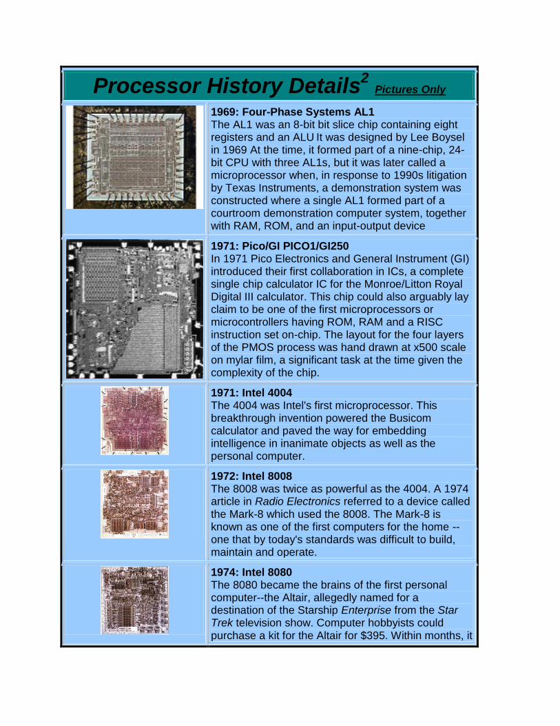
1989: Intel 80486 The 80486 processor generation really meant you go from a command-level computer into point-and-click computing. "I could have a color computer for the first time and do desktop publishing at a significant speed," recalls technology historian David K. Allison of the Smithsonian's National Museum of American History. The 80486 processor was the first to offer a built-in math coprocessor, which speeds up computing because it offloads complex math functions from the central processor.
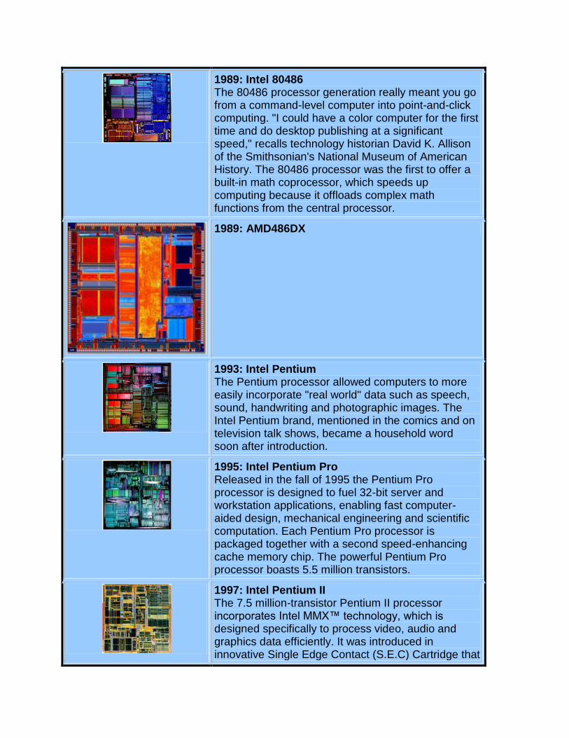
1989: AMD486DX
1993: Intel Pentium The Pentium processor allowed computers to more easily incorporate "real world" data such as speech, sound, handwriting and photographic images. The Intel Pentium brand, mentioned in the comics and on television talk shows, became a household word soon after introduction.
1995: Intel Pentium Pro Released in the fall of 1995 the Pentium Pro processor is designed to fuel 32-bit server and workstation applications, enabling fast computer-aided design, mechanical engineering and scientific computation. Each Pentium Pro processor is packaged together with a second speed-enhancing cache memory chip. The powerful Pentium Pro processor boasts 5.5 million transistors.
1997: Intel Pentium II The 7.5 million-transistor Pentium II processor incorporates Intel MMX™ technology, which is designed specifically to process video, audio and graphics data efficiently. It was introduced in innovative Single Edge Contact (S.E.C) Cartridge that
also incorporated a high-speed cache memory chip. With this chip, PC users can capture, edit and share digital photos with friends and family via the Internet; edit and add text, music or between-scene transitions to home movies; and, with a video phone, send video over standard phone lines and the Internet.
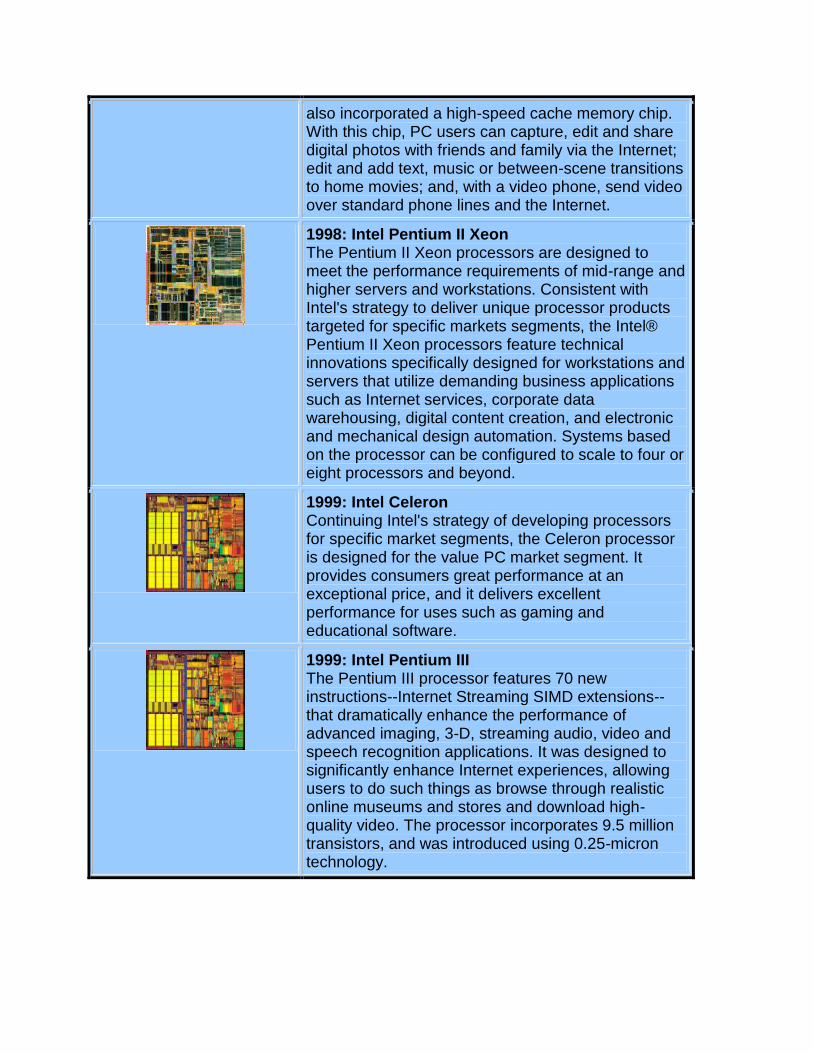
1998: Intel Pentium II Xeon The Pentium II Xeon processors are designed to meet the performance requirements of mid-range and higher servers and workstations. Consistent with Intel's strategy to deliver unique processor products targeted for specific markets segments, the Intel® Pentium II Xeon processors feature technical innovations specifically designed for workstations and servers that utilize demanding business applications such as Internet services, corporate data warehousing, digital content creation, and electronic and mechanical design automation. Systems based on the processor can be configured to scale to four or eight processors and beyond.
1999: Intel Celeron Continuing Intel's strategy of developing processors for specific market segments, the Celeron processor is designed for the value PC market segment. It provides consumers great performance at an exceptional price, and it delivers excellent performance for uses such as gaming and educational software.
1999: Intel Pentium III The Pentium III processor features 70 new instructions--Internet Streaming SIMD extensions-- that dramatically enhance the performance of advanced imaging, 3-D, streaming audio, video and speech recognition applications. It was designed to significantly enhance Internet experiences, allowing users to do such things as browse through realistic online museums and stores and download high-quality video. The processor incorporates 9.5 million transistors, and was introduced using 0.25-micron technology.

1999: Intel Pentium III Xeon™ The Pentium III Xeon processor extends Intel's offerings to the workstation and server market segments, providing additional performance for e-Commerce applications and advanced business computing. The processors incorporate the Pentium III processor's 70 SIMD instructions, which enhance multimedia and streaming video applications. The Pentium III Xeon processor's advance cache technology speeds information from the system bus to the processor, significantly boosting performance. It is designed for systems with multiprocessor configurations.
2000: Intel Pentium 4 Users of Pentium 4 processor-based PCs can create professional-quality movies; deliver TV-like video via the Internet; communicate with real-time video and voice; render 3D graphics in real time; quickly encode music for MP3 players; and simultaneously run several multimedia applications while connected to the Internet. The processor debuted with 42 million transistors and circuit lines of 0.18 microns. Intel's first microprocessor, the 4004, ran at 108 kilohertz (108,000 hertz), compared to the Intel® Pentium® 4 processor's initial speed of 1.5 gigahertz (1.5 billion hertz). If automobile speed had increased similarly over the same period, you could now drive from San Francisco to New York in about 13 seconds.
2001: Intel Xeon The Xeon processor is targeted for high-performance and mid-range, dual-processor workstations, dual and multi-processor server configurations coming in the future. The platform offers customers a choice of operating systems and applications, along with high performance at affordable prices. Intel Xeon processor-based workstations are expected to achieve performance increases between 30 and 90 percent over systems featuring Pentium III Xeon™ processors depending on applications and configurations. The processor is based on the Intel NetBurst™ architecture, which is designed to deliver the processing power needed for video and audio applications, advanced Internet technologies, and complex 3-D graphics.
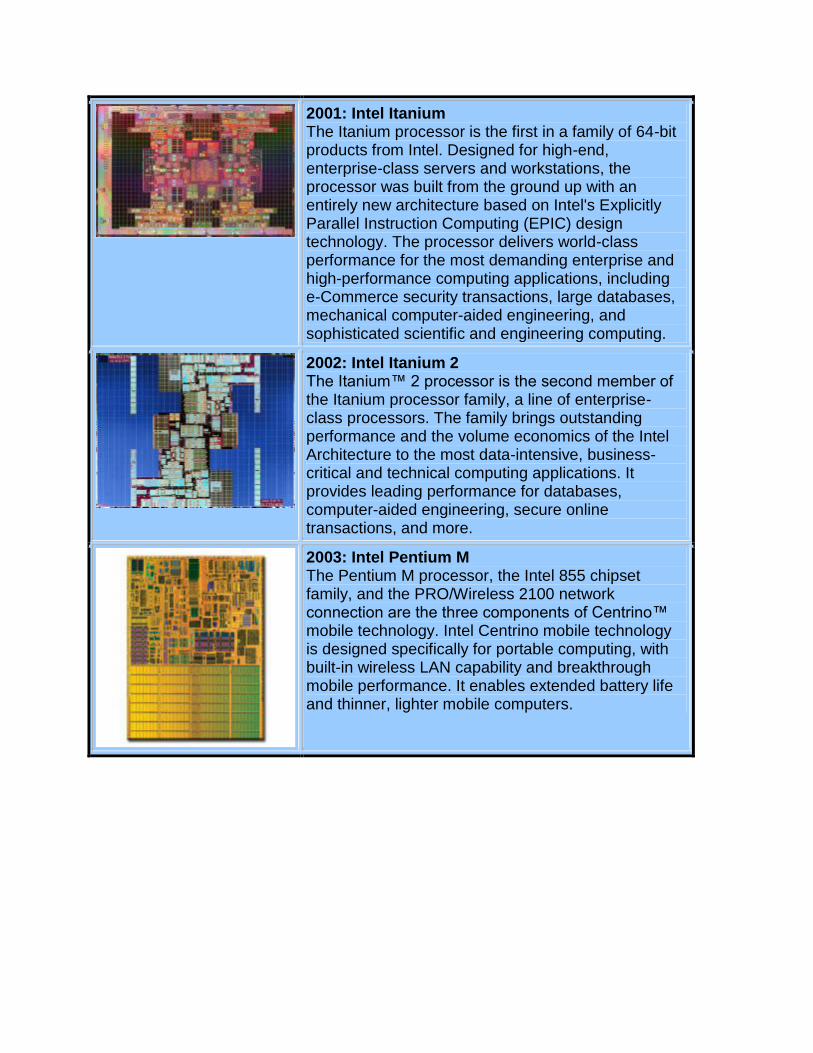
2001: Intel Itanium The Itanium processor is the first in a family of 64-bit products from Intel. Designed for high-end, enterprise-class servers and workstations, the processor was built from the ground up with an entirely new architecture based on Intel's Explicitly Parallel Instruction Computing (EPIC) design technology. The processor delivers world-class performance for the most demanding enterprise and high-performance computing applications, including e-Commerce security transactions, large databases, mechanical computer-aided engineering, and sophisticated scientific and engineering computing.
2002: Intel Itanium 2 The Itanium™ 2 processor is the second member of the Itanium processor family, a line of enterprise-class processors. The family brings outstanding performance and the volume economics of the Intel Architecture to the most data-intensive, business-critical and technical computing applications. It provides leading performance for databases, computer-aided engineering, secure online transactions, and more.
2003: Intel Pentium M The Pentium M processor, the Intel 855 chipset family, and the PRO/Wireless 2100 network connection are the three components of Centrino™ mobile technology. Intel Centrino mobile technology is designed specifically for portable computing, with built-in wireless LAN capability and breakthrough mobile performance. It enables extended battery life and thinner, lighter mobile computers.
The Computer Mouse3
Mice first broke onto the public stage with the introduction of the Apple Macintosh in 1984, and since then
they have helped to completely redefine the way we use computers.
Every day of your computing life, you reach out for your mouse whenever you want to move your cursor
or activate something. Your mouse senses your motion and your clicks and sends them to the computer
so it can respond appropriately.
In this article we'll take the cover off of this important part of the human-machine interface and see exactly
what makes it tick.
Evolution of the Computer Mouse
It is amazing how simple and effective a mouse is, and it is also amazing how long it took mice to become
a part of everyday life. Given that people naturally point at things -- usually before they speak -- it is
surprising that it took so long for a good pointing device to develop. Although originally conceived in the
1960s, a couple of decades passed before mice became mainstream.
In the beginning, there was no need to point because computers used crude interfaces like teletype
machines or punch cards for data entry. The early text terminals did nothing more than emulate a teletype
(using the screen to replace paper), so it was many years (well into the 1960s and early 1970s) before
arrow keys were found on most terminals. Full screen editors were the first things to take real advantage
of the cursor keys, and they offered humans the first way to point.
Light pens were used on a variety of machines as a pointing device for many years, and graphics
tablets, joy sticks and various other devices were also popular in the 1970s. None of these really took off
as the pointing device of choice, however.
When the mouse hit the scene -- attached to the Mac, it was an immediate success. There is something
about it that is completely natural. Compared to a graphics tablet, mice are extremely inexpensive and
they take up very little desk space. In the PC world, mice took longer to gain ground, mainly because of a
lack of support in the operating system. Once Windows 3.1 made Graphical User Interfaces (GUIs) a
standard, the mouse became the PC-human interface of choice very quickly.
Inside a Mouse
The main goal of any mouse is to translate the motion of your hand into signals that the computer can
use. Let's take a look inside a track-ball mouse to see how it works:
1. A ball inside the mouse touches the desktop and rolls when the mouse moves. The underside of the
mouse's logic board: The exposed portion of the ball touches the desktop.
2. Two rollers inside the mouse touch the ball. One of the rollers is oriented so that it detects motion in the
X direction, and the other is oriented 90 degrees to the first roller so it detects motion in the Y direction.
When the ball rotates, one or both of these rollers rotate as well. The following image shows the two white
rollers on this mouse: The rollers that touch the ball and detect X and Y motion
3. The rollers each connect to a shaft, and the shaft spins a disk with holes in it. When a roller rolls, its shaft
and disk spin. The following image shows the disk: A typical optical encoding disk: This disk has 36
holes around its outer edge.
4. On either side of the disk there is an infrared LED and an infrared sensor. The holes in the disk break
the beam of light coming from the LED so that the infrared sensor sees pulses of light. The rate of the
pulsing is directly related to the speed of the mouse and the distance it travels. A close-up of one of the
optical encoders that track mouse motion: There is an infrared LED (clear) on one side of the disk
and an infrared sensor (red) on the other.
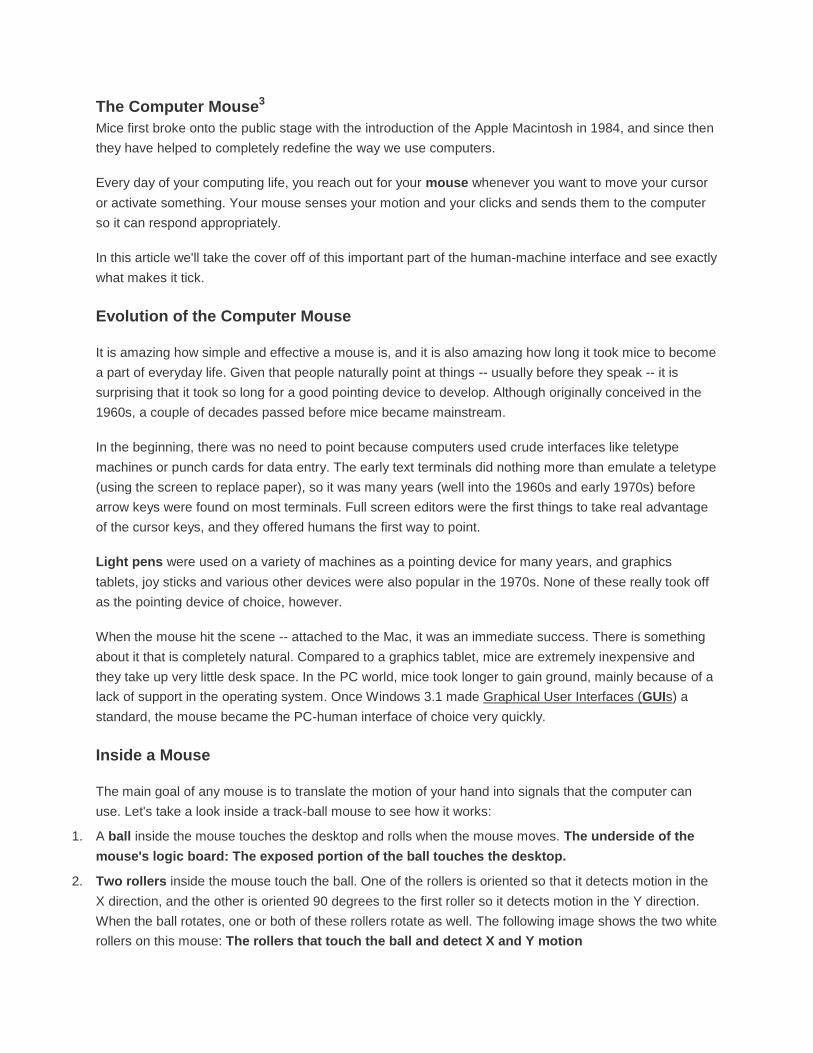
5. An on-board processor chip reads the pulses from the infrared sensors and turns them into binary data
that the computer can understand. The chip sends the binary data to the computer through the mouse's
cord.
The logic section of a mouse is dominated by an encoder chip, a small processor that reads the pulses coming from the infrared sensors and turns them into bytes sent to the computer. You can also see the two buttons that detect clicks (on either side of the wire connector).
In this optomechanical arrangement, the disk moves mechanically, and an optical system counts pulses
of light. On this mouse, the ball is 21 mm in diameter. The roller is 7 mm in diameter. The encoding disk
has 36 holes. So if the mouse moves 25.4 mm (1 inch), the encoder chip detects 41 pulses of light.
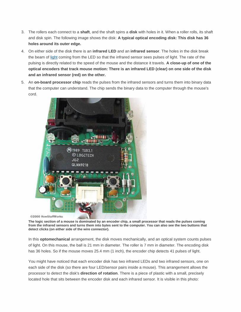
You might have noticed that each encoder disk has two infrared LEDs and two infrared sensors, one on
each side of the disk (so there are four LED/sensor pairs inside a mouse). This arrangement allows the
processor to detect the disk's direction of rotation. There is a piece of plastic with a small, precisely
located hole that sits between the encoder disk and each infrared sensor. It is visible in this photo:
A close-up of one of the optical encoders that track mouse motion: Note the piece of plastic between the infrared sensor (red) and the encoding disk.
This piece of plastic provides a window through which the infrared sensor can "see." The window on one
side of the disk is located slightly higher than it is on the other -- one-half the height of one of the holes in
the encoder disk, to be exact. That difference causes the two infrared sensors to see pulses of light at
slightly different times. There are times when one of the sensors will see a pulse of light when the other
does not, and vice versa.
Optical Mice
Developed by Agilent Technologies and introduced to the world in late 1999, the optical mouse actually
uses a tiny camera to take thousands of pictures every second.
Able to work on almost any surface without a mouse pad, most optical mice use a small, red light-emitting
diode (LED) that bounces light off that surface onto a complimentary metal-oxide semiconductor (CMOS)
sensor. In addition to LEDs, a recent innovation are laser-based optical mice that detect more surface
details compared to LED technology. This results in the ability to use a laser-based optical mouse on
even more surfaces than an LED mouse.
Here's how the sensor and other parts of an optical mouse work together:
The CMOS sensor sends each image to a digital signal processor (DSP) for analysis.
The DSP detects patterns in the images and examines how the patterns have moved since the previous
image.

Based on the change in patterns over a sequence of images, the DSP determines how far the mouse has
moved and sends the corresponding coordinates to the computer.
The computer moves the cursor on the screen based on the coordinates received from the mouse. This
happens hundreds of times each second, making the cursor appear to move very smoothly.
Optical mice have several benefits over track-ball mice:
No moving parts means less wear and a lower chance of failure.
There's no way for dirt to get inside the mouse and interfere with the tracking sensors.
Increased tracking resolution means a smoother response.
They don't require a special surface, such as a mouse pad.
Connecting Computer Mice
Most mice on the market today use a USB connector to attach to your computer. USB is a standard way
to connect all kinds of peripherals to your computer, including printers, digital cameras, keyboards and
mice.
Monitor Display Technology4
Often referred to as a monitor when packaged in a separate case, the display is the most-used output
device on a computer. The display provides instant feedback by showing you text and graphic images as
you work or play.
Most desktop displays use liquid crystal display (LCD); some older monitors use cathode ray tube (CRT)
technology (they are big and bulky compared to the thin LCD monitors), while nearly all portable
computing devices such as laptops incorporate LCD technology. Because of their slimmer design and
lower energy consumption, monitors using LCD technology (also called flat panel or flat screen displays)
are replacing the venerable CRT on most desktops. A new technology which will replace the LCD
monitors is LED, or light-emitting diodes; these tend to be brighter and have better contrast – but are also
more expensive.
Resolution refers to the number of individual dots of color, known as pixels, contained on a display.
Resolution is expressed by identifying the number of pixels on the horizontal axis (rows) and the number
on the vertical axis (columns), such as 800x600. Resolution is affected by a number of factors, including
the size of the screen.
As monitor sizes have increased over the years, display standards and resolutions have changed.
Common Display Standards and Resolutions
XGA (Extended Graphics Array) = 1024x768
SXGA (Super XGA) = 1280x1024
UXGA (Ultra XGA) = 1600x1200
QXGA (Quad XGA) = 2048x1536
WXGA (Wide XGA) = 1280x800
WSXGA+ (Wide SXGA plus) = 1680x1050
WUXGA (Wide Ultra XGA) = 1920x1200
WQHD = 2560 x 1440
WQXGA = 2560 x 1600
QSXGA = 2560 x 2048
In addition to the screen size, display standards and resolutions are related to something called
the aspect ratio. Next, we'll discuss what an aspect ratio is and how screen size is measured.
Aspect Ratio and Viewable Area
Two measures describe the size of your display: the aspect ratio and the screen size. Historically,
computer displays, like most televisions, have had an aspect ratio of 4:3. This means that the ratio of the
width of the display screen to the height is 4 to 3.

For widescreen LCD monitors, the aspect ratio is 16:9 (or sometimes 16:10 or 15:9). Widescreen LCD
displays are useful for viewing DVDmovies in widescreen format, playing games and displaying multiple
windows side by side.High definition television (HDTV) also uses a widescreen aspect ratio.
All types of displays include a projection surface, commonly referred to as the screen. Screen sizes are
normally measured in inches from one corner to the corner diagonally across from it. This diagonal
measuring system actually came about because the early television manufacturers wanted to make the
screen size of their TVs sound more impressive.
Interestingly, the way in which the screen size is measured for CRT and LCD monitors is different. For
CRT monitors, screen size is measured diagonally from outside edges of the display casing. In other
words, the exterior casing is included in the measurement as seen below.
For LCD monitors, screen size is measured diagonally from the inside of the beveled edge. The
measurement does not include the casing as indicated in the image below.
LCD screen size
Because of the differences in how CRT and LCD monitors
are measured, a 17-inch LCD display is comparable to a
19-inch CRT display. For a more accurate representation of
a CRT's size, find out its viewable screen size. This is the
measurement of a CRT display without its outside casing.
Popular screen sizes are 15, 17, 19 and 21 inches.
Notebook screen sizes are smaller, typically ranging from
12 to 17 inches. As technologies improve in both desktop
and notebook displays, even larger screen sizes are
becoming available. For professional applications, such as
medical imaging or public information displays, some LCD
monitors are 40 inches or larger!
Obviously, the size of the display directly affects resolution. The same pixel resolution is sharper on a
smaller monitor and fuzzier on a larger monitor because the same number of pixels is spread out over a
larger number of inches. An image on a 21-inch monitor with an 800x600 resolution will not appear nearly
as sharp as it would on a 15-inch display at 800x600.
Analog and DVI Connections
To display information on a monitor, your computer sends the monitor a signal. The signal can be in
analog or digital format.
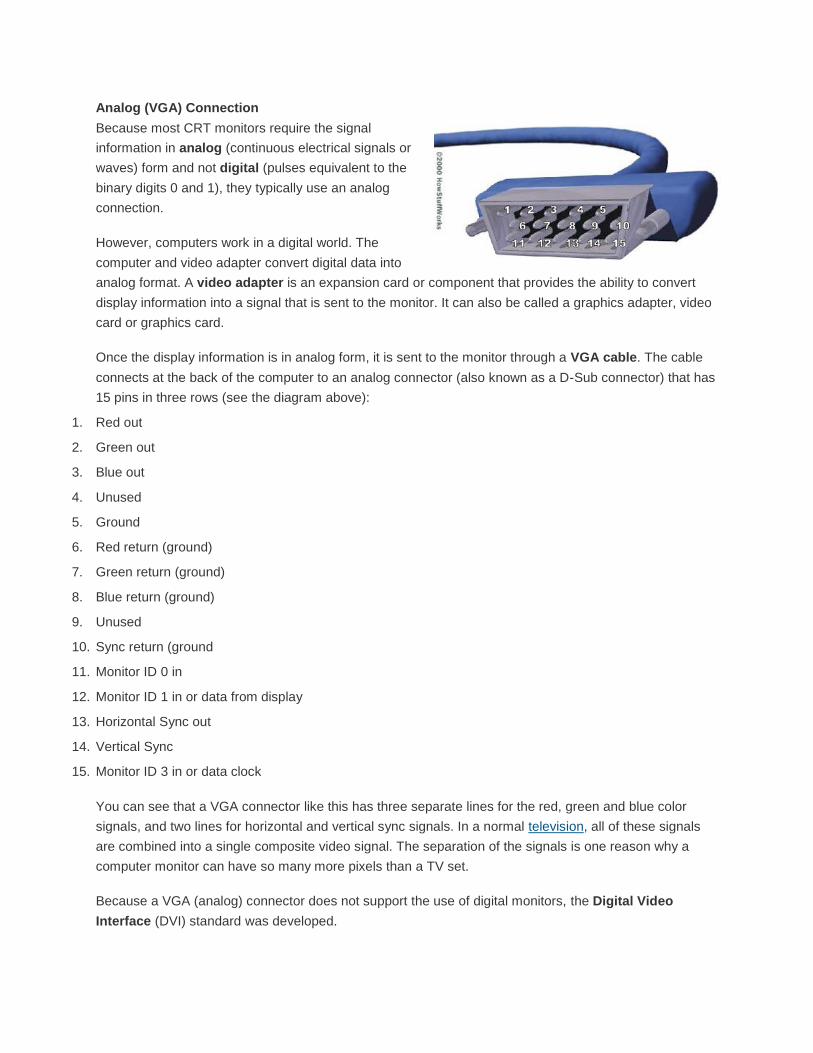
Analog (VGA) Connection
Because most CRT monitors require the signal
information in analog (continuous electrical signals or
waves) form and not digital (pulses equivalent to the
binary digits 0 and 1), they typically use an analog
connection.
However, computers work in a digital world. The
computer and video adapter convert digital data into
analog format. A video adapter is an expansion card or component that provides the ability to convert
display information into a signal that is sent to the monitor. It can also be called a graphics adapter, video
card or graphics card.
Once the display information is in analog form, it is sent to the monitor through a VGA cable. The cable
connects at the back of the computer to an analog connector (also known as a D-Sub connector) that has
15 pins in three rows (see the diagram above):
1. Red out
2. Green out
3. Blue out
4. Unused
5. Ground
6. Red return (ground)
7. Green return (ground)
8. Blue return (ground)
9. Unused
10. Sync return (ground
11. Monitor ID 0 in
12. Monitor ID 1 in or data from display
13. Horizontal Sync out
14. Vertical Sync
15. Monitor ID 3 in or data clock
You can see that a VGA connector like this has three separate lines for the red, green and blue color
signals, and two lines for horizontal and vertical sync signals. In a normal television, all of these signals
are combined into a single composite video signal. The separation of the signals is one reason why a
computer monitor can have so many more pixels than a TV set.
Because a VGA (analog) connector does not support the use of digital monitors, the Digital Video
Interface (DVI) standard was developed.
DVI Connection
DVI keeps data in digital form from the computer to the monitor. There's no need to convert data from
digital information to analog information. LCD monitors work in a digital mode and support the DVI format.
(Although, some also accept analog information, which is then converted to digital format.) At one time, a
digital signal offered better image quality compared to analog technology. However, analog signal
processing technology has improved over the years and the difference in quality is now minimal.
The DVI specification is based on Silicon Image's Transition Minimized Differential Signaling (TMDS)
and provides a high-speed digital interface. A transmitter on the video adapter sends the digital
information to a receiver in the monitor. TMDS takes the signal from the video adapter, determines
the resolution andrefresh rate that the monitor is using, and spreads the signal out over the available
bandwidth to optimize the data transfer from computer to monitor.
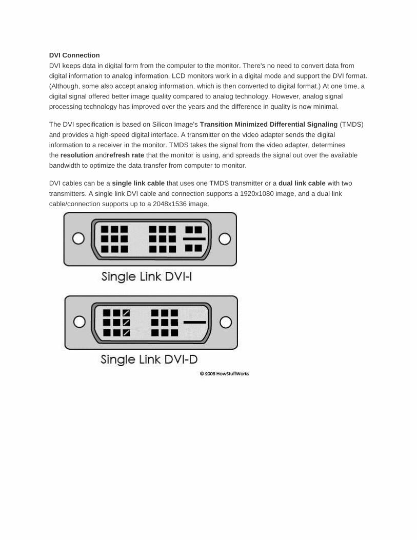
DVI cables can be a single link cable that uses one TMDS transmitter or a dual link cable with two
transmitters. A single link DVI cable and connection supports a 1920x1080 image, and a dual link
cable/connection supports up to a 2048x1536 image.
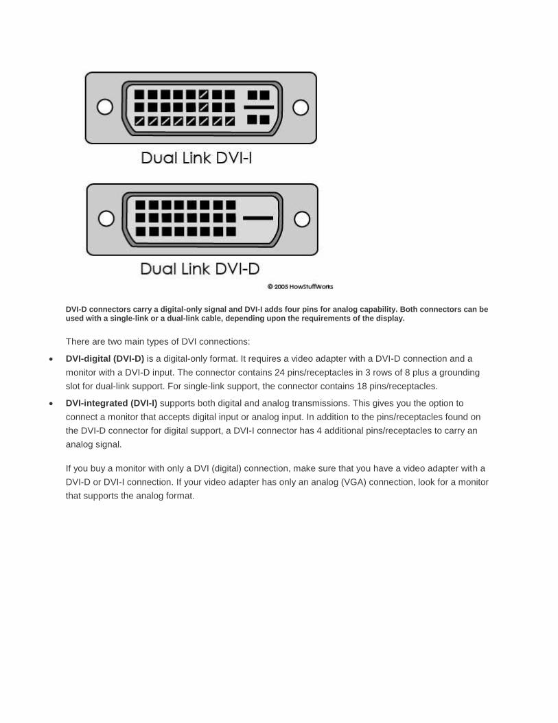
DVI-D connectors carry a digital-only signal and DVI-I adds four pins for analog capability. Both connectors can be used with a single-link or a dual-link cable, depending upon the requirements of the display.
There are two main types of DVI connections:
DVI-digital (DVI-D) is a digital-only format. It requires a video adapter with a DVI-D connection and a
monitor with a DVI-D input. The connector contains 24 pins/receptacles in 3 rows of 8 plus a grounding
slot for dual-link support. For single-link support, the connector contains 18 pins/receptacles.
DVI-integrated (DVI-I) supports both digital and analog transmissions. This gives you the option to
connect a monitor that accepts digital input or analog input. In addition to the pins/receptacles found on
the DVI-D connector for digital support, a DVI-I connector has 4 additional pins/receptacles to carry an
analog signal.
If you buy a monitor with only a DVI (digital) connection, make sure that you have a video adapter with a
DVI-D or DVI-I connection. If your video adapter has only an analog (VGA) connection, look for a monitor
that supports the analog format.

References
1 How Stuff Works website. “How PC’s Work”. http://www.howstuffworks.com/microprocessor.htm
2. Microprocessor Hall of Fame website.
http://www.tayloredge.com/museum/processor/processorhistory.html
3. How Stuff Works website. “How Mice Work”. http://www.howstuffworks.com/mouse.htm
4. How Stuff Works website. “How Monitors Work”. http://www.howstuffworks.com/monitor1.htm
Top Related