


Languages
Pages
Legal

High Power Transmitter
Module WTX-14014546_47-70-ES-35
40 to 50 Watt, 70 dB Gain
Ku-Band ODU
Operation & Maintenance Manual

Mitec telecom inc.Designers and manufacturers of telecom and wireless products
9000 Trans Canada,PointeClaire, Quebec, CanadaH9R 5Z8
OPERATION AND MAINTENANCE MANUAL Preliminary Released
REVISION RECORDRevision ECN # Description Date Approved
0 Engineering Release. 31 Aug 04
CM Approval TITLE:
WTX14014542_43_4470ES35High Power Transmitter Module
This document contains information proprietary to Mitec telecom inc., or its affiliates, or to a third party to which Mitec telecom inc. may have a legal obligation to protect such information from unauthorized disclosure, use, or duplication. Any disclosure, use, or duplication of this document or of any of the information contained herein is expressly prohibited except as Mitec telecom inc. may otherwise agree in writing.
Designer: Marina Lissianskaia Date: 31 Aug 04
Technical Writer: Colleen Strunga Date: 31 Aug 04 DOCUMENT NO.18537001MA
REV 0
PAGE 1 OF 33

mitec Table of Contents
Table of
Contents
1INTRODUCTION................................................................................11.1Receiving and Inspection..........................................................................................2
1.1.1Equipment Damage or Loss.....................................................................................21.1.2Return of Equipment................................................................................................2
1.2 Preparing for Installation........................................................................................31.1.3Safety Precautions....................................................................................................3
2 INSTALLATION & OVERVIEW........................................................41.3General Description...................................................................................................4
1.4Specifications..............................................................................................................42.1.1General Considerations............................................................................................6
1.5Basic Mechanical Characteristics............................................................................62.1.2External View of the Transmitter Module..............................................................62.1.3Connections and Mounting Hardware.....................................................................7
1.6Assembly and Installation.........................................................................................72.1.4Lifting the Transmitter Module into Position and Temporary Attachment .........72.1.5Securing the Transmitter Module............................................................................8
1.7Functional Overview.................................................................................................82.1.6General......................................................................................................................82.1.7IF/RF Conversion and Amplification......................................................................92.1.8Monitor and Control.................................................................................................92.1.9Internal Power Distribution Reference..................................................................10
3 OPERATION.................................................................................111.8 Procedure................................................................................................................11
3.1.1.1Interface..................................................................................................................12
Rev 0 i
Table of Contents mitec
4 MAINTENANCE.............................................................................131.9Preventive Maintenance..........................................................................................13
4.1.1Procedure................................................................................................................134.1.2Transmitter Module Cooling System Preventive Maintenance ..........................134.1.3Performance Check................................................................................................144.1.4Troubleshooting......................................................................................................154.1.5Outof Warranty Repair.........................................................................................15
APPENDIX A.......................................................................................1Drawings & Schematic Diagrams.................................................................................1
APPENDIX B.......................................................................................1Spare Parts......................................................................................................................1
List of Tables
TABLE 1 –SPECIFICATIONS.............................................................4
TABLE 1 –SPECIFICATIONS.............................................................4
FIGURE 1 – RECOMMENDED DISTANCE FOR MOUNTING ON THE HUB.....................................................................................................8
FIGURE 2 SYSTEM BLOCK DIAGRAM............................................9
TABLE 2 –CONNECTOR PIN ASSIGNMENTS.................................12
TABLE 2 –CONNECTOR PIN ASSIGNMENTS.................................12
FIGURE 3 – COOLING FAN REPLACEMENT..................................14
TABLE 3 RECOMMENDED CORRECTIVE ACTIONS...................15
TABLE 3 RECOMMENDED CORRECTIVE ACTIONS...................15
FIGURE 4 – OUTLINE DRAWING.......................................................3
List of Figures
Figure 1 – Recommended Distance for Mounting on the Hub ...............................................
ii Rev 0

mitec Table of Contents
Figure 2 System Block Diagram ............................................................................................ Figure 3 – Cooling Fan Replacement ....................................................................................... Figure 4 – Outline Drawing................................................................................................A3
Rev 0 iii

mitec Preface
Preface
Scope
This document covers the installation, operation, and maintenance of the WTX14014542_43_4470ES35 High Power Transmitter Module. It contains information intended for engineers, technicians and operators working with the transmitter module.
To make inquiries, or to report errors of fact or omission in this document, please contact Mitec telecom inc. at (514) 6949000.
IMPORTANT
Important information concerning the operation and care of this product, as well as safety of authorized operators is highlighted throughout this document by one of the following labels:
NOTE Indicates a reminder, a special consideration, or additional information that is important to know.
CAUTION! Identifies situations that have the potential to cause equipment damage.
WARNING!! Identifies hazardous situations that have the potential to cause equipment damage as well as serious personal injury.
Rev 0 P-1

mitec Introduction
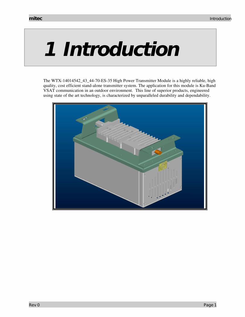
1 IntroductionThe WTX14014542_43_4470ES35 High Power Transmitter Module is a highly reliable, high quality, cost efficient standalone transmitter system. The application for this module is KuBand VSAT communication in an outdoor environment. This line of superior products, engineered using state of the art technology, is characterized by unparalleled durability and dependability.
Rev 0 Page 1
Introduction mitec
1.1Receiving and Inspection
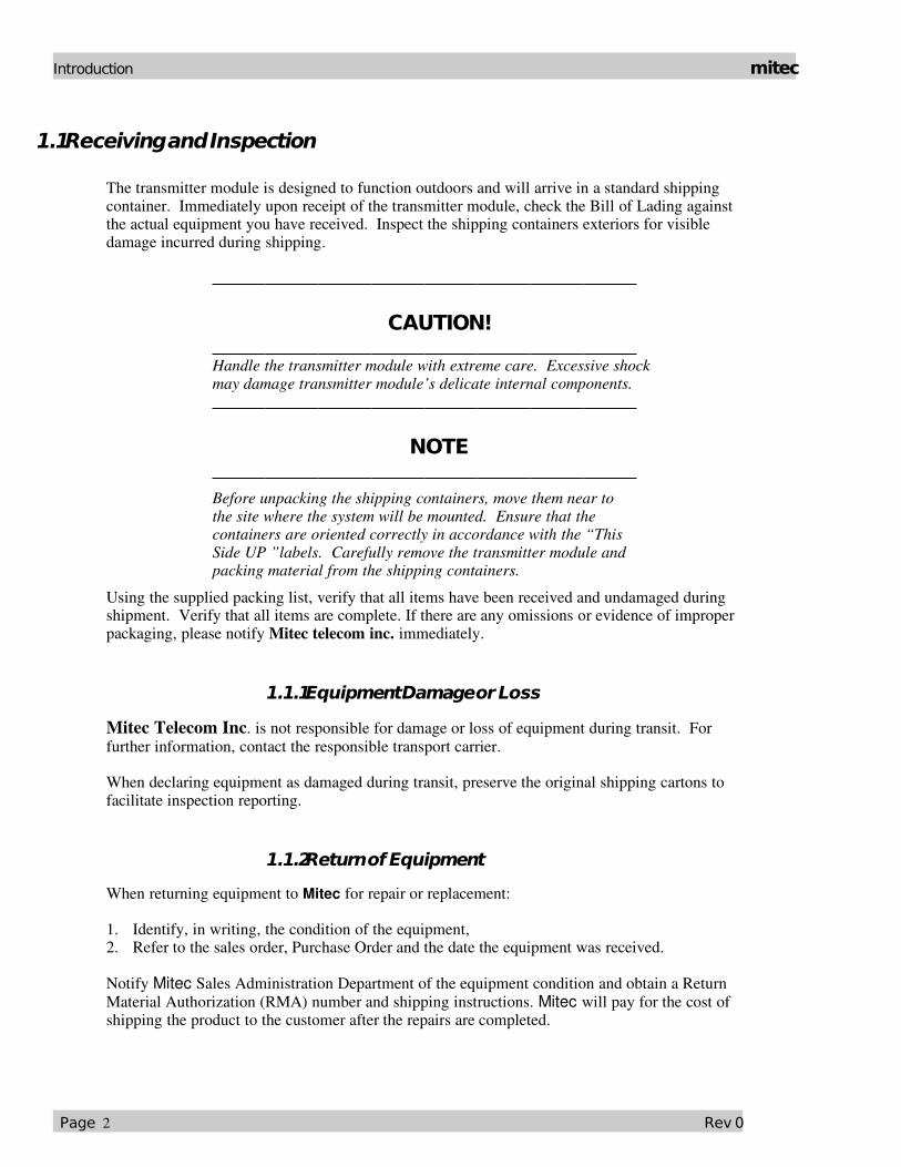
The transmitter module is designed to function outdoors and will arrive in a standard shipping container. Immediately upon receipt of the transmitter module, check the Bill of Lading against the actual equipment you have received. Inspect the shipping containers exteriors for visible damage incurred during shipping.
CAUTION! Handle the transmitter module with extreme care. Excessive shock may damage transmitter module’s delicate internal components.
NOTE Before unpacking the shipping containers, move them near to the site where the system will be mounted. Ensure that the containers are oriented correctly in accordance with the “This Side UP ”labels. Carefully remove the transmitter module and packing material from the shipping containers.
Using the supplied packing list, verify that all items have been received and undamaged during shipment. Verify that all items are complete. If there are any omissions or evidence of improper packaging, please notify Mitec telecom inc. immediately.
1.1.1Equipment Damage or Loss
Mitec Telecom Inc. is not responsible for damage or loss of equipment during transit. For further information, contact the responsible transport carrier.
When declaring equipment as damaged during transit, preserve the original shipping cartons to facilitate inspection reporting.
1.1.2Return of Equipment
When returning equipment to Mitec for repair or replacement:
1. Identify, in writing, the condition of the equipment,2. Refer to the sales order, Purchase Order and the date the equipment was received.
Notify Mitec Sales Administration Department of the equipment condition and obtain a Return Material Authorization (RMA) number and shipping instructions. Mitec will pay for the cost of shipping the product to the customer after the repairs are completed.
Page 2 Rev 0
mitec Introduction
NOTE Do not return any equipment without an RMA number. This is important for prompt, efficient handling of the returned equipment and of the associated complaint.
1.2 Preparing for Installation
Before attempting to install or use the transmitter module, we recommend that you first familiarize yourself with the product by reading through this manual. Understanding the operation of the system will reduce the possibility of incorrect installation, thereby causing damage or injury to yourself or others.
The transmitter module must be installed in accordance with the conditions and recommendations contained in the following sections.
When you are ready to begin your installation, use the information in Chapter 2 (Installation) as a guide for making all the required electrical connections.
1.1.3Safety Precautions
Carelessness or mishandling of the transmitter module may damage the unit causing serious injury to yourself or others. Please adhere to the following:
WARNING!! This unit is equipped with an AC power cord and plug. Do not tamper with, or attempt to reconfigure, the cord or plug supplied with the unit, as this can:♦ result in personal injury♦ void the warranty♦ cause damage to the units or related equipment.
Rev 0 Page 3
Installation & Overview mitec
2 Installation & Overview
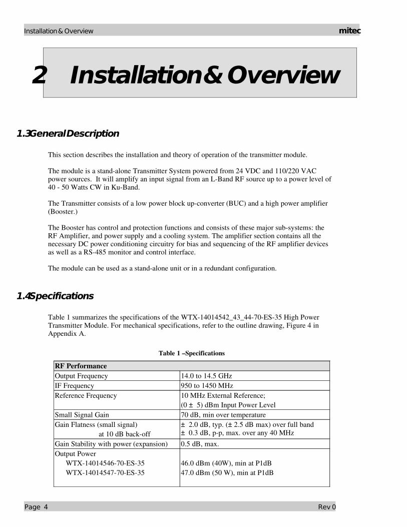
1.3General Description
This section describes the installation and theory of operation of the transmitter module.
The module is a standalone Transmitter System powered from 24 VDC and 110/220 VAC power sources. It will amplify an input signal from an LBand RF source up to a power level of 40 50 Watts CW in KuBand.
The Transmitter consists of a low power block upconverter (BUC) and a high power amplifier (Booster.)
The Booster has control and protection functions and consists of these major subsystems: the RF Amplifier, and power supply and a cooling system. The amplifier section contains all the necessary DC power conditioning circuitry for bias and sequencing of the RF amplifier devices as well as a RS485 monitor and control interface.
The module can be used as a standalone unit or in a redundant configuration.
1.4Specifications
Table 1 summarizes the specifications of the WTX14014542_43_4470ES35 High PowerTransmitter Module. For mechanical specifications, refer to the outline drawing, Figure 4 in Appendix A.
Table 1 –Specifications
RF PerformanceOutput Frequency 14.0 to 14.5 GHzIF Frequency 950 to 1450 MHzReference Frequency 10 MHz External Reference;
(0 ± 5) dBm Input Power LevelSmall Signal Gain 70 dB, min over temperatureGain Flatness (small signal)
at 10 dB backoff± 2.0 dB, typ. (± 2.5 dB max) over full band± 0.3 dB, pp, max. over any 40 MHz
Gain Stability with power (expansion) 0.5 dB, max.Output Power
WTX1401454670ES35WTX1401454770ES35
46.0 dBm (40W), min at P1dB47.0 dBm (50 W), min at P1dB
Page 4 Rev 0
mitec Installation & Overview
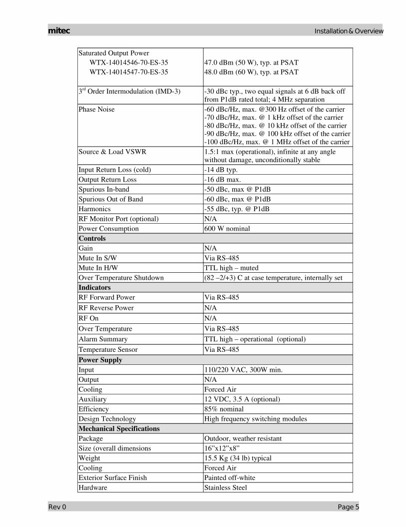
Saturated Output PowerWTX1401454670ES35WTX1401454770ES35
47.0 dBm (50 W), typ. at PSAT48.0 dBm (60 W), typ. at PSAT
3rd Order Intermodulation (IMD3) 30 dBc typ., two equal signals at 6 dB back off from P1dB rated total; 4 MHz separation
Phase Noise 60 dBc/Hz, max. @300 Hz offset of the carrier70 dBc/Hz, max. @ 1 kHz offset of the carrier80 dBc/Hz, max. @ 10 kHz offset of the carrier90 dBc/Hz, max. @ 100 kHz offset of the carrier100 dBc/Hz, max. @ 1 MHz offset of the carrier
Source & Load VSWR 1.5:1 max (operational), infinite at any angle without damage, unconditionally stable
Input Return Loss (cold) 14 dB typ.Output Return Loss 16 dB max.Spurious Inband 50 dBc, max @ P1dBSpurious Out of Band 60 dBc, max @ P1dBHarmonics 55 dBc, typ. @ P1dBRF Monitor Port (optional) N/APower Consumption 600 W nominalControlsGain N/AMute In S/W Via RS485Mute In H/W TTL high – mutedOver Temperature Shutdown (82 –2/+3) C at case temperature, internally setIndicatorsRF Forward Power Via RS485RF Reverse Power N/ARF On N/AOver Temperature Via RS485Alarm Summary TTL high – operational (optional)Temperature Sensor Via RS485Power SupplyInput 110/220 VAC, 300W min.Output N/ACooling Forced AirAuxiliary 12 VDC, 3.5 A (optional)Efficiency 85% nominalDesign Technology High frequency switching modulesMechanical SpecificationsPackage Outdoor, weather resistantSize (overall dimensions 16”x12”x8”Weight 15.5 Kg (34 lb) typicalCooling Forced AirExterior Surface Finish Painted offwhiteHardware Stainless Steel
Rev 0 Page 5

Installation & Overview mitec
Oring SiliconeConnectorsIF Input Ntype femaleRF Output WR75 groovedRF Monitor N/AAC Input MS3102R2015P – 7 pins maleRS485 Interface MS3112E1412P – 12 pins femaleMarkings Labels permanent and legible
1 Mitec Part No & Revision Level2 Serial No.3 IF Input4 RF Output5 RS4856 AC Input
Environmental Operational StorageTemperature 400 to 550C 500C to 850CHumidity 5% to 95% at 400C 5% to 95% at 650CAltitude 10,000 ft AMSL 40,000 ft AMSLShock and Vibration Normal transport and handlingDrop N/A 1m in shipping containerReliabilityMTBF (mean time between failures 80,000 hours (fan reliability data is not included.
Fan must be replaced once every 2 years minimum.
2.1.1General Considerations
The module shall meet all specifications over full bandwidth and under all environmental conditions when terminated with a load of VSWR at 1.5:1 unless otherwise specified. All RF specifications shall be met within five minutes after applying DC power, except gain flatness, which shall be met after a warmup period of ten minutes. During the warmup period, the module shall not exhibit any alarm or require an RF mute input signal to reset any alarm/fault latches.
1.5Basic Mechanical Characteristics
2.1.2External View of the Transmitter Module
The physical external dimensions of the transmitter module are shown in Figure 4 and Table 1. All inputs and outputs are shown in Figure 4.
Page 6 Rev 0
mitec Installation & Overview
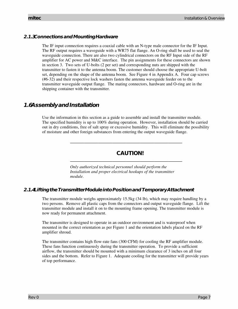
2.1.3Connections and Mounting Hardware
The IF input connection requires a coaxial cable with an Ntype male connector for the IF Input. The RF output requires a waveguide with a WR75 flat flange. An Oring shall be used to seal the waveguide connection. There are also two cylindrical connectors on the RF Input side of the RF amplifier for AC power and M&C interface. The pin assignments for these connectors are shown in section 3. Two sets of Ubolts (2 per set) and corresponding nuts are shipped with the transmitter to fasten it to the antenna boom. The customer should choose the appropriate Ubolt set, depending on the shape of the antenna boom. See Figure 4 in Appendix A. Four cap screws (#632) and their respective lock washers fasten the antenna waveguide feeder on to the transmitter waveguide output flange. The mating connectors, hardware and Oring are in the shipping container with the transmitter.
1.6Assembly and Installation
Use the information in this section as a guide to assemble and install the transmitter module. The specified humidity is up to 100% during operation. However, installation should be carried out in dry conditions, free of salt spray or excessive humidity. This will eliminate the possibility of moisture and other foreign substances from entering the output waveguide flange.
CAUTION! Only authorized technical personnel should perform the Installation and proper electrical hookups of the transmitter module.
2.1.4Lifting the Transmitter Module into Position and Temporary Attachment
The transmitter module weighs approximately 15.5kg (34 lb), which may require handling by a two persons. Remove all plastic caps from the connectors and output waveguide flange. Lift the transmitter module and install it on to the mounting frame opening. The transmitter module is now ready for permanent attachment.
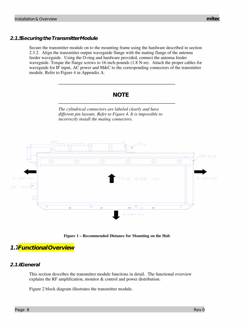
The transmitter is designed to operate in an outdoor environment and is waterproof when mounted in the correct orientation as per Figure 1 and the orientation labels placed on the RF amplifier shroud.
The transmitter contains high flowrate fans (300 CFM) for cooling the RF amplifier module. These fans function continuously during the transmitter operation. To provide a sufficient airflow, the transmitter should be mounted with a minimum clearance of 3 inches on all four sides and the bottom. Refer to Figure 1. Adequate cooling for the transmitter will provide years of top performance.
Rev 0 Page 7
Installation & Overview mitec
2.1.5Securing the Transmitter Module
Secure the transmitter module on to the mounting frame using the hardware described in section 2.3.2. Align the transmitter output waveguide flange with the mating flange of the antenna feeder waveguide. Using the Oring and hardware provided, connect the antenna feeder waveguide. Torque the flange screws to 16 inchpounds (1.8 Nm). Attach the proper cables for waveguide for IF input, AC power and M&C to the corresponding connectors of the transmitter module. Refer to Figure 4 in Appendix A.
NOTE The cylindrical connectors are labeled clearly and have different pin layouts. Refer to Figure 4. It is impossible to incorrectly install the mating connectors.
Figure 1 – Recommended Distance for Mounting on the Hub
1.7Functional Overview
2.1.6General
This section describes the transmitter module functions in detail. The functional overview explains the RF amplification, monitor & control and power distribution.
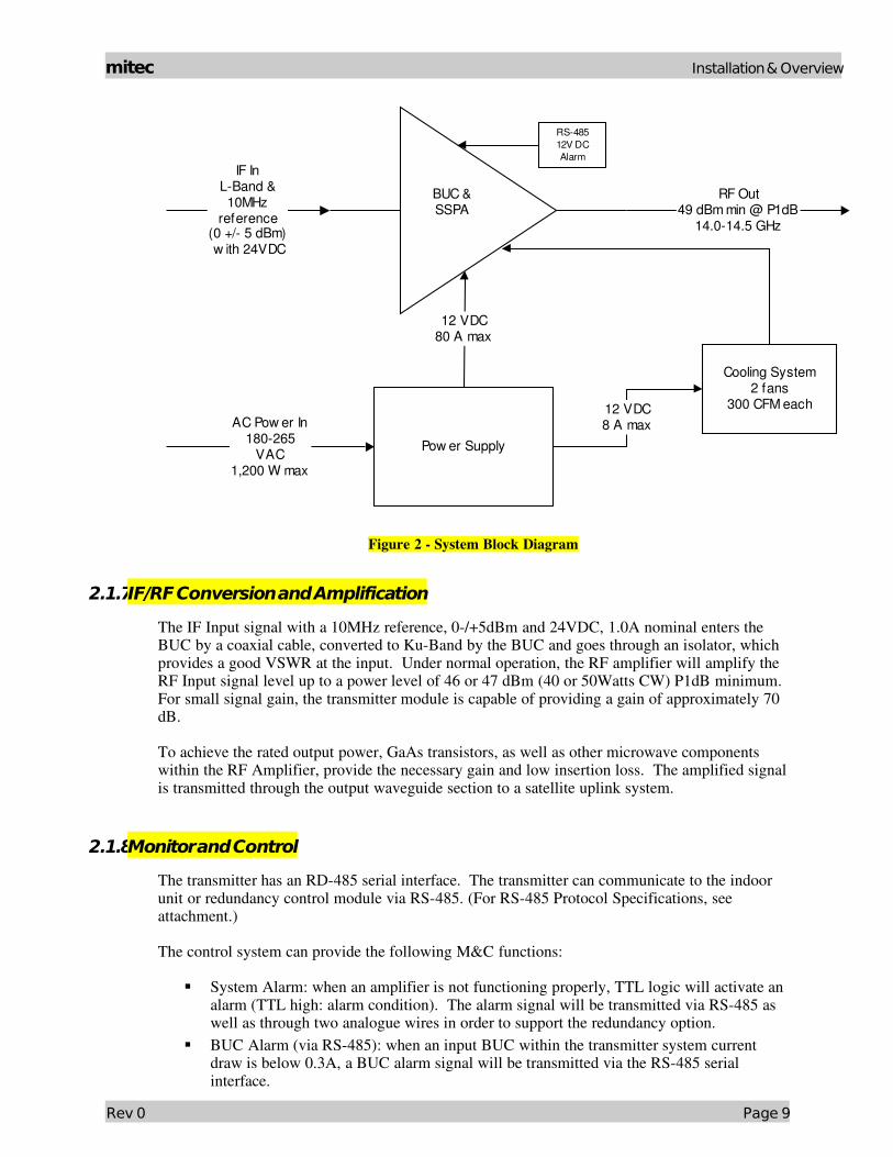
Figure 2 block diagram illustrates the transmitter module.
Page 8 Rev 0
mitec Installation & Overview
12 VDC80 A max
BUC &SSPA
Pow er Supply
Cooling System2 fans
300 CFM each
IF InLBand &10MHz
reference(0 +/ 5 dBm) w ith 24VDC
RF Out49 dBm min @ P1dB
14.014.5 GHz
AC Pow er In180265
VAC1,200 W max
12 VDC8 A max
RS48512V DCAlarm
Figure 2 System Block Diagram
2.1.7IF/RF Conversion and Amplification
The IF Input signal with a 10MHz reference, 0/+5dBm and 24VDC, 1.0A nominal enters the BUC by a coaxial cable, converted to KuBand by the BUC and goes through an isolator, which provides a good VSWR at the input. Under normal operation, the RF amplifier will amplify the RF Input signal level up to a power level of 46 or 47 dBm (40 or 50Watts CW) P1dB minimum. For small signal gain, the transmitter module is capable of providing a gain of approximately 70 dB.
To achieve the rated output power, GaAs transistors, as well as other microwave components within the RF Amplifier, provide the necessary gain and low insertion loss. The amplified signal is transmitted through the output waveguide section to a satellite uplink system.
2.1.8Monitor and Control
The transmitter has an RD485 serial interface. The transmitter can communicate to the indoor unit or redundancy control module via RS485. (For RS485 Protocol Specifications, see attachment.)
The control system can provide the following M&C functions:
System Alarm: when an amplifier is not functioning properly, TTL logic will activate an alarm (TTL high: alarm condition). The alarm signal will be transmitted via RS485 as well as through two analogue wires in order to support the redundancy option.
BUC Alarm (via RS485): when an input BUC within the transmitter system current draw is below 0.3A, a BUC alarm signal will be transmitted via the RS485 serial interface.
Rev 0 Page 9

Installation & Overview mitec
Mute Control (via RS485) Mute Control (via hardware line): TTL high level signal will mute a transmitter Output Power Monitoring: 15 dB dynamic range (via RS485) Base Plate Temperature Monitoring (via RS485)
The SSPA can also provide 12VDC (2A max) at the same connector to supply DC power for redundancy control.
2.1.9Internal Power Distribution Reference
The SSPA operates from power source of 110 VAC to 265 VAC, 47 Hz to 63 Hz and will consume 600Watts maximum.
CAUTION! There is an internal slow blowing fuse installed in the power supply module in order to protect the entire system from over current.
The power supply converts the incoming AC voltage into two separate DC voltages. The DC voltages are regulated to ensure isolation and stability. The module provides:
12 VDC, 50 A maximum to the RF amplifier circuits 12 VDC, 4 A maximum to the cooling system fan. Refer to Figure 2
Page 10 Rev 0

mitec Maintenance
3 OperationThis chapter describes the verification of the operation and control of the transmitter module. It shall be performed by authorized personnel prior to maintenance and/or repair.
1.8 Procedure
Verify that the installation procedure described in Chapter 2 was completed. A complete physical check of the customer’s system is suggested.
WARNING! The output power available at the output waveguide flange is extremely hazardous. Under no circumstances should be transmitter be operated without the waveguide feed or a high power load attached. Do not operate this equipment in the presence of flammable gases or fumes. Failure to observe this precaution will result in personal injury. Safe and careful installation of this transmitter will eliminate the possibility of accidents and provide years of top performance.
Verify the antenna feed waveguide connection is properly done before the transmitter is energized.
NOTE The transmitter module can withstand any source or load VSWR. However, the transmitter module will meet all specification requirements only if the source/load VSWR is sufficient. Refer to Section 2.2
Normal operation is not possible if the antenna feeder VSWR is greater than 1.5:1.
Turn ON the power and allow a warm up period of twenty minutes before operating the transmitter module. This will assure stable gain and power. The transmitter module can function with a coupler when a direct measurement of the output power is made.
Rev 0 Page 11
Maintenance mitec
CAUTION! It is strongly recommended not to exceed 20 dBm maximum RF Input level. The RF amplifier will be in deep saturation if overdriven. RF performance will degrade significantly, and proper operation is not possible. This operational condition is the survival mode for the transmitter module. Never exceed the maximum safe RIF Input level of 10dBm (100 mW) or permanent damage to the transmitter module may result.
Verify the status of the System Fail signal from the M&C interface using the RS485 protocol. (Protocol description is attached to this manual.)
3.1.1.1 Interface
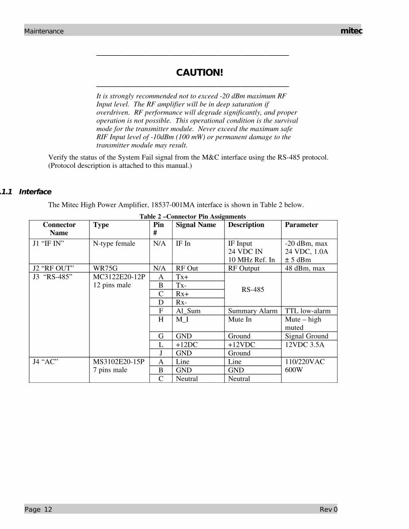
The Mitec High Power Amplifier, 18537001MA interface is shown in Table 2 below.Table 2 –Connector Pin Assignments
Connector Name
Type Pin #
Signal Name Description Parameter
J1 “IF IN” Ntype female N/A IF In IF Input24 VDC IN10 MHz Ref. In
20 dBm, max 24 VDC, 1.0A± 5 dBm
J2 “RF OUT” WR75G N/A RF Out RF Output 48 dBm, maxJ3 “RS485” MC3122E2012P
12 pins maleA Tx+B TxC Rx+D Rx
RS485
F Al_Sum Summary Alarm TTL lowalarmH M_I Mute In Mute – high
mutedG GND Ground Signal GroundL +12DC +12VDCJ GND Ground
12VDC 3.5A
J4 “AC” MS3102E2015P 7 pins male
A Line LineB GND GNDC Neutral Neutral
110/220VAC 600W
Page 12 Rev 0
mitec Maintenance
4 MaintenanceThis chapter contains information on how to maintain, troubleshoot and repair the transmitter module. The transmitter module is extremely reliable, requiring very little preventive maintenance, or repair. Should there be a malfunction, this chapter also contains technical information to help diagnose basic failures.
1.9Preventive Maintenance
4.1.1Procedure
WARNING! Shut down the transmitter module before disassembly and remove all cables and connectors. Failure to observe this precaution may result in personal injury or death. This includes the removal of any RF power originating from other system components.
When the transmitter module is in the hot standby mode in a redundant system, switch it to the operation mode at least once every three months. Make sure the fan is running while in operation mode.
When the transmitter module is in the cold standby mode in a redundant system, switch it to the operation mode at least once every three months. Make sure the fan is running while in operation mode.
4.1.2Transmitter Module Cooling System Preventive
Maintenance
Preventive maintenance is limited to checking the performance of the transmitter module cooling system. No electrical or mechanical adjustments are required for normal operation.
The fan is the least reliable item in the transmitter module. Wearing of the fan bearings will cause the RPM to drop and will create a higher than average heatsink temperature. It is recommended to replace the fan after 2 years of operation.
Rev 0 Page 13
Maintenance mitec
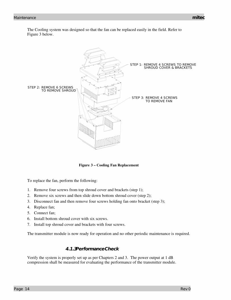
The Cooling system was designed so that the fan can be replaced easily in the field. Refer to Figure 3 below.
STEP 1: REMOVE 4 SCREWS TO REMOVE SHROUD COVER & BRACKETS
STEP 3: REMOVE 4 SCREWS
STEP 2: REMOVE 6 SCREWS
TO REMOVE FAN
TO REMOVE SHROUD
Figure 3 – Cooling Fan Replacement
To replace the fan, perform the following:
1. Remove four screws from top shroud cover and brackets (step 1);2. Remove six screws and then slide down bottom shroud cover (step 2);3. Disconnect fan and then remove four screws holding fan onto bracket (step 3);4. Replace fan;5. Connect fan;6. Install bottom shroud cover with six screws.7. Install top shroud cover and brackets with four screws.
The transmitter module is now ready for operation and no other periodic maintenance is required.
4.1.3Performance Check
Verify the system is properly set up as per Chapters 2 and 3. The power output at 1 dB compression shall be measured for evaluating the performance of the transmitter module.
Page 14 Rev 0

mitec Maintenance
It is recommended to measure the following parameters for ensuring that the transmitter module is in good working condition:
Gain and Gain flatness RF load VSWR and RF source VSWR TwoTone Intermodulation Distortion Return Loss at connectors J1 and J2 of the TRANSMITTER MODULE
Using a Source and an IF input signal level within the small signal region of the transmitter module, measure the power level at connectors J1 and J2. See Table 2. Plot the swept response on a test data sheet. From the plot, determine gain and gain flatness.
With an IF Input signal level within the small signal region of the transmitter module, measure the VSWR (Return Loss) at connectors J1 and J2 See Table 2. Plot the swept return loss for both the IF Input and RF Output signals on a test data sheet. From the plot determine the return loss.
From the output power measurements determine P1dB. Record value on a test data sheet.
Measure the Twotone Intermodulation Suppression using two equal signals separated by 5 MHz. Record value on test data sheet.
4.1.4Troubleshooting
WARNING!! Cable connection and disconnection shall be done carefully to avoid physical damage to the cables and connectors, which may cause intermittent problems in the future.
Use Table 1 to quickly isolate a fault within the transmitter module. If the transmitter module is defective, notify Mitec and follow the process detailed in section 1.1.2.
Symptom ActionFails performance test Check power source, RF source, cabling and connectors. Check
for clogged fan and debris in heatsink fins. Clean thoroughly. If fan is worn, replace fan. If correct, transmitter module is defective. Return transmitter module to Mitec.
Table 3 Recommended Corrective Actions
4.1.5Out-of Warranty Repair
A nonwarranty and outofwarranty repair service is available from Mitec for a nominal charge. The customer is responsible for paying the cost of shipping the SSPA both to and from Mitec for these repairs.
Rev 0 Page 15


mitec Appendix A
Appendix A
Drawings & Schematic Diagrams
18537001MA Outline Drawing
Rev 0 A - 1

mitec Appendix F
B- 2 Rev 0

mitec Appendix A
13.28 in [337.3 mm]
12.18 in [309.3 mm]
0.5
9 in
[1
5.1
mm
]
3.8
8 in
[9
8.6
mm
]
1.81 in [45.8 mm]
9.5
5 in
[2
42
.4 m
m]
11
.88
in
[3
01
.8 m
m]
POWER & M/CMS-3102R20-15P
0.41 in [10.3 mm]
0.36 in [9.2 mm]FLANGE TO MOUNTING HOLE CENTER
2.0
0 in
[5
0.8
mm
]
4.3
5 in
[1
10
.4 m
m]
6.10 in [154.9 mm]
7.51 in [190.8 mm]
RF OUTWR 75
14.00 in [355.5 mm]
IF INF-TYPE FEMALE
Figure 4 – Outline Drawing
Rev 0 A - 3

mitec Appendix F
B- 4 Rev 0
mitec Appendix B
Appendix B
Spare Parts
Appendix B contains a table of recommended spare parts for onhand replacement. The following sheet can be copied and used as a fax form to order the required spare parts. Please make sure to include all identifying information to facilitate the processing of your order. The order may also be sent via email or regular mail delivery, at the following address.
Mitec telecom inc.9000 Trans Canada Blvd.Pointe Claire, Quebec, CanadaH9R 5Z8
Fax: (514)6943814Email: [email protected]
For additional information, please contact our customer service department at:(514)6949000 or 18007243911
Rev 0 B - 1

mitec Appendix F
B- 2 Rev 0

mitec Appendix B
Mitec telecom inc.designers and manufacturers of telecom & wireless productsISO 9001 Certified
Spare Parts Order FormWTX14014542_43_4470ES35
High Power TransmitterModule
From:
Place By: Signature:Telephone:Fax Email:
Part Description Part Number Quantity Unit Price*
Line Total*
* To be completed by Mitec Sales Department
Fax to: Customer Service (514)6943814
Rev 0 B - 3
Top Related