


Languages
Pages
Legal


Hexapodinno
18-DOF Robot Instruction Manual
Version 1.17

i
Trademark
Innovati®, , and BASIC Commander®, are registered trademarks of Innovati Inc. InnoBASIC™ and cmdBUS™
are trademarks of Innovati Inc.
Copyright ©2008-2009 by Innovati Inc. All rights reserved.
In view of unceasing improvement of products, this document and the product mentioned in this document are
subject to be changed by the company without notice. It is forbidden to reproduce and distribute any part or all of
the contents of the product without the written approval or authorization by the company.
Disclaimer
The user shall undertake all the risks in the applications where this product is used. The company shall not be liable
for any direct, indirect or consequential damages due to the use of the product including but not limited to the loss
of equipment, the loss of human safety and health and the loss of profit and reputation. The product of the company
shall not be used in life saving or any related instrument and equipment. Children under 14 shall not use this
product for any related experiment without being accompanied by adults.
Errata
We hope the users may regard this document as a lively and practical instruction manual. We have put
tremendous efforts in making this instruction manual complete and correct; however, there may be
unavoidable missing parts or errors. With a view to providing the user updated and complete information
in the instruction manual, we keep improving and supplement the contents of this instruction manual. If
you find any error in this manual, please contact us via the e-mail [email protected]. Any related
update information will be disclosed on our website. Please visit our website http://www.innovati.com.tw
for more updated information.

ii
Precautions
This kit comprises 2 modules, BASIC Commander® and Servo Runner A, each with respective
instructions for use and functions. Please refer to these for optimal effects.
When installing BASIC Commander® to the Command Board, make sure the input voltage is
within the 6-12V range, otherwise the module may burn.
The input voltage to the Servo Runner A must correspond to the voltage rating of the servomotor.
Servomotors provided in this kit are rated 4.8-6V; over or under voltage may cause unpredictable
results, even burning of the motor. Make absolutely sure of the correct voltage before connecting the
power supply.
The kit provides a total of 12 servomotors. When operated simultaneously, they consume a large
current; make sure the power supply or battery connecting to Servo Runner A is capable of providing
10A of current, so as to properly operate the kit. Insufficient current may cause unexpected results
and damage of the kit.
When using a battery power supply to the module, the voltage may lower after some while of
operation and cause abnormal actions of the kit. In such case, remove and fully charge the battery
before using again. If prolonged testing and operation is required, we suggest you use a power
supply unit to ensure uniform performance.
Prior to assembling the kit, install InnoBASIC™ Workshop as per the content of the CD; also make sure
that the PC communicates with BASIC Commander® via a USB Line connection, so that the entire
assembly can be accomplished.

iii
Table of Contents Part List ........................................................................................................................................................1
Tools ..............................................................................................................................................................4
Assembly Procedure ....................................................................................................................................5
Calibration Servomotors ...........................................................................................................................................5
Assemble the Leg Frames.........................................................................................................................................9
Connecting Top Board with Module ......................................................................................................................11
Fine-Tuning Initial value of Servomotor .................................................................................................17
Structure fine-tuning ...............................................................................................................................................17
Software fine-tuning ...............................................................................................................................................17
Perform Demonstrative Motions..............................................................................................................24

1
Part List Item Illustration Qt’y Specifications and instructions
Assembly Kit Parts
Main Board for
module
installation
2
PC body Main Board for accommodating parts of the 6-leg robot. Six protrusions are for connecting six leg kits. The center part is for placing different modules or power supply according to different needs.
Supporting Leg
6
The supporting leg is made of PC material and connects servomotor terminal with screws.
Aluminum Servo
Plate
18
For accommodating the servomotor; different holes are provided for connecting with another Aluminum Servo Plate or Aluminum U-plate with module installation board.
Aluminum U-plate
12
Provides connection with the Aluminum Servo Plate and movement space of the servomotor; it also provides connection with two Aluminum U-plates for different applications.
Servomotor
18
Servomotor provides for 180° rotation moves capable of simulating articulation behaviors; connections with signal, power and ground are required for the operation. Pay attention to wire polarity. Avoid having the servomotor sustained to a same movement for a long period of time, to prevent wearing the motor. Dimensions (LxWxH) 40.6mmx20.0mmx42.8mm

2
Weight: 73 g, Speed: 0.33 sec/60°
Torque: 7.4 kg/cm
Screw A
54 ISOT 3 x 8 mm
Screw B
12 ISOP 3 x 6 mm
Screw C
24 ISOP 3 x 18 mm
Screw D
72 TP1P 2 x 6 mm
Screw E
24 ISOP 2 x 5 mm
Screw F
30 ISOP 3 x 10 mm
Nut A
132 3 x 5.5 mm
Nut B
24 2 x 4 mm
Washer A
168 3 x 0.4 x 8 mm

3
Washer B
18 3 x 1 x 6 mm
Bearing
18 3 x 4 x 8 x 9.5 mm
Leg Sleeve
6
Black rubber sleeve, to be fit on
supporting leg, prevents leg
abrasion against the ground.
Hex post, Copper
6 55 mm
Module Kits
BC1
1
Innovati® BASIC
Commander®, capable of
storing programs and
controlling operations of
modules.
Servo Runner A
2
Innovati® Servo Runner A, for
controlling individual
servomotors.
Command Board
1
Used for installing BC1, with
spare cmdBUS™ allowing user
to make direct connections.
Servo Power Line
1
Connector for connecting 2
Servo Runner As at the same
time.

4
Command Board
Power Line
1
Cable for connecting
Command Board with Servo
Runner A’s Power Supply.
cmdBUS™
2
Control/signal cable for
connecting Servo Runner A to
Command Board.
USB Line
1
Links BC1 with PC, allowing
downloading of PC program to
BC1, or performing
communication in Debug
Mode.
Cable strap
30
Used for fixing wires, so that
they do not tangle or affect
motions unexpectedly during
the operation of the
servomotor.
1. Tools
Cross Screwdriver (2mm and 3 mm)
Long Nose Pliers
Screw Glue (selectively used between nut and Aluminum Plate joints, to prevent the nut from
loosening.)

5
2. Assembly Procedures
Calibrating Servomotors
Before starting installation, verify if the disk of servomotor is at the correct position;
if not, calibrate as follows:
Connect servomotor, Servo Runner A, Command Board, and power supply line
in the sequence as illustrated below.
※When the Command Board or Education Board shares the power supply with
Servo Runner A, please notice that the voltage of this kit should be 6V (please refer to
Notices). It is recommended to use a voltage regulator to ensure that the voltage is
within the safe range.
i. Connect the PC and BASIC Commander® with a USB line.
ii. Make sure that the power switch on the Command Board is set at the 0 position
(power off state). If it is not at the 0 position, please slide it to the 0 position.
iii. Connect the power line of the servomotor to the power supply. (Please make sure
that the voltage and current from the power supply are within the ranges
required by the servomotor. After the power cord is connected, the servomotor
may make a transient motion due to receiving a switch surge; this is normal.
While connecting the power line, please pay attention not to place your hands
within the space where the servomotor may move into to avoid being clamped.)
Connect to power with Servo Power Line. Mind the polarity. Connect “+” to the positive and “-” to the negative of the power supply.
Connect to Command Board with Education Board Power Line. Make sure to connect “+” to the positive and “-” to the negative of the power supply.
Connect all servomotors wServo Runner, as shown in the Fig. Pay attention to the pin position while makthe connection.
ith
ing
Connect to Command Board with cmbBus, and install BC1 to Command Board. Make sure the Power Switch on the Command Board is set to “0” (off).

iv. Start the InnoBASIC™ Workshop
v. Click the “Tools” item in the menu bar on the top.
Click the application in the InnoBASIC™ Workshop folder to start the InnoBASIC™ Workshop.
After clicking each item, a pull-down menu with more function items will be displayed. Please click the “Tools" item now.
vi. Click the “Motion Editor” in the pull-down menu (If a warning window appears,
it means that the BASIC Commander® is not correctly connected. Please check if
the USB line is connected or unplug and then plug it again to ensure a correct
connection. Exit the Motion Editor and then re-click this button.)
Click “Motion Editor” to start the Motion Editor.
If this message appears, it means that the USB line is not connected correctly.
6

1
vii. If the connection is correct, the message “Downloading servo manager” will be
displayed on the PC screen meaning that the program is being downloaded.
Please slide the power switch on the Command Board to the 1 position and wait
a moment.
viii. After the downloading is complete, a notification window will appear. Please
make sure that each servomotor has been connected correctly. After confirming
all the connections, please click “OK”. (If “Cancel” is clicked, the Motion Editor
will be closed. If there is any component is incorrectly connected at this moment,
please click “Cancel” to terminate the program.)
ix. Please pay attention not to place your hands within the space where the
servomotors may move into to avoid being clamped. Please check the checkbox
for activating the servomotors on the left side to move all the servomotors to
their central points. Please note that the number next to it should be 1500. If it is
not 1500, please click the number directly, enter the number 1500 and then click
“Enter”.
The message means that the program is being downloaded. Please do not remove the USB line.
The message appears for notifying the download is complete. Please make sure that each component has been connected correctly.
1
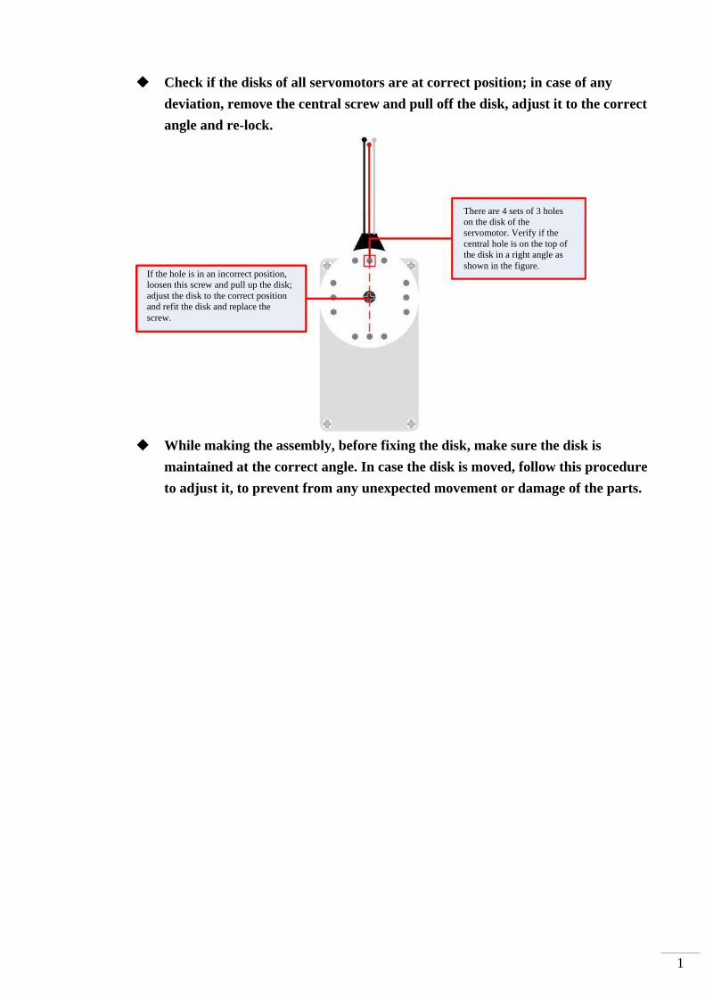
Check if the disks of all servomotors are at correct position; in case of any
deviation, remove the central screw and pull off the disk, adjust it to the correct
angle and re-lock.
While making the assembly, before fixing the disk, make sure the disk is
maintained at the correct angle. In case the disk is moved, follow this procedure
to adjust it, to prevent from any unexpected movement or damage of the parts.
There are 4 sets of 3 holes on the disk of the servomotor. Verify if the central hole is on the top of the disk in a right angle as shown in the figure.
If the hole is in an incorrect position, loosen this screw and pull up the disk; adjust the disk to the correct position and refit the disk and replace the screw.

2
A. Assemble the leg frames
i. Assemble the Aluminum U-plate: Place two Aluminum U-plates together as shown in
the figure. Use two sets of Screw B and Nut A to fix them together. Then insert two
bearings into the Aluminum U-plates from the outer surfaces.
ii. Place the two Aluminum Servo Plates as shown in the figure. Use 4 sets of Screw E
and Nut B to fix them together. (Please note that the holes for fixing the screws are
aligned in a way that the rightmost screw hole on one of the Servo Plates is fixed to
the center screw hole of the other Aluminum Servo Plate.)

3
iii. Use Screw F, Nut A, and Washer B to connect the bearing parts assembled in step ii
to the Aluminum Servo Plate.
iv. Install the servomotor in the Aluminum Servo Plate that is assembled in Step iii.
Please note that the location for the rotation disc is on the top of the bearing.
v. Use Screw A, Nut A and two Washer A to fix the servomotor on the Aluminum Servo
Plate. Note that it is required to insert a Washer A between Screw A and the
servomotor. Meanwhile, a Washer A should also be inserted between Nut A and the
Aluminum Plate.
The user can insert the lower half of the servomotor into the Aluminum Servo Plate first. Then adjust the Aluminum U-plate to allow the rotation disc to overlap.
The sequences from outside are Screw F, the bearing, Aluminum U-plate, Washer B, Aluminum Servo Plate and Screw A.

4
vi. Connect the Supporting Leg and the servomotor assembled in Step iv together and
fix them with Screw C and Nut A. In addition, insert a Washer A between Screw C
and the Servo Plate as well as between Nut A and the Supporting Leg.
vii. Repeat the above steps to complete the assembly of the components for other 5 legs.
B. Assembly of Body Components
i. Select either one of the main boards for module installation as the bottom plate.
According to the order from the bottom up, install the bearing on the extruded hole
and then connect and fix the component assembled in Step A. vi with Screw F, Nut A
and Washer B at the location for installing the bearing as describe in Step i.
5
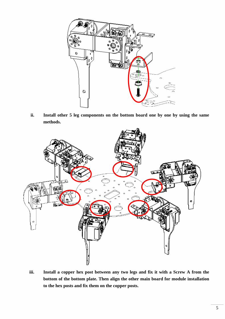
ii. Install other 5 leg components on the bottom board one by one by using the same
methods.
iii. Install a copper hex post between any two legs and fix it with a Screw A from the
bottom of the bottom plate. Then align the other main board for module installation
to the hex posts and fix them on the copper posts.

6
iv. Servo Runner A is fixed directly on the top plate with Screw F and Nut A through the
module. The user can select the 4 holes near the outer edge among the two sets of 8
continuously allocated holes for fixing the Servo Runner A. The installation of the
module can be performed according to the following figure by using a washer to
isolate the nut and the main board for module installation.
7
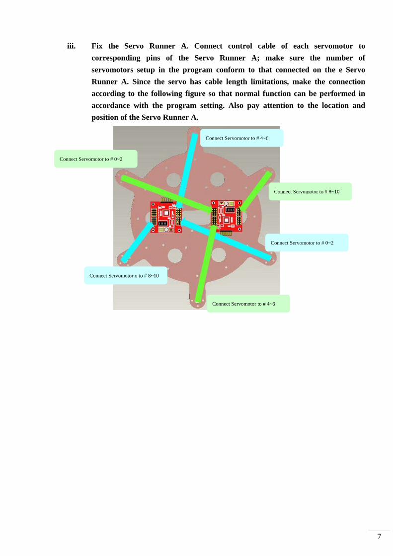
iii. Fix the Servo Runner A. Connect control cable of each servomotor to
corresponding pins of the Servo Runner A; make sure the number of
servomotors setup in the program conform to that connected on the e Servo
Runner A. Since the servo has cable length limitations, make the connection
according to the following figure so that normal function can be performed in
accordance with the program setting. Also pay attention to the location and
position of the Servo Runner A.
Connect Servomotor to # 0~2
Connect Servomotor to # 0~2
Connect Servomotor to # 4~6
Connect Servomotor to # 4~6
Connect Servomotor to # 8~10
Connect Servomotor o to # 8~10
8
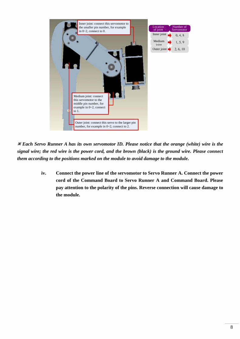
Each Servo Runner A has its own servomotor ID. Please notice that the orange (white) wire is the
signal wire; the red wire is the power cord, and the brown (black) is the ground wire. Please connect
them according to the positions marked on the module to avoid damage to the module.
iv. Connect the power line of the servomotor to Servo Runner A. Connect the power
cord of the Command Board to Servo Runner A and Command Board. Please
pay attention to the polarity of the pins. Reverse connection will cause damage to
the module.
Inner joint: connect this servomotor to the smaller pin number, for example in 0~2, connect to 0.
Outer joint: connect this servo to the larger pin number, for example in 0~2, connect to 2.
Medium joint: connect this servomotor to the middle pin number, for example in 0~2, connect to 1.
Location of joint
Number of Servomotor
Inner joint
Medium joint
Outer joint

9
v. Connect the cmdBUS™ to Servo Runner A and Command Board. Please note
that the red wire should be connected to Vin.
Please connect the two ends of the power line to the green power headers on two Servo Runner A’s. Please use a screwdriver to loosen the two small screws. After inserting the wires, tighten the two screws to fix the wires.
As for the power line of Command Board, please select any Servo Runner A to connect Command Board as shown in the figure. Please pay attention the polarity; do not connect them reversely.
The two cmdBUS™ are connected to Servo Runner A from Command Board. Please note that no matter Command Board or Servo Runner A is connected, the user should pay attention to the polarity.

10
vi. Install the Command Board directly on the top plate by using screws.
While connecting the cmdBUS™ and the power lines of the Command Board, please pay
attention to the polarity of pins. It is recommended to connect the red wire of the cmdBUS™
to Vin as a rule to avoid ambiguity.
vii. All the servomotors are not yet completely fixed. At this moment, the user can
perform the calibration and fine-tune the positions of the servomotors. Finally,
fasten Screw D on the rotation disc on the servomotor as shown in the figure.
3. Fine-tuning initial value of servomotor There might be some positioning errors in each servomotor that are possibly caused by
installation or mechanical errors. Therefore, before assembling and installing, it is necessary to
perform a two-step adjustment so as to allow the follow-up operations to be positioned
correctly.
A. Structure fine-tuning:
Prior to the final step of installation, the disks of all servomotors are not yet
fixed to the structure. You may unscrew the central black screw and adjust
position of the disk now.
Connect all servomotors to the Servo Runner A and connect the power supply.
Referring to servomotor calibration procedures, let all servomotors move to
their center point respectively.
Check if all screw holes align with holes on the disk. If not, unscrew the central
screw and pull up the disk, align disk holes to holes on the structure and lower
the disk.
11
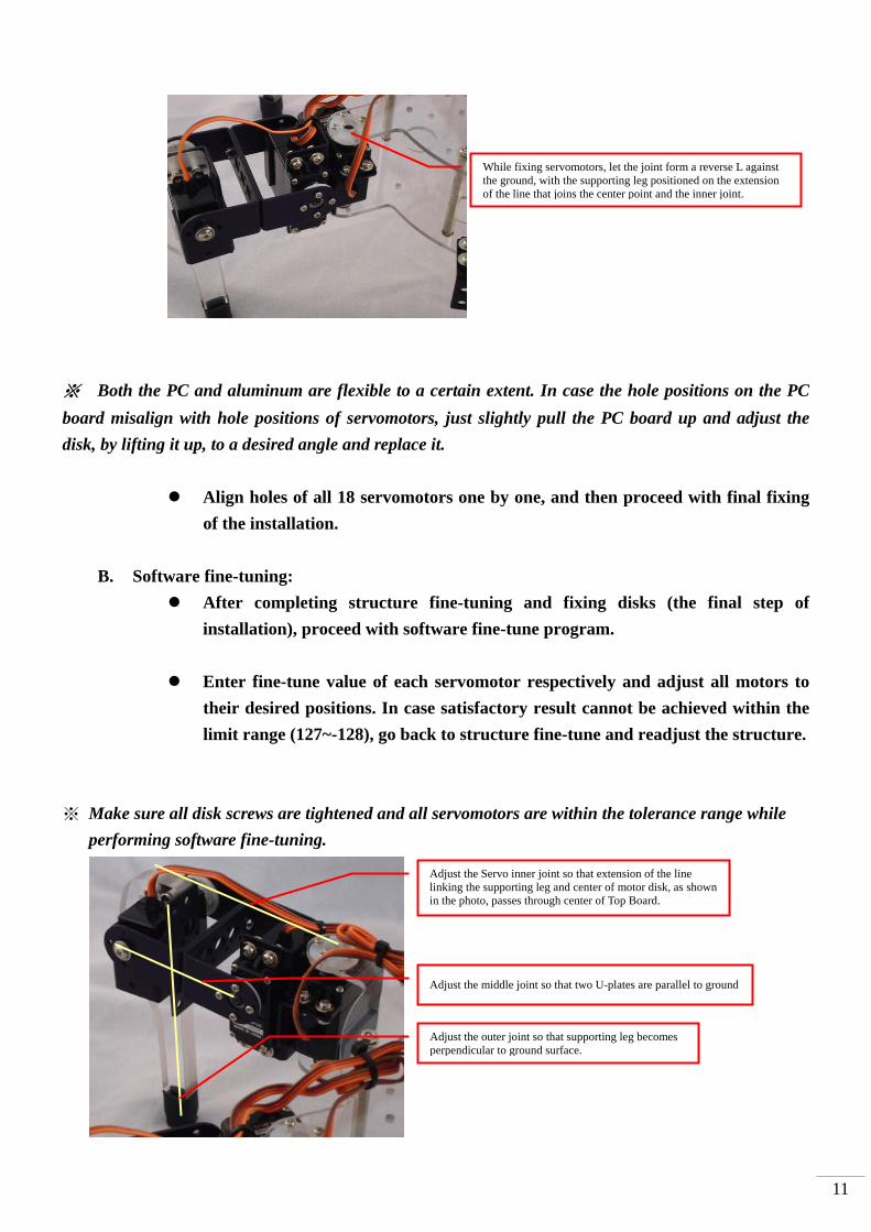
※ Both the PC and aluminum are flexible to a certain extent. In case the hole positions on the PC
board misalign with hole positions of servomotors, just slightly pull the PC board up and adjust the
disk, by lifting it up, to a desired angle and replace it.
Align holes of all 18 servomotors one by one, and then proceed with final fixing
of the installation.
B. Software fine-tuning:
After completing structure fine-tuning and fixing disks (the final step of
installation), proceed with software fine-tune program.
Enter fine-tune value of each servomotor respectively and adjust all motors to
their desired positions. In case satisfactory result cannot be achieved within the
limit range (127~-128), go back to structure fine-tune and readjust the structure.
※ Make sure all disk screws are tightened and all servomotors are within the tolerance range while
performing software fine-tuning.
Adjust the Servo inner joint so that extension of the line linking the supporting leg and center of motor disk, as shown in the photo, passes through center of Top Board.
Adjust the middle joint so that two U-plates are parallel to ground
Adjust the outer joint so that supporting leg becomes perpendicular to ground surface.
While fixing servomotors, let the joint form a reverse L against the ground, with the supporting leg positioned on the extension of the line that joins the center point and the inner joint.

12
B_1. Connect the PC and the BASIC Commander® on the 6-Legged Robot with the
USB line.
B_2. Make sure the power switch on the Command Board is at the 0 position. If not,
please slide it to the 0 position.
B_3. Connect the power line of the servomotor to the power supply (Please make sure
that the voltage and current from the power supply are within the range
required by the servomotor. After connecting the power line, the servomotor will
make a transient motion due to receiving the switch surge, which is normal.
While connecting the power cord, please pay attention not to place your hands
within the space where the servomotor will move into to avoid being clamped.)
B_4. Start InnoBASIC™ Workshop.
B_5. Click “Tools” in the menu bar on the top.
Click the application under the InnoBASIC™ Workshop folder to start the InnoBASIC™ Workshop
The connectors at the two ends of the USB line are of different sizes, so please connect the smaller one to the BASIC Commander®.
While connecting the power cord, please notice the polarity. Connect the two red wires together.

13
B_6. Click the “Motion Editor” in the pull-down menu (If a warning window appears,
it means that the BASIC Commander® is not correctly connected. Please check if
the USB line is connected or unplug and then plug it again to ensure a correct
connection. Exit the Motion Editor and then re-click this button.)
B_7. If the connection is correct, the message “Download servo manager” will be
displayed on the PC screen meaning that the program is being downloaded.
Please slide the power switch on the Command Board to the 1 position and wait
a moment.
After clicking each item, a pull-down menu with more function items will be displayed. Please click the “Tools" item now.
Click “Motion Editor” to start the Motion Editor.
If this message appears, it means that the USB line is not connected correctly.
The message means that the program is being downloaded. Please do not remove the USB line.

14
B_8. After the downloading is complete, a notification window will appear. Please
make sure that each servomotor has been connected correctly. After confirming
all the connections, please click “OK”. (If “Cancel” is clicked, the Motion Editor
will be closed. If there is any component is incorrectly connected at this moment,
please click “Cancel” to terminate the program.)
B_9. Please pay attention not to place your hands within the space where the
servomotors may move into to avoid being clamped. Please check the checkbox
for activating the servomotors on the left side to move all the servomotors to
their central points. Please note that the number next to it should be 1500. If it is
not 1500, please click the number directly, enter the number 1500 and then click
“Enter”.
B_10. Click the “Adjust Offset” button at the upper right corner.
B_11. If the fine tune values are not yet stored, the Filename will be “Untitled”. The
user can specify a preferred name while storing the file.
The message appears for notifying the download is complete. Please make sure that the servomotors have been connected correctly at the specified positions.

15
B_12. Observe the servomotor that requires the fine tune and click the corresponding
arrow buttons. The servomotor will rotate in the selected direction. Please make
sure that the rotation is in the correct direction. If the reverse rotation is
required, click the opposite arrow button. Adjust each servomotor to its central
point one by one.
B_13. Please note the values after fine tune. Click “Save”, select the location for storing
the file, enter a preferred filename, and then click OK to save the values in the
PC. If it is required to query or download the values, click “Load” to read out
the values.
The left/right arrow buttons can be used to rotate the servomotor clockwise or counterclockwise. Please observe the rotation of the servomotor to the required central position. Then adjust the next servomotor.
Please enter a preferred name in the “File name” and then click “Save”.
After the file is successfully stored, the filename of the last stored file will be displayed in the “Filename”.

B_14. Click the “Close” button at the lower right corner to close the window.
Click the “Close” button to close the window.
16

1
B_15. After returning the “Edit Servomotor Motion” window, click the “Exit” button
at the lower right corner to close the fine tune operation.
Click the “Exit” button to close the Motion Editor.
2
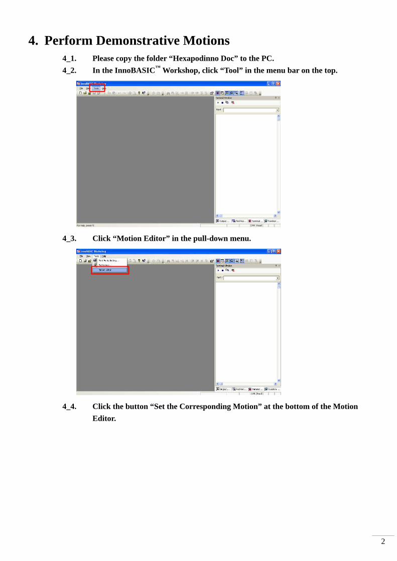
4. Perform Demonstrative Motions 4_1. Please copy the folder “Hexapodinno Doc” to the PC.
4_2. In the InnoBASIC™ Workshop, click “Tool” in the menu bar on the top.
4_3. Click “Motion Editor” in the pull-down menu.
4_4. Click the button “Set the Corresponding Motion” at the bottom of the Motion
Editor.
3
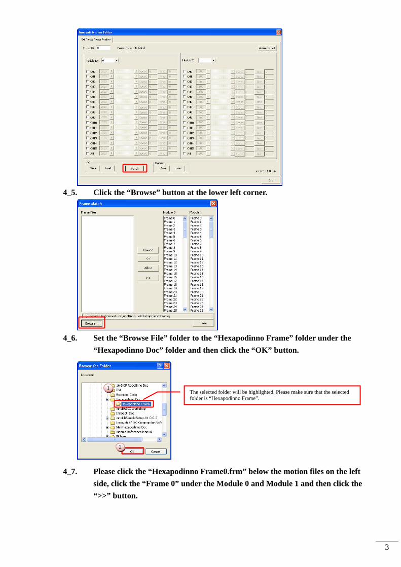
4_5. Click the “Browse” button at the lower left corner.
4_6. Set the “Browse File” folder to the “Hexapodinno Frame” folder under the
“Hexapodinno Doc” folder and then click the “OK” button.
4_7. Please click the “Hexapodinno Frame0.frm” below the motion files on the left
side, click the “Frame 0” under the Module 0 and Module 1 and then click the
“>>” button.
The selected folder will be highlighted. Please make sure that the selected folder is “Hexapodinno Frame”.
1
2
4
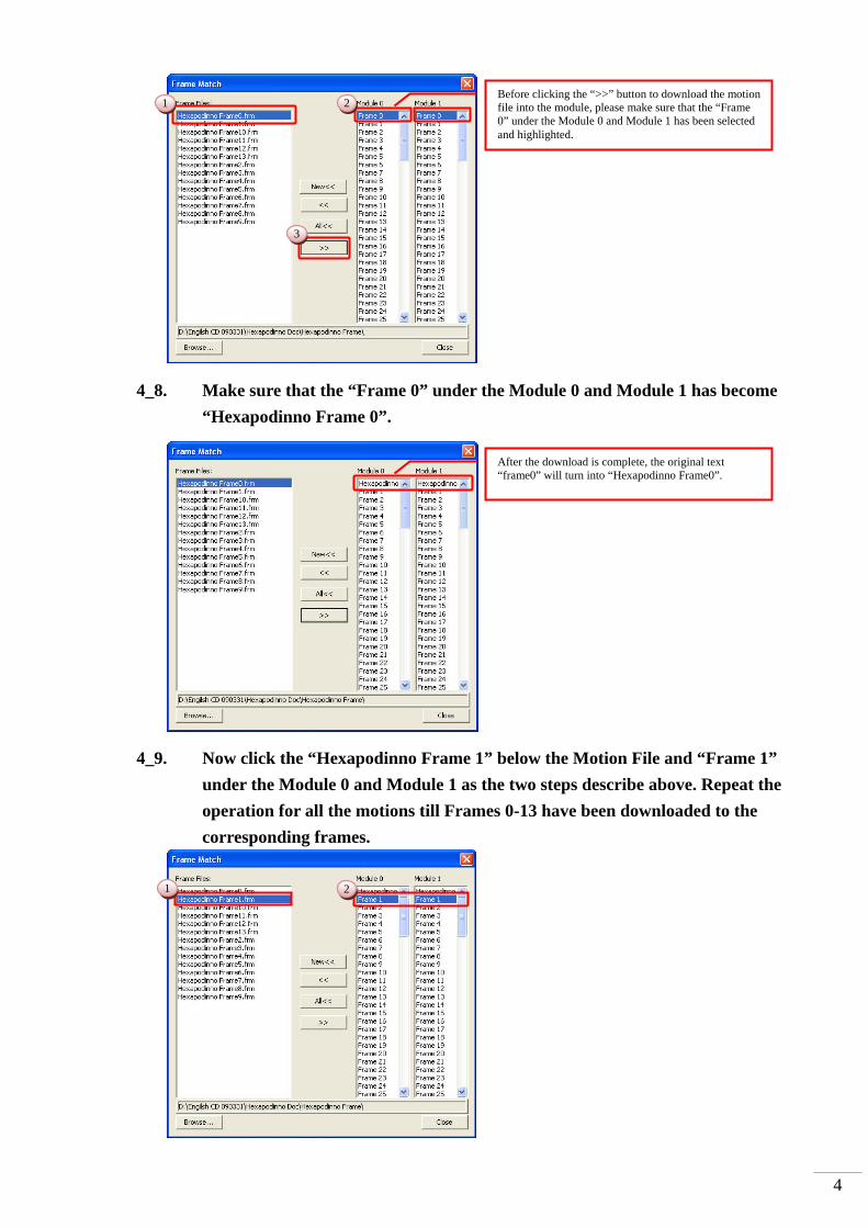
4_8. Make sure that the “Frame 0” under the Module 0 and Module 1 has become
“Hexapodinno Frame 0”.
4_9. Now click the “Hexapodinno Frame 1” below the Motion File and “Frame 1”
under the Module 0 and Module 1 as the two steps describe above. Repeat the
operation for all the motions till Frames 0-13 have been downloaded to the
corresponding frames.
Before clicking the “>>” button to download the motion file into the module, please make sure that the “Frame 0” under the Module 0 and Module 1 has been selected and highlighted.
After the download is complete, the original text “frame0” will turn into “Hexapodinno Frame0”.
1 2
3
2 1

5
4_10. After all the download operations are complete, it is clear that all the motions
above Frame14 under the Module 0 and Module 1 have been changed to the
corresponding motions.
4_11. After the verifying the operations, click the “Close” button at the lower right
corner to close the window for setting the corresponding motions.
4_12. In the Edit Servomotor Motions window, click the “Exit” button at the lower
right corner to close the Motion Editor.
Please make sure that first 14 Frames have been successfully downloaded.
6
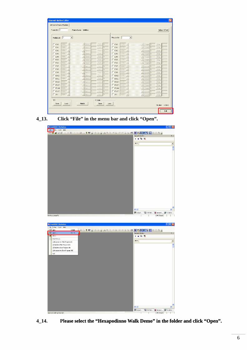
4_13. Click “File” in the menu bar and click “Open”.
4_14. Please select the “Hexapodinno Walk Demo” in the folder and click “Open”. ease select the “Hexapodinno Walk Demo” in the folder and click “Open”.

7
4_15. Move to the 118st line of the program to see the Initial Function. (To move within
the program, the user can also click the mouse button at any position in the
program and then rotate the mouse wheel to scroll the program page.)
4_16. Update the fine tune values, which are recorded during the software fine tune,
into the Initial Function to replace the original values of “0”.
4_17. Slide the power switch from the 1 position to the 0 position to prevent the
6-Legged Robot from starting the motion directly after the program is
successfully created.
The selected folder will be highlighted. Please make sure that the selected folder is “Hexapodinno Walk Demo”.
Click the “Open” button to download the program into the innoBASIC Workshop for editing or creating motions.
The number on the left side represents the line number of the program. The Function starts at “Sub” and ends at “End Sub” within which the operations are defined to store the fine tune values into the module. At the beginning of each program, it is necessary to set the fine tune values.
The SetPosOffset command has two parameters: one is the Servomotor ID and the other is the fine tune value. Please enter the fine tune value according to the value recorded for each servomotor ID. The number in the figure is arbitrarily defined, Please do not enter the same number as shown in the figure.
1
2

8
4_18. Press the “Build” button and wait until the download is complete.
4_19. Remove the USB line that has been connected to the 6-Legged Robot and place
the 6-Legged Robot at a location prepared for performing the motion operations.
4_20. Slide the power switch from the 0 position to the 1 position. The 6-Legged Robot
will perform a forward movement according to the demonstrative program.
If the user is not sure about the function of each button, the user can move the mouse pointer over the image. After a while, the English name will automatically appear. After click the "Build" button, the program will be downloaded into the BASIC Commander and stored automatically. According to the layout, the "Build" button may appear at different position.
After the download is complete, the output window will display the used memory space. If there is any error, it will be displayed in the output window. Please make sure that no error is displayed in the output window.
Top Related