


Languages
Pages
Legal


HARBINROPVINDUSTRYDEVELOPMENTCENTER
8InchEndPortFRPPressureVessel
UserManual
Models:
R8040B300E/R8040B450E
HeadquartersTel:(+86)451‐82267301Fax:(+86)451‐82267303Email:[email protected]:www.ropv.com.cn
GlobalMarketPhone:(+1)925‐237‐0184Fax:(+1)925‐264‐1951Email:[email protected]:en.ropv.com.cn/en

8InchEndPortFRPPressureVesselUserManual
- 1 -
TableofContents
CHAPTER 1 GENERAL PRODUCT DESCRIPTION ....................................................................................... ‐ 3 ‐
Product Identification .................................................................................................................................... ‐ 3 ‐
Operation Specifications ............................................................................................................................... ‐ 4 ‐
Vessel Use and Precautions ........................................................................................................................... ‐ 4 ‐
CHAPTER 2 INSTALLATION ..................................................................................................................... ‐ 6 ‐
CHAPTER 3 PIPING CONNECTIONS ......................................................................................................... ‐ 7 ‐
3.1. Permeate Port Connections................................................................................................................. ‐ 7 ‐
3.2. Feed/Concentrate Port Connections ................................................................................................... ‐ 7 ‐
CHAPTER 4 MAINTENANCE GUIDE ......................................................................................................... ‐ 9 ‐
4.1. Preventive Maintenance ..................................................................................................................... ‐ 9 ‐
4.2. Opening the Vessel .............................................................................................................................. ‐ 9 ‐
4.3. Head Disassembling. .......................................................................................................................... ‐ 11 ‐
4.4. Head Assembly Cleaning and Inspection. .......................................................................................... ‐ 13 ‐
4.5. Head Assembly. ................................................................................................................................. ‐ 14 ‐
CHAPTER 5 LOADING/REPLACING MEMBRANE ELEMENTS .................................................................. ‐ 18 ‐
5.1. Inspection .......................................................................................................................................... ‐ 18 ‐
5.2. Disassemble membrane components ............................................................................................... ‐ 18 ‐
5.3. Unload the membrane ...................................................................................................................... ‐ 18 ‐
5.4. Check and make sure the head is assembled according to Head Disassembly and Head Assembly. ‐ 18 ‐
5.5. Vessel cleaning and inspection .......................................................................................................... ‐ 19 ‐
5.6. Install the head at the concentration side ......................................................................................... ‐ 19 ‐
5.7. Install locking kit segment at concentration side. ............................................................................. ‐ 20 ‐
5.8. Load membrane elements from the feed end of the vessel ............................................................. ‐ 20 ‐
CHAPTER 6 CLOSING THE VESSEL ......................................................................................................... ‐ 22 ‐
CHAPTER 7 HANDLING AND STORAGE ................................................................................................. ‐ 24 ‐
7.1. Vessel Handling Precautions .............................................................................................................. ‐ 24 ‐

8InchEndPortFRPPressureVesselUserManual
- 2 -
7.2. Storage Requirements ....................................................................................................................... ‐ 24 ‐
CHAPTER 8 BREAKDOWNS AND SOLUTIONS ........................................................................................ ‐ 26 ‐
8.1. Locking Kit Segment and Related Issues. ........................................................................................... ‐ 26 ‐
8.2. Head and Related Issues. ................................................................................................................... ‐ 26 ‐
8.3. Vessel and Related Issues. ................................................................................................................. ‐ 27 ‐
8.4. Feed/Concentrate Side Ports and Related Issues. ............................................................................. ‐ 28 ‐
8.5. Low Permeate Water Quality ............................................................................................................ ‐ 28 ‐
CHAPTER 9 SERVICE GUIDE .................................................................................................................. ‐ 30 ‐
Appendix I .................................................................................................................................................... ‐ 31 ‐
Pre‐ Running Check List ............................................................................................................................... ‐ 31 ‐
Appendix II ................................................................................................................................................... ‐ 32 ‐
Maintenance Check List ............................................................................................................................... ‐ 32 ‐
ROPV Limited Warranty ............................................................................................................................... ‐ 33 ‐

8InchEndPortFRPPressureVesselUserManual
- 3 -
Chapter1 GeneralProductDescription
ROPV pressure vessel is designed to withstand 6 times the designed pressure before acatastrophic failureoccurs.Asasafetyprecaution thehousingsaredesigned fora fullbodyleak at 4 times the design pressure to keep catastrophic failure from happening. Eachstandardvessel iscarefully inspectedandahydro‐test isperformed toensure its reliabilitybeforedeliveringfromtheplant.ROPV Pressure Vessels are designed to provide safe operation over a long service life ifproperlyinstalled,operated,andmaintained.Thevesselmaycauselossoflife,severebodilyharm, or property damage if improperly installed, operated, or maintained. Read andunderstand all guidelines provided in the vessel User Manual. Observe every precautioncontained therein. Failure to do so may result in malfunction and potential catastrophicfailure. It isrecommendedthatonlyqualifiedtechniciansexperiencedinservicinghydraulicsystems work with this vessel. Misuse, incorrect assembly, or use of damaged/corrodedcomponents may result in catastrophic failure. ROPV Pressure Vessels are design andmanufactureinaccordancewiththeAmericanSocietyofMechanicalEngineers,ASME,SectionXBoilerandPressurevesselsCoderequirements,foruseasamembraneelementhousing.
ProductIdentification
ROPV
R 8040 B 300 S ‐ 6 (W)
8InchDiameterMembrane
MembraneLength40Inch
BSeries
MembranesperVessel
PaintColorWhite
Feed/ConcentrateSidePortConnection
MaximumOperatingPressure(PSI)
R 8040 B 300 E ‐ 6 (B)
PaintColorBlue
Feed/ConcentrateEndPortConnection
8InchEndPortFRPPressureVesselUserManual
- 4 -
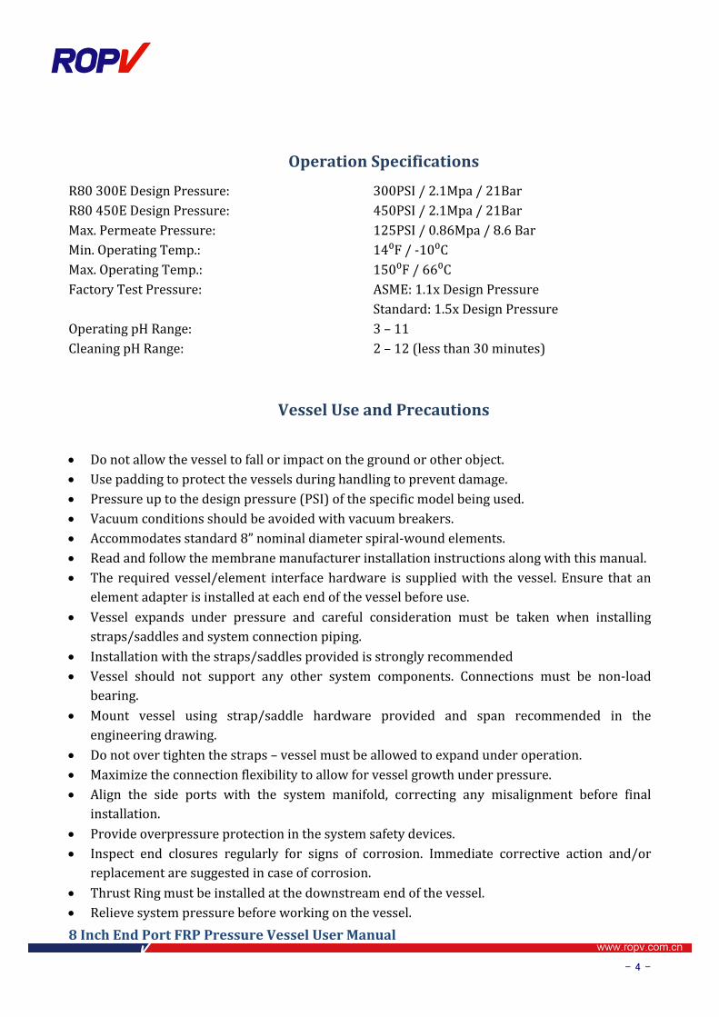
OperationSpecifications
R80300EDesignPressure: 300PSI/2.1Mpa/21BarR80450EDesignPressure: 450PSI/2.1Mpa/21BarMax.PermeatePressure: 125PSI/0.86Mpa/8.6BarMin.OperatingTemp.: 14⁰F/‐10⁰CMax.OperatingTemp.: 150⁰F/66⁰CFactoryTestPressure: ASME:1.1xDesignPressure
Standard:1.5xDesignPressureOperatingpHRange: 3–11CleaningpHRange: 2–12(lessthan30minutes)
VesselUseandPrecautions
Donotallowthevesseltofallorimpactonthegroundorotherobject. Usepaddingtoprotectthevesselsduringhandlingtopreventdamage. Pressureuptothedesignpressure(PSI)ofthespecificmodelbeingused. Vacuumconditionsshouldbeavoidedwithvacuumbreakers. Accommodatesstandard8”nominaldiameterspiral‐woundelements. Readandfollowthemembranemanufacturerinstallationinstructionsalongwiththismanual. The requiredvessel/element interfacehardware is suppliedwith thevessel.Ensure thatan
elementadapterisinstalledateachendofthevesselbeforeuse. Vessel expands under pressure and careful consideration must be taken when installing
straps/saddlesandsystemconnectionpiping. Installationwiththestraps/saddlesprovidedisstronglyrecommended Vessel should not support any other system components. Connections must be non‐load
bearing. Mount vessel using strap/saddle hardware provided and span recommended in the
engineeringdrawing. Donotovertightenthestraps–vesselmustbeallowedtoexpandunderoperation. Maximizetheconnectionflexibilitytoallowforvesselgrowthunderpressure. Align the side ports with the system manifold, correcting any misalignment before final
installation. Provideoverpressureprotectioninthesystemsafetydevices. Inspect end closures regularly for signs of corrosion. Immediate corrective action and/or
replacementaresuggestedincaseofcorrosion. ThrustRingmustbeinstalledatthedownstreamendofthevessel. Relievesystempressurebeforeworkingonthevessel.

8InchEndPortFRPPressureVesselUserManual
- 5 -
Donot attempt to over‐tighten thePermeatePort connections as thismaydamage the endclosure.Oneturnpasthandtightshouldbesufficient.
Neveroperatethevesselinexcessofitsratings.Thismayvoidthewarrantyandcausebodilyorpropertydamage.
Donotoperatethevesselpermeateportover125PSI. Flushthevesselwithpermeatebeforesystemshutdowntoreducethechanceofcorrosion. Donotinstallthevesselunderdirectsunlight. OperatethevesselwithintherecommendedpHrange‐OperatingpHRange:3–10,Cleaning
pHRange:2–12(lessthan30minutes). Minimizemembranemovementbycarefulshimmingthemembranecolumn. Failuretounderstandandfollowallprecautionsmayvoidwarrantyandresultincatastrophic
failureofthevessel. These guidelines are subject to change. Please check with ROPV to ensure that the User
Manualisthelatestversionforthevesselmodelbeingused.

8InchEndPortFRPPressureVesselUserManual
- 6 -
Chapter2 Installation2.1. Carefully study the vessel engineering drawings for key dimensions and technical
requirements.2.2. Designandmanufacturerackaccordingtoengineeringdrawingsandsystemcapacity.
Independentsupportofbothpressurevesselandmanifoldsshallbeconsideredinthedesignoftherack.
2.3. Check the integrity of the vessel, especially the inner surface of the vessel and thesealingsurfaceoftheFeed/Concentrateports.
2.4. Ensureenoughspaceisreservedaroundthetwoendsofthevesselforinstallationandremovalofthemembraneelements.
NOTE: InstallthevesselscenteredontheracktoavoidstressconcentrationontheFeed/Concentrateports.2.5. Mountthevesselontheprovidedsaddlesattherecommendedspanpositionsshown
ontheengineeringdrawings.2.6. Connect the vessel to themanifolds and/or to the next vesselwhile adjusting each
vesselandmanifoldtominimizemisalignmentateachend.(Fordetails,see“Chapter4PipingConnections”).
2.7. Installthestrapassembly.Installthescrewsthroughtheholeintherackandthreadthemintothestraplocknut;useatorquewrenchtotightenthescrewswithin3~5N.m.NOTE:Pressurevesselsexpandduringpressurization,overtighteningthestrapassemblieswilldamagethevessel.
2.8. Assembleendclosure(Fordetails,see“HeadAssembly”in“MaintenanceGuide”)2.9. Install membrane elements(For details, see “Membrane Elements Installation” in
“MaintenanceGuide”)2.10. Installthrustringatthedownstreamendofthevessel.2.11. Closethevessel.2.12. Connectthepermeateportmanifolds(Fordetails,see“PipingConnections”)2.13. Inspect the installation. Inspection includesbut isnot limited tothepositionof the
vessel, the end caps and pipelines connections. Please inspect according to “Pre‐PressurizingCheckinglist”inAppendix1.
2.14. Pressurizeandrunthesystem.Ifindoubtorforinstallationissues,pleasecontactROPV.

8InchEndPortFRPPressureVesselUserManual
- 7 -
Chapter3 PipingConnectionsEnoughroomshallbereservedforbothaxialandradialexpansionof thevessel inthedesignofthe
manifoldsandpipelines;otherwisethevesselandothercomponentsofthesystemcouldbedamaged.
There are some location deviation about feed\concentrate ports and permeate ports connecting,
considerthesedeviationwhendesignthepipingconnection,otherwisethestressconcentrationmay
damagethepipe.Carefulreadingofthischapterwillfacilitatesafeandnormalworkingconditionsof
thevesselandpipelines.
3.1. PermeatePortConnections
3.1.1. Useflexibleconnectionstoreducevibrationimpact.
3.1.2. AUswan‐necktubingwithflexibleconnectorsatbothends,oronepieceofflexiblesoftpipe
shouldbeusedforpermeateportconnections.
3.1.3. Extraand independentsupportshallbeprovided forpermeateportpipelinesrather than
usingpermeateportassupport.
Note:Topreventdamage to thepermeateportdonot tighten thepermeateport conections
over50N.moftorque.
3.2. Feed/ConcentratePortConnections
3.2.1. Useflexiblegroovedcouplings(IPS).3.2.2. Donotconnectanymanifoldsrigidlytothevessel.
3.2.3. Manifoldsmustbesupportedindependently.
3.2.4. Manifold span should be greater than vessel span to allow for vessel growth under
pressure.
3.2.5. Toreducetheriskofstressconcentrationwerecommendthat“twoIPSstandardflexible
couplings and one piping section” are used to connect the Feed/Concentrate ports and
manifoldports; thismethodlowersrequirements forhousingalignmentandtheposition
accuracy of the manifold welds. However, this method will increase the initial cost as
showninfigure1.1.
Figure1.1
90⁰BendConnection
Manifold
IPSGrooved
PressureVessel PressureVessel
IPSGroovedManifold
StraightConnection

8InchEndPortFRPPressureVesselUserManual
- 8 -
MaximumMisalignment.76mm
Figure1.3
3.2.6. The use of only one IPS standard coupling to connect directly to the manifolds is also
acceptable. However, the welding of the manifolds and the installation position of the
housing should be accurately controlled to ensure the proper alignment of themanifold
andtheFeed/Concentrateports.
3.2.7. Install the vessel correctly: Make sure to align the Feed/Concentrate ports and the
manifoldportsataright distance.Please contact the supplier of coupling to get the exact distance.
3.2.8. Connecting the vessel and themanifold: Since only one IPS coupl i n g i s u s e d t o connect directly to themanifold precautions shall be taken to ensure additional flexiblespace is provided for the connection of vessels and manifolds by adding an extra IPS
couplingtothe
manifold,asshowninfigure1.2.
3.2.9. SlightanglebetweenmanifoldsandF/CportsusingIPSstandardclampforconnectionis
acceptable.However,highaccuracyinalignmentisrequired.Misalignmentinanydirection
should be avoided and keep to a minimum as much possible since it will generate
mechanicalstressconcentrationsthatwilldamagethemembranehousing.
3.2.10. Verify the alignment: There is a maximum of 0.76mm misalignment tolerance in any
direction forallportsas shown in figure1.3. Severemisalignment could impair the life
expectancy of the vessel. Excessive force to tighten the couplings is an indication of
misalignment.Whenproperlyalignedcouplings shouldbeable to turn slightlybyhandafterinstallation.
Figure1.2
DistributionManifoldPressureVessel
SingleIPSGrooved
ManifolIntermediateIPSGroovedCoupling IPSGroovedCoupling

8InchEndPortFRPPressureVesselUserManual
- 9 -
Chapter4 MaintenanceGuide4.1. PreventiveMaintenance
Periodical cleaning and maintenance of the vessel and replacement of damaged components is
essentialtoensureasafeandnormaloperationofthevesseloveralongservicelife.
AsarecommendationwesuggesttofollowthePreventionChecklistbelow:
Endclosures.
Periodicallycleanandremoveanysaltand/orcorrosiondeposits.
Inspectcomponentsfordeteriorationandreplaceasneeded.
Maintainexternalcomponentsdryandleakfree.SidePorts.
Inspectforleakage.
Inspectcouplingconnectionsforcorrosionandreplacedeterioratedcouplingsasneeded.
Maintainallsideportsdryandleakfreetopreventcorrosion.
4.2. OpeningtheVessel
4.2.1. ShutDownSystemandRelieveSystemPressure–Thesystemmustbeshutdownandall
pressurerelievedbeforeconductinganymaintenanceorrepaironthevessel.Readand
followallrelatedguidesprovidedbysystemprovider.
4.2.2. Disconnectpermeateportpiping.Unscrewandremovethepermeateportpipingusinga
wrench.Payattentiontothethread‐turningdirectiontopreventanydamagetothe
permeateportduetoreversedturningorover‐turning.
4.2.3. InspectEndClosure–Theendclosureshouldbeinspectedforanysignsofcorrosionor
damage.Surfacecorrosionandsaltdepositscanberemovedwithabrushorscrubbing
pad,whileflushingwithwater.Damagedcomponentsshouldbereplacedwithapproved
componentsfromROPV.
4.2.4. Removethelockingkitsegmentscrewsusingahexwrench.
Readthissectioncompletelybeforeservicingthevessel.DONOTServiceanycomponentuntilyouverifythat
systempressureisfullyrelievedfromthevesselandthesystemiscompletelyshutdown.
WARNING

8InchEndPortFRPPressureVesselUserManual
- 10 -
4.2.5. Liftthelockingkitsegmentoutoftheretaininggrooveusingascrewdriver.Shouldthe
assembliesbedifficulttoremove,itmaybenecessarytorocktheheadslightlyortapthe
headinwardwitharubbermallet.Removetheendclosure.Itisrecommendedtouse
dedicatedendclosureremovaltoolsfromROPV.
4.2.6. RemovetheHeadAssemblywithOneoftheFollowingTechniques
4.2.6.1. ROPVHeadRemovalTool–AheadremovaltoolsetisavailablefromROPV.
Whilenotnecessaryforheadremoval,theyhaveprovenaneffectiveandeasyway
toremovethevesselheadwithoutcausinganydamagetothevessel.Therearefour
components:bearingblock,positionnut,bearingrod,centerpiece.
4.2.6.1.1. Threadthecenterpieceintothepermeateportoftheheadassembly,to
handtight.Donotovertightenthecenterpiece(Fig.2.3).4.2.6.1.2. Placethebearingblockattheendface.
4.2.6.1.3. Threadthepositionnutintothecenterpiece.
Figure2.2ROPVHeadRemovalTool
Figure2.1.

8InchEndPortFRPPressureVesselUserManual
- 11 -
4.2.6.1.4. Turnbearingrodclockwise.Theheadwillmovewiththebearingrodas
itmovestowardtheendofthevessel.Youwillbeabletoremovethehead
onceithasclearedtheretaininggrooveareaofthevessel.
4.2.6.2. AlternativeHeadRemoval–Itispossibletoremovetheheadassembly
withouttheROPVheadremovaltools.A1”NPTMalethreadedpieceofPVC(or
similarmaterial)pipeshouldbethreadedintotheheadpermeateporttohand
tightness.Pullthepipeoutwardtoremovethehead.Ifthevesselhasbeenin
operationforanextendedtime,aslightrockingmotionorforcefultugmaybe
requiredtobreaktheheadsealbond.Also,ahandleattheendofthepipewillease
headremoval–formingaTwiththepipethatthreadsintothepermeateport.
4.3. HeadDisassembling.
Readthisarticlecarefullybeforedisassemblingtheheadassemblytoprevent
damagingitscomponents.
4.3.1. Inspection:Makesurethattheendcapisremovedfromthevesselaccordingto
<OpeningtheVessel>
Figure2.5. Figure2.6.
Figure2.3. Figure2.4.

8InchEndPortFRPPressureVesselUserManual
- 12 -
4.3.2. Removetheadaptorandseals:Holdthebearingplatetightlywithonehandandpull
theadaptoroutofthepermeateportwiththeotherhand;removetheadaptorsealsand
thesealingplateseals.
4.3.3. Removethepermeateportlocknut:Removethelocknutusingadedicatedwrench.The
locknutislefthandthreadedandmustbeturnedclockwisetoberemoved.
4.3.4. Separatethebearingplateandsealingplate.Pullthesealingplatewithonehandto
separateitfromthebearingplate.
4.3.5. Separatedthepermeateport,andremovethefeed\concentrateport:pullthe
permeateportandfeed/concentrateportoutofthesealingplateandremovethe
retainingringofthefeed/concentrateport.
4.3.6. Removethesealsfromthesealingplateandpermport.
Figure2.9
Figure2.10
Figure2.7Removethelocknut Figure2.8Removesealingplate

8InchEndPortFRPPressureVesselUserManual
- 13 -
4.4. HeadAssemblyCleaningandInspection.Pleasereadthissectioncarefullybeforemakingdecisionsandtakingmeasureson
componentstructureorcorrosionproblems.Pleasecombinetheoperational
experiencewiththismanualtodealwithcorrosionandcomponentdamage.Youcan
referto<Breakdownsandsolutions>forthecontentthatisnotincludedinthissection
orcontactROPVforconditionsnotcoveredinthismanual.
4.4.1. CleaningandInspectionofthemetalliccomponents.
Metalliccomponentsincludethealuminumbearingplate,stainlesssteellockingkit
segmentsandscrews.
4.4.2. Inspectthecomponentsforscale,saltdepositorcorrosion;useasteelbrushora
scrubbingpadtoloosenanydeposit.Becarefulnottoscratchthebearingplate
anodizecoating.
4.4.3. Placethecomponentsintoavesselfilledwithmildsoapsolutionandremovethe
corrosion.
Carefully remove the seals to prevent damage to the sealing surfaces. It is recommended to replace all used
seals with brand new seals. NOTE
Figure2.11Headbreakdown
Components:sealingplate,adaptor,bearingplate,feed/concentrateport,retainingrings,
permeateportplug,permeateportlocknut,seals.

8InchEndPortFRPPressureVesselUserManual
- 14 -
4.4.4. Flushallcomponentswithcleanwater.
4.4.5. Drythecomponentswithcompressedairoracleananddrytowel.
4.4.6. Inspectallcomponentscarefully,checkforanystructuraldefectsordamageinthe
bearingplateanodizedcoating.Replaceanydamagedordefectivecomponent.
4.4.7. CleaningandInspectionofthenon‐metalliccomponents.Non‐metallic
componentsincludesealingplate,permeateport,adaptor,permeateportlocknut,
permeateportplugandallseals.
4.4.8. Inspectcomponentsforscale,corrosionorsaltdeposit.Placethecomponentsintoa
bucketfilledwithmildsoapsolutionandcleanthemtoremovethedeposits.
4.4.9. Flushallcomponentswithcleanwater.
4.4.10. Drythecomponentswithcompressedairoracleananddrytowel.
4.4.11. Inspectallcomponentscarefullyforanystructuraldefectsordamageintheseals.For
example,cracksinthepermeateportorthelocknut,damageinthethreads;aged,
deformedordamagedseals.Replaceanydamagedordefectivecomponentwithnew
ones.
4.4.12. Replaceallcomponentsthatneedtobechangeduponinspection.
4.4.13. InspectcarefullytheFeed/Concentrateportsandattachmentstotheshelltoensure
thatconnectionsandsealsarestructurallysound.PleasecontactROPVforany
questions.Pleasedonotconductanyrepairworkbeforeconsultingwiththe
manufacturerforguidance,exceptforreplacingheadcomponents.
4.5. HeadAssembly.
Readandfollowthissection.Incorrectassemblymayresultincatastrophicheadfailure.
If chemical reaction problems occur like cracks or discoloration on the vessel or its components, please contact please contact ROPV at: [email protected]
NOTE
We recommend using brand new seals for head assembly.
Lubricate seals using glycerin or silicone base lubricant.
ATTENTION

8InchEndPortFRPPressureVesselUserManual
- 15 -
4.5.1. Lubricateandinstalltheseals:
Lubricatethepermeateportsealsandplacetheminthegrooveslocatedontheinside
diameterofthepermeateport.Lubricatethepermeateportsealsandplaceitontothe
outeredgeofthepermeateport.
4.5.2. Lubricatethesealingplatesealsandplaceitinthegrooveslocatedontheinsidediameter
ofthesealingplate.
4.5.3. Lubricatetheadaptorsealsandplacetheminthegroovesoftheadaptor.
Figure2.13Installthepermeateportseals
Figure2.14Installthesealingplateseals
Figure2.15Adaptorsealsinstallation

8InchEndPortFRPPressureVesselUserManual
- 16 -
4.5.4. Assemblethesealingplateandbearingplate:
Applyathinlayeroflubricantontothesealingsurfaceofthefeed/concentrateportand
pushthefeed/concentrateportthroughtheholeofthesealingplate,thenfixitwith
retainingring.
4.5.5. Insertthelongerendofthefeed/concentrateportthroughtheholeofthebearingplate
untilfullcontactofthesealingplateandbearingplate.Thenapplyathinlayerof
lubricantontothesealsurfaceofthepermeateport,pushthepermeateportthroughthe
holeofthepartedsealingplatetothebottom.
4.5.6. Threadthepermeateportlocknutontothethreadsofthepermeateportusingawrench
untilthesealingplateandbearingplatearethoroughlycontacted.
Figure2.16Installingfeed/concentrateport
Figure2.16Assemblingsealplate Figure2.17Assemblingbearingplate
Figure2.18Installinglocknut 2.19Installingadaptor
8InchEndPortFRPPressureVesselUserManual
- 17 -
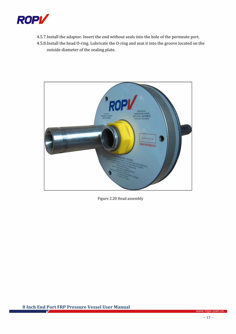
4.5.7. Installtheadaptor.Inserttheendwithoutsealsintotheholeofthepermeateport.
4.5.8. InstalltheheadO‐ring.LubricatetheO‐ringandseatitintothegroovelocatedonthe
outsidediameterofthesealingplate.
Figure2.20Headassembly
8InchEndPortFRPPressureVesselUserManual
- 18 -
Chapter5 Loading/ReplacingMembraneElementsReadallpartsofthissectionbeforereplacingmembraneelements.Thisarticleisforreference
only; load/unload the membrane elements according to the membrane manufacturer
requirements.
Membraneelementsmustbe loadedat the feed (upstream)endof thevessel,andunloaded
throughtheconcentrated(downstream)sideofthevessel.Alwaysremoveandinstallelements
inthedirectionoffeedflow.
Make amatching list for the removedmembrane and the vessel to avoid possible disorder
duringmembraneloading
Steps:
5.1. Inspection
5.1.1. Verifyallpressurehasbeenrelievedfromthevessel,followingsystemmanufacturer’s
recommendations.
5.1.2. EnsurethevesselisopenedaccordingtoOpeningtheVessel.
5.2. Disassemblemembranecomponents
5.2.1. Removethethrustringlocatedattheconcentrationside.
5.2.2. Removetheadapterfromthemembranesonbothsidesofthevessel.
5.3. Unloadthemembrane
5.3.1. Cleanoffanylubricantresidueorsaltbuildupfromtheinsidediameteratbothendsof
thevessel.
5.3.2. Remove the membrane out of the vessel according to the membrane manufacturer
requirements.
5.4. Checkandmakesure thehead isassembledaccording toHeadDisassemblyandHead
Assembly.
Be careful not to scratch the inner surface of the vessel while removing or installing the
membrane elements.
ATTENTION

8InchEndPortFRPPressureVesselUserManual
- 19 -
5.5. Vesselcleaningandinspection
5.5.1. Cleanthe innersurfaceandgrooveof thevesselbyremovingtheresidueorcorrosions
withamildsoapsolutionandthenflushwithcleanwater.
5.5.2. Checkifthereisanydamagetotheinnersurfaceofthevessel.Ifyes,Pleasechangethe
vessel.
5.6. Installtheheadattheconcentrationside
5.6.1. Applyathinlayerofglycerinwithin50mmfromthegrooveontheinnersurfaceofthe
vesselattheconcentrate(downstream)endofthevessel.
5.6.2. Apply a thin layer of glycerin on the surface of the head O‐ring for the concentrate
(downstream)endofthevessel.
5.6.3. Installthethrustringontotheheadfortheconcentrate(downstream)endofthevessel.
5.6.4. Graspthepermeateportandthelocknuttokeeptheheadandthevesselinthesameaxis
and push the head into the vessel until some resistance can be felt. Then continue
pushing the head slowly into the vessel until it reaches over the groove. Pleasedonot
push the head toomuch over the groove since the sealsmay be damaged if the head
needstobepulledback.Ifitisdifficulttopushtheheadwithhands,arubbermalletcan
beusedtohittheheaduntiltheheadreachesitsplace.
Figure2.22Installthethrustring
Figure2.21Inspectingthevessel

8InchEndPortFRPPressureVesselUserManual
- 20 -
5.7. Installlockingkitsegmentatconcentrationside.
5.7.1. Inspectthegrooveandensureitiscleanandfreeofresidues.Usecompressedairtodry
thegrooveifavailableoruseacleanragtodryit.
5.7.2. Applylubricantlikeglycerinontothelockingkitsegmentscrewstopreventsaltdeposits
tobuildup.Positionthe lockingkitsegments intothegroove. Install thescrews, tighten
screwsupto10Nmoftorque.
5.8. Loadmembraneelementsfromthefeedendofthevessel
5.8.1. Inspectandconfirmtherearenoscratchesontheinnersurfaceofthevessel.
5.8.2. Inspect and ensure there is nothing on the outer surface of the membrane that may
scratchtheinnersurfaceofthevessel.
5.8.3. Usingacleanragorcottonandamixtureofglycerinandcleanwaterata1:1ratioball
lubricatetheinnersurfaceofthevessel.
5.8.4. Usingacleanragorcottonandamixtureofglycerinandcleanwaterata1:1ratioball
lubricatethemembraneseal.
5.8.5. Load the membrane from the feed end of the vessel; ensure that the membrane is
properlyorientated.Iftherearemorethanonemembranetobeloadedintothevessel,do
notpush the firstmembrane into the vessel completelybut reserve around200mm to
facilitatetheconnectionofthenextmembrane.
5.8.6. Inspect andmake sure themembrane interconnector is clean and intact. Apply a thin
layerofglycerinontotheinterconnectorsealswithoutexcessiveamount;otherwisethe
membranemaygetcontaminated.Installtheinterconnectorintotheloadedmembrane.
5.8.7. Installandconnectthenextmembranewiththeloadedonewiththeinterconnector.
Figure2.23Installlockingkitsegment

8InchEndPortFRPPressureVesselUserManual
- 21 -
5.8.8. Loadallmembraneelements in the sameway. Pushall themembranes into the vessel
until the adaptor at the concentration end is inserted into the center hole of the first
membraneandthemembranefaceispushedagainstthethrustring.
Please ensure all membranes are in the same axis. No load on the connection pipe, otherwise the
pipe or the membrane may be damaged.
ATENTION
8InchEndPortFRPPressureVesselUserManual
- 22 -
Chapter6 ClosingtheVesselPleasereadthisarticlecarefully.Incorrectassemblymayresultincatastrophicfailure.
6.1. Pre‐ClosingInspection
6.1.1. InspecttheheadisassembledasperHeadDisassemblyandHeadAssembly
6.1.2. VerifythatthemembranesareloadedasperLoading/ReplacingMembraneElements
6.1.3. Ensuretheinnersurfaceofthevessel isfreeofcorrosionbuilduporresidueof foreign
materials.
6.1.4. Inspectandmakesuretherearenoscratchesordamageontheinnersurfaceofthevessel.
6.1.5. Inspectthevesselgrooveandmakesuretherearenoresiduesorsaltbuildupinit.
6.1.6. InspecttheFeed/Concentrateportconnectionsandvessel,makesurethesealsareintact,
structurally soundand freeofcorrosion. Ifyouhaveanyquestionsor findanyadverse
situationpleasecontactROPV.
6.1.7. Shimming themembranes.Due to variationon the length of themembranes and the
vesseltolerance,shimmingmightbenecessarytopreventmembranemovementduring
operation.
6.1.7.1. Remove the adaptor seals and the headO‐ring. Insert the straight end of the
adaptorintothepermeatehubfarenoughtobeheldbytheadaptorseal.Alignthe
adaptorwith themembrane andpush the head carefully into the vessel until the
grooveisexposedfarenoughtoinsertalockingsegmentintoit.Slowlyremovethe
head with care and then check the size of the gap between permeate port and
adaptor.Thenumberof2mmshimsneededtofillthisgapwilldependonthesizeof
thegap.Reinstalltheadaptorsealsandsealplateseal;slideshimsontheflatendof
the adaptor and insert the adaptor into the permeate port hub. Shims must be
placedbetweenthepermeateportandadaptor.
6.2. Installheadatthefeedend(upstream)
6.2.1. Applyathinlayerofglycerinwithin50mmfromthegrooveontheinnersurfaceofthe
vessel.
6.2.2. ApplyathinlayerofglycerinontotheheadO‐ringatfeedend.
Please read this article before closing the vessel. DO NOT use corroded or damaged parts to avoid catastrophic failure. Do not pressurize the vessel
before all closing steps are finished.
Warning

8InchEndPortFRPPressureVesselUserManual
- 23 -
6.2.3. Grasp thepermeateport and locknut; keepheadandvessel in the sameaxis.Push the
headintothevesseluntilsomeresistancecanbefelt.Pushtheheadslowlyintothevessel
untilitreachesoverthegroove.Pleasedonotpushtheheadtoomuchoverthegroove
sincethesealsmaybedamagediftheheadneedstobepulledback.Ifitisdifficulttopush
theheadwithhands,arubbermalletcanbeusedtohittheheaduntiltheheadreachesits
place.
6.3. Installlockingkitsegmentatfeedend
6.3.1. Inspectthegrooveandensureitiscleanandfreeofresidues.Usecompressedairtodry
thegrooveifavailableoruseacleanragtodryit.
6.3.2. Applylubricantlikeglycerinontothelockingkitsegmentscrewstopreventsaltdeposits
tobuildup.Positionthelockingkitsegmentsintothegroove.
6.4. Installthepermeateportplug.
ApplyTeflonsealingtapeonthethreadsoftheplug,notexceeding2layers,beforethreading
it into the perm port. Over tighteningmay damage the permeate port.Maximum torque is
15Nm.Tightenplugat50%ofthemaximumtorque.Theendfaceoftheplugshouldbe3mm
higherthanthepermeateportface.
6.5. Reconnectthepipes
ReconnectthepipesasperPipingConnections.
6.6. CheckasperAppendixIPre‐RunningCheckList
Figure2.24Installpermeateportplug

8InchEndPortFRPPressureVesselUserManual
- 24 -
Chapter7 HandlingandStorageRead this article carefully. Incorrect handling and storagemay result in catastrophic
failure.
Checkthepackingconditionswhenacceptingthegoods.Contactthelogisticscompanyat
onceincaseofdamagedvessel.
Slightdamage in theoutersurfaceof thevesselwithin thepainting layer isacceptable.
Anyquery,pleasecontactROPV.
7.1. VesselHandlingPrecautions
Keepthevesselfromfallingdowntothegroundorcollidingwithotherobjectswhenitisbeingmoved.
Specialcareshouldbetakenifforkliftorothermachineryisusedforhandlingthevessel.
Usepaddingtoprotectthevesselsduringhandlingtopreventdamage.
DONOTScratchordamagetotheinnersurfaceofthevessel.
DONOTliftthevesselfromtheFeed/Concentrateportsorpermeateports.
DONOTimposeexcessiveexternalforceonthevessel.
DONOTclimbonthevessel.
Damagedvesselmustnotbeused.
7.2. StorageRequirements
Donotstorewithotherproducts.
Makealistofproductandsparepartsbeforestorage.
Storevesselsintheiroriginalpackaging.
Storagetemperaturerangeshouldbe‐10ºC~+50ºC Storagehumidityrangeshouldbe40%~70%RH;
Storeinaplacewithalightintensityoflessthan100Lux;
Storeinasafeareatokeepthevesselfromshakingorfalling.
Height:notexceeding3packingunits.

8InchEndPortFRPPressureVesselUserManual
- 25 -
Figure2.27Storageprocedure
Checking
Checkstorageconditions
Checkheight
Finishthestorage
Checkingpackaging
Productquantity
Partsquantity
Temp.‐10ºC~+50 ºC
Humidi40%~70%RH
Lightlessthan100Lux
Safestoragearea
8InchEndPortFRPPressureVesselUserManual
- 26 -
Chapter8 BreakdownsandSolutionsPleaserefertothisarticleforcommonbreakdownsandsolutions.Thecontentsofthissection
needtobeusedwithgoodpracticalindustrialexperience.Werecommendthatonlyengineers
withextensiveworkexperienceconductanyrepairwork.
8.1. LockingKitSegmentandRelatedIssues.
8.1.1. Lockingkitsegmentscrewistootighttothreadout.
Solution:Applypenetrating fluid (suchasWD‐40orLPS‐1)onto the lockingkit segment
and tap it with a hammer until the screw can be threaded off. Please take care not to
contaminatethemembraneelements.
8.1.2. Lockingkitsegmentscrewcannotberemovedduetodamageinscrewcaporthreads
Solution:cutthelockingkitsegmentscrewoff.
Tools:anglegrinder,cuttingdisc,powercables,electricdrill,M8screwtap,6mmstainless
steeldrillbit.
Steps:
‐Cutthelockingkitsegmentscrewwithanglegrinder
‐Useanelectricdrillwithstainlesssteelbitwithdiameterof6mmtodrilltherestofthe
screwoutofthebearingplate.Pleasetakecarenottodamagethethreadsofthescrewhole
inthebearingplate.
‐MakenewthreadsforthescrewholeinthebearingplatewithaM8screwtap.
‐Flushtheresiduewithcleanwater.
8.2. HeadandRelatedIssues.
8.2.1. Leakageinseals
Possibilities:
A.Deterioratedheadsealsafterrunningforover2years
B.Sealsaredamagedduetoimproperinstallation
C.SealsaredeformedduetothePHofthemedium
D.Sealsaredeformedduetothetemperatureofthemedium
Solution:
a.Checkthecomposition,temperature,andPHofthemedium.
Take care not to damage bearing plate, vessel and permeate port during cutting. Helmet and mask must be used for protection.
ATENTION

8InchEndPortFRPPressureVesselUserManual
- 27 -
b.ReplacethesealsasperMaintenanceGuide.
8.2.2. Sealingplateorpermeateportisdamaged.
Solution:Replacesealingplateorpermeateport
8.2.3. Bearingplateiscorrodedduetoleakageinvessel
Solution:RepairtheleakageandreplacebearingplateasperVesselandRelatedIssues.
8.3. VesselandRelatedIssues.
8.2.4. Leakageinsealingsurfaces.
Possiblereasons:
‐ Scratchesordamagedboreatthesealarealocation.
Solution:Forlitescratches,handsandsealingareasusingwet600gritsandpaperuntilasmooth
finishisachieved.Fordipdamageorscratchesnotaffectingthestructuralwall(.2mm),epoxyor
vinylesterresincanbeusedtofillthedamagedsurface.
8.2.5. Vesseliscorrodedorcracked
Possiblereasons:
A. Phoutofrange,mediumistoacidoralkaline.
B.Non‐acidmembraneshellsmixedwithacid‐proofmembraneshell.
Solution:
a. Inspectthecracks:
Ifitisahighpressurevesselorthecracksreachstructurallayer(.2mmdeep),thevesselmustbe
replaced.
b. Checkthemedium:
CheckthePHrangeandadjustaccordingly.
8.2.6. Bodydamage.
A.Duringtransportation
B.Duringinstallation
Solution: replace the vessel if the body is seriouslydamaged;measuresbelow canbe taken if
thereisonlyslightdamage
There should be no more than 4 layers of seal tape on the permeate
port threads. It is better to use PVC tubing to connect to the permeate
port rather than stainless steel. Threads of the tube that connects the
permeate port must be in match with those of permeate port.
ATENTION

8InchEndPortFRPPressureVesselUserManual
- 28 -
Tools:paintinggun,aircompressor,electricdryer,angelsanderandsandingdisc,louverblade.
Materials:Epoxyresinandhardener,bodyfillerandhardener,ROPVpaint,fiberglassmat.
Steps:First,useepoxyresin,mats,fiberglassmattofillthedamage,oncetheresiniscuredsand
theexcessuntilthesurfaceislevelandsmooth;applybodyfillerifnecessary;last,paintwitha
paintinggun.
8.4. Feed/ConcentrateSidePortsandRelatedIssues.
PleasefollowstepsbelowtoremoveFeed/Concentratesideportsincaseofleakage.
A. Shutdownthesystemanddrainthevessel.
B. DisconnectthepipingoffthepermeateportandFeed/Concentrateports.
C. OpenthevesselasperOpeningtheVessel.
Possiblereasons:
1.Sealsaredamaged
Solution:replacetheseals
2.Portsarecorrodedordamagedorthesealinggrooveisscratched.
Solution:replacetheFeed/Concentrateports
3.Portsandthemanifoldsarenotinthesameaxis(misaligned)
Solution:adjustthemanifoldsandreconnectthepipesasperPipingConnections.
8.5. LowPermeateWaterQuality
Possiblereasons:
A.O‐ringsealsaredamageddue todisplacedmembraneelementscausedby frequentstarting
andshuttingdownofthesystemwithouttakingmeasurestoensuregradualpressureincrease
whenstartingandgradualpressurereleasewhenshuttingdown.
Solution:
a.RemovetheheadasperOpeningtheVesselandremovetheadaptor.
b.Replacethepermeateportsealsandadaptorseals.
c.ClosethevesselasperLoading/ReplacingMembraneElementsandClosingthevessel.
For any leakage of Feed/Concentrate port, please contact
Harbin ROPV Industry Development Center
ATENTION

8InchEndPortFRPPressureVesselUserManual
- 29 -
B.Membranesmaybedisplacedoutof thesealingareaduringstartingandshuttingdownthe
system.
Solution:Shimmingthemembranes.
a.RemovetheheadatfeedendandadaptorasperOpeningthevessel.
b.RemovetheadaptorsealsandtheheadO‐ring.Insertthestraightendoftheadaptorintothe
permeatehubfarenoughtobeheldbytheadaptorsea.Aligntheadaptorwiththemembrane
andpush thehead carefully into the vessel until the groove is exposed far enough to insert a
locking segment into it. Slowly remove theheadwith care and then check the size of the gap
between permeate port and adaptor. The number of 2mm shims needed to fill this gap will
dependonthesizeofthegap.Reinstalltheadaptorsealsandsealplateseal;slideshimsonthe
flatendoftheadaptorandinserttheadaptorintothepermeateporthub.Shimsmustbeplaced
betweenthepermeateportandadaptor.
c.ClosethevesselasperClosingtheVessel.

8InchEndPortFRPPressureVesselUserManual
- 30 -
Chapter9 ServiceguideDearusers:
Thanks for choosing ROPV FRP pressure vessels. We provide you with thefollowingservicesaccording toournational lawsandregulations (SeeROPVLimitedWarrantyformoredetails):
I.Qualitywarranty
ROPV promises to provide “one‐yearwarranty and lifetimemaintenance” on the conditionthatthevesselsareproperlyinstalledandoperated.
II.Technicalsuppport
1.ROPVcommitstoreplyuserswithin8hoursfortheircomplainortechnicalconsultation.
2.ROPVcommitstoarriveatprojectsitewithin48hoursifneeded.
III.Exclussionsforthefreeservicecoverage
1.Damagescausedbyimpropertransportation,installation,operationandmaintenance
2.Damagescausedbyoperationwithoutstickingtotherequirementsinthismanual
3.InvoicesarealteredorInspectionCertificateisnotavailable
Phone:0451‐82267301/02/06/08
E‐mail: [email protected]
Website:www.ropv.com.cn
Any problem, please contact via after-sales hotline 0451-82267309
TIP:

8InchEndPortFRPPressureVesselUserManual
- 31 -
AppendixIPre‐RunningCheckList
Name DrawingNo.
Pressurerating VesselNo.
Items Status
Membraneelements
Membraneisloadedasperrequirements YES□NO□
Adaptorisinstalledasperrequirements YES□NO□
Thrustringisinstalledasperrequirements YES□NO□
Vessel
Allcomponentsarecleanandingoodconditions YES□NO□
Vesselisinstalledandfixedasperrequirements YES□NO□
Headisassembledasperrequirements YES□NO□
Locking kit segment and securing ring (highpressurevessels)areinstalledasperrequirements
YES□NO□
Thepressuregageofclosedvesselreadsthesameasthatofthesystem
YES□NO□
Pipingconnections
Pipes are connected as per requirements withoutstressconcentration
YES□NO□
Allpipingcomponentsareingoodconditions YES□NO□
Installationstaff: Installationdate:
Inspector: Inspectiondate:

8InchEndPortFRPPressureVesselUserManual
- 32 -
AppendixIIMaintenanceCheckList
Name VesselNo.
Pressurerating Workpressure
Runningtime Timesofmaintenance
Item Status Treatment
Corrosion YES□NO□
Deterioration YES□NO□
Damage YES□NO□
Leakage YES□NO□
Inspector: Inspectiondate:
Maintenancestaff: Maintenancedate:

8InchEndPortFRPPressureVesselUserManual
- 33 -
ROPVLimitedWarrantyHarbin ROPV Industry Development Center (hereinafter called “ROPV”) vessels (the “Product”) arewarranted to the original purchaser (the “Customer”) under normal use and if installed, operated andmaintained in accordance with applicable User Guides to be free of defects in material and/orworkmanship for a period of one (1) year from date of manufacture subject to the following. AnyreplacementProductorPartwillbewarrantedonlyfortheremainderoftheoriginalwarrantyperiodorthirty(30)days,whicheverislonger.
ExclusionsfromthisLimitedWarranty
Thewarrantyshallbevoidif:
1. Defectsarenotreportedduringthewarrantyperiod.2. The Product is subject to accident, damage, incorrect installation, mishandling, abuse, misuse,
negligenceoraccidentbyanyotherparty.3. Problemscausedbymodificationoralteration.4. Chemicalexposureoractsofnature.5. Anyitemmanufacturedbyothercompanies.6. Wearonreplaceablecomponentsundernormalconditions–sealsareexcludedfromthiswarranty.
ProcedureforObtainingWarrantyPerformanceROPVreservestherighttodetermineifareporteddefectisabreachofthiswarranty.Thismayrequire,at ROPV’s discretion, one ormore of the following: 1. an inspection or test of the Product and/or thesysteminwhich itwas installedbyanROPVrepresentative‐thecustomer isresponsible forarrangingaccesstotheProduct.2.aninspectionortestoftheproductand/orthesysteminwhichitwasinstalledbytheCustomer.3.an inspectionortestof theproductand/orthesysteminwhich itwas installedbythird party inspector appointed byROPV. 4. return of the Product toROPV’s factory for inspection ortesting.This isnotastatementof limitations forwarrantyperformanceandROPVreservestherighttoconductwarrantyperformanceoutsideoftheitemsshown.IftheProductisfoundbyROPVtobedefectiveunderthetermsofthiswarranty,ROPVwillperformoneof the following at its option: 1. supply a substantially similar replacement part based on FOB factoryterms.2.conductafieldrepairoftheProduct.3.issueacreditfortheoriginalcostoftheProducts.ThisisnotastatementoflimitationsforwarrantyperformanceandROPVreservestherighttoconductwarrantyperformanceoutsideoftheitemsshown.ProductsreturnedtoROPVfor inspectionor testingmustbeshippedfreightprepaidat theCustomer’sexpense. If a breach of warranty is confirmed, ROPVwill bear all costs related to the inspection andtesting. If the Product failure is found to be caused by cause other than breach of warranty, all costsrelated to the inspection and testing of the Product will be borne by the Customer. This includes aUSD$500perdayfeeandallrelatedtravelexpenses.AllreporteddefectsmustbesubmittedtoROPVinwriting.
DisclaimerROPVmakes no expressed or implied warranty other than that specifically set forth in this warrantystatement.ROPVdisclaimsanywarrantyofmerchantabilityoroffitnessforaparticularpurpose.ROPV’sliabilityunderthetermsofthiswarrantyshallnotexceedthepurchasepriceoftheProductwhichare claimed to be defective. ROPV shall not be liable for any consequential or incidental damageswhatsoever, including but not limited to injuries or damages to person or property, loss of businessprofits, business interruption, loss of use, cost of removing/installing Products, or the claims of thirdparties.
WarrantiesorRepresentationsbyOthersNoagent,employee,dealer,orotherpersonhasanyauthoritytomakeanywarrantiesorrepresentationsconcerningROPVortheProduct.ROPVisnotresponsibleforsuchclaimsofwarrantyorrepresentation.
Top Related