


Languages
Pages
Legal


Atsushi YamamotoPanasonic Corporation, Japan
Panasonic Mobile Communications Corporation, JapanNTT DOCOMO, INC., JapanAalborg University, Denmark
Tokyo Institute of Technology, Japan
Handset MIMO antenna measurementusing a Spatial Fading Emulator

2
Principle of the emulatorWaves coming from the same direction are affectedby the same Doppler effect, regardless of delay time.We can give a Doppler effect to all the waves in the same directionusing one phase shifter. A phase shifter in the RF band enables us to evaluate antenna performanceof a handset array excluding demodulator performance.
#1#31
#2
・
・・
・・
・
Rx
r=1.5m #30
#3
x
・
φ
#iy

3
Configuration
Proposed spatial fading emulator
Multipath environmentUniform distributionNon-uniform angular power spectrum (APS)
Computer
PowerDivider Transmitter
Receiver
Attenuator PhaseShifter
Scattering unit
D/AConverter Computer
PowerDivider Transmitter
Receiver
Attenuator PhaseShifter
Scattering unit
D/AConverter
The scattering unit are arranged around the handset antenna. Waves radiated from the scattering units can produce a multipath environment.
Phase shifter in the RF band can directly vary phase of the RF signalaccording to a Doppler frequency to perform a moving test for a handset.

4
M base station (BS) antennas create a set of M uncorrelated waves.M uncorrelated waves comprises Qc clusters surrounding aroundN handset antennas moving toward the azimuth direction, φ0.
n=1 N
Moving direction
k=1
Km
RX
k
scatterer
m
m=1 M
TXCluster q=1
q
Qc
n=1 N
Moving direction
k=1
Km
RX
k
scatterer
m
m=1 M
TX
m=1 M
TXCluster q=1
q
Qc
Channel model of M-by-N MIMO system
φ0
Scenario for MIMO channel

5
Purpose
The purpose is to confirm effectiveness of the RF-controlled spatial fading emulator in MIMO OTAwith regard to antenna measurement and handset evaluation.

6
Handset antennas
For antenna evaluation, we made a comparison between MIMO channelcapacities of a radio propagation test and OTA testing using the emulator.we used four types of handset antennas.
45
90
64
20
45
90
64
20
45
90
64
20
45
90
64
20
45
90
64
20
45
90
64
2
45
90
64
2
45
90
64
2
45
90
64
2
45
90
64
2
#1#2 #1#2 #1#2 #1#2
[mm]
(A) (B) (C) (D)

7
Radio propagation test
Base station
Mobile terminal
①
②
③
④
The MIMO propagation test was conducted in a central areaof a downtown in Aalborg city in Denmark.The handset antenna was set on a car trailer to be moved along the test route.Radio frequency was 2.35 GHz.
We used the experimental data along the route 4.

8
Channel model for the emulator
We used angular power spectrum (APS) of incoming waveswith a Laplacian distribution in the same manner as the spatial channel model (SCM) of 3GPP.
Model for spatial cluster
( ) ( )⎪⎭
⎪⎬⎫
⎪⎩
⎪⎨⎧ −−=
σμφ
σθδφθ φ
θ exp21,p
#1#31
#2
・
・・
・・
・
Rx
r=1.5m #30
#3
x
・
φ
#iy
μφ and σ are 0 and 35 degrees.
The XPR is set at 9 dB.
•Number of scattering unit: 31
9
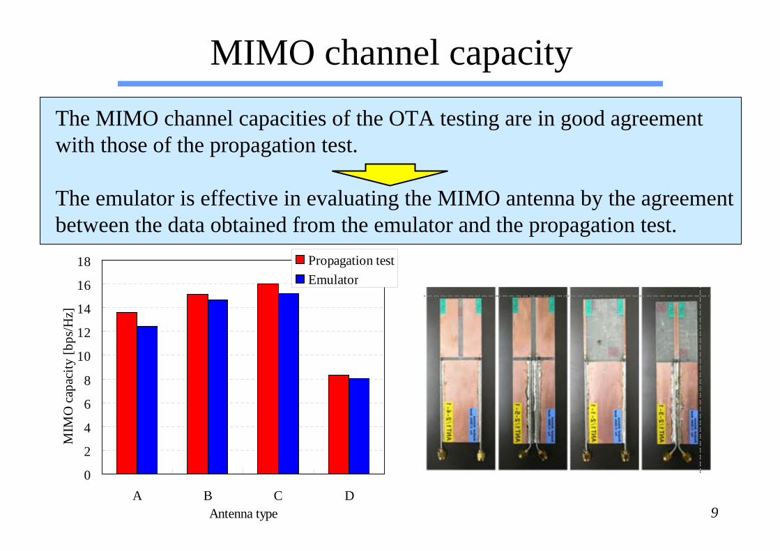
MIMO channel capacity
(A) (B) (C) (D)
0
2
4
6
8
10
12
14
16
18
A B C DAntenna type
MIM
O c
apac
ity [b
ps/H
z]
Propagation testEmulator
The MIMO channel capacities of the OTA testing are in good agreementwith those of the propagation test.
The emulator is effective in evaluating the MIMO antenna by the agreementbetween the data obtained from the emulator and the propagation test.

10
2-by-2 MIMO measurement system
For handset evaluation, we have constructed measurement system with a delay wave using a set of WLAN radio transceivers.The two digital fading simulators are used only for producing delayprofile of the incoming waves.
MS#1#2
WAP#1#2
ATTATT
ATTATT
Downlink
Uplink
DFSDiv.VPA.
Anechoic chamber
Servercomputer
Clientcomputer
Phaseshifter
Attenuator
Circulator
LO
Circulator Isolator
Spatial fading emulator for a 2-by-2 MIMO wireless LAN system

11
Measured throughput vs. delay time (fd=6Hz)The MIMO throughput is almost similar to SISO in the case of fd = 6Hz because the lowthroughput causes a change of the transmission method from MIMO to SISO.The advantage of the MIMO configuration is obtained by only the maximum ratio combining (MRC) diversity effect.
One delay wave with the same power as the direct wave.
0
10
20
30
40
50
60
70
0 200 400 600 800 1000
Delay [nsec]
TP
[M
bps]
fd=6HzWith delay
MIMOSISOMIMOSISO
Dipole array
Radio frequency: 2.412 GHz.

12
I presented an effectiveness of the RF-controlled spatial fading emulator with regard to both antenna measurment
and handset evaluation.
For antenna evaluation, the agreement between MIMO characteristics in the propagation test and OTA testing reveals that the emulator is effective in evaluating handset antennas.
With respect to handset evaluation, we have made a start ofthe MIMO throughput measurement using the emulator.
Conclusion
Top Related