


Languages
Pages
Legal


midas GTS Release NoteNext Generation Solut ion for Geotechnical and Tunnel Engineering
midas GTS 2011 Release NotesNext Generation Solut ion for Geotechnical and Tunnel Engineering

Enhancements
Pre Processing
1. Enhanced Web Authorization
2. Enhanced Line Beam Load
3. Tapered Beam considering varying depth
4. Beam End Release
Analysis
1. 2D Equivalent Linear
3
4
5
6
7
Post Processing
1. Convergence Report 9

midasGTSEnhancements midas GTS 2011 Release Notes
3 / 9
1. Web Authentication
• Web license holders can now enter their unique key number directly in the “Register Protection Key” dialogbox as opposed to visiting the web authentication page.
Pre-Processing
Modified Contents
Help > Register Protection Key
Register Protection Key

midasGTSEnhancements midas GTS 2011 Release Notes
4 / 9
• The enhanced preprocessor allows users to apply line beam loads based on the orientation of the beamelement coordinate system.
Modified Contents
• A continuous line beam load can be defined by simply selecting two points along the length of the beam.The intermediate beam elements between the two selected points are then selected and assigned either anelement or global direction.
• Line beam loads and their respective load values can be easily extracted into a table format.
Effects & Usage
Model > Load > Line Beam Load
Line Beam Load - Selected Element
Element coordinate system of Beam element
Line beam load application in the local z direction
2. Enhanced Line Beam Load

midasGTSEnhancements midas GTS 2011 Release Notes
5 / 9
3. Tapered Beam with varying depth
• The enhanced cross sectional properties dialog box can now consider Non-uniform & tapered 1D Beamelements.
Upgrade Contents
Model > Property > Property(Beam)
Taper Beam Property
• Detailed structural analysis for tunnel and wall lining, which are modelled using 1D beam elements, can nowbe analyzed with more precision by considering the actual flexural rigidity EI of the structure.
• Section Library for beam elements includes input i & j parameters with an optional tapering feature.
Effects & Usage
Section Library
Taper Section(Lining) Taper Section(Retaining Wall)

midasGTSEnhancements midas GTS 2011 Release Notes
6 / 9
4. Beam End Release added feature
• A new beam end release function is now available in GTS. This function can simulate hinge, sliding, rollerjoint, partial fixity motions.
• Directly enter either a stiffness ratio or actual stiffness value to the end constraints.
Upgrade Contents
Model > Boundary > Beam End Release
Text file
Confirming Beam End Release
Beam End Release My set to zero
• The axial force, torsion & rotational moments assigned a user defined value to either introduce partial fixityor total detachment.Nonlinear and Seepage Analysis cannot consider beam end release with partial fixity. Only full
release or fully fixed constraints can be considered.
Effects & Usage

midasGTSEnhancements midas GTS 2011 Release Notes
7 / 9
Analysis
1. 2D Equivalent linear analysis
• 2D Equivalent Linear-considering soil structural interaction (SSI)(File > Project Setting > „2D Equivalent Linear‟)
• The 2D equivalent linear analysis developed in GTS is based on the FLUSH code, which is an equivalentlinear dynamic response analysis program.
• Simple and efficient approximation of the effects of nonlinear soil behavior on the soil-structure system.• Depending on the type of analysis, nonlinear or equivalent linear, the SSI response can vary significantly. It
is necessary to obtain the correct strain values that are representative of the ground.
Upgrade Contents
Analysis > Analysis Case > Equivalent Linear(Dynamic)
• Examine soil-structure interaction, from attenuated or amplified wave propagations, for structures that areconstructed on progressively soft/weak layers such as clay layer or sandy soil.
• ground impedance, shape of foundation, strength of foundation, foundation buckling, water level , adjoiningstructures (SSI) etc. Factors that can affect the SSI: Embedded structures, characteristics of backfill,characteristics of soil layers,
Effects & Usage
Defining dynamic properties
Project Setting

midasGTSEnhancements midas GTS 2011 Release Notes
8 / 9
Analysis > Analysis Case > Equivalent Linear(Dynamic)
• In actuality, the modelling the real site ground dimensions is not practical in numerical analysis. Only theregions where structure is embedded in the ground needs to be modelled. Due to this assumption,Transmitting Boundary Conditions are applied to remove any of the reflected waves which are generatedfrom the structure.
• In order to consider the influence from body and surface waves, the shear boundary condition can beexpressed as a frequency function with springs and dampers to simulate the horizontal behavior of thesubsoil.
Effects & Usage
Transmitting Boundary Condition Converged results of shear modulus
Strain compatible property function considering the shear modulus and damping ratio

midasGTSEnhancements midas GTS 2011 Release Notes
9 / 9
1. Convergence Report
• The convergence report prints the convergence status onto a graph with respect to each stage andcorresponding step.Seepage analysis (steady-stage & transient) and consolidation analysis under development.
Post-processing
Upgrade Contents
Analysis > Solve
Convergence Report
• The Output Window is a visual aid to allow users to determine whether the solution has converged or indetail which analysis phase and load step the solution has diverged.
Effects & Usage

midas GTS Release NoteNext Generation Solution for Geotechnical and Tunnel Engineering
midas GTS 2010 v1.2 Release NotesNext Generation Solution for Geotechnical and Tunnel Engineering

Enhancements
Pre Processing
Analysis
Post Processing
• Create Interface 3
• Pile / Pile Tip Mesh Set 4
• Text file Format 5
• Mesh Preference 6
• User Supplied Material 7
• D-min Model (Japan Central Research Institute of Electric Power Industry )
7
• Initial Ground Stress 8
• Flow Interface 9
• Analysis Type : Modified Cam Clay model
10
• Spacing Input Parameter : Beam, Truss/Embedded Truss
11
• Flow Quantity 12

midasGTSEnhancement midas GTS 2010 v1.2 Release Notes
3 / 12
1. Create Interface
• Users can control the directional component, i.e. Element Coordinate System (ECS), of interface elementsthat are created using “From Plate” method.
• Automatically generates rigid link elements between nodes with full control in assigning degrees of freedom.(Create Rigid Link Element : 3D: DX, DY, DZ and 2D: DX, DY)
Pre-Processing
Modified Contents
• This function can be used to model soil to structural interaction for a wall that is embedded between two soilelements.
Effects & Usage
Model > Element > Create Interface
Create Interface – From Plate
Interface Generation
DOF assignment for Rigid Links

midasGTSEnhancement midas GTS 2010 v1.2 Release Notes
4 / 12
2. Pile / Pile Tip mesh set
• Activation of “Pile Tip Spring” generates two independent mesh sets: Pile tip springs and pile elements.• In order to reflect the Slope of Friction-Rel Disp. Curve values, the reference height is referenced from the
global coordinate system (GCS).• The graph below shows variation of shear stiffness at reference height with a user defined Slope of Friction-
Rel. Disp. Curve (relative displacement – friction curve) parameter being activated. The diagram belowshows the shear stiffness as a function of depth.
• Midas GTS v1.2 automatically creates an additional activated pile tip mesh set(s), i.e. Construction Stages,for model files that were created in previous versions of midas GTS with activated pile tip spring(s). (Pile tipsprings that are manually deactivated/removed also require corresponding mesh sets to bedeactivated/removed, i.e. Construction Stages.)
Upgrade Contents
Model > Property > Property(Pile)
Pile Interface Property
Pile Interface Mesh Set
Variation of shear stiffness at reference height

midasGTSEnhancement midas GTS 2010 v1.2 Release Notes
5 / 12
3. Text file format
• Neutral Format File *.FPN files contains the following information about a model: midas GTS versionnumber, Geometry, Attribute, Material, Property, Boundary, Load, Construction stage and Analysis types.Neutral Format Files can be viewed in any generic text reader only and imported/exported.
Upgrade Contents
File > Import, Export > Neutral Format File(*.FPN)
Export
Text file
Import
Neutral Text File Input Data File

midasGTSEnhancement midas GTS 2010 v1.2 Release Notes
6 / 12
4. Mesh Preference
• Mesh Preference options have been organized into tabs. This allows users to easily navigate between thefollowing options: General, 2D, 3D, and Pattern/Remesh.
• Consider Edge-Face Proximity matches seeding definitions from edges to faces within a predefinedproximity.
Modified Contents
Mesh > Mesh Preference
Proximity - OFF Proximity - ON
Mesh Preference Interface

midasGTSEnhancement midas GTS 2010 v1.2 Release Notes
7 / 12
User supplied material
1. User Supplied Material
• User Supplied Material allows users to develop Fortran material models for nonlinear elastic and plasticbehavior.
Modified Contents
Model > Property > Material
2. D-min model
• The D-min model was developed by Hayashi, Hibino in Japan Central Research Institute of Electric PowerIndustry (CRIEPI).
• D-min model assumes linear elastic characteristics where the material stiffness is updated incrementally inevery construction stage while the material stiffness remains constant during each stage.
Upgrade Contents
D-min model
Analysis

midasGTSEnhancement midas GTS 2010 v1.2 Release Notes
8 / 12
Prestress Interface
3. Initial Prestress Input
• The option to „Do not Make Displacement‟ clears any deformation when assigning a prestress load set to anelement.
Upgrade Contents
Model > Load > Prestress
• Applying an initial prestress to an element can have two effects: either remain static without any stressreduction or recalculate initial conditions to find the equilibrium stress states. (Similar experimentalconditions and analysis results can be simulated)
Effects & Usage
X-direction : Sxx
‘Do not Make Displacement (Deactivated)
X-direction : Sxx
‘Do not Make Displacement (Activated)

midasGTSEnhancement midas GTS 2010 v1.2 Release Notes
9 / 12
Interface Dialog
4. Flow Interface
• Interface Elements can be defined with a permeability parameter to allow flow.(If the interface element nodes are not separated, an error will occur upon calling the solver. Users mustensure that the nodes have been properly separated.)
• Simulate the flow between two nodes and head boundary conditions using elastic and rigid links. Elasticand rigid link elements can be modeled and assigned either a permeability coefficient for seepage flow andseepage flow DOF.
Upgrade Contents
Model > Property > Property > Interface , Rigid Link , Elastic Link
• Simulate soil to structure interaction by modeling interface elements with option to consider groundwater.
Effects & Usage
Flow Interface - OFF
Elastic Link DialogRigid Link Dialog
Flow Interface - ON

midasGTSEnhancement midas GTS 2010 v1.2 Release Notes
10 / 12
5. Analysis Type Modified Cam Clay model
• When using Modified Cam-Clay for analysis types non-linear, construction stage non-linear, and seepageanalysis the input parameter “Initial void ratio” is required.
• Analysis types other than the aforementioned cases, only the “Critical State Specific Vol” input parameter isrequired.
Modified Contents
Model > Attribute > Material > Modified Cam Clay
Modified Cam Clay model
Initial void ratio Critical State Specific Vol.
Analysis Type
• Nonlinear Static• Construction Stage (Construction, Steady State, Transient)• Seepage (Steady State)• Seepage (Transient)
• Linear Static• Construction Stage(Consolidation)
• Consolidation• Slope Stability (SRM, SAM)• Eigenvalue• Response Spectrum• Time History(Linear)
Parameter definition for Analysis Types

midasGTSEnhancement midas GTS 2010 v1.2 Release Notes
11 / 12
1. Spacing input parameter : Beam, Truss/Embedded Truss
• In 2D modeling, spacing can be considered for Beam, Truss/Embedded Truss elements. Results areautomatically outputted under their respective label. (Spacing does not apply to 3D modeling)
Modified Contents
Model > Property > Property > Truss/Embedded Truss, Beam/Nonlinear Beam
Property Dialog
No Spacing – Beam Fx Spacing – Beam Fx
• Beam Fx : (Max #) ⅹ (Spacing) = -14.89 ⅹ 2 = -29.78 tonf
• Beam Fx : Max #= -29.78 tonf
Property Dialog

midasGTSEnhancement midas GTS 2010 v1.2 Release Notes
12 / 12
1. Flow Quantity
• After performing a seepage analysis, users can manually enter Node ID to confirm the flow quantity values.
Post-processing
Modified Contents
1. Node Selection Method
Result > Seepage Result > Flow Quantity
2. Manual Selection

midas GTS Release NoteNext Generation Solut ion for Geotechnical and Tunnel Engineering
midas GTS 2010 v1.1 Release NotesGeotechnical and Tunnel Analysis System

Enhancements
Pre Processing
Analysis
1. File Preview & Status Bar
2. Project Settings
3. Works Tree Features
4. Check Note Feature
5. Check Mesh Feature
6. Divide Mesh Set by Surface
7. Gauging Element Feature
8. Seepage Face
9. Water Level for Mesh Set
10. Anchor Modeling Wizard
1. 1D Equivalent Linear Analysis
2. Analysis Speed Improvement
3. Upgrade Iterative Methods
4. High Order Beam Element
5. Mohr-Coulomb model Tension Cut-off
5
6
7
8
9
10
11
12
13
14
15
16
17
18
19

Enhancements
Post Processing
6. Steady state Seepage effects in Stress-seepage semi coupled Analysis
7. Interface / Pile Elements in Dynamic Analysis
8. Permeability Coefficient Range
9. Automatic Consideration of Hydrostatic Pressure
10. Convergence Criterion in Non-linear and Construction Stage Analysis
11. Output Format for Nonlinear, Construction Stage and
Seepage Analysis Results
1. Opening Analysis Results File
2. Enhancement in Post Processing - Graphics Performance
3. 1D (Beam / Truss) Element Axial Force Output
4. Beam Element Coordinate System (2D Modeling)
5. Seepage-Stress Coupled Analysis Results
6. Consolidation Analysis Results
7. Time History Analysis Results
8. Clipping Plane
9. Combination / Envelope Results
19
19
20
20
21
22
23
24
25
26
27
28
29
30
31

Enhancements
Remarks in GTS2010
10. Table Output of Analysis Results
11. Analysis Case Combinations and Result Component
Combination
12. Table Output for Summation of Reactions
13. Report Function Removed
14. Result Function Removed
15. Cam Clay Model Removed
32
33
33
33
33
34
midasGTSEnhancements midas GTS 2010 v1.1 Release Notes
5 / 34
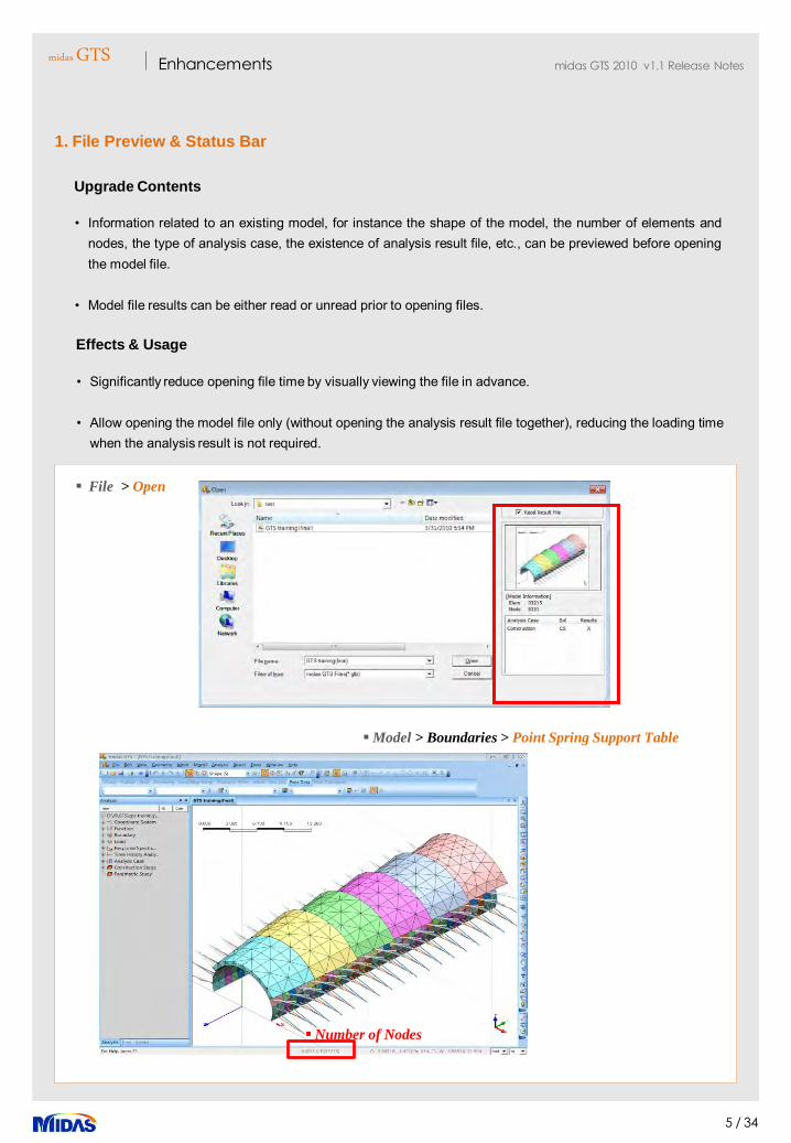
1. File Preview & Status Bar
• Information related to an existing model, for instance the shape of the model, the number of elements andnodes, the type of analysis case, the existence of analysis result file, etc., can be previewed before openingthe model file.
• Model file results can be either read or unread prior to opening files.
Upgrade Contents
• Significantly reduce opening file time by visually viewing the file in advance.
• Allow opening the model file only (without opening the analysis result file together), reducing the loading timewhen the analysis result is not required.
Effects & Usage
File > Open
Model > Boundaries > Point Spring Support Table
Number of Nodes

midasGTSEnhancements midas GTS 2010 v1.1 Release Notes
6 / 34
File > Project Setting
2. Project Settings
• Model types of 2D and Axisymmetric have analysis constraints fixed in X-Y plane only. As a result, thegravity direction is fixed in the Y-direction.
• Model files created in previous versions of GTS with different analysis constraints will automatically updatethe loads, boundary conditions, and geometry definitions to be compatible in GTS 2010 V1.1 environment.Message box will appear to indicate any changes.
Modified Contents
Project Settings (V300)
Project Settings (GTS V1.1)
Warning Message (GTS V1.1)

midasGTSEnhancements midas GTS 2010 v1.1 Release Notes
7 / 34
3. Works Tree Feature
• Friendly graphical user interface that enables users to access data more readily.
• Newly added features such as “color coding” system and checkboxes for better data handling.
* Automatic report not supported, accordingly Report Works removed (in a later version, new Report function
will be supported)
Upgrade Contents
Model, Analysis, Post-Works Tree
• An improved management GUI that separates the modeling, analysis, and post processor data. Theseitems can accessed quickly by clicking feature tabs.
• Mesh set management provides easier work control (auto-grouping, modification by group, show/hide, etc.)and Property window. Note : Due to this feature, “Register Each Solid Independently” has been removed.
Effects & Usage

midasGTSEnhancements midas GTS 2010 v1.1 Release Notes
8 / 34
Model > Boundaries > Point Spring Support Table
4. Check Note Feature
• Snapshots of a model can be saved and managed in the Model-Works Tress.
• In the Check note environment, markups and comments can be made for better QA/QC procedure.
Upgrade Contents
Model-Works Tree > Check Note
Check Note
• Enable easy management of models for later review, by capturing and saving important parts
• Easily report technical support by directly sending an email from the software (no need to capture a screenor to describe a problem)
Effects & Usage

midasGTSEnhancements midas GTS 2010 v1.1 Release Notes
9 / 34
Mesh > Check Mesh > Clamped Element(Purple)
5. Check Mesh Feature
Generated Model
Clamped Element verification
• New “Check Mesh” feature enables to identify clamped elements in 3D elements specifically used for CFDanalysis.
Upgrade Contents
• Thinnest 3D elements along the outer edges are identified. For proper CFD modeling the clamped elementsmust be refined in order to obtain accurate results.
Effects & Usage
Check Mesh – Clamped Element
midasGTSEnhancements midas GTS 2010 v1.1 Release Notes
10 / 34
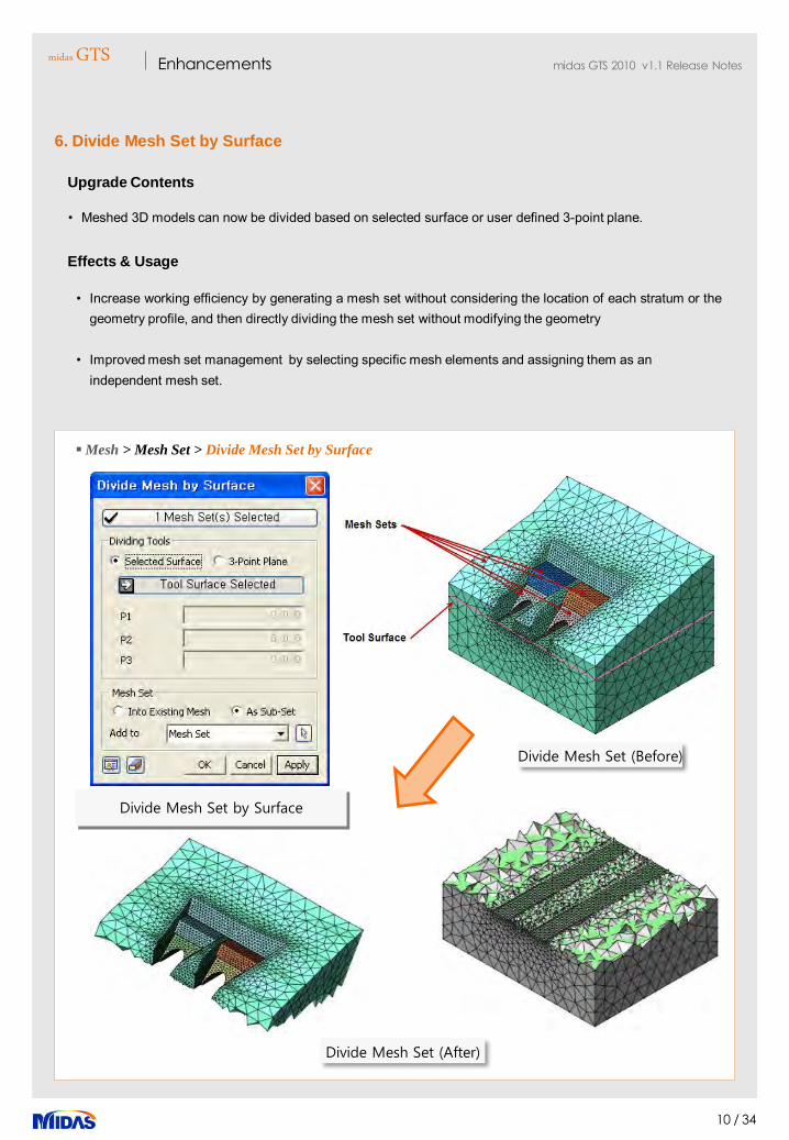
Mesh > Mesh Set > Divide Mesh Set by Surface
6. Divide Mesh Set by Surface
• Meshed 3D models can now be divided based on selected surface or user defined 3-point plane.
Upgrade Contents
Divide Mesh Set (Before)
Effects & Usage
• Increase working efficiency by generating a mesh set without considering the location of each stratum or thegeometry profile, and then directly dividing the mesh set without modifying the geometry
• Improved mesh set management by selecting specific mesh elements and assigning them as an independent mesh set.
Divide Mesh Set (After)
Divide Mesh Set by Surface

midasGTSEnhancements midas GTS 2010 v1.1 Release Notes
11 / 34
Model > Element > Create Gauging Element
7. Gauging Element Feature
각 요소망에 지하수위 정의
Gauging Element Generation
Gauging Element Results
• Gauging Element feature supports extracting structural elements (referred to gauging element) from 3D solids.
• Gauging elements can be used to assess member forces, which cannot be checked from the 3D solids.
Upgrade Contents
• In a 3D model, gauging elements from a solid can be assigned a gauging element property in order to assess moments and shear forces.
Effects & Usage

midasGTSEnhancements midas GTS 2010 v1.1 Release Notes
12 / 34
Model > Boundary > Seepage Face
8. Seepage Face
• Model > Boundary > Seepage Face has replaced „Review Boundary based on Seepage Conditions‟ under„Nodal Flux Boundary‟.
Upgrade Contents
Review Boundary(V300)
• Pressure head value defines a review boundary which will allow the solver to determine the appropriatenodes that have flow or no flow.
• This feature can either be applied to the geometry or element level.
Usage
Seepage Face(V1.1)

midasGTSEnhancements midas GTS 2010 v1.1 Release Notes
13 / 34
Model > Construction Stage > Define Construction Stage
9. Water Level for Mesh Set
• Support a separate water level for each mesh set.
• Support spatial variation of water level along construction stages.
Upgrade Contents
Each mesh set water level Definition
Confined/Unconfined aquifer layers
• Enables modeling of dewatering inside excavations in a friendly manner• Enables assignment of water level per stratum that is useful confined aquifer modeling.
Effects & Usage

midasGTSEnhancements midas GTS 2010 v1.1 Release Notes
14 / 34
10. Anchor Modeling Wizard
• Support Anchor Modeling Wizard in 2D and 3D models
Upgrade Contents
Model > Anchor Modeling Wizard
Upside-down T-shape section L-shape section
Anchor Wizard
Anchor model
• Provide easy modeling of anchor (no need for geometric modeling)
• Automatically generate mesh using input data, from one dialogue box, for material, section, angle, ungroutedlength, grouted length, etc.
• Prevent singular error during analysis by automatically generating the mesh in the form of an EmbeddedTruss.
Effects & Usage

midasGTSEnhancements midas GTS 2010 v1.1 Release Notes
15 / 34
Analysis
1. 1D Equivalent Linear Analysis
• Support ground response analysis using 1D equivalent linear analysis
• Support Free Field analysis (response analysis of unexcavated ground, where no structure is constructed )
Upgrade Contents
Tool > Free Field Analysis
Strain Compatible Property Function
• Useful for estimating ground vibration, calculating dynamic stress and strain for liquefaction evaluation, anddetermining seismic load
• Obtain essential data for seismic analysis by offering the same analysis functions as Shake-type software
Effects & Usage
Preview of Ground Layers Ground layer formulation
Stress-strain graph

midasGTSEnhancements midas GTS 2010 v1.1 Release Notes
16 / 34
Analysis Option
2. Analysis Speed Improvement
• Support 64-bit OS & multi-core parallel system in nonlinear, construction-stage and seepage analysis
Upgrade Contents
Analysis > Analysis Option
• Provide improved analysis performance using Multi-Frontal Sparse Gaussian Solver
• Substantially increase analysis speed for large models (usually 2 to 3 times faster than V300) by utilizing thefull RAM memory available for 64-bit systems.
Effects & Usage
FE Solid Element(Hexa Mesh)
Analysis case
Ground with self weight
# Element 27,000(Model 1), 64,000(Model 2)
BC Ground support Boundary conditions
Load Self weight
Model 1 Model 2

midasGTSEnhancements midas GTS 2010 v1.1 Release Notes
17 / 34
3. Upgrade Iterative methods
• The following iterative methods can be used with load steps for nonlinear iteration analysis.• Arc Length Method• Secant stiffness method• Modified Newton-Raphson method
Upgrade Contents
Analysis > Nonlinear Analysis Option
Nonlinear Control panel
Analysis case per iteration method
• Improve solver convergence and enhance analysis speed in nonlinear analysis
Effects & Usage
midasGTSEnhancements midas GTS 2010 v1.1 Release Notes
18 / 34
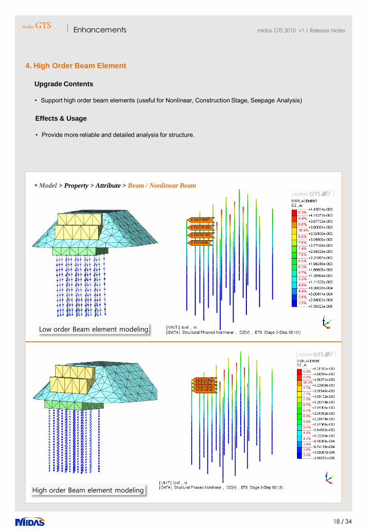
Model > Property > Attribute > Beam / Nonlinear Beam
4. High Order Beam Element
• Support high order beam elements (useful for Nonlinear, Construction Stage, Seepage Analysis)
Upgrade Contents
• Provide more reliable and detailed analysis for structure.
Effects & Usage
Low order Beam element modeling
High order Beam element modeling
midasGTSEnhancements midas GTS 2010 v1.1 Release Notes
19 / 34
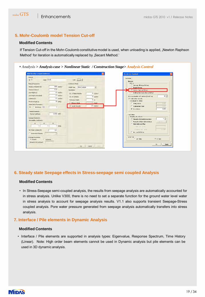
Analysis > Analysis case > Nonlinear Static / Construction Stage> Analysis Control
5. Mohr-Coulomb model Tension Cut-off
If Tension Cut-off in the Mohr-Coulomb constitutive model is used, when unloading is applied, „Newton Raphson Method‟ for iteration is automatically replaced by „Secant Method.‟
Modified Contents
7. Interface / Pile elements in Dynamic Analysis
Modified Contents
• Interface / Pile elements are supported in analysis types: Eigenvalue, Response Spectrum, Time History(Linear). Note: High order beam elements cannot be used in Dynamic analysis but pile elements can beused in 3D dynamic analysis.
6. Steady state Seepage effects in Stress-seepage semi coupled Analysis
• In Stress-Seepage semi-coupled analysis, the results from seepage analysis are automatically accounted forin stress analysis. Unlike V300, there is no need to set a separate function for the ground water level waterin stress analysis to account for seepage analysis results. V1.1 also supports transient Seepage-Stresscoupled analysis. Pore water pressure generated from seepage analysis automatically transfers into stressanalysis.
Modified Contents

midasGTSEnhancements midas GTS 2010 v1.1 Release Notes
20 / 34
Analysis > Analysis case > Nonlinear Static / Construction Stage
9. Automatic Consideration of Hydrostatic Pressure in 2D and 3D Modeling
Modified Contents
Case 1
Case 2
8. Permeability Coefficient Range
• Support unlimited permeability coefficient. In V300, the permeability coefficient needed to be greater than1.00E-08.
Modified Contents
• When the water table lies above the ground surface (e.g. dams) or if it lies outside the model (e.g. floodedexcavation), a line pressure corresponding to the water lying outside the model is added automatically alongthe model boundary to equilibrate the volume pressure load.
midasGTSEnhancements midas GTS 2010 v1.1 Release Notes
21 / 34
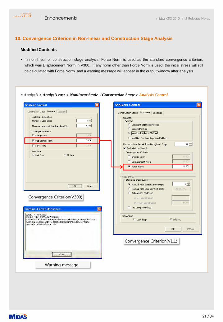
Analysis > Analysis case > Nonlinear Static / Construction Stage > Analysis Control
Convergence Criterion(V300)
Convergence Criterion(V1.1)
10. Convergence Criterion in Non-linear and Construction Stage Analysis
• In non-linear or construction stage analysis, Force Norm is used as the standard convergence criterion,which was Displacement Norm in V300. If any norm other than Force Norm is used, the initial stress will stillbe calculated with Force Norm ,and a warning message will appear in the output window after analysis.
Modified Contents
Warning message

midasGTSEnhancements midas GTS 2010 v1.1 Release Notes
22 / 34
.OUT File GTS V300
11. Output Format for Nonlinear, Construction Stage and Seepage Analysis Results
• Output format for Nonlinear, Construction Stage and Seepage analysis results has been modified toexplicitly include details about the load step, convergence status and general details about the convergencecriterion.
Modified Contents
.OUT(V1.1)
.OUT(V300)
Construction stage
Regardless of the convergence status, the analysis continues until the maximum number of load steps havebeen reached. No indication aboutConvergence is shown in the output file.
The convergence status is indicated by a check label whichdisplays either a True/False value.

midasGTSEnhancements midas GTS 2010 v1.1 Release Notes
23 / 34
1. Opening Analysis Result File
Post-processing
Modified Contents
Post works tree
Post works tree – Context Menu
Opening result file .gpb
Add result file
• Result files that have been generated in V300 cannot be opened by V1.1. The model file needs to bereanalyzed by V1.1.
• After performing analysis in V1.1, if the results are not displayed on the Post works tree, the result file can bemanually opened as illustrated below.

midasGTSEnhancements midas GTS 2010 v1.1 Release Notes
24 / 34
Post-processing > Post Data
2. Enhancement in Post Processing - Graphics Performance
• In V1.1, Post Process Graphics performance enhanced
Upgrade Contents
Displacement benchmark Stress benchmark
• Enable fast check of analysis results
• Provide 2 to 3 times faster work for a large model compared to the previous version (up to 50 times fasterdepending on the model size)
Effects & Usage
Model 1 Model 2
# Nodes # Element # Nodes # Element
Approx 320,000 Approx 170,000 Approx 360,000 Approx 200,000
midasGTSEnhancements midas GTS 2010 v1.1 Release Notes
25 / 34
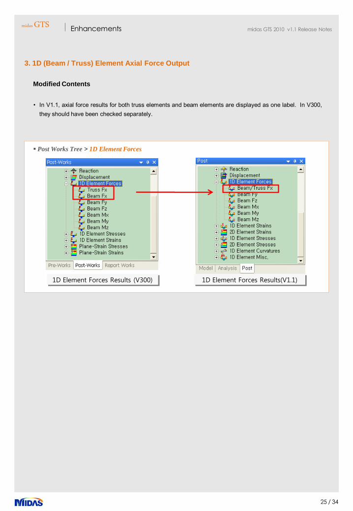
3. 1D (Beam / Truss) Element Axial Force Output
• In V1.1, axial force results for both truss elements and beam elements are displayed as one label. In V300,they should have been checked separately.
Modified Contents
Post Works Tree > 1D Element Forces
1D Element Forces Results (V300) 1D Element Forces Results(V1.1)

midasGTSEnhancements midas GTS 2010 v1.1 Release Notes
26 / 34
4. Beam Element Coordinate System (2D Modeling)
• The working plane in 2D modeling is only defined in the X-Y plane. Accordingly, the beam elementcoordinate system is used for X-Z axes only
Modified Contents
Post-Works Tree > 1D Element Force
Beam Element (V300)
Bending Moment Results (V300)-Beam Mz
Beam Element (V1.1)
Bending Moment Results (V1.1)-Beam My
• In V300, bending moment results for beam elements were checked using My or Mz, depending on theelement coordinate system. In V1.1, however, the bending moment results can be checked only through „1DElement Forces > Beam My.‟
Usage

midasGTSEnhancements midas GTS 2010 v1.1 Release Notes
27 / 34
5. Seepage-Stress Coupled Analysis Results
• In the Post works tree, the order of results for Seepage-Stress analysis was modified. In V1.1, the resultsare first arranged according to the analysis type, whereas the results were first arranged according to theconstruction stage in V300.
Modified Contents
Post Works Tree > Seepage-Stress Coupled Analysis
Post works tree(V300) Post works tree(V1.1)
Seepage-Stress Coupled Analysis
midasGTSEnhancements midas GTS 2010 v1.1 Release Notes
28 / 34
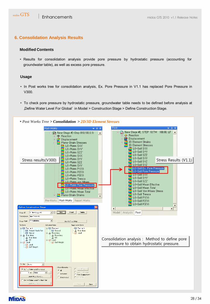
6. Consolidation Analysis Results
• Results for consolidation analysis provide pore pressure by hydrostatic pressure (accounting forgroundwater table), as well as excess pore pressure.
Modified Contents
• In Post works tree for consolidation analysis, Ex. Pore Pressure in V1.1 has replaced Pore Pressure inV300.
• To check pore pressure by hydrostatic pressure, groundwater table needs to be defined before analysis at„Define Water Level For Global‟ in Model > Construction Stage > Define Construction Stage.
Usage
Consolidation analysis : Method to define pore pressure to obtain hydrostatic pressure.
Post Works Tree > Consolidation > 2D/3D Element Stresses
Stress results(V300) Stress Results (V1.1)

midasGTSEnhancements midas GTS 2010 v1.1 Release Notes
29 / 34
7. Time History Analysis Results
• Velocity and Acceleration labels were added to the results for Time History analysis.
Modified Contents
Time History Analysis Results (V300)
Time History Analysis Results (V1.1)
Post Works Tree > Time History(Linear) > Velocity, Acceleration

midasGTSEnhancements midas GTS 2010 v1.1 Release Notes
30 / 34
8. Clipping Plane
• Union (new in V1.1) of the clipping planes, as well as Intersection (same as in V300), is available.
Modified Contents
Property Window > Clipping Plane
Clipping Plane - Intersection
Intersection Results
Clipping Plane - UnionUnion results

midasGTSEnhancements midas GTS 2010 v1.1 Release Notes
31 / 34
9. Combination / Envelope Results
• Combination/ Envelope Results supports Linear combination of load sets , i.e. temperature, pressure
loads etc.
Upgrade Contents
Result > Combination /Envelope Results
• Consider various types of loading environment for lining design specifications.
• Provides ADD or an envelope for each load combination
Effects & Usage

midasGTSEnhancements midas GTS 2010 v1.1 Release Notes
32 / 34
10. Table Output of Analysis Results
• „Result > Result Table‟ in V300 was removed. In V1.1, table output for analysis results can be checked usingthe Context Menu of each result item in Post works tree.
• The table output format for „Result > Vibration Mode Shape‟ was renewed in V1.1.
Modified Contents
Post-Works Tree > Context Menu > Table
Result Table(V300)
Beam Mz 결과
Result Table(V1.1)
Vibration Mode Shape Table Output

midasGTSEnhancements midas GTS 2010 v1.1 Release Notes
33 / 34
12. Table Output for Summation of Reactions
• „Result > Result Table > Reaction‟ in V300 was replaced by „Result > Summation of Reactions‟ in V1.1.(In V1.1, the table output for the sum of reactions is checked in a separate dialog box, not in the work window.)
Modified Contents
Result > Summation of Reactions
Beam Mz 결과
V1.1 – Result Table
Summation of Reactions
11. Analysis Case Combinations and Result Component Combination
• „Result > Analysis Case Combinations‟ and „Result > Result Component Combination‟ in V300 werereplaced by „Result > Result Calculation‟ in V1.1.
Modified Contents
13. Report Function Removed
• „Result > Result Summary„in V300 was removed in V1.1. (Next release will support new Report function.)
Modified Contents
14. Result Function Removed
• In V300, „Result > Result Function‟ predetermined, before running analysis, the contents to be checked afteranalysis. This function was removed in V1.1 because all results can be checked after analysis using „Result> Extract Result.‟
Modified Contents

midasGTSEnhancements midas GTS 2010 v1.1 Release Notes
34 / 34
GTS V300 GTS V1.1
15. Cam Clay Model
• No longer support the Cam Clay constitutive model. Instead, the Modified Cam Clay constitutive model isrecommended.
Modified Contents
Model > Property > Material > Ground Material
Top Related