


Languages
Pages
Legal


05/01/2023 GSM CONTROLLED ROBOTIC VEHICLE 1
GSM CONTROLLED ROBOTIC VEHICLE
GROUP 1: MOHAMMED NIHAL (14) SABAH MURSAL (22) KARTHIKA (10) SUDHEESH (37)
Guided By:Shekeela M.AAssistant ProfessorAE&I

05/01/2023 GSM CONTROLLED ROBOTIC VEHICLE 2
CONTENTS Objectives Introduction Block diagram Description Circuit diagram Circuit description Components description Flow chart Work done Result and output References

05/01/2023 GSM CONTROLLED ROBOTIC VEHICLE 3
OBJECTIVES
• The objective of our project is to design a
remote controlled robot (using cell phone as a
remote).
• The movement of the robot is done by sending
different commands from our cell phone.
05/01/2023 GSM CONTROLLED ROBOTIC VEHICLE 4
INTRODUCTION
Wireless controlled robots use RF circuits , which have the drawbacks of limited working range , limited frequency range and limited control.
Use of a mobile phone for robotic control can overcome these limitations.
The control of robot involves three distinct phases: reception, processing and action.

05/01/2023 GSM CONTROLLED ROBOTIC VEHICLE 5
Cont….
Generally, the receptors are sensed by IC HT9107B mounted on the robot.
Processing is done by the on-board microcontroller Atmega 16.
Task(movement to forward,backward etc.) is performed using motors or with some other actuators.
……………………

05/01/2023 GSM CONTROLLED ROBOTIC VEHICLE 6
BLOCK DIAGRAM
POWER SUPPLY

05/01/2023 GSM CONTROLLED ROBOTIC VEHICLE 7
BLOCK DIAGRAM DESCRIPTION
Cell phone act as a DTMF generator with tone depending upon the key pressed.
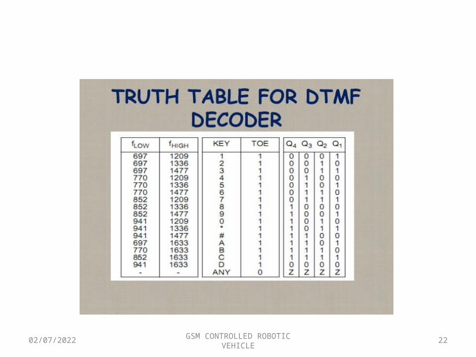
DTMF Decoder [IC HT9107B] decodes the received tone and gives binary equivalent of it to the microcontroller [ATmega16].
05/01/2023 GSM CONTROLLED ROBOTIC VEHICLE 8
Cont…• The ATmega16 controller is programmed such
that appropriate output is given to Motor Driver IC L293D .
• IC L293D will drive the two DC Motors connected to it.
• So, ultimately the two motors rotate according to the key pressed on the keypad of the cell.

05/01/2023 GSM CONTROLLED ROBOTIC VEHICLE 9
CIRCUIT DIAGRAM
05/01/2023 10
COMPONENTS REQUIRED: IC1 – HT9107B DTMF decoder
IC2 – ATmega16 IC3 - L293D motor driver
D1 - 1N4007 rectif ier diode R1 -330-kilo-ohm R2-10-kilo-ohm
R3 - 100-kilo-ohm R4-R8 - 10-kilo-ohm
C1,C2 – 100nF C3, C4– 1nF
XTAL1 - 3.57MHz crystal XTAL2 - 12MHz crystal
M1, M2 - 6V, 50-rpm geared DC motor
GSM CONTROLLED ROBOTIC VEHICLE

05/01/2023 GSM CONTROLLED ROBOTIC VEHICLE 11
COMPONENTS DESCRIPTION
DTMF Decoder• HT9170 is the series of Dual Tone Multi
Frequency (DTMF) receivers.• HT9170 IC detects and decodes the 16 DTMF
tones into 4 bit output.• If tones are not detected, the four output bits
remain low.

05/01/2023 GSM CONTROLLED ROBOTIC VEHICLE 12
Cont… ATmega16• The atmega16 is a 8-bit microcontroller, has 64 KB
Flash microcontroller with 1 KB RAM.• it provides the following features: 1. 64 KB of on-chip Flash program memory with ISP
(In-System Programming) and IAP (In-Application Programming) .
2. Four 8-bit I/O ports with three high-current Port 1 pins (16 mA each)
3. Three 16-bit timers/counters

05/01/2023 GSM CONTROLLED ROBOTIC VEHICLE 13
Cont…
• Motor Driver IC L293D• L293D is a typical Motor driver or Motor
driver IC which allows DC motor to drive on either direction.
• L293D is a 16-pin IC which can control a set of two DC motors simultaneously in any direction.
• The L293D can drive small and quite big motors as well.

05/01/2023 GSM CONTROLLED ROBOTIC VEHICLE 14
In this project, the robot is controlled by a mobile phone that makes a call to the mobile phone attached to the robot.
In the course of a call, if any button is pressed, a tone corresponding to the button pressed is heard at the other end of the call.
This tone is called ‘dual tone multiple frequency’ (DTMF) tone.
The robot perceives this DTMF tone with the help of the phone stacked in the robot.

05/01/2023 GSM CONTROLLED ROBOTIC VEHICLE 15
The received tone is processed by the ATmega 16 microcontroller with the help of DTMF decoder MT8870.
The decoder decodes the DTMF tone into it’s equivalent binary digit and this binary number is sent to the microcontroller.

05/01/2023 GSM CONTROLLED ROBOTIC VEHICLE 16
The Atmega 16 microcontroller is programmed to take a decision to motor drivers in order to drive the motors for forward or backward motions or a turn.
The mobile that makes a call to the mobile phone stacked in the robot acts as a remote.
So this simple robotic project does not require the construction of receiver and transmitter units.

05/01/2023 GSM CONTROLLED ROBOTIC VEHICLE 17
Dual-Tone Multi-Frequency [DTMF]
DTMF Generator and Receiver• Here we use mobile phones as DTMF generator
and receiver.• One of the phone is used as a DTMF generator
which acts as a remote to control the vehicle. • The other phone acts as a receiver which receives
the DTMF tone and hand over it to the DTMF decoder IC.
05/01/2023 GSM CONTROLLED ROBOTIC VEHICLE 18
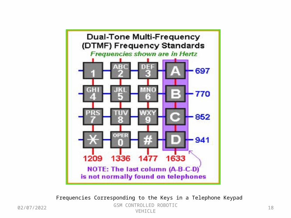
Frequencies Corresponding to the Keys in a Telephone Keypad

05/01/2023 GSM CONTROLLED ROBOTIC VEHICLE 19
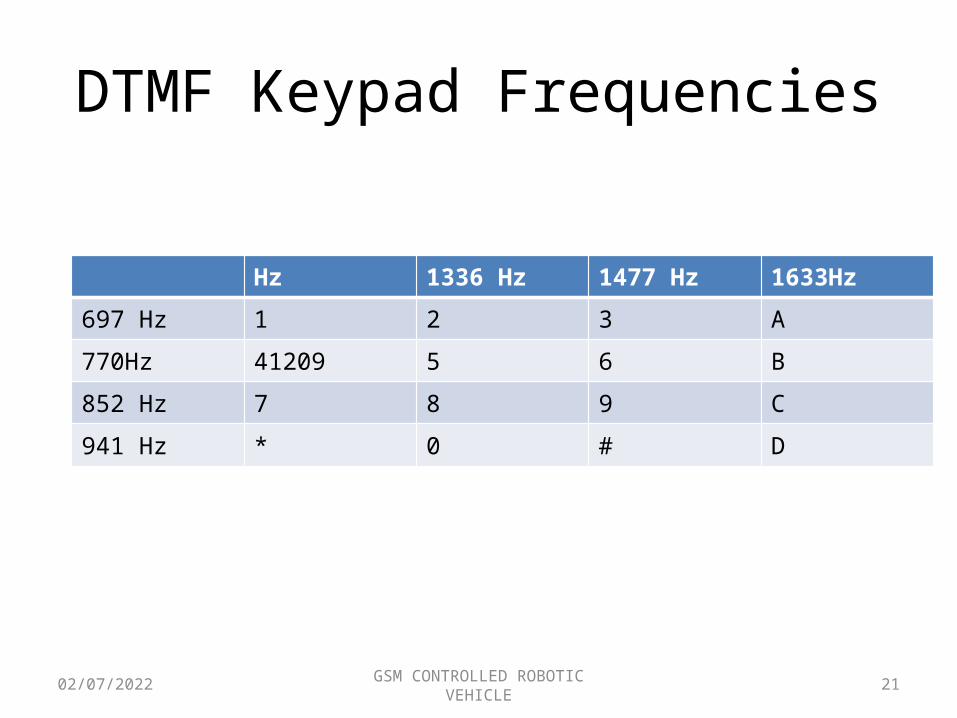
• In the dial pad, the corresponding frequencies are associated with each key.
• Whenever a key is pressed two frequencies are generated.
• The resultant tone is the combination of the two frequencies generated.
• The frequency varies from key to key corresponding to the row and column in which the key is present.

05/01/2023 GSM CONTROLLED ROBOTIC VEHICLE 20
• Each column and row has a frequency associated to it.
• For example, pressing the !1! key will result in a sound composed of both a 697 and a 1209 hertz (Hz) tone.
• These tones are then decoded by the switching center to determine which key was pressed.
05/01/2023 GSM CONTROLLED ROBOTIC VEHICLE 21
DTMF Keypad Frequencies
Hz 1336 Hz 1477 Hz 1633Hz697 Hz 1 2 3 A
770Hz 41209 5 6 B
852 Hz 7 8 9 C
941 Hz * 0 # D
05/01/2023 GSM CONTROLLED ROBOTIC VEHICLE 22

05/01/2023 GSM CONTROLLED ROBOTIC VEHICLE 23
FLOW CHART
05/01/2023 GSM CONTROLLED ROBOTIC VEHICLE 24
WORK DONE
• Design the required program.• Design the desired circuit to a bread board.• Downloaded the required software.• Converted program code to hex code

05/01/2023 GSM CONTROLLED ROBOTIC VEHICLE 25
RESULTS AND OUTPUT
Successfully connected the circuit and verified the desired output

05/01/2023 GSM CONTROLLED ROBOTIC VEHICLE 26
REFERENCE
o http://www.instructables.com/o http://www.alldatasheet.com/datasheet-pdf/pdf/
78532/ATMEL/ATMEGA16.html

05/01/2023 GSM CONTROLLED ROBOTIC VEHICLE 27
THANK YOU