


Languages
Pages
Legal


GROUP 52B
SUPPLEMENTAL RESTRAINT
SYSTEM (SRS)CONTENTS
GENERAL INFORMATION . . . . . . . . 52B-3
SERVICE PRECAUTIONS. . . . . . . . . 52B-5
SPECIAL TOOLS. . . . . . . . . . . . . . . . 52B-8
TEST EQUIPMENTS . . . . . . . . . . . . . 52B-9
TROUBLESHOOTING . . . . . . . . . . . . 52B-10DIAGNOSIS TROUBLESHOOTING FLOW . . . . . . . . . . . . . . . . . . . . . . . . . . . . . 52B-10DIAGNOSIS FUNCTION. . . . . . . . . . . . . . . 52B-10SRS WARNING LAMP CHECK . . . . . . . . . 52B-10CHECK CHART FOR DIAGNOSIS CODES . . . . . . . . . . . . . . . . . . . . . . . . . . . . 52B-11DIAGNOSTIC TROUBLE CODE PROCEDURES. . . . . . . . . . . . . . . . . . . . . . 52B-14CHECK CHART FOR TROUBLE SYMPTOMS . . . . . . . . . . . . . . . . . . . . . . . . 52B-131SYMPTOM PROCEDURES . . . . . . . . . . . . 52B-132
POST-COLLISION DIAGNOSIS. . . . . 52B-136
INDIVIDUAL COMPONENT SERVICE. . . . . . . . . . . . . . . . . . . . . . . 52B-139
WARNING/CAUTION LABELS . . . . . 52B-140
FRONT IMPACT SENSORS. . . . . . . . 52B-141REMOVAL AND INSTALLATION . . . . . . . . 52B-141INSPECTION. . . . . . . . . . . . . . . . . . . . . . . . 52B-142
SRS CONTROL UNIT (SRS-ECU) . . . 52B-143REMOVAL AND INSTALLATION . . . . . . . . 52B-143INSPECTION. . . . . . . . . . . . . . . . . . . . . . . . 52B-144
Continued on next page
WARNING• Carefully read and observe the information in the SRS SERVICE PRECAUTIONS prior to any service.• For information concerning diagnosis or maintenance, alays observe the procedures in the SRS Diagnosis or the
SRS Maintenance sections, respectively.• If any SRS components are removed or replaced in connection with any service procedures, be sure to follow the
procedures in the INDIVIDUAL COMPONENT SERVICE section for the componentnts involved.• If you have any questions about the SRS, please contact the MMNA Tech Line.

52B-2
DRIVER'S AND PASSENGER'S (FRONT) AIR BAG MODULES AND CLOCK SPRING . . . . . . . . . . . . 52B-145
REMOVAL AND INSTALLATION . . . . . . . . 52B-145INSPECTION . . . . . . . . . . . . . . . . . . . . . . . 52B-151
SIDE AND CURTAIN AIR BAG MODULES . . . . . . . . . . . . . . . . . . . . . 52B-152
REMOVAL AND INSTALLATION . . . . . . . . 52B-152INSPECTION . . . . . . . . . . . . . . . . . . . . . . . 52B-155
SIDE IMPACT SENSOR . . . . . . . . . . . 52B-157REMOVAL AND INSTALLATION . . . . . . . . 52B-157INSPECTION. . . . . . . . . . . . . . . . . . . . . . . . 52B-158
SEAT BELTS WITH PRE-TENSIONER. . . . . . . . . . . . . . . . 52B-159
REMOVAL AND INSTALLATION . . . . . . . . 52B-159INSPECTION. . . . . . . . . . . . . . . . . . . . . . . . 52B-161
AIR BAG MODULE AND SEAT BELT PRE-TENSIONER DISPOSAL PROCEDURES . . . . . . . . . . . . . . . . . . 52B-162

GENERAL INFORMATIONSUPPLEMENTAL RESTRAINT SYSTEM (SRS) 52B-3
GENERAL INFORMATIONM1524000101186
The Supplemental Restraint System (SRS) and seat belt with pre-tensioner is designed to supplement the driver's and passenger's (front) seat belts to help reduce the risk or severity of injury to the driver and front passenger by activating and deploying both front air bags in certain frontal collisions.The SRS consist of six air bag modules, SRS air bag control unit (SRS-ECU), front impact sensors, side impact sensors, SRS warning lamp, clock spring and seat belt pre-tensioner. Front air bags are located in the centre of the steering wheel and above the glove box. Each air bag is made up of a folded air bag and an inflator unit. Side-airbags are located inside the front seatback assemblies. The curtain air bag mod-ule consists of an air bag, an inflator, and the fixing gear relating to those parts, and is installed in the roof side sections (from the driver's and the passen-
ger's front pillars to the rear pillars). The SRS-ECU is located behind the floor console and has a front air bag safing G-sensor, front air bag analogue G-sen-sor and a side (curtain) air bag safing G-sensor. The front impact sensor is installed on front end module. The side impact sensor is installed in the lower parts of the centre pillars, and contains an analogue G-sensor. The warning lamp on the instrument panel indicates the operational status of the SRS. The clock spring is installed in the steering column. The seat belt pre-tensioner is built into the driver's and passenger's (front) seat belt retractor.Only authorized service personnel should do work on or around the SRS components. Those service per-sonnel should read this manual carefully before start-ing any such work.

GENERAL INFORMATIONSUPPLEMENTAL RESTRAINT SYSTEM (SRS)52B-4
AC601639
AC207323
AC207321 AC207230
AC601468
Driver's air bag module
Passenger's (front) air bag module
SRS-ECU
Diagnosis connector
Clock springSRS warning lamp
Seat belt with pre-tensioner
Curtain air bag module
Front impact sensor
SRS-ECUSide impact sensor
Side-airbag module
AB
SRS warning lamp<VR-X>
SRS warning lamp
<LS and VR>
<RALLIART version-R>

SERVICE PRECAUTIONSSUPPLEMENTAL RESTRAINT SYSTEM (SRS) 52B-5
SERVICE PRECAUTIONSM1524000300983
DANGERIn order to avoid injury to yourself or others from accidental deployment of the air bag during servicing, read and carefully follow all the precautions and procedures described in this manual.
CAUTIONDo not use any electrical test equipment on or near SRS components, except those specified on P.52B-9.
CAUTIONNever Attempt to Repair the Following Compo-nents:
• SRS-ECU• Front impact sensor• Clock spring• Driver's and passenger's (front) air bag mod-
ules• Seat belt with pre-tensioner• Side impact sensor• Curtain air bag module
NOTE: If any of these components are diagnosed as faulty, they should only be replaced, in accordance with the INDIVIDUAL COMPONENTS SERVICE pro-cedures in this manual, starting at page P.52B-139.
CAUTION
Do not attempt to repair the wiring harness con-nectors of the SRS. If a defective wiring harness is found, repair or replace it by referring to the table below.
AC300634
SRS-ECU connector
AB

SERVICE PRECAUTIONSSUPPLEMENTAL RESTRAINT SYSTEM (SRS)52B-6
SRS-ECU terminal No. Destination of harness Remedy1, 2 Instrument panel wiring harness →
Front wiring harness → Front impact sensor (RH)
Correct or replace each wiring harness.
3, 4 Instrument panel wiring harness → Front wiring harness → Front impact sensor (LH)
Correct or replace each wiring harness.
5, 6 Instrument panel wiring harness → Seat belt pre-tensioner (LH)
Correct or replace the instrument panel wiring harness.
7, 8 Instrument panel wiring harness → Seat belt pre-tensioner (RH)
Correct or replace the instrument panel wiring harness.
9, 10 Instrument panel wiring harness → Air bag module (Front passenger's side)
Correct or replace the instrument panel wiring harness.
11, 12 Instrument panel wiring harness → Clock spring → Air bag module (Driver's side)
Correct or replace instrument panel wiring harness. Replace the clock spring.
13 Instrument panel wiring harness → Junction block (fuse No.37)
Correct or replace the instrument panel wiring harness.
16 Instrument panel wiring harness → Junction block (fuse No.40)
Correct or replace the instrument panel wiring harness.
18 Instrument panel wiring harness → SRS wiring lamp
Correct or replace the Instrument panel wiring harness.
19 Instrument panel wiring harness→ Earth
Correct or replace the instrument panel wiring harness.
20 Instrument panel wiring harness → Diagnosis connector
Correct or replace the instrument panel wiring harness.
21, 22 Instrument panel wiring harness → Side-airbag module (LH)
Correct or replace the floor wiring harness.
23, 24 Instrument panel wiring harness → Side-airbag module (RH)
Correct or replace the Instrument panel wiring harness.
27, 28 Instrument panel wiring harness → Curtain air bag wiring harness → Curtain air bag module (LH)
Correct or replace each wiring harness.
29, 30 Instrument panel wiring harness → Curtain air bag wiring harness → Curtain air bag module (RH)
Correct or replace each wiring harness.
34, 36 Instrument panel wiring harness → Side impact sensor (LH)
Correct or replace the Instrument panel wiring harness.
40, 42 Instrument panel wiring harness → Side impact sensor (RH)
Correct or replace the Instrument panel wiring harness.

SERVICE PRECAUTIONSSUPPLEMENTAL RESTRAINT SYSTEM (SRS) 52B-7
DANGER
After disconnecting the battery cable, wait 60 seconds or more before proceeding with the following work. In addition, insulate the neg-ative battery terminal with a tape. The con-denser inside the SRS-ECU is designed to retain enough voltage to deploy the air bag for a short time even after the battery has been disconnected, so serious injury may result from unintended air bag deployment if work is done on the SRS system immediately after the battery cables are disconnected.
CAUTIONThe SRS components and seat belt with pre-ten-sioner should not be subjected to heat, so remove the SRS-ECU, drivers and passengers (front) air bag modules, clock spring, front impact sensor, side impact sensor, side-airbag modules, curtain air bag modules and seat belt pre-tensioner before drying or baking the vehicle after painting.
• SRS-ECU, air bag modules, clock spring, impact sensors: 93°C or more
• Seat belt with pre-tensioner: 90°C or more
CAUTIONWhenever you finish servicing the SRS, always erase the diagnosis code and check warning lamp operation to make sure that the system functions properly.
CAUTION
If checks are carried out by using the SRS-ECU harness connector, observe the following proce-dures: Insert the special tool extra fine probe (MB992006) into connector from harness side (rear side), and connect the tester to this probe. If any tool than special tool is used, damage to the harness and other components will result. Never insert the probe directly to the terminals from the front of the connector. The terminals are plated to increase their conductivity, so that if they are touched directly by the probe, the plating may break, which will cause drops in reliability.
AC300580AB
Insulating tapeBattery
Battery cable
AC006195
SRS-harness connector
SRS-ECU harness connector(rear side)
AH
MB992006

SPECIAL TOOLSSUPPLEMENTAL RESTRAINT SYSTEM (SRS)52B-8
SPECIAL TOOLSM1524000700925
Tool No. Name ApplicationMB990784 Ornament remover Removal of cover.
MB990803 Steering wheel puller Steering wheel disconnection
MB991955A: MB991824B: MB991827C: MB991910D: MB991911E: MB991825F: MB991826
M.U.T.-III sub-assemblyA: Vehicle Communication Interface (V.C.I.)B: M.U.T.-III USB cableC: M.U.T.-III main harness A (Vehicles with CAN communication system)D: M.U.T.-III main harness B (Vehicles without CAN communication system)E: M.U.T.-III measure adapterF: M.U.T.-III trigger harness
CAN bus diagnosticsCAUTION
For vehicles with CAN communication, use M.U.T.-III main harness A to send simulated vehicle speed. If you connect M.U.T.-III main harness B instead, the CAN communication does not function correctly.
MB991884 Resistor harness (For Pre-tensioner)
Seat belt with pre-tensioner circuit check and curtain air bag
MB991865 Dummy resistor SRS air bag and seat belt with pre-tensioner circuit check
MB990784
MB990803
MB991910
MB991826
MB991955
MB991911
MB991824
MB991827
MB991825
A
B
C
D
E
F
DO NOT USE
MB991884
MB991865
TEST EQUIPMENTSSUPPLEMENTAL RESTRAINT SYSTEM (SRS) 52B-9
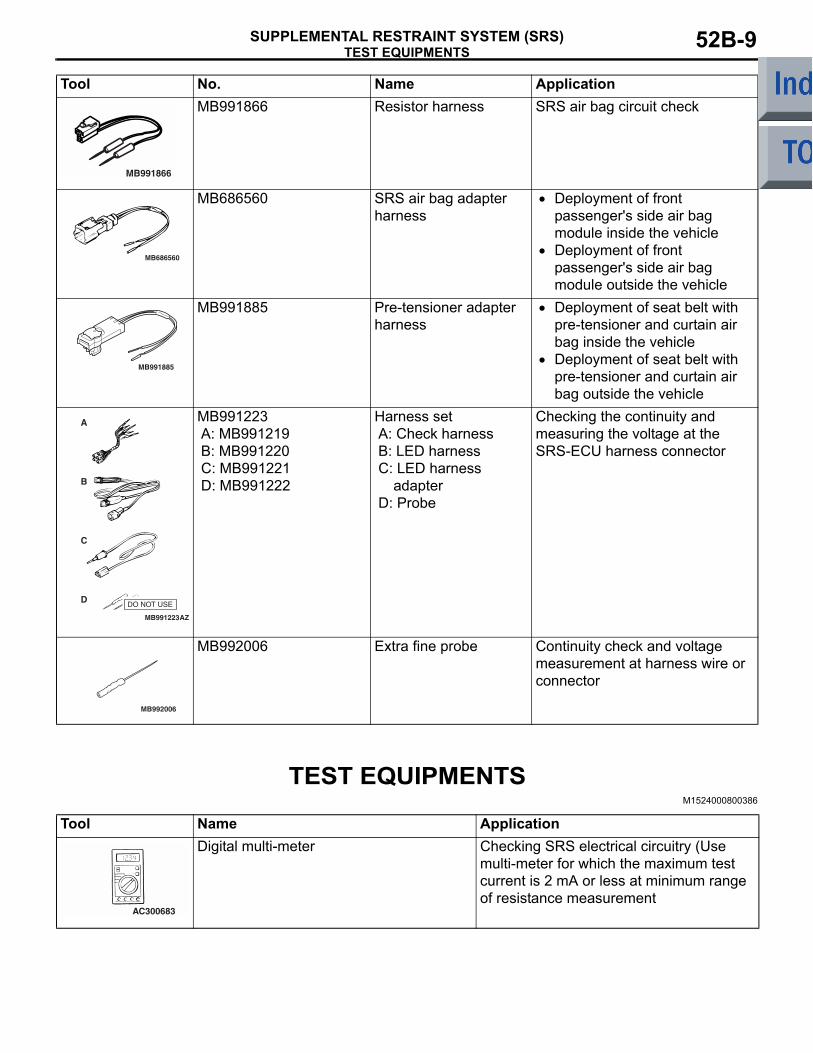
TEST EQUIPMENTSM1524000800386
MB991866 Resistor harness SRS air bag circuit check
MB686560 SRS air bag adapter harness
• Deployment of front passenger's side air bag module inside the vehicle
• Deployment of front passenger's side air bag module outside the vehicle
MB991885 Pre-tensioner adapter harness
• Deployment of seat belt with pre-tensioner and curtain air bag inside the vehicle
• Deployment of seat belt with pre-tensioner and curtain air bag outside the vehicle
MB991223A: MB991219B: MB991220C: MB991221D: MB991222
Harness setA: Check harnessB: LED harnessC: LED harness
adapterD: Probe
Checking the continuity and measuring the voltage at the SRS-ECU harness connector
MB992006 Extra fine probe Continuity check and voltage measurement at harness wire or connector
Tool No. Name Application
MB991866
MB686560
MB991885
MB991223
A
D
C
B
AZ
DO NOT USE
MB992006
Tool Name ApplicationDigital multi-meter Checking SRS electrical circuitry (Use
multi-meter for which the maximum test current is 2 mA or less at minimum range of resistance measurement
AC300683

TROUBLESHOOTINGSUPPLEMENTAL RESTRAINT SYSTEM (SRS)52B-10
TROUBLESHOOTINGDIAGNOSIS TROUBLESHOOTING FLOW
M1524003100568Refer to GROUP 00, Contents of Troubleshooting P.00-5.
DIAGNOSIS FUNCTIONM1524003200480
DIAGNOSIS CODES CHECKCAUTION
Turn off the ignition switch before connecting or disconnecting the M.U.T.-III.Connect the M.U.T.-III to the diagnosis connector (16-pin) under the instrument under cover, then check diagnosis codes (Refer to GROUP 00, Diag-nosis Function P.00-7).
ERASING DIAGNOSIS CODECAUTION
Turn off the ignition switch before connecting or disconnecting the M.U.T.-III.Connect the M.U.T.-III to the diagnosis connector and erase the diagnosis code (Refer to GROUP 00, Diagnosis Function P.00-7).
SRS WARNING LAMP CHECKM1524004300747
1. Check that the SRS warning lamp comes on when the ignition switch is turned ON.
2. Check that the SRS warning lamp illuminates for about 7 seconds and then goes out.
3. If this is not the cause, check the diagnosis codes.
AC510172
<VR-X>
<Except-VR-X>
SRS warning lamp
SRS warning lamp AC
TROUBLESHOOTINGSUPPLEMENTAL RESTRAINT SYSTEM (SRS) 52B-11
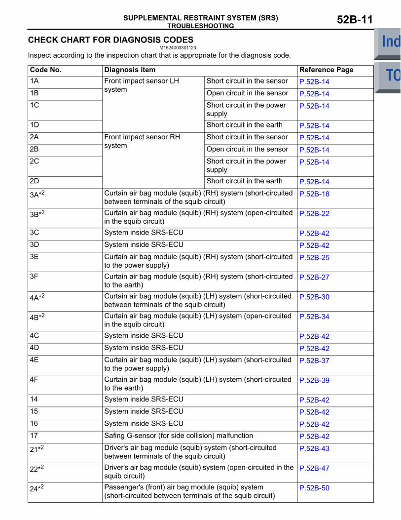
CHECK CHART FOR DIAGNOSIS CODESM1524003301123
Inspect according to the inspection chart that is appropriate for the diagnosis code.
Code No. Diagnosis item Reference Page1A Front impact sensor LH
systemShort circuit in the sensor P.52B-14
1B Open circuit in the sensor P.52B-141C Short circuit in the power
supplyP.52B-14
1D Short circuit in the earth P.52B-142A Front impact sensor RH
systemShort circuit in the sensor P.52B-14
2B Open circuit in the sensor P.52B-142C Short circuit in the power
supplyP.52B-14
2D Short circuit in the earth P.52B-14
3A*2 Curtain air bag module (squib) (RH) system (short-circuited between terminals of the squib circuit)
P.52B-18
3B*2 Curtain air bag module (squib) (RH) system (open-circuited in the squib circuit)
P.52B-22
3C System inside SRS-ECU P.52B-423D System inside SRS-ECU P.52B-423E Curtain air bag module (squib) (RH) system (short-circuited
to the power supply)P.52B-25
3F Curtain air bag module (squib) (RH) system (short-circuited to the earth)
P.52B-27
4A*2 Curtain air bag module (squib) (LH) system (short-circuited between terminals of the squib circuit)
P.52B-30
4B*2 Curtain air bag module (squib) (LH) system (open-circuited in the squib circuit)
P.52B-34
4C System inside SRS-ECU P.52B-424D System inside SRS-ECU P.52B-424E Curtain air bag module (squib) (LH) system (short-circuited
to the power supply)P.52B-37
4F Curtain air bag module (squib) (LH) system (short-circuited to the earth)
P.52B-39
14 System inside SRS-ECU P.52B-4215 System inside SRS-ECU P.52B-4216 System inside SRS-ECU P.52B-4217 Safing G-sensor (for side collision) malfunction P.52B-42
21*2 Driver's air bag module (squib) system (short-circuited between terminals of the squib circuit)
P.52B-43
22*2 Driver's air bag module (squib) system (open-circuited in the squib circuit)
P.52B-47
24*2 Passenger's (front) air bag module (squib) system (short-circuited between terminals of the squib circuit)
P.52B-50

TROUBLESHOOTINGSUPPLEMENTAL RESTRAINT SYSTEM (SRS)52B-12
25*2 Passenger's (front) air bag module (squib) system (open-circuited in the squib circuit)
P.52B-53
26*2 Driver's pre-tensioner (squib) system (short-circuited between terminals of the squib circuit)
P.52B-56
27*2 Driver's seat belt pre-tensioner (squib) system (open-circuited in the squib circuit)
P.52B-60
28*2 Passenger's (front) seat belt pre-tensioner (squib) system (short-circuit between terminals of the squib circuit)
P.52B-63
29*2 Passenger's (front) seat belt pre-tensioner (squib) system (open-circuited in the squib circuit)
P.52B-67
31 System inside SRS-ECU P.52B-4232 System inside SRS-ECU P.52B-42
34*1 SRS-ECU connector lock out of order P.52B-70
35 Ignition of the air bag completed P.52B-7139 Air bag deployed simultaneously P.52B-71
41*1 Power supply voltage (IG1 (A) voltage) drops abnormally. P.52B-71
42*1 Power supply voltage (IG1 (B) voltage) drops abnormally. P.52B-75
43*1 SRS warning lamp circuit open-circuited
Lamp does not illuminate P.52B-78Lamp does not switch off P.52B-81
44*1 SRS warning lamp circuit malfunction P.52B-83
45 System inside SRS-ECU P.52B-4251 System inside SRS-ECU P.52B-4252 System inside SRS-ECU P.52B-4254 System inside SRS-ECU P.52B-4255 System inside SRS-ECU P.52B-4256 System inside SRS-ECU P.52B-4257 System inside SRS-ECU P.52B-4258 System inside SRS-ECU P.52B-4259 System inside SRS-ECU P.52B-4261 Driver's air bag module (squib) system (short-circuited to the
power supply)P.52B-84
62 Driver's air bag module (squib) system (short-circuited to the earth)
P.52B-87
64 Passenger's (front) air bag module (squib) system (short-circuited to the power supply)
P.52B-90
65 Passenger's (front) air bag module (squib) system (short-circuited to the earth)
P.52B-92
66 Driver's seat belt pre-tensioner (squib) system (short-circuited to the power the supply)
P.52B-94
67 Driver's seat belt pre-tensioner (squib) system (short-circuited to the earth)
P.52B-97
Code No. Diagnosis item Reference Page

TROUBLESHOOTINGSUPPLEMENTAL RESTRAINT SYSTEM (SRS) 52B-13
NOTE: .
1. *1: If the vehicle condition returns to normal, the diagnosis code will be automatically erased, and the SRS warning lamp will return to normal.
2. *2: However, if no diagnosis code resets, the SRS warning lamp will be switched off (The diagnosis code will be retained).
3. If the vehicle has a discharged battery, it will store the diagnosis code 41 or 42. When these diagnosis codes are read, check the battery.
68 Passenger's (front) seat belt pre-tensioner (squib) system (short-circuited to the power supply)
P.52B-99
69 Passenger's (front) seat belt pre-tensioner (squib) system (short-circuited to the earth)
P.52B-102
71*2 Side-airbag module (squib) (RH) system (short-circuited between terminals of the squib circuit)
P.52B-105
72*2 Side-airbag module (squib) (RH) system (open-circuited in the squib circuit)
P.52B-108
73 System inside SRS-ECU P.52B-4274 System inside SRS-ECU P.52B-4275 Side-airbag module (squib) (RH) system (short-circuited to
the power supply)P.52B-110
76 Side-airbag module (squib) (RH) system (short-circuited to the earth)
P.52B-112
79 Side impact sensor (LH) (front) communication error P.52B-114
81*2 Side-airbag module (squib) (LH) system (short-circuited between terminals of the squib circuit)
P.52B-116
82*2 Side-airbag module (squib) (LH) system (open-circuited in the squib circuit)
P.52B-119
83 System inside SRS-ECU P.52B-4284 System inside SRS-ECU P.52B-4285 Side-airbag module (squib) (LH) system (short-circuited to
the power supply)P.52B-121
86 Side-airbag module (squib) (LH) system (short-circuited to the earth)
P.52B-123
89 Side impact sensor (RH) communication error P.52B-125
91*1 Side impact sensor (LH) voltage error P.52B-127
92 G-sensor of side impact sensor (LH) failure P.52B-12893 Side impact sensor (LH) communication impossible P.52B-114
94*1 Side impact sensor (RH) voltage error P.52B-129
95 G-sensor of side impact sensor (RH) failure P.52B-12896 Side impact sensor (RH) communication impossible P.52B-125
Code No. Diagnosis item Reference Page
TROUBLESHOOTINGSUPPLEMENTAL RESTRAINT SYSTEM (SRS)52B-14
DIAGNOSTIC TROUBLE CODE PROCEDURES
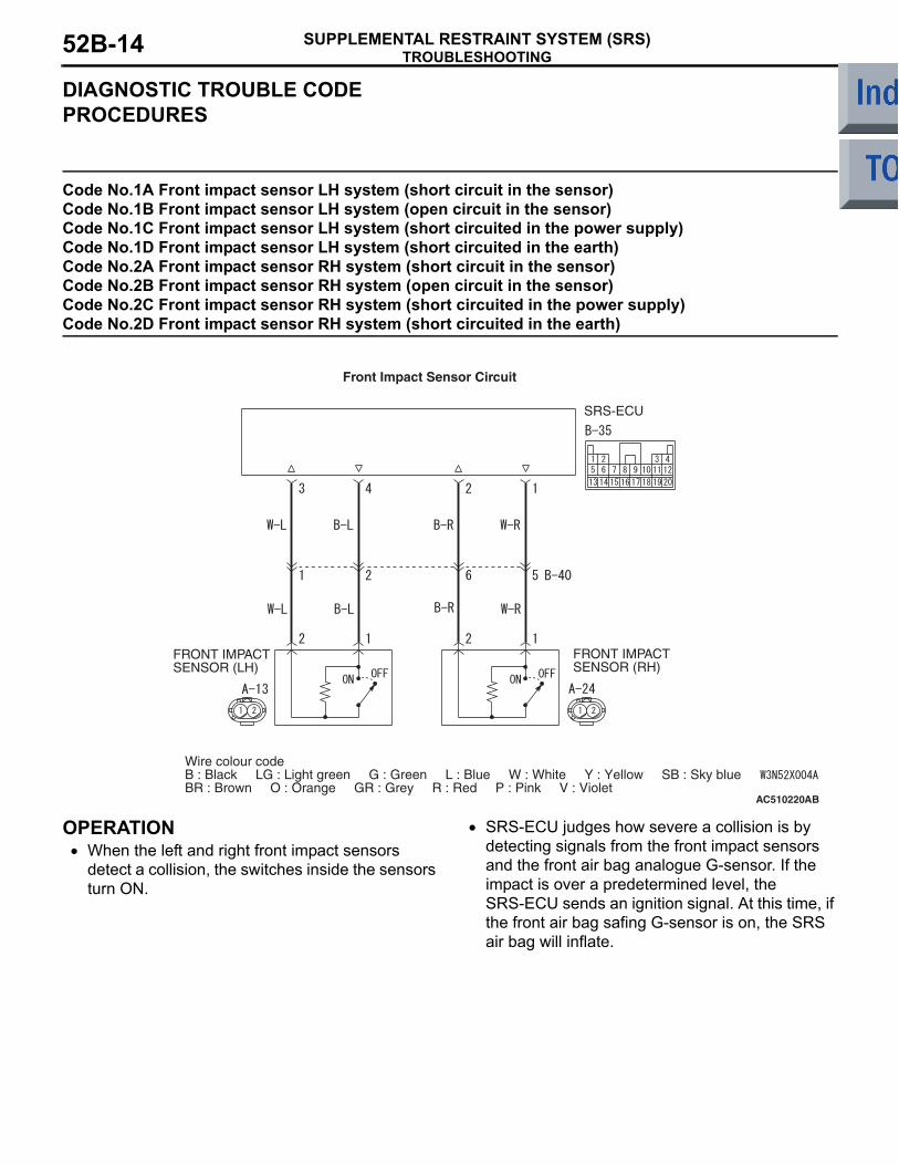
Code No.1A Front impact sensor LH system (short circuit in the sensor) Code No.1B Front impact sensor LH system (open circuit in the sensor) Code No.1C Front impact sensor LH system (short circuited in the power supply) Code No.1D Front impact sensor LH system (short circuited in the earth) Code No.2A Front impact sensor RH system (short circuit in the sensor) Code No.2B Front impact sensor RH system (open circuit in the sensor) Code No.2C Front impact sensor RH system (short circuited in the power supply) Code No.2D Front impact sensor RH system (short circuited in the earth)
OPERATION• When the left and right front impact sensors
detect a collision, the switches inside the sensors turn ON.
• SRS-ECU judges how severe a collision is by detecting signals from the front impact sensors and the front air bag analogue G-sensor. If the impact is over a predetermined level, the SRS-ECU sends an ignition signal. At this time, if the front air bag safing G-sensor is on, the SRS air bag will inflate.
AC510220
SRS-ECU
FRONT IMPACTSENSOR (RH)
FRONT IMPACTSENSOR (LH)
Wire colour codeB : Black LG : Light green G : Green L : Blue W : White Y : Yellow SB : Sky blueBR : Brown O : Orange GR : Grey R : Red P : Pink V : Violet
Front Impact Sensor Circuit
AB

TROUBLESHOOTINGSUPPLEMENTAL RESTRAINT SYSTEM (SRS) 52B-15
DIAGNOSIS CODE SET CONDITIONSThese diagnosis codes are set if these are abnormal resistance between the input terminals of the front impact sensors.The most likely causes for these codes to be set are shown in the table below:
PROBABLE CAUSES• Damaged harness wires and connectors• Front impact sensor failed• Malfunction of the SRS-ECU
DIAGNOSIS PROCEDURE
STEP 1. Check the front impact sensor. Refer to P.52B-142.
Q: Is the check result normal?YES : Go to Step 2.NO : Replace the front impact sensor (Refer to
P.52B-141).
STEP 2. Resistance measurement at the SRS-ECU connector B-35.(1) Disconnect the negative battery terminal.
(2) Disconnect SRS-ECU connector B-35.
CAUTION
Do not insert a test probe into the terminal from its front side directly as the connector contact pressure may be weakened.(3) Take the measurements below at harness-side
connector B-35.
Code No. Trouble causes1A • Left front impact sensor or its wiring shorted1B • Left front impact sensor or wiring open circuit1C • Short to the power supply in the left front impact sensor harness1D • Short to body earth in the left front impact sensor harness2A • Right front impact sensor or its wiring shorted2B • Right front impact sensor or wiring open circuit2C • Short to the power supply in the right front impact sensor harness2D • Short to body earth in the right front impact sensor harness
AC206285AF
B-35 (Y)
Connector: B-35
Harness side connector (rear view)
AC100338AC103684
13141516171819205 6 7 8 91011121 2 3 4
AC103683 AN
B-35 Harness side (rear view)
AC100338
13141516171819205 6 7 8 91011121 2 3 4
AC103684 AM
B-35 Harness side (rear view)

TROUBLESHOOTINGSUPPLEMENTAL RESTRAINT SYSTEM (SRS)52B-16
• Resistance between terminals 1 and 2 as well as 3 and 4.NG: 2 Ω or less (short circuit) or 2 MΩ or more (open circuit))
• Continuity between terminals 1, 2, 3, 4 and body earthOK: Open circuit
Q: Is the check result normal?YES : Go to Step 3.NO : Go to Step 4.
STEP 3. Voltage measurement at the SRS-ECU connector B-35.(1) Disconnect the negative battery terminal.
(2) Disconnect SRS-ECU connector B-35.(3) Connect the negative battery terminal.(4) Turn the ignition switch to the "ON" position.
CAUTION
Do not insert a test probe into the terminal from its front side directly as the connector contact pressure may be weakened.(5) Take the measurements below at harness-side
connector B-35.• Voltage between terminals 1, 2, 3, 4 and body
earthOK: 0V
Q: Is the check result normal?YES : Go to Step 5.NO : Go to Step 4.
AC103372
41 2 3
5 76 8
16151413
1211109
20191817
AK
B-35 Harness side (rear view)
AC206285AF
B-35 (Y)
Connector: B-35
Harness side connector (rear view)
41 2 3
5 76 8
16151413
1211109
20191817
AC210613
B-35 Harness side (rear view)
AD

TROUBLESHOOTINGSUPPLEMENTAL RESTRAINT SYSTEM (SRS) 52B-17
STEP 4. Check the wiring harness between the front impact sensor (RH) connector A-24 (terminals 1 and 2) and SRS-ECU connector B-35 (terminals 1 and 2) as well as between front impact sensor (LH) connector A-13 (terminals 1 and 2) and SRS-ECU connector B-35 (terminals 4 and 3).
NOTE:
Prior to the wiring harness inspection, check interme-diate connectors B-40, and repair if necessary.
• Check the front impact sensor output line for open or short circuit.
Q: Is the check result normal?YES : Go to Step 5.NO : Repair the wiring harness.
STEP 5. Check whether the diagnosis code is reset.Check again if the diagnosis code is set.
Q: Is diagnosis code 1A, 1B, 1C, 1D, 2A, 2B, 2C or 2D set?YES : Replace the SRS-ECU (Refer to
P.52B-143).NO : An intermittent malfunction is suspected
(Refer to GROUP 00, How to Cope with Intermittent Malfunction P.00-13).
AC313811
Connector: A-13
A-13 (Y)
AK
Harness side (front view)
2 1
AC313797
Connector: A-24
AG
A-24 (Y)
Harness side (front view)
2 1
AC206285AF
B-35 (Y)
Connector: B-35
Harness side connector (rear view)
AC313820 AM
Connector: B-40
26
15 9
37 8
410

TROUBLESHOOTINGSUPPLEMENTAL RESTRAINT SYSTEM (SRS)52B-18
Code No.3A: Curtain air bag module (squib) (RH) system (short-circuited between terminals of the squib circuit)
OPERATIONThe SRS-ECU judges how severe a collision is by detecting signals from the side impact sensors and the side-airbag safing G-sensor. If the impact is over a predetermined level, the SRS-ECU sends an igni-tion signal. At this time, if the side-airbag safing G-sensor is on, the curtain air bag module will deploy.
DIAGNOSIS CODE SET CONDITIONSThis diagnosis code is set if one curtain air bag mod-ule squib (RH) wire shorted to the other. However, if no diagnosis code resets, the SRS warning lamp will be switched off (diagnosis code will be retained).
PROBABLE CAUSES• Improper engaged connector or defective short
spring*• Short circuit between the curtain air bag module
(squib) (RH) circuit terminals• Damaged connector(s)• Malfunction of the SRS-ECU
NOTE: *: The squib circuit connectors integrate a "short" spring (which prevents the air bag from deploying unintentionally due to static electricity by shorting the positive wire to the earth wire in the squib circuit when the connectors are disconnected). Therefore, if connector B-34,C-09 or C-07 is dam-aged or improperly engaged, the short spring may not be released when the connector is connected.
AC510221
CONNECTORLOCKSWITCH
AIR BAGDRIVE CIRCUIT
SRS-ECU
MICROC OMPUTER
CONNECTORLOCKSWITCH
NOTECONNECTORCOUPLED: ONCONNECTORUNCOUPLED: OFF
Wire colour codeB : Black LG : Light greenG : Green L : Blue W : White Y : YellowSB : Sky blue BR : Brown O : Orange GR : Grey R : Red P : Pink V : Violet
CURTAIN AIR BAGMODULE (SQUIB)(RH)
Curtain Air Bag Module (Squib) (RH) Circuit
AB

TROUBLESHOOTINGSUPPLEMENTAL RESTRAINT SYSTEM (SRS) 52B-19
DIAGNOSIS PROCEDURE
STEP 1. M.U.T.-III diagnosis codeQ: Is diagnosis code 34 set?
YES : Go to Step 2.NO : Go to Step 3.
STEP 2. Connector lock check: SRS-ECU connector B-34 (M.U.T.-III diagnosis code).(1) Disconnect the negative battery terminal.
(2) Disconnect connectors B-34, and then reconnect them.
(3) Connector the negative battery terminal.(4) Erase the diagnosis code memory, and check the
diagnosis code.
Q: Is diagnosis code 3A set?YES : Go to Step 3.NO : The procedure is complete. It is assumed
that diagnosis code 3A set as connector B-34 was engaged improperly.
STEP 3. Connector lock check: SRS-ECU connector B-34, intermediate connector C-09 and curtain air bag module connector C-07 (M.U.T.-III diagnosis code). (1) Disconnect the negative battery terminal.
(2) Disconnect connectors B-34, C-09 and C-07, and then reconnect them. For connector C-07, use a flat-tipped screwdriver to pull out the locking button at the harness side connector, and then disconnect the connector.
(3) Connector the negative battery terminal.
AC206285AG
B-34 (Y)
Connector: B-34
Harness side connector (rear view)
3435363738394041422526272829303132332122 2324
AC206285AG
B-34 (Y)
Connector: B-34
Harness side connector (rear view)
3435363738394041422526272829303132332122 2324
AC401577
Connector: C-07
C-07 (B)
Harness sideconnector(front view)
AB
AC208384BJ
Locking button
C-07 Curtain air bag module connector
Flat-tippedscrewdriver
C-07 Harness side connector
AC208385
Connector: C-09
C-09 (R)
Quarter panel
AD
Harness side

TROUBLESHOOTINGSUPPLEMENTAL RESTRAINT SYSTEM (SRS)52B-20
(4) Erase the diagnosis code memory, and check the diagnosis code.
Q: Is diagnosis code 3A set?YES : Go to Step 4.NO : The procedure is complete. It is assumed
that diagnosis code 3A set as connector B-34, C-09 or C-07 was engaged improperly.
STEP 4. Check the diagnosis code by connecting a dummy resistor (M.U.T.-III diagnosis code).(1) Disconnect the negative battery terminal.
(2) Disconnect intermediate connector C-09 (connection between curtain air bag wiring harness and instrument panel wiring harness).
(3) Connect special tool dummy resistor (MB991865) to special tool resistor harness (MB991866).CAUTION
Do not insert a test probe into the terminal from its front side directly as the connector contact pressure may be weakened.(4) Connect special tool (MB991884) to the C-09
harness side connector by back probing.(5) Connect the negative battery terminal.(6) Erase diagnosis code memory, and then check
the diagnosis code.
Q: Is diagnosis code 3A set?YES : Go to Step 5.NO : Go to Step 6.
STEP 5. Resistance measurement at the SRS-ECU connector B-34.(1) Disconnect the negative battery terminal.
(2) Disconnect SRS-ECU connector B-34.DANGER
To prevents the air bag from deploying unin-tentionally, disconnect the curtain air bag harness connector C-09 to short the squib circuit.
CAUTION
Insert an insulator such as a cable tie to a depth of 4mm or more, otherwise the short spring will not be released.(3) Insert a cable tie [3 mm wide, 0.5 mm thick]
between terminals 29, 30 and the short spring to release the short spring.
AC208385
Connector: C-09
C-09 (R)
Quarter panel
AD
Harness side
AC006042CJ
MB991866(Resistor harness)
C-09 Intermediate harness sideconnector
C-09 Curtain air bagmodule (RH) side connector
MB991865 (Dummyresistor: 3 Ω)
AC206285AG
B-34 (Y)
Connector: B-34
Harness side connector (rear view)
3435363738394041422526272829303132332122 2324
AC208385
Connector: C-09
C-09 (R)
Quarter panel
AD
Harness side
AC208765
SectionA - A
B-34 Harness side connector(front view)
Cable tie
Short spring4 mm or more
Terminal
AG
A
A

TROUBLESHOOTINGSUPPLEMENTAL RESTRAINT SYSTEM (SRS) 52B-21
CAUTION
Do not insert a test probe into the terminal from its front side directly as the connector contact pressure may be weakened.(4) Resistance measurement between B-34 harness
side connector terminals 29 and 30.OK: Open circuit
Q: Is the check result normal?YES : Go to Step 7.NO : Repair the harness wire between SRS-ECU
connector B-34 (terminal No.29 and 30) and harness side connector C-09 (terminal No.1 and 2).
STEP 6. Resistance measurement at intermediate connector C-09.(1) Disconnect the negative battery terminal.
DANGER
To prevents the air bag from deploying unin-tentionally, disconnect the curtain air bag module connector C-07 to short the squib circuit.
(2) Disconnect curtain air bag module connector C-07. Use a flat-tipped screwdriver to pull out the locking button at the harness side connector, and then disconnect the connector.
(3) Disconnect intermediate connector C-09 (connection between curtain air bag wiring harness and instrument panel wiring harness). CAUTION
Insert an insulator such as a cable tie to a depth of 4mm or more, otherwise the short spring will not be released.(4) Insert a cable tie [3 mm wide, 0.5 mm thick]
between terminals 1, 2 and the short spring to release the short spring.CAUTION
Do not insert a test probe into the terminal from its front side directly as the connector contact pressure may be weakened.
AC006244
34 35 36 37 38 39 40 41 4225 26 27 28 29 30 31 32 3321 22 23 24
B-34Harness side connector (rear view)
AW
AC401577
Connector: C-07
C-07 (B)
Harness sideconnector(front view)
AB
AC208384BJ
Locking button
C-07 Curtain air bag module connector
Flat-tippedscrewdriver
C-07 Harness side connector
AC303537
4 mm or more
C-09 Curtain air bag module (RH) side connector (front view)
TerminalCable tieA
Shortspring Section
A - A
AJ
A
1 2
AC303538AG
C-09 Curtain air bag module (RH) side connector (rear view)

TROUBLESHOOTINGSUPPLEMENTAL RESTRAINT SYSTEM (SRS)52B-22
(5) Resistance measurement between C-09 curtain air bag module (RH) side connector terminals 1 and 2.
OK: Open circuitQ: Is the check result normal?
YES : Replace the curtain air bag module (Refer to P.52B-152).
NO : Repair the harness wire between curtain air bag module (RH) side connector C-09 (terminal No.1 and 2) and curtain air bag module connector C-07 (terminal No.1 and 2).
STEP 7. Check whether the diagnosis code is reset. Q: Is diagnosis code 3A set?
YES : Replace the SRS-ECU (Refer to P.52B-143).
NO : An intermittent malfunction is suspected (Refer to GROUP 00, How to Cope with Intermittent Malfunction P.00-13).
Code No.3B: Curtain air bag module (squib) (RH) system (open-circuited in the squib circuit)
OPERATIONThe SRS-ECU judges how severe a collision is by detecting signals from the side impact sensors and the side-airbag safing G-sensor. If the impact is over a predetermined level, the SRS-ECU sends an igni-tion signal. At this time, if the side-airbag safing G-sensor is on, the curtain air bag module will deploy.
DIAGNOSIS CODE SET CONDITIONSThis diagnosis code is set if curtain air bag module squib <RH> wire(s) are open-circuited. However, if no diagnosis code resets, the SRS warning lamp will be switched off (diagnosis code will be retained).
PROBABLE CAUSES• Improper connector contact• Open circuit in the curtain air bag module (squib)
(RH) circuit• Malfunction of the SRS-ECU
AC510221
CONNECTORLOCKSWITCH
AIR BAGDRIVE CIRCUIT
SRS-ECU
MICROC OMPUTER
CONNECTORLOCKSWITCH
NOTECONNECTORCOUPLED: ONCONNECTORUNCOUPLED: OFF
Wire colour codeB : Black LG : Light greenG : Green L : Blue W : White Y : YellowSB : Sky blue BR : Brown O : Orange GR : Grey R : Red P : Pink V : Violet
CURTAIN AIR BAGMODULE (SQUIB)(RH)
Curtain Air Bag Module (Squib) (RH) Circuit
AB

TROUBLESHOOTINGSUPPLEMENTAL RESTRAINT SYSTEM (SRS) 52B-23
DIAGNOSIS PROCEDURE
STEP 1. Check the diagnosis code by connecting a dummy resistor (M.U.T.-III diagnosis code).(1) Disconnect the negative battery terminal.
(2) Disconnect intermediate connector C-09 (connection between curtain air bag wiring harness and instrument panel wiring harness).
(3) Connect special tool dummy resistor (MB991865) to special tool resistor harness (MB991866).CAUTION
Do not insert a test probe into the terminal from its front side directly as the connector contact pressure may be weakened.(4) Connect special tool (MB991866) to the C-09
harness side connector by backprobing.(5) Connect the negative battery terminal.(6) Erase diagnosis code memory, and then check
the diagnosis code.
Q: Is diagnosis code 3B set?YES : Go to Step 2.NO : Go to Step 3.
STEP 2. Resistance measurement between SRS-ECU connector B-34 (terminal No.29 and 30) and harness side connector C-09 (terminal No.1 and 2).(1) Disconnect the negative battery terminal.
(2) Disconnect SRS-ECU connector B-34.
(3) Disconnect intermediate connector C-09 (connection between curtain air bag wiring harness and instrument panel wiring).CAUTION
Do not insert a test probe into the terminal from its front side directly as the connector contact pressure may be weakened.
(4) Resistance measurement between the following terminals.
• SRS-ECU connector B-34 terminal No.29 and harness side connector C-09 terminal No.1
• SRS-ECU connector B-34 terminal No.30 and harness side connector C-09 terminal No.2OK: Continuity (Less than 2 Ω)
AC208385
Connector: C-09
C-09 (R)
Quarter panel
AD
Harness side
AC006042CJ
MB991866(Resistor harness)
C-09 Intermediate harness sideconnector
C-09 Curtain air bagmodule (RH) side connector
MB991865 (Dummyresistor: 3 Ω)
AC206285AG
B-34 (Y)
Connector: B-34
Harness side connector (rear view)
3435363738394041422526272829303132332122 2324
AC208385
Connector: C-09
C-09 (R)
Quarter panel
AD
Harness side
34 35 36 37 38 39 40 41 4225 26 27 28 29 30 31 32 3321 22 23 24
1 2
AC208818
B-34Harness side connector(rear view)
C-09 Harness side connector
AC

TROUBLESHOOTINGSUPPLEMENTAL RESTRAINT SYSTEM (SRS)52B-24
Q: Are the check results normal?YES : Go to Step 4.NO : Repair the harness wire between SRS-ECU
connector B-34 (terminal No.29 and 30) and harness side connector C-09 (terminal No.1 and 2).
STEP 3. Resistance measurement between curtain air bag module (RH) side connector C-09 (terminal No.1 and 2) and the curtain air bag module C-07 (terminal No.1 and 2).
(1) Disconnect the negative battery terminal.
(2) Disconnect harness side connector C-09 and curtain air bag module connector C-07, and measure at the wiring harness side. For connector C-07, use a flat-tipped screwdriver to pull out the locking button at the harness side connector, and then disconnect the connector.
(3) Connect C-07 harness side connector to special tool resistor harness (MB991884).
CAUTION
Do not insert a test probe into the terminal from its front side directly as the connector contact pressure may be weakened.(4) Resistance measurement between the following
terminals. • Curtain air bag module (RH) side connector
C-09 terminal No.1 and special tool terminal No.2
• Curtain air bag module (RH) side connector C-09 terminal No.2 and special tool terminal No.1OK: Continuity (Less than 2 Ω)
Q: Are the check results normal?YES : Replace the curtain air bag module (Refer
to P.52B-152).NO : Repair the harness wire between curtain air
bag module (RH) side connector C-09 (terminal No.1 and 2) and curtain air bag module connector C-07 (terminal No.1 and 2).
STEP 4. Check whether the diagnosis code is reset.Q: Is diagnosis code No.3B set?
YES : Replace the SRS-ECU (Refer to P.52B-143).
NO : An intermittent malfunction is suspected (Refer to GROUP 00, How to Cope with Intermittent Malfunction P.00-13).
AC401577
Connectors: C-07, C-09
C-07 (B)Harness sideconnector(front view)
AE
C-09 (R)
C-07C-09
AC208384BJ
Locking button
C-07 Curtain air bag module connector
Flat-tippedscrewdriver
C-07 Harness side connector
AC201287BR
C-07 Harness sideconnector
MB991884
1 2
21
AC303565AE
Resister harness connector
C-09 Curtain air bag module (RH) side connector (rear view)

TROUBLESHOOTINGSUPPLEMENTAL RESTRAINT SYSTEM (SRS) 52B-25
Code No.3E: Curtain air bag module (squib) (RH) system (short-circuited to the power supply)
OPERATIONThe SRS-ECU judges how severe a collision is by detecting signals from the side impact sensors and the side-airbag safing G-sensor. If the impact is over a predetermined level, the SRS-ECU sends an igni-tion signal. At this time, if the side-airbag safing G-sensor is on, the curtain air bag module will deploy.
DIAGNOSIS CODE SET CONDITIONSThis diagnosis code is set if the curtain air bag mod-ule squib (RH) wire(s) are short-circuited to the power supply.
PROBABLE CAUSES• Damaged wiring harnesses or connectors• Short to the power supply in the curtain air bag
module (squib) (RH) harness• Malfunction of the SRS-ECU
DIAGNOSIS PROCEDURE
STEP 1. Check the diagnosis code by connecting a dummy resistor (M.U.T.-III diagnosis code).(1) Disconnect the negative battery terminal.
(2) Disconnect intermediate connector C-09 (connection between curtain air bag wiring harness and instrument panel wiring harness).
AC510221
CONNECTORLOCKSWITCH
AIR BAGDRIVE CIRCUIT
SRS-ECU
MICROC OMPUTER
CONNECTORLOCKSWITCH
NOTECONNECTORCOUPLED: ONCONNECTORUNCOUPLED: OFF
Wire colour codeB : Black LG : Light greenG : Green L : Blue W : White Y : YellowSB : Sky blue BR : Brown O : Orange GR : Grey R : Red P : Pink V : Violet
CURTAIN AIR BAGMODULE (SQUIB)(RH)
Curtain Air Bag Module (Squib) (RH) Circuit
AB
AC208385
Connector: C-09
C-09 (R)
Quarter panel
AD
Harness side

TROUBLESHOOTINGSUPPLEMENTAL RESTRAINT SYSTEM (SRS)52B-26
(3) Connect special tool dummy resistor (MB991865) to special tool resistor harness (MB991866).CAUTION
Do not insert a test probe into the terminal from its front side directly as the connector contact pressure may be weakened.(4) Connect special tool (MB991866) to the C-09
harness side connector by backprobing.(5) Connect the negative battery terminal.(6) Erase diagnosis code memory, and check the
diagnosis code.
Q: Is diagnosis code 3E set?YES : Go to Step 2.NO : Go to Step 3.
STEP 2. Voltage measurement at the SRS-ECU connector B-34.(1) Disconnect the negative battery terminal.
(2) Disconnect SRS-ECU connector B-34.(3) Connect the negative battery terminal.
(4) Turn the ignition switch to the "ON" position.CAUTION
Do not insert a test probe into the terminal from its front side directly as the connector contact pressure may be weakened.(5) Voltage measurement between B-34 harness
side connector terminals 29, 30 and body earth.OK: 0 V
Q: Is the check results normal?YES : Go to Step 4.NO : Repair the harness wire between SRS-ECU
connector B-34 (terminal No.29 and 30) and curtain air bag module (RH) side connector C-09 (terminal No.1 and 2).
STEP 3. Voltage measurement at the curtain air bag harness connector C-09.(1) Disconnect the negative battery terminal.
(2) Disconnect intermediate connector C-09 (connection between curtain air bag wiring harness and instrument panel wiring harness).
(3) Connect the negative battery terminal.
AC006042CJ
MB991866(Resistor harness)
C-09 Intermediate harness sideconnector
C-09 Curtain air bagmodule (RH) side connector
MB991865 (Dummyresistor: 3 Ω)
AC206285AG
B-34 (Y)
Connector: B-34
Harness side connector (rear view)
3435363738394041422526272829303132332122 2324
AC006259
34 35 36 37 38 39 40 41 4225 26 27 28 29 30 31 32 3321 22 23 24
AU
B-34 Harness side connector (rear view)
AC208385
Connector: C-09
C-09 (R)
Quarter panel
AD
Harness side

TROUBLESHOOTINGSUPPLEMENTAL RESTRAINT SYSTEM (SRS) 52B-27
(4) Turn the ignition switch to the "ON" position.CAUTION
Do not insert a test probe into the terminal from its front side directly as the connector contact pressure may be weakened.(5) Voltage measurement between C-09 curtain air
bag module (RH) side connector terminals 1, 2 and body earth.
OK: 0 V
Q: Is the check results normal?YES : Replace the curtain air bag module (Refer
to P.52B-152).NO : Repair the harness wire between curtain air
bag module (RH) connector C-09 (terminal No.1 and 2) and curtain air bag module connector C-07 (terminal No.1 and 2).
STEP 4. Check whether the diagnosis code is reset.Q: Is diagnosis code 3E set?
YES : Replace the SRS-ECU (Refer to P.52B-143).
NO : An intermittent malfunction is suspected (Refer to GROUP 00, How to Cope with Intermittent Malfunction P.00-13).
Code No.3F: Curtain air bag module (squib) (RH) system (short-circuited to the earth)
AC303709
21
AF
C-09 Curtain air bag module (RH) side connector (rear view)
AC510221
CONNECTORLOCKSWITCH
AIR BAGDRIVE CIRCUIT
SRS-ECU
MICROC OMPUTER
CONNECTORLOCKSWITCH
NOTECONNECTORCOUPLED: ONCONNECTORUNCOUPLED: OFF
Wire colour codeB : Black LG : Light greenG : Green L : Blue W : White Y : YellowSB : Sky blue BR : Brown O : Orange GR : Grey R : Red P : Pink V : Violet
CURTAIN AIR BAGMODULE (SQUIB)(RH)
Curtain Air Bag Module (Squib) (RH) Circuit
AB

TROUBLESHOOTINGSUPPLEMENTAL RESTRAINT SYSTEM (SRS)52B-28
OPERATIONThe SRS-ECU judges how severe a collision is by detecting signals from the side impact sensors and the side-airbag safing G-sensor. If the impact is over a predetermined level, the SRS-ECU sends an igni-tion signal. At this time, if the side-airbag safing G-sensor is on, the curtain air bag module will deploy.
DIAGNOSIS CODE SET CONDITIONSThis diagnosis code is set if the curtain air bag mod-ule squib (RH) wire(s) are short-circuited to the earth.
PROBABLE CAUSES• Damaged wiring harnesses or connectors• Short to the earth in the curtain air bag module
(squib) (RH) harness• Malfunction of the SRS-ECU
DIAGNOSIS PROCEDURE
STEP 1. Check the diagnosis code by connecting a dummy resistor (M.U.T.-III diagnosis code).(1) Disconnect the negative battery terminal.
(2) Disconnect intermediate connector C-09 (connection between curtain air bag wiring harness and instrument panel wiring harness).
(3) Connect special tool dummy resistor (MB991865) to special tool resistor harness (MB991866).
CAUTIONDo not insert a test probe into the terminal from its front side directly as the connector contact pressure may be weakened.(4) Connect special tool (MB991866) to the C-09
harness side connector by backprobing.(5) Connect the negative battery terminal.(6) Erase diagnosis code memory, and check the
diagnosis code.
Q: Is diagnosis code 3F set?YES : Go to Step 2.NO : Go to Step 3.
STEP 2. Resistance measurement at the SRS-ECU connector B-34.(1) Disconnect the negative battery terminal.
(2) Disconnect SRS-ECU connector B-34.
(3) Disconnect intermediate connector C-09 (connection between curtain air bag wiring harness and instrument panel wiring harness).
AC208385
Connector: C-09
C-09 (R)
Quarter panel
AD
Harness side
AC006042CJ
MB991866(Resistor harness)
C-09 Intermediate harness sideconnector
C-09 Curtain air bagmodule (RH) side connector
MB991865 (Dummyresistor: 3 Ω)
AC206285AG
B-34 (Y)
Connector: B-34
Harness side connector (rear view)
3435363738394041422526272829303132332122 2324
AC208385
Connector: C-09
C-09 (R)
Quarter panel
AD
Harness side

TROUBLESHOOTINGSUPPLEMENTAL RESTRAINT SYSTEM (SRS) 52B-29
CAUTION
Do not insert a test probe into the terminal from its front side directly as the connector contact pressure may be weakened.(4) Resistance measurement between B-34 harness
side connector terminals 29, 30 and body earth.OK: Open circuit
Q: Is the check result normal?YES : Go to Step 4.NO : Repair the harness wire between SRS-ECU
connector B-34 (terminal No.29 and 30) and harness side connector C-09 (terminal No.1 and 2).
STEP 3. Resistance measurement at the curtain air bag harness connector C-09.(1) Disconnect the negative battery terminal.
(2) Disconnect intermediate connector C-09 (connection between curtain air bag wiring harness and instrument panel wiring harness).
(3) Disconnect curtain air bag harness connector C-07. Use a flat-tipped screwdriver to pull out the locking button at the harness side connector, and then disconnect the connector.CAUTION
Do not insert a test probe into the terminal from its front side directly as the connector contact pressure may be weakened.(4) Resistance measurement between C-09 curtain
air bag module (RH) side connector terminals 1, 2 and body earth.
OK: Open circuitQ: Is the check result normal?
YES : Replace the curtain air bag module (Refer to P.52B-152).
NO : Repair the harness wire between curtain air bag module (LH) connector C-09 (terminal No.1 and 2) and curtain air bag module connector C-07 (terminal No.1 and 2).
AC006260
3435363738394041422526272829303132332122 2324
B-34 Harness side connector (rear view)
AL
AC208385
Connector: C-09
C-09 (R)
Quarter panel
AD
Harness side
AC401577
Connector: C-07
C-07 (B)
Harness sideconnector(front view)
AB
AC208384BJ
Locking button
C-07 Curtain air bag module connector
Flat-tippedscrewdriver
C-07 Harness side connector
AC303710
21
AE
C-09 Curtain air bag module side connector (rear view)

TROUBLESHOOTINGSUPPLEMENTAL RESTRAINT SYSTEM (SRS)52B-30
STEP 4. Check whether the diagnosis code is reset.Q: Is diagnosis code 3F set?
YES : Replace the SRS-ECU (Refer to P.52B-143).
NO : An intermittent malfunction is suspected (Refer to GROUP 00, How to Cope with Intermittent Malfunction P.00-13).
Code No.4A: Curtain air bag module (squib) (LH) system (short-circuited between terminals of the squib circuit)
OPERATIONThe SRS-ECU judges how severe a collision is by detecting signals from the side impact sensors and the side-airbag safing G-sensor. If the impact is over a predetermined level, the SRS-ECU sends an igni-tion signal. At this time, if the side-airbag safing G-sensor is on, the curtain air bag module will deploy.
DIAGNOSIS CODE SET CONDITIONSThis diagnosis code is set if one curtain air bag mod-ule squib (LH) wire shorted to the other. However, if no diagnosis code resets, the SRS warning lamp will be switched off (diagnosis code will be retained).
PROBABLE CAUSES• Improper engaged connector or defective short
spring*• Short circuit between the curtain air bag module
(squib) (LH) circuit terminals
AC510222
CURTAIN AIR BAGMODULE (SQUIB)(LH)
AIR BAGDRIVE CIRCUIT
SRS-ECU
MICRO COMPUTER
Wire colour codeB : Black LG : Light green G : Green L : Blue W : White Y : Yellow SB : Sky blueBR : Brown O : Orange GR : Grey R : Red P : Pink V : Violet
CONNECTORLOCKSWITCH
CONNECTORLOCKSWITCH
NOTECONNECTORCOUPLED: ONCONNECTORUNCOUPLED: OFF
Curtain Air Bag Module (Squib) (LH) Circuit
AB

TROUBLESHOOTINGSUPPLEMENTAL RESTRAINT SYSTEM (SRS) 52B-31
• Damaged connector(s)• Malfunction of the SRS-ECU
NOTE: *: The squib circuit connectors integrate a "short" spring (which prevents the air bag from deploying unintentionally due to static electricity by shorting the positive wire to the earth wire in the squib circuit when the connectors are disconnected). Therefore, if connector B-34, C-10 or C-13 is dam-aged or improperly engaged, the short spring may not be released when the connector is connected.
DIAGNOSIS PROCEDURE
STEP 1. M.U.T.-III diagnosis codeQ: Is diagnosis code 34 set?
YES : Go to Step 2.NO : Go to Step 3.
STEP 2. Connector lock check: SRS-ECU connector B-34 (M.U.T.-III diagnosis code).(1) Disconnect the negative battery terminal.
(2) Disconnect connectors B-34, and then reconnect them.
(3) Connector the negative battery terminal.(4) Erase the diagnosis code memory, and check the
diagnosis code.
Q: Is diagnosis code 4A set?YES : Go to Step 3.NO : The procedure is complete. It is assumed
that diagnosis code 4A set as connector B-34 was engaged improperly.
STEP 3. Connector lock check: SRS-ECU connector B-34, intermediate connector C-13 and curtain air bag module connector C-10 (M.U.T.-III diagnosis code). (1) Disconnect the negative battery terminal.
(2) Disconnect connectors B-34, C-13 and C-10, and then reconnect them. For connector C-10, use a flat-tipped screwdriver to pull out the locking button at the harness side connector, and then disconnect the connector.
(3) Connector the negative battery terminal.
AC206285AG
B-34 (Y)
Connector: B-34
Harness side connector (rear view)
3435363738394041422526272829303132332122 2324
AC206285AG
B-34 (Y)
Connector: B-34
Harness side connector (rear view)
3435363738394041422526272829303132332122 2324
AC401577
Connector: C-10
C-10 (B)
Harness sideconnector(front view)
AC
AC208384BK
C-10Curtain air bagmodule connector
Flat-tipped screwdriver
Locking button
C-10Harness sideconnector
AC209027
Connector: C-13
C-13 (R)
Quarter panel
AC
Harness side

TROUBLESHOOTINGSUPPLEMENTAL RESTRAINT SYSTEM (SRS)52B-32
(4) Erase the diagnosis code memory, and check the diagnosis code.
Q: Is diagnosis code 4A set?YES : Go to Step 4.NO : The procedure is complete. It is assumed
that diagnosis code 4A set as connector B-34, C-13 or C-10 was engaged improperly.
STEP 4. Check the diagnosis code by connecting a dummy resistor (M.U.T.-III diagnosis code).(1) Disconnect the negative battery terminal.
(2) Disconnect intermediate connector C-10 (connection between curtain air bag wring harness and instrument panel wring harness).
(3) Connect special tool dummy resistor (MB991865) to special tool resistor harness (MB991866).CAUTION
Do not insert a test probe into the terminal from its front side directly as the connector contact pressure may be weakened.(4) Connect special tool (MB991884) to the C-13
harness side connector by back probing.(5) Connect the negative battery terminal.(6) Erase diagnosis code memory, and then check
the diagnosis code.
Q: Is diagnosis code 4A set?YES : Go to Step 5.NO : Go to Step 6.
STEP 5. Resistance measurement at the SRS-ECU connector B-34.(1) Disconnect the negative battery terminal.
(2) Disconnect SRS-ECU connector B-34.DANGER
To prevents the air bag from deploying unin-tentionally, disconnect the curtain air bag harness connector C-13 to short the squib circuit.
CAUTION
Insert an insulator such as a cable tie to a depth of 4mm or more, otherwise the short spring will not be released.(3) Insert a cable tie [3 mm wide, 0.5 mm thick]
between terminals 27, 28 and the short spring to release the short spring.
AC401577
Connector: C-10
C-10 (B)
Harness sideconnector(front view)
AC
AC006042CK
MB991866(Resistor harness)
C-13 Intermediate harness sideconnector
MB991865 (Dummyresistor: 3 Ω)
C-13 Curtain air bagmodule (LH) side connector
AC206285AG
B-34 (Y)
Connector: B-34
Harness side connector (rear view)
3435363738394041422526272829303132332122 2324
AC209027
Connector: C-13
C-13 (R)
Quarter panel
AC
Harness side
AC208764
SectionA - A
B-34Harness side connector(front view)
Cable tie
Short spring4 mm or more
Terminal
AE
A
A

TROUBLESHOOTINGSUPPLEMENTAL RESTRAINT SYSTEM (SRS) 52B-33
CAUTION
Do not insert a test probe into the terminal from its front side directly as the connector contact pressure may be weakened.(4) Resistance measurement between B-34 harness
side connector terminals 27 and 28.OK: Open circuit
Q: Is the check result normal?YES : Go to Step 7.NO : Repair the harness wire between SRS-ECU
connector B-34 (terminal No.27 and 28) and harness side connector C-13 (terminal No.2 and 1).
STEP 6. Resistance measurement at intermediate connector C-13.(1) Disconnect the negative battery terminal.
DANGER
To prevents the air bag from deploying unin-tentionally, disconnect the curtain air bag module connector C-10 to short the squib circuit.
(2) Disconnect curtain air bag module connector C-10. Use a flat-tipped screwdriver to pull out the locking button at the harness side connector, and then disconnect the connector.
(3) Disconnect intermediate connector C-13 (connection between curtain air bag wiring harness and instrument panel wiring harness). CAUTION
Insert an insulator such as a cable tie to a depth of 4mm or more, otherwise the short spring will not be released.(4) Insert a cable tie [3 mm wide, 0.5 mm thick]
between terminals 1, 2 and the short spring to release the short spring.CAUTION
Do not insert a test probe into the terminal from its front side directly as the connector contact pressure may be weakened.
AC100326
34 35 36 37 38 39 40 41 4225 26 27 28 29 30 31 32 3321 22 23 24
AS
B-34 Harness side connector (rear view)
AC401577
Connector: C-10
C-10 (B)
Harness sideconnector(front view)
AC
AC208384BK
C-10Curtain air bagmodule connector
Flat-tipped screwdriver
Locking button
C-10Harness sideconnector
AC303537
4 mm or more
C-10 Curtain air bag module (LH) side connector (front view)
TerminalCable tieA
Shortspring Section
A - A
AK
A
1 2
AC303538AH
C-13 Curtain air bag module (LH) side connector (rear view)

TROUBLESHOOTINGSUPPLEMENTAL RESTRAINT SYSTEM (SRS)52B-34
(5) Resistance measurement between C-13 curtain air bag module (LH) side connector terminals 1 and 2.
OK: Open circuitQ: Is the check result normal?
YES : Replace the curtain air bag module (Refer to P.52B-152).
NO : Repair the harness wire between curtain air bag module (LH) side connector C-13 (terminal No.1 and 2) and curtain air bag module connector C-10 (terminal No.1 and 2).
STEP 7. Check whether the diagnosis code is reset. Q: Is diagnosis code 4A set?
YES : Replace the SRS-ECU (Refer to P.52B-143).
NO : An intermittent malfunction is suspected (Refer to GROUP 00, How to Cope with Intermittent Malfunction P.00-13).
Code No.4B: Curtain air bag module (squib) (LH) system (open-circuited in the squib circuit)
OPERATIONThe SRS-ECU judges how severe a collision is by detecting signals from the side impact sensors and the side-airbag safing G-sensor. If the impact is over a predetermined level, the SRS-ECU sends an igni-tion signal. At this time, if the side-airbag safing G-sensor is on, the curtain air bag module will deploy.
DIAGNOSIS CODE SET CONDITIONSThis diagnosis code is set if curtain air bag module squib <LH> wire(s) are open-circuited. However, if no diagnosis code resets, the SRS warning lamp will be switched off (diagnosis code will be retained).
AC510222
CURTAIN AIR BAGMODULE (SQUIB)(LH)
AIR BAGDRIVE CIRCUIT
SRS-ECU
MICRO COMPUTER
Wire colour codeB : Black LG : Light green G : Green L : Blue W : White Y : Yellow SB : Sky blueBR : Brown O : Orange GR : Grey R : Red P : Pink V : Violet
CONNECTORLOCKSWITCH
CONNECTORLOCKSWITCH
NOTECONNECTORCOUPLED: ONCONNECTORUNCOUPLED: OFF
Curtain Air Bag Module (Squib) (LH) Circuit
AB

TROUBLESHOOTINGSUPPLEMENTAL RESTRAINT SYSTEM (SRS) 52B-35
PROBABLE CAUSES• Improper connector contact• Open circuit in the curtain air bag module (squib)
(LH) circuit• Malfunction of the SRS-ECU
DIAGNOSIS PROCEDURE
STEP 1. Check the diagnosis code by connecting a dummy resistor (M.U.T.-III diagnosis code).(1) Disconnect the negative battery terminal.
(2) Disconnect intermediate connector C-13 (connection between curtain air bag wiring harness and instrument panel wiring harness).
(3) Connect special tool dummy resistor (MB991865) to special tool resistor harness (MB991866).CAUTION
Do not insert a test probe into the terminal from its front side directly as the connector contact pressure may be weakened.(4) Connect special tool (MB991866) to the C-13
harness side connector by backprobing.(5) Connect the negative battery terminal.(6) Erase diagnosis code memory, and then check
the diagnosis code.
Q: Is diagnosis code 4B set?YES : Go to Step 2.NO : Go to Step 3.
STEP 2. Resistance measurement between SRS-ECU connector B-34 (terminal No.27 and 28) and harness side connector C-13 (terminal No.2 and 1).(1) Disconnect the negative battery terminal.
(2) Disconnect SRS-ECU connector B-34.
(3) Disconnect intermediate connector C-13 (connection between curtain air bag wiring harness and instrument panel wiring harness).CAUTION
Do not insert a test probe into the terminal from its front side directly as the connector contact pressure may be weakened.
(4) Resistance measurement between the following terminals.
• SRS-ECU connector B-34 terminal No.27 and harness side connector C-13 terminal No.2
• SRS-ECU connector B-34 terminal No.28 and harness side connector C-13 terminal No.1OK: Continuity (Less than 2 Ω)
AC209027
Connector: C-13
C-13 (R)
Quarter panel
AC
Harness side
AC006042CK
MB991866(Resistor harness)
C-13 Intermediate harness sideconnector
MB991865 (Dummyresistor: 3 Ω)
C-13 Curtain air bagmodule (LH) side connector
AC206285AG
B-34 (Y)
Connector: B-34
Harness side connector (rear view)
3435363738394041422526272829303132332122 2324
AC209027
Connector: C-13
C-13 (R)
Quarter panel
AC
Harness side
AC208817
34 35 36 37 38 39 40 41 4225 26 27 28 29 30 31 32 3321 22 23 24
1 2
B-34 Harness side connector (rear view)
C-13 Harness side connector
AD
TROUBLESHOOTINGSUPPLEMENTAL RESTRAINT SYSTEM (SRS)52B-36
Q: Are the check results normal?YES : Go to Step 4.NO : Repair the harness wire between SRS-ECU
connector B-34 (terminal No.27 and 28) and harness side connector C-13 (terminal No.2 and 1).
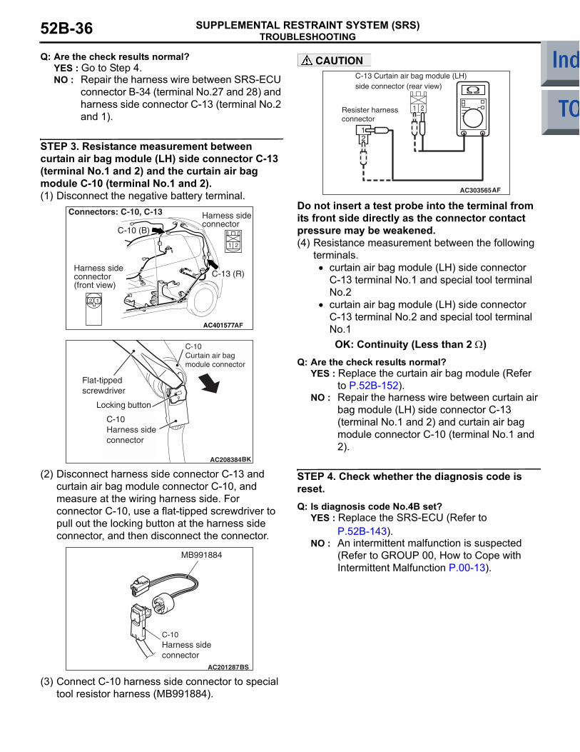
STEP 3. Resistance measurement between curtain air bag module (LH) side connector C-13 (terminal No.1 and 2) and the curtain air bag module C-10 (terminal No.1 and 2).(1) Disconnect the negative battery terminal.
(2) Disconnect harness side connector C-13 and curtain air bag module connector C-10, and measure at the wiring harness side. For connector C-10, use a flat-tipped screwdriver to pull out the locking button at the harness side connector, and then disconnect the connector.
(3) Connect C-10 harness side connector to special tool resistor harness (MB991884).
CAUTION
Do not insert a test probe into the terminal from its front side directly as the connector contact pressure may be weakened.(4) Resistance measurement between the following
terminals. • curtain air bag module (LH) side connector
C-13 terminal No.1 and special tool terminal No.2
• curtain air bag module (LH) side connector C-13 terminal No.2 and special tool terminal No.1OK: Continuity (Less than 2 Ω)
Q: Are the check results normal?YES : Replace the curtain air bag module (Refer
to P.52B-152).NO : Repair the harness wire between curtain air
bag module (LH) side connector C-13 (terminal No.1 and 2) and curtain air bag module connector C-10 (terminal No.1 and 2).
STEP 4. Check whether the diagnosis code is reset.Q: Is diagnosis code No.4B set?
YES : Replace the SRS-ECU (Refer to P.52B-143).
NO : An intermittent malfunction is suspected (Refer to GROUP 00, How to Cope with Intermittent Malfunction P.00-13).
AC401577
Connectors: C-10, C-13
C-10 (B)
Harness sideconnector(front view)
AF
C-13 (R)
Harness sideconnector
AC208384BK
C-10Curtain air bagmodule connector
Flat-tipped screwdriver
Locking button
C-10Harness sideconnector
AC201287BS
C-10 Harness sideconnector
MB991884
1 2
21
AC303565AF
Resister harness connector
C-13 Curtain air bag module (LH) side connector (rear view)

TROUBLESHOOTINGSUPPLEMENTAL RESTRAINT SYSTEM (SRS) 52B-37
Code No.4E: Curtain air bag module (squib) (LH) system (short-circuited to the power supply)
OPERATIONThe SRS-ECU judges how severe a collision is by detecting signals from the side impact sensors and the side-airbag safing G-sensor. If the impact is over a predetermined level, the SRS-ECU sends an igni-tion signal. At this time, if the side-airbag safing G-sensor is on, the curtain air bag module will deploy.
DIAGNOSIS CODE SET CONDITIONSThis diagnosis code is set if the curtain air bag mod-ule squib (LH) wire(s) are short-circuited to the power supply.
PROBABLE CAUSES• Damaged wiring harnesses or connectors• Short to the power supply in the curtain air bag
module (squib) (LH) harness• Malfunction of the SRS-ECU
DIAGNOSIS PROCEDURE
STEP 1. Check the diagnosis code by connecting a dummy resistor (M.U.T.-III diagnosis code).(1) Disconnect the negative battery terminal.
(2) Disconnect intermediate connector C-13 (connection between curtain air bag wiring harness and instrument panel wiring harness).
AC510222
CURTAIN AIR BAGMODULE (SQUIB)(LH)
AIR BAGDRIVE CIRCUIT
SRS-ECU
MICRO COMPUTER
Wire colour codeB : Black LG : Light green G : Green L : Blue W : White Y : Yellow SB : Sky blueBR : Brown O : Orange GR : Grey R : Red P : Pink V : Violet
CONNECTORLOCKSWITCH
CONNECTORLOCKSWITCH
NOTECONNECTORCOUPLED: ONCONNECTORUNCOUPLED: OFF
Curtain Air Bag Module (Squib) (LH) Circuit
AB
AC209027
Connector: C-13
C-13 (R)
Quarter panel
AC
Harness side

TROUBLESHOOTINGSUPPLEMENTAL RESTRAINT SYSTEM (SRS)52B-38
(3) Connect special tool dummy resistor (MB991865) to special tool resistor harness (MB991866).CAUTION
Do not insert a test probe into the terminal from its front side directly as the connector contact pressure may be weakened.(4) Connect special tool (MB991866) to the C-13
harness side connector by backprobing.(5) Connect the negative battery terminal.(6) Erase diagnosis code memory, and check the
diagnosis code.
Q: Is diagnosis code 4E set?YES : Go to Step 2.NO : Go to Step 3.
STEP 2. Voltage measurement at the SRS-ECU connector B-34.(1) Disconnect the negative battery terminal.
(2) Disconnect SRS-ECU connector B-34.(3) Connect the negative battery terminal.
(4) Turn the ignition switch to the "ON" position.CAUTION
Do not insert a test probe into the terminal from its front side directly as the connector contact pressure may be weakened.(5) Voltage measurement between B-34 harness
side connector terminals 27, 28 and body earth.OK: 0 V
Q: Is the check results normal?YES : Go to Step 4.NO : Repair the harness wire between SRS-ECU
connector B-34 (terminal No.27 and 28) and curtain air bag module (LH) side connector C-13 (terminal No.2 and 1).
STEP 3. Voltage measurement at the curtain air bag harness connector C-13.(1) Disconnect the negative battery terminal.
(2) Disconnect intermediate connector C-13 (connection between curtain air bag harness and floor harness).
(3) Connect the negative battery terminal.(4) Turn the ignition switch to the "ON" position.
AC006042CK
MB991866(Resistor harness)
C-13 Intermediate harness sideconnector
MB991865 (Dummyresistor: 3 Ω)
C-13 Curtain air bagmodule (LH) side connector
AC206285AG
B-34 (Y)
Connector: B-34
Harness side connector (rear view)
3435363738394041422526272829303132332122 2324
AC100341
34 35 36 37 38 39 40 41 4225 26 27 28 29 30 31 32 3321 22 23 24
B-34 Harness side connector (rear view)
AU
AC209027
Connector: C-13
C-13 (R)
Quarter panel
AC
Harness side

TROUBLESHOOTINGSUPPLEMENTAL RESTRAINT SYSTEM (SRS) 52B-39
CAUTION
Do not insert a test probe into the terminal from its front side directly as the connector contact pressure may be weakened.(5) Voltage measurement between C-13 curtain air
bag module (LH) side connector terminals 1, 2 and body earth.
OK: 0 V
Q: Is the check results normal?YES : Replace the curtain air bag module (Refer
to P.52B-152).NO : Repair the harness wire between curtain air
bag module (LH) connector C-13 (terminal No.1 and 2) and curtain air bag module connector C-10 (terminal No.1and 2).
STEP 4. Check whether the diagnosis code is reset.Q: Is diagnosis code 4E set?
YES : Replace the SRS-ECU (Refer to P.52B-143).
NO : An intermittent malfunction is suspected (Refer to GROUP 00, How to Cope with Intermittent Malfunction P.00-13).
Code No.4F: Curtain air bag module (squib) (LH) system (short-circuited to the earth)
AC303709
21
AG
C-13 Curtain air bag module (LH) side connector (rear view)
AC510222
CURTAIN AIR BAGMODULE (SQUIB)(LH)
AIR BAGDRIVE CIRCUIT
SRS-ECU
MICRO COMPUTER
Wire colour codeB : Black LG : Light green G : Green L : Blue W : White Y : Yellow SB : Sky blueBR : Brown O : Orange GR : Grey R : Red P : Pink V : Violet
CONNECTORLOCKSWITCH
CONNECTORLOCKSWITCH
NOTECONNECTORCOUPLED: ONCONNECTORUNCOUPLED: OFF
Curtain Air Bag Module (Squib) (LH) Circuit
AB

TROUBLESHOOTINGSUPPLEMENTAL RESTRAINT SYSTEM (SRS)52B-40
OPERATIONThe SRS-ECU judges how severe a collision is by detecting signals from the side impact sensors and the side-airbag safing G-sensor. If the impact is over a predetermined level, the SRS-ECU sends an igni-tion signal. At this time, if the side-airbag safing G-sensor is on, the curtain air bag module will deploy.
DIAGNOSIS CODE SET CONDITIONSThis diagnosis code is set if the curtain air bag mod-ule squib (LH) wire(s) are short-circuited to the earth.
PROBABLE CAUSES• Damaged wiring harnesses or connectors• Short to the earth in the curtain air bag module
(squib) (LH) harness• Malfunction of the SRS-ECU
DIAGNOSIS PROCEDURE
STEP 1. Check the diagnosis code by connecting a dummy resistor (M.U.T.-III diagnosis code).(1) Disconnect the negative battery terminal.
(2) Disconnect intermediate connector C-13 (connection between curtain air bag wiring harness and instrument panel wiring harness).
(3) Connect special tool dummy resistor (MB991865) to special tool resistor harness (MB991866).
CAUTIONDo not insert a test probe into the terminal from its front side directly as the connector contact pressure may be weakened.(4) Connect special tool (MB991866) to the C-13
harness side connector by backprobing.(5) Connect the negative battery terminal.(6) Erase diagnosis code memory, and check the
diagnosis code.
Q: Is diagnosis code 4F set?YES : Go to Step 2.NO : Go to Step 3.
STEP 2. Resistance measurement at the SRS-ECU connector B-34.(1) Disconnect the negative battery terminal.
(2) Disconnect SRS-ECU connector B-34.
(3) Disconnect intermediate connector C-13 (connection between curtain air bag wiring harness and instrument panel wiring harness).
AC209027
Connector: C-13
C-13 (R)
Quarter panel
AC
Harness side
AC006042CK
MB991866(Resistor harness)
C-13 Intermediate harness sideconnector
MB991865 (Dummyresistor: 3 Ω)
C-13 Curtain air bagmodule (LH) side connector
AC206285AG
B-34 (Y)
Connector: B-34
Harness side connector (rear view)
3435363738394041422526272829303132332122 2324
AC209027
Connector: C-13
C-13 (R)
Quarter panel
AC
Harness side

TROUBLESHOOTINGSUPPLEMENTAL RESTRAINT SYSTEM (SRS) 52B-41
CAUTION
Do not insert a test probe into the terminal from its front side directly as the connector contact pressure may be weakened.(4) Resistance measurement between B-34 harness
side connector terminals 27, 28 and body earth.OK: Open circuit
Q: Is the check result normal?YES : Go to Step 4.NO : Repair the harness wire between SRS-ECU
connector B-34 (terminal No.27 and 28) and harness side connector C-13 (terminal No.2 and 1).
STEP 3. Resistance measurement at the curtain air bag harness connector C-13.(1) Disconnect the negative battery terminal.
(2) Disconnect intermediate connector C-13 (connection between curtain air bag wiring harness and instrument panel wiring harness).
(3) Disconnect curtain air bag harness connector C-10. Use a flat-tipped screwdriver to pull out the locking button at the harness side connector, and then disconnect the connector.CAUTION
Do not insert a test probe into the terminal from its front side directly as the connector contact pressure may be weakened.(4) Resistance measurement between C-13 curtain
air bag module (LH) side connector terminals 1, 2 and body earth.
OK: Open circuitQ: Is the check result normal?
YES : Replace the curtain air bag module (Refer to P.52B-152).
NO : Repair the harness wire between curtain air bag module (LH) connector C-13 (terminal No.1 and 2) and curtain air bag module connector C-10 (terminal No.1 and 2).
AC100343
3435363738394041422526272829303132332122 2324
B-34 Harness side connector (rear view)
AL
AC209027
Connector: C-13
C-13 (R)
Quarter panel
AC
Harness side
AC401577
Connector: C-10
C-10 (B)
Harness sideconnector(front view)
AC
AC208384BK
C-10Curtain air bagmodule connector
Flat-tipped screwdriver
Locking button
C-10Harness sideconnector
AC303710
21
AF
C-13 Curtain air bag module side connector (rear view)

TROUBLESHOOTINGSUPPLEMENTAL RESTRAINT SYSTEM (SRS)52B-42
STEP 4. Check whether the diagnosis code is reset.Q: Is diagnosis code 4F set?
YES : Replace the SRS-ECU (Refer to P.52B-143).
NO : An intermittent malfunction is suspected (Refer to GROUP 00, How to Cope with Intermittent Malfunction P.00-13).
Code No.3C, 3D, 4C, 4D, 14, 15, 16, 17, 31, 32, 45, 51, 52, 54, 55, 56, 57, 58, 59, 73, 74, 83, 84 system inside SRS-ECU
DIAGNOSIS CODE SET CONDITIONSThese diagnosis codes are set when a fault is detected in the SRS-ECU. The most likely causes for this code to be set are shown in the table below:Code No. Part/Circuit integral to
SRS-ECUTrouble causes
3C Curtain air bag module (squib) (RH) (squib ignition drive circuit)
• Short circuit in the squib ignition drive circuit3D • Open circuit in the squib ignition drive circuit4C Curtain air bag module (squib)
(LH) (squib ignition drive circuit)• Short circuit in the squib ignition drive circuit
4D • Open circuit in the squib ignition drive circuit14 Analogue G-sensor • When the analogue G-sensor is not operating
• When the characteristics of the analogue G-sensor are abnormal
• When the output from the analogue G-sensor is abnormal
15 Safing G-sensor (for frontal collision)
• Short circuit in the safing G-sensor16 • Open circuit in the safing G-sensor17 Safing G-sensor (for side
collision)• When the safing G-sensor is not operating• When the characteristics of the safing G-sensor are
abnormal• When the output from the safing G-sensor is abnormal
31 Capacitor circuit • Voltage at the capacitor terminal is higher than the specified value for five seconds or more
32 • Voltage at the capacitor terminal is lower than the specified value for five seconds or more (This is not detected if diagnosis code No.41 or 42 indicating battery positive voltage drop has been sent).
45 Non-volatile memory (EEPROM) and A/D converter
• When the non-volatile memory (EEPROM) and A/D converter system are abnormal
51 Driver's air bag module (squib ignition drive circuit)
• Short circuit in the squib ignition drive circuit52 • Open circuit in the squib ignition drive circuit54 Passenger's (front) air bag
module (squib ignition drive circuit)
• Short circuit in the squib ignition drive circuit55 • Open circuit in the squib ignition drive circuit

TROUBLESHOOTINGSUPPLEMENTAL RESTRAINT SYSTEM (SRS) 52B-43
PROBABLE CAUSE• Malfunction of the SRS-ECU
DIAGNOSISReplace the SRS-ECU (Refer to P.52B-143).
Code No.21: Driver's air bag module (squib) system (short-circuited between terminals of the squib circuit)
56 Drivers seat belt pre-tensioner (squib ignition drive circuit)
• Short circuit in the squib ignition drive circuit57 • Open circuit in the squib ignition drive circuit58 Passengers (front) seat belt
pre-tensioner (squib ignition drive circuit)
• Short circuit in the squib ignition drive circuit59 • Open circuit in the squib ignition drive circuit
73 Side-airbag module (RH) (squib ignition drive circuit)
• Short circuit in the squib ignition drive circuit74 • Open circuit in the squib ignition drive circuit83 Side-airbag module (LH) (squib
ignition drive circuit)• Short circuit in the squib ignition drive circuit
84 • Open circuit in the squib ignition drive circuit
Code No. Part/Circuit integral to SRS-ECU
Trouble causes
AC510223
Wire colour codeB : Black LG : Light green G : Green L : Blue W : White Y : Yellow SB : Sky blueBR : Brown O : Orange GR : Grey R : Red P : Pink V : Violet
AIR BAG MODULE(SQUIB)(DRIVER'S SIDE)
CONNECTORLOCK SWITCH
CONNECTORLOCK SWITCH
CLOCK SPRING
SRS-ECU
CONNECTORLOCK SWITCH
NOTE: CONNECTOR COUPLED: ON CONNECTOR UNCOUPLED: OFF
Driver's Air Bag Module (Squib) Circuit
AB
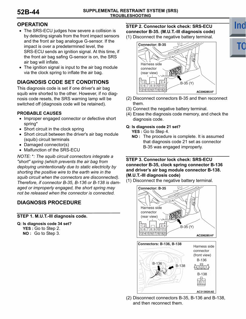
TROUBLESHOOTINGSUPPLEMENTAL RESTRAINT SYSTEM (SRS)52B-44
OPERATION• The SRS-ECU judges how severe a collision is
by detecting signals from the front impact sensors and the front air bag analogue G-sensor. If the impact is over a predetermined level, the SRS-ECU sends an ignition signal. At this time, if the front air bag safing G-sensor is on, the SRS air bag will inflate.
• The ignition signal is input to the air bag module via the clock spring to inflate the air bag.
DIAGNOSIS CODE SET CONDITIONSThis diagnosis code is set if one driver's air bag squib wire shorted to the other. However, if no diag-nosis code resets, the SRS warning lamp will be switched off (diagnosis code will be retained).
PROBABLE CAUSES• Improper engaged connector or defective short
spring*• Short circuit in the clock spring• Short circuit between the driver's air bag module
(squib) circuit terminals• Damaged connector(s)• Malfunction of the SRS-ECU
NOTE: *: The squib circuit connectors integrate a "short" spring (which prevents the air bag from deploying unintentionally due to static electricity by shorting the positive wire to the earth wire in the squib circuit when the connectors are disconnected). Therefore, if connector B-35, B-136 or B-138 is dam-aged or improperly engaged, the short spring may not be released when the connector is connected.
DIAGNOSIS PROCEDURE
STEP 1. M.U.T.-III diagnosis code.Q: Is diagnosis code 34 set?
YES : Go to Step 2.NO : Go to Step 3.
STEP 2. Connector lock check: SRS-ECU connector B-35. (M.U.T.-III diagnosis code)(1) Disconnect the negative battery terminal.
(2) Disconnect connectors B-35 and then reconnect them.
(3) Connect the negative battery terminal.(4) Erase the diagnosis code memory, and check the
diagnosis code.
Q: Is diagnosis code 21 set?YES : Go to Step 4.NO : The procedure is complete. It is assumed
that diagnosis code 21 set as connector B-35 was engaged improperly.
STEP 3. Connector lock check: SRS-ECU connector B-35, clock spring connector B-136 and drivers air bag module connector B-138. (M.U.T.-III diagnosis code)(1) Disconnect the negative battery terminal.
(2) Disconnect connectors B-35, B-136 and B-138, and then reconnect them.
AC206285AF
B-35 (Y)
Connector: B-35
Harness side connector (rear view)
AC206285AF
B-35 (Y)
Connector: B-35
Harness side connector (rear view)
AC313828AE
Connectors: B-136, B-138
B-138B-136
B-136
B-138
Harness side connector (front view)

TROUBLESHOOTINGSUPPLEMENTAL RESTRAINT SYSTEM (SRS) 52B-45
(3) Connect the negative battery terminal.(4) Erase the diagnosis code memory, and check the
diagnosis code.
Q: Is diagnosis code 21 set?YES : Go to Step 4.NO : The procedure is complete. It is assumed
that diagnosis code 21 set as connector B-35, B-136 or B-138 was engaged improperly.
STEP 4. Check the diagnosis code by connecting a dummy resistor. (M.U.T.-III diagnosis code)(1) Disconnect the negative battery terminal.
(2) By sliding the A section (in the figure) of air bag module connector B-138 in the arrow direction, disconnect the connector.
(3) Connect special tool dummy resistor (MB991865) to special tool resistor harness (MB991866).
CAUTIONDo not insert a test probe into the terminal from its front side directly as the connector contact pressure may be weakened.(4) Insert special tool (MB991866) into clock spring
side air bag module connector B-138 by backprobing.
(5) Connect the negative battery terminal.(6) Erase the diagnosis code memory, and check the
diagnosis code.
Q: Is diagnosis code 21 set?YES : Go to Step 5.NO : Replace the driver's air bag module (Refer
to P.52B-145).
STEP 5. Check the diagnosis code by connecting a dummy resistor. (M.U.T.-III diagnosis code)(1) Disconnect the negative battery terminal.
(2) Disconnect the clock spring connector B-136.(3) Connect special tool dummy resistor (MB991865)
to special tool resistor harness (MB991866).CAUTION
Do not insert a test probe into the terminal from its front side directly as the connector contact pressure may be weakened.(4) Insert special tool (MB991866) into clock spring
harness side connector B-136 (terminal No.3 and 4) by backprobing.
(5) Connect the negative battery terminal.(6) Erase the diagnosis code memory, and check the
diagnosis code.
AC105823
AC304700
AC305145AF
A
Steeringwheel
B-138 Air bag module connector
AC300945AG
MB991865(Dummy resistor : 3Ω)
MB991866(Resistor harness)
B-138 Air bag moduleconnector
AC313828 AF
Connectors: B-136
B-136
Harness side connector (rear view)
AC300949 AF
MB991865 (Dummyresistor : 3 Ω) MB991866
(Resistor harness)
B-136 Clock springconnector(Rear view)
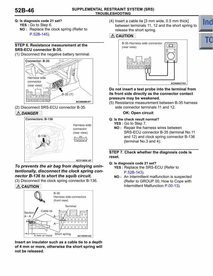
TROUBLESHOOTINGSUPPLEMENTAL RESTRAINT SYSTEM (SRS)52B-46
Q: Is diagnosis code 21 set?YES : Go to Step 6.NO : Replace the clock spring (Refer to
P.52B-145).
STEP 6. Resistance measurement at the SRS-ECU connector B-35.(1) Disconnect the negative battery terminal.
(2) Disconnect SRS-ECU connector B-35.DANGER
To prevents the air bag from deploying unin-tentionally, disconnect the clock spring con-nector B-136 to short the squib circuit.(3) Disconnect the clock spring connector B-136.
CAUTION
Insert an insulator such as a cable tie to a depth of 4 mm or more, otherwise the short spring will not be released.
(4) Insert a cable tie [3 mm wide, 0.5 mm thick] between terminals 11, 12 and the short spring to release the short spring.CAUTION
Do not insert a test probe into the terminal from its front side directly as the connector contact pressure may be weakened.(5) Resistance measurement between B-35 harness
side connector terminals 11 and 12.OK: Open circuit
Q: Is the check result normal? YES : Go to Step 7.NO : Repair the harness wires between
SRS-ECU connector B-35 (terminal No.11 and 12) and clock spring connector B-136 (terminal No.3 and 4).
STEP 7. Check whether the diagnosis code is reset.Q: Is diagnosis code 21 set?
YES : Replace the SRS-ECU (Refer to P.52B-143).
NO : An intermittent malfunction is suspected (Refer to GROUP 00, How to Cope with Intermittent Malfunction P.00-13).
AC206285AF
B-35 (Y)
Connector: B-35
Harness side connector (rear view)
AC313828 AF
Connectors: B-136
B-136
Harness side connector (rear view)
AC100391
SectionA - A
B-35 Harness side connectors(front view)
Cable tie
Short spring4 mm or more
Terminal
A
AZ
A
B-35 Harness side connector (rear view)
AS
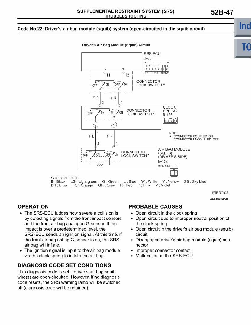
TROUBLESHOOTINGSUPPLEMENTAL RESTRAINT SYSTEM (SRS) 52B-47
Code No.22: Driver's air bag module (squib) system (open-circuited in the squib circuit)
OPERATION• The SRS-ECU judges how severe a collision is
by detecting signals from the front impact sensors and the front air bag analogue G-sensor. If the impact is over a predetermined level, the SRS-ECU sends an ignition signal. At this time, if the front air bag safing G-sensor is on, the SRS air bag will inflate.
• The ignition signal is input to the air bag module via the clock spring to inflate the air bag.
DIAGNOSIS CODE SET CONDITIONSThis diagnosis code is set if drivers air bag squib wire(s) are open-circuited. However, if no diagnosis code resets, the SRS warning lamp will be switched off (diagnosis code will be retained).
PROBABLE CAUSES• Open circuit in the clock spring• Open circuit due to improper neutral position of
the clock spring• Open circuit in the driver's air bag module (squib)
circuit• Disengaged driver's air bag module (squib) con-
nector• Improper connector contact• Malfunction of the SRS-ECU
AC510223
Wire colour codeB : Black LG : Light green G : Green L : Blue W : White Y : Yellow SB : Sky blueBR : Brown O : Orange GR : Grey R : Red P : Pink V : Violet
AIR BAG MODULE(SQUIB)(DRIVER'S SIDE)
CONNECTORLOCK SWITCH
CONNECTORLOCK SWITCH
CLOCK SPRING
SRS-ECU
CONNECTORLOCK SWITCH
NOTE: CONNECTOR COUPLED: ON CONNECTOR UNCOUPLED: OFF
Driver's Air Bag Module (Squib) Circuit
AB

TROUBLESHOOTINGSUPPLEMENTAL RESTRAINT SYSTEM (SRS)52B-48
DIAGNOSIS PROCEDURE
STEP 1. Check the diagnosis code by connecting a dummy resistor. (M.U.T.-III diagnosis code)(1) Disconnect the negative battery terminal.
(2) By sliding the A section (in the figure) of air bag module connector B-138 in the arrow direction, disconnect the connector.
(3) Connect special tool dummy resistor (MB991865) to special tool resistor harness (MB991866).CAUTION
Do not insert a test probe into the terminal from its front side directly as the connector contact pressure may be weakened.(4) Insert special tool (MB991866) into clock spring
side air bag module connector B-138 by backprobing.
(5) Connect the negative battery terminal.
(6) Erase the diagnosis code memory, and check the diagnosis code.
Q: Is diagnosis code 22 set?YES : Go to Step 2.NO : Replace the driver's air bag module (Refer
to P.52B-145).
STEP 2. Check the clock spring. (M.U.T.-III diagnosis code)(1) Disconnect the negative battery terminal.
(2) Disconnect the clock spring connector B-136.
(3) Connect special tool dummy resistor (MB991865) to special tool resistor harness (MB991866).CAUTION
Do not insert a test probe into the terminal from its front side directly as the connector contact pressure may be weakened.(4) Insert special tool (MB991866) into clock spring
harness side connector B-136 (terminal No.3 and 4) by backprobing.
(5) Connect the negative battery terminal.(6) Erase the diagnosis code memory, and check the
diagnosis code.
Q: Is diagnosis code 22 set?YES : Go to Step 3.NO : Replace the clock spring (Refer to
P.52B-145).
AC105823
AC304700
AC305145AF
A
Steeringwheel
B-138 Air bag module connector
AC300945AG
MB991865(Dummy resistor : 3Ω)
MB991866(Resistor harness)
B-138 Air bag moduleconnector
AC313828 AF
Connectors: B-136
B-136
Harness side connector (rear view)
AC300949 AF
MB991865 (Dummyresistor : 3 Ω) MB991866
(Resistor harness)
B-136 Clock springconnector(Rear view)

TROUBLESHOOTINGSUPPLEMENTAL RESTRAINT SYSTEM (SRS) 52B-49
STEP 3. Resistance measurement between the SRS-ECU connector B-35 (terminal No.11 and 12) and the clock spring connector B-136 (terminal No.3 and 4)(1) Disconnect the negative battery terminal.
(2) Disconnect SRS-ECU connector B-35 and clock spring connector B-136.
CAUTION
Do not insert a test probe into the terminal from its front side directly as the connector contact pressure may be weakened.(3) Resistance measurement between the following
terminals. • SRS-ECU connector B-35 terminal No.11 and
the clock spring connector B-136 terminal No.3
• SRS-ECU connector B-35 terminal No.12 and the clock spring connector B-136 terminal No.4OK: Continuity (Less than 2 Ω)
Q: Are the check results normal? YES : Go to Step 4. NO : Repair the harness wires between
SRS-ECU connector B-35 (terminal No.11 and 12) and clock spring connector B-136 (terminal No.3 and 4).
STEP 4. Check whether the diagnosis code is reset.Q: Is diagnosis code 22 set?
YES : Replace the SRS-ECU (Refer to P.52B-143).
NO : An intermittent malfunction is suspected (Refer to GROUP 00, How to Cope with Intermittent Malfunction P.00-13).
AC206285AF
B-35 (Y)
Connector: B-35
Harness side connector (rear view)
AC313828 AF
Connectors: B-136
B-136
Harness side connector (rear view)
1 2
AC105924
13 14 15 16 17 18 19 205 6 7 8 9 10 11 121 2 3 4
43
B-35Harness side connector (rear view)
B-136Harness side connector (rear view)
AH
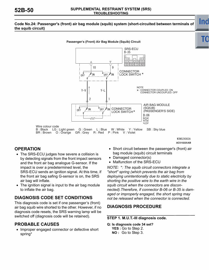
TROUBLESHOOTINGSUPPLEMENTAL RESTRAINT SYSTEM (SRS)52B-50
Code No.24: Passenger's (front) air bag module (squib) system (short-circuited between terminals of the squib circuit)
OPERATION• The SRS-ECU judges how severe a collision is
by detecting signals from the front impact sensors and the front air bag analogue G-sensor. If the impact is over a predetermined level, the SRS-ECU sends an ignition signal. At this time, if the front air bag safing G-sensor is on, the SRS air bag will inflate.
• The ignition signal is input to the air bag module to inflate the air bag.
DIAGNOSIS CODE SET CONDITIONSThis diagnosis code is set if one passengers (front) air bag squib wire shorted to the other. However, if no diagnosis code resets, the SRS warning lamp will be switched off (diagnosis code will be retained).
PROBABLE CAUSES• Improper engaged connector or defective short
spring*
• Short circuit between the passenger's (front) air bag module (squib) circuit terminals
• Damaged connector(s)• Malfunction of the SRS-ECU
NOTE: *: The squib circuit connectors integrate a "short" spring (which prevents the air bag from deploying unintentionally due to static electricity by shorting the positive wire to the earth wire in the squib circuit when the connectors are discon-nected).Therefore, if connector B-06 or B-35 is dam-aged or improperly engaged, the short spring may not be released when the connector is connected.
DIAGNOSIS PROCEDURE
STEP 1. M.U.T.-III diagnosis code.Q: Is diagnosis code 34 set?
YES : Go to Step 2.NO : Go to Step 3.
AC510225
CONNECTORLOCK SWITCH
AIR BAG MODULE(SQIUB)(PASSENGER'S SIDE)
SRS-ECU
CONNECTORLOCK SWITCH
Wire colour codeB : Black LG : Light green G : Green L : Blue W : White Y : Yellow SB : Sky blueBR : Brown O : Orange GR : Grey R : Red P : Pink V : Violet
NOTE: CONNECTOR COUPLED: ON CONNECTOR UNCOUPLED: OFF
Passenger's (Front) Air Bag Module (Squib) Circuit
AB

TROUBLESHOOTINGSUPPLEMENTAL RESTRAINT SYSTEM (SRS) 52B-51
STEP 2. Connector lock check: SRS-ECU connector B-35. (M.U.T.-III diagnosis code)(1) Disconnect the negative battery terminal.
(2) Disconnect the connectors B-35 and then reconnect them.
(3) Connect the negative battery terminal.(4) Erase the diagnosis code memory, and check the
diagnosis code.
Q: Is diagnosis code 24 set?YES : Go to Step 4.NO : The procedure is complete. It is assumed
that diagnosis code 24 set as connector B-35 was engaged improperly.
STEP 3. Connector lock check: SRS-ECU connector B-35 and passengers (front) air bag module connector B-06. (M.U.T.-III diagnosis code)(1) Disconnect the negative battery terminal.
(2) Disconnect connectors B-06 and B-35, and then reconnect them.
(3) Connect the negative battery terminal.(4) Erase the diagnosis code memory, and check the
diagnosis code.
Q: Is diagnosis code 24 set?YES : Go to Step 4.NO : The procedure is complete. It is assumed
that diagnosis code 24 set as connector B-06 or B-35 was engaged improperly.
STEP 4. Check the diagnosis code by connecting a dummy resistor. (M.U.T.-III diagnosis code)(1) Disconnect the negative battery terminal.
(2) Unclip passengers (front) air bag module connector B-06.
(3) Connect special tool dummy resistor (MB991865) to special tool resistor harness (MB991866).CAUTION
Do not insert a test probe into the terminal from its front side directly as the connector contact pressure may be weakened.(4) Disconnect the passenger's (front) air bag
module connector B-06 and insert special tool (MB991866) into the harness side connector by backprobing.
(5) Connect the negative battery terminal.(6) Erase the diagnosis code memory, and check the
diagnosis code.
Q: Is diagnosis code 24 set?YES : Go to Step 5.NO : Replace the passenger's (front) air bag
module (Refer to P.52B-145).
AC206285AF
B-35 (Y)
Connector: B-35
Harness side connector (rear view)
AC206285AF
B-35 (Y)
Connector: B-35
Harness side connector (rear view)
AC206286
Connector: B-06
2 1
Harness side connector (front view) B-06 (R)
AE
Glove box striker
AC206286
Connector: B-06
2 1
Harness side connector (front view) B-06 (R)
AE
Glove box striker
AC300956AN
MB991865(Dummy resistor: 3 )
MB991866 (Resistor harness)
B-06 Passenger's (front) air bag module connector
B-06 Harness side connector

TROUBLESHOOTINGSUPPLEMENTAL RESTRAINT SYSTEM (SRS)52B-52
STEP 5. Resistance measurement at SRS-ECU connector B-35.(1) Disconnect the negative battery terminal.
(2) Disconnect SRS-ECU connector B-35.
(3) Unclip passengers (front) air bag module connector B-06.DANGER
To prevents the air bag from deploying unin-tentionally, disconnect the passengers (front) air bag module connector B-06 to short the squib circuit.(4) Disconnect the passenger's (front) air bag
module connector B-06.CAUTION
Insert an insulator such as a cable tie to a depth of 4 mm or more, otherwise the short spring will not be released.
(5) Insert a cable tie [3 mm wide, 0.5 mm thick] between terminals 9, 10 and the short spring to release the short spring.CAUTION
Do not insert a test probe into the terminal from its front side directly as the connector contact pressure may be weakened.(6) Resistance measurement between B-35 harness
side connector terminals 9 and 10.OK: Open circuit
Q: Is the check result normal? YES : Go to Step 6.NO : Repair the harness wires between
SRS-ECU connector B-35 (terminal No.9 and 10) and passengers (front) air bag module connector B-06 (terminal No.1 and 2).
STEP 6. Check whether the diagnosis code is reset.Q: Is diagnosis code 24 set?
YES : Replace the SRS-ECU (Refer to P.52B-143).
NO : An intermittent malfunction is suspected (Refer to GROUP 00, How to Cope with Intermittent Malfunction P.00-13).
AC206285AF
B-35 (Y)
Connector: B-35
Harness side connector (rear view)
AC206286
Connector: B-06
2 1
Harness side connector (front view) B-06 (R)
AE
Glove box striker
AC006036
SectionA - A
B-35Harness side connectors(front view)
Cable tie
Short spring4 mm or more
Terminal
AX
A
A
13 14 15 16 17 18 19 205 6 7 8 9 10 11 121 2 3 4
AC006044
B-35 Harness side connector (rear view)
AS

TROUBLESHOOTINGSUPPLEMENTAL RESTRAINT SYSTEM (SRS) 52B-53
Code No.25: Passenger's (front) air bag module (squib) system (open-circuited in the squib circuit)
OPERATION• The SRS-ECU judges how severe a collision is
by detecting signals from the front impact sensors and the front air bag analogue G-sensor. If the impact is over a predetermined level, the SRS-ECU sends an ignition signal. At this time, if the front air bag safing G-sensor is on, the SRS air bag will inflate.
• The ignition signal is input to the air bag module to inflate the air bag.
DIAGNOSIS CODE SET CONDITIONSThis diagnosis code is set if passengers (front) air bag squib wire(s) are open-circuited. However, if no diagnosis code resets, the SRS warning lamp will be switched off (diagnosis code will be retained).
PROBABLE CAUSES• Open circuit in the passenger's (front) air bag
module (squib) circuit• Improper connector contact• Malfunction of the SRS-ECU
AC510225
CONNECTORLOCK SWITCH
AIR BAG MODULE(SQIUB)(PASSENGER'S SIDE)
SRS-ECU
CONNECTORLOCK SWITCH
Wire colour codeB : Black LG : Light green G : Green L : Blue W : White Y : Yellow SB : Sky blueBR : Brown O : Orange GR : Grey R : Red P : Pink V : Violet
NOTE: CONNECTOR COUPLED: ON CONNECTOR UNCOUPLED: OFF
Passenger's (Front) Air Bag Module (Squib) Circuit
AB

TROUBLESHOOTINGSUPPLEMENTAL RESTRAINT SYSTEM (SRS)52B-54
DIAGNOSIS PROCEDURE
STEP 1. Check the diagnosis code by connecting a dummy resistor. (M.U.T.-III diagnosis code)(1) Disconnect the negative battery terminal.
(2) Unclip passengers (front) air bag module connector B-06.
(3) Connect special tool dummy resistor (MB991865) to special tool resistor harness (MB991866).CAUTION
Do not insert a test probe into the terminal from its front side directly as the connector contact pressure may be weakened.(4) Disconnect the passenger's (front) air bag
module connector B-06, and insert special tool (MB991866) into the harness side connector by backprobing.
(5) Connect the negative battery terminal.(6) Erase the diagnosis code memory, and check the
diagnosis code.
Q: Is diagnosis code 25 set?YES : . Go to Step 2.NO : . Replace the passenger's (front) air bag
module (Refer to P.52B-145).
STEP 2. Resistance measurement between SRS-ECU connector B-35 (terminal No.9 and 10) and the passenger's (front) air bag module connector B-06 (terminal No.1 and 2).(1) Disconnect the negative battery terminal.
(2) Disconnect SRS-ECU connector B-35 and passenger's (front) air bag module connector B-06.
AC206286
Connector: B-06
2 1
Harness side connector (front view) B-06 (R)
AE
Glove box striker
AC300956AN
MB991865(Dummy resistor: 3 )
MB991866 (Resistor harness)
B-06 Passenger's (front) air bag module connector
B-06 Harness side connector
AC206285AF
B-35 (Y)
Connector: B-35
Harness side connector (rear view)
AC206286
Connector: B-06
2 1
Harness side connector (front view) B-06 (R)
AE
Glove box striker

TROUBLESHOOTINGSUPPLEMENTAL RESTRAINT SYSTEM (SRS) 52B-55
CAUTION
Do not insert a test probe into the terminal from its front side directly as the connector contact pressure may be weakened.(3) Resistance measurement between the following
terminals. • SRS-ECU connector B-35 terminal No.9 and
the passengers (front) air bag module con-nector B-06 terminal No.1
• SRS-ECU connector B-35 terminal No.10 and the passengers (front) air bag module con-nector B-06 terminal No.2OK: Continuity (Less than 2 Ω)
Q: Are the check results normal?YES : Go to Step 3.NO : Repair the harness wires between
SRS-ECU connector B-35 (terminal No.9 and 10) and passengers (front) air bag module connector B-06 (terminal No.1 and 2).
STEP 3. Check whether the diagnosis code is reset.Q: Is diagnosis code 25 set?
YES : Replace the SRS-ECU (Refer to P.52B-143).
NO : An intermittent malfunction is suspected (Refer to GROUP 00, How to Cope with Intermittent Malfunction P.00-13).
1 2
1 2 3 45 6 7 8 9 10 11 12
13 14 15 16 18 19 2017
AC100349
B-35 Harness side connector (rear view)
B-06 Harness sideconnector (rear view)
AN

TROUBLESHOOTINGSUPPLEMENTAL RESTRAINT SYSTEM (SRS)52B-56
Code No.26: Driver's pre-tensioner (squib) system (short-circuited between terminals of the squib circuit)
OPERATIONThe SRS-ECU judges how severe a collision is by detecting signals from the front impact sensors and the front air bag analogue G-sensor. If the impact is over a predetermined level, the SRS-ECU sends an ignition signal. At this time, if the front air bag safing G-sensor is on, the pre-tensioner will deploy.
DIAGNOSIS CODE SET CONDITIONSThis diagnosis code is set if one drivers pre-ten-sioner squib wire shorted to the other. However, if no diagnosis code resets, the SRS warning lamp will be switched off (diagnosis code will be retained).
PROBABLE CAUSES• Improper engaged connector or defective short
spring*• Short circuit between the driver's seat belt
pre-tensioner (squib) circuit terminals• Damaged connector(s)• Malfunction of the SRS-ECU
NOTE: *: The squib circuit connectors integrate a "short" spring (which prevents the air bag from deploying unintentionally due to static electricity by shorting the positive wire to the earth wire in the squib circuit when the connectors are disconnected). Therefore, if connector B-35 or C-28 is damaged or improperly engaged, the short spring may not be released when the connector is connected.
AC510230
Wire colour codeB : Black LG : Light green G : Green L : Blue W : White Y : Yellow SB : Sky blueBR : Brown O : Orange GR : Grey R : Red P : Pink V : Violet
SEAT BELTPRETENSIONER(RH)
SRS-ECU
CONNECTORLOCK SWITCH
CONNECTORLOCK SWITCH
NOTE: CONNECTOR COUPLED: ON CONNECTOR UNCOUPLED: OFF
Driver's Seat Belt Pre-Tensioner (Squib)
AB
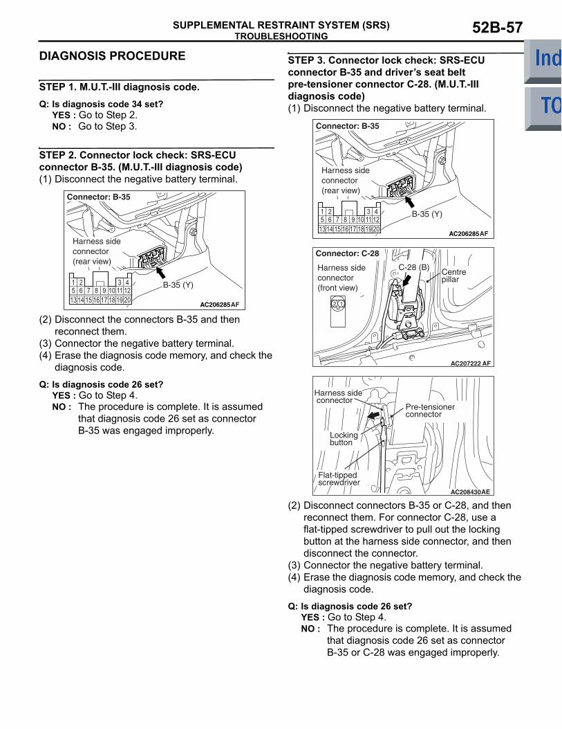
TROUBLESHOOTINGSUPPLEMENTAL RESTRAINT SYSTEM (SRS) 52B-57
DIAGNOSIS PROCEDURE
STEP 1. M.U.T.-III diagnosis code.Q: Is diagnosis code 34 set?
YES : Go to Step 2.NO : Go to Step 3.
STEP 2. Connector lock check: SRS-ECU connector B-35. (M.U.T.-III diagnosis code)(1) Disconnect the negative battery terminal.
(2) Disconnect the connectors B-35 and then reconnect them.
(3) Connector the negative battery terminal.(4) Erase the diagnosis code memory, and check the
diagnosis code.
Q: Is diagnosis code 26 set?YES : Go to Step 4.NO : The procedure is complete. It is assumed
that diagnosis code 26 set as connector B-35 was engaged improperly.
STEP 3. Connector lock check: SRS-ECU connector B-35 and drivers seat belt pre-tensioner connector C-28. (M.U.T.-III diagnosis code)(1) Disconnect the negative battery terminal.
(2) Disconnect connectors B-35 or C-28, and then reconnect them. For connector C-28, use a flat-tipped screwdriver to pull out the locking button at the harness side connector, and then disconnect the connector.
(3) Connector the negative battery terminal.(4) Erase the diagnosis code memory, and check the
diagnosis code.
Q: Is diagnosis code 26 set?YES : Go to Step 4.NO : The procedure is complete. It is assumed
that diagnosis code 26 set as connector B-35 or C-28 was engaged improperly.
AC206285AF
B-35 (Y)
Connector: B-35
Harness side connector (rear view)
AC206285AF
B-35 (Y)
Connector: B-35
Harness side connector (rear view)
AC207222 AF
Harness side connector (front view)
Connector: C-28
C-28 (B) Centrepillar
AC208430AE
Pre-tensionerconnector
Locking button
Harness side connector
Flat-tipped screwdriver
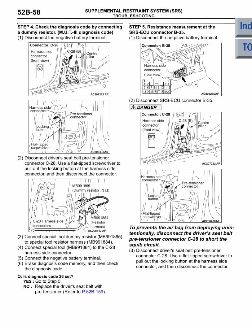
TROUBLESHOOTINGSUPPLEMENTAL RESTRAINT SYSTEM (SRS)52B-58
STEP 4. Check the diagnosis code by connecting a dummy resistor. (M.U.T.-III diagnosis code)(1) Disconnect the negative battery terminal.
(2) Disconnect driver's seat belt pre-tensioner connector C-28. Use a flat-tipped screwdriver to pull out the locking button at the harness side connector, and then disconnect the connector.
(3) Connect special tool dummy resistor (MB991865) to special tool resistor harness (MB991884).
(4) Connect special tool (MB991884) to the C-28 harness side connector.
(5) Connect the negative battery terminal.(6) Erase diagnosis code memory, and then check
the diagnosis code.
Q: Is diagnosis code 26 set?YES : Go to Step 5.NO : Replace the driver's seat belt with
pre-tensioner (Refer to P.52B-159).
STEP 5. Resistance measurement at the SRS-ECU connector B-35.(1) Disconnect the negative battery terminal.
(2) Disconnect SRS-ECU connector B-35.DANGER
To prevents the air bag from deploying unin-tentionally, disconnect the drivers seat belt pre-tensioner connector C-28 to short the squib circuit.(3) Disconnect driver's seat belt pre-tensioner
connector C-28. Use a flat-tipped screwdriver to pull out the locking button at the harness side connector, and then disconnect the connector.
AC207222 AF
Harness side connector (front view)
Connector: C-28
C-28 (B) Centrepillar
AC208430AE
Pre-tensionerconnector
Locking button
Harness side connector
Flat-tipped screwdriver
MB991865(Dummy resistor : 3 Ω)
C-28 Harness side connectors
MB991884(Resistorharness)
AF
AC206285AF
B-35 (Y)
Connector: B-35
Harness side connector (rear view)
AC207222 AF
Harness side connector (front view)
Connector: C-28
C-28 (B) Centrepillar
AC208430AE
Pre-tensionerconnector
Locking button
Harness side connector
Flat-tipped screwdriver

TROUBLESHOOTINGSUPPLEMENTAL RESTRAINT SYSTEM (SRS) 52B-59
CAUTION
Insert an insulator such as a cable tie to a depth of 4mm or more, otherwise the short spring will not be released.(4) Insert a cable tie [3 mm wide, 0.5 mm thick]
between terminals 7, 8 and the short spring to release the short spring.CAUTION
Do not insert a test probe into the terminal from its front side directly as the connector contact pressure may be weakened.
(5) Resistance measurement between B-35 harness side connector terminals 7 and 8.
OK: Open circuitQ: Is the check result normal?
YES : . Go to Step 6.NO : . Repair the harness wires between
SRS-ECU connector B-35 (terminal No.7 and 8) and drivers seat belt pre-tensioner connector C-28 (terminal No.1 and 2).
STEP 6. Check whether the diagnosis code is reset.Q: Is diagnosis code 26 set?
YES : Replace the SRS-ECU (Refer to P.52B-143).
NO : An intermittent malfunction is suspected (Refer to GROUP 00, How to Cope with Intermittent Malfunction P.00-13).
AC208509
SectionA - A
B-35 Harness side connector(front view)
Cable tie
Short spring
Terminal
AE4 mm or more
A
A
13 14 16 17 19 205 6 7 8 9 10 11 121 2 3 4
1815
AC208505
B-35Harness side connector (rear view)
AE

TROUBLESHOOTINGSUPPLEMENTAL RESTRAINT SYSTEM (SRS)52B-60
Code No.27: Driver's seat belt pre-tensioner (squib) system (open-circuited in the squib circuit)
OPERATIONThe SRS-ECU judges how severe a collision is by detecting signals from the front impact sensors and the front air bag analogue G-sensor. If the impact is over a predetermined level, the SRS-ECU sends an ignition signal. At this time, if the front air bag safing G-sensor is on, the pre-tensioner will deploy.
DIAGNOSIS CODE SET CONDITIONSThis diagnosis code is set if driver's seat belt pre-ten-sioner squib wire(s) are open-circuited. However, if no diagnosis code resets, the SRS warning lamp will be switched off (diagnosis code will be retained).
PROBABLE CAUSES• Improper connector contact• Open circuit in the driver's seat belt pre-tensioner
(squib) circuit• Malfunction of the SRS-ECU
AC510230
Wire colour codeB : Black LG : Light green G : Green L : Blue W : White Y : Yellow SB : Sky blueBR : Brown O : Orange GR : Grey R : Red P : Pink V : Violet
SEAT BELTPRETENSIONER(RH)
SRS-ECU
CONNECTORLOCK SWITCH
CONNECTORLOCK SWITCH
NOTE: CONNECTOR COUPLED: ON CONNECTOR UNCOUPLED: OFF
Driver's Seat Belt Pre-Tensioner (Squib)
AB

TROUBLESHOOTINGSUPPLEMENTAL RESTRAINT SYSTEM (SRS) 52B-61
DIAGNOSIS PROCEDURE
STEP 1. Check the diagnosis code by connecting a dummy resistor. (M.U.T.-III diagnosis code)(1) Disconnect the negative battery terminal.
(2) Disconnect driver's seat belt pre-tensioner connector C-28. Use a flat-tipped screwdriver to pull out the locking button at the harness side connector, and then disconnect the connector.
(3) Connect special tool dummy resistor (MB991865) to special tool resistor harness (MB991884).
(4) Connect special tool (MB991884) to the C-28 harness side connector.
(5) Connect the negative battery terminal.(6) Erase diagnosis code memory, and then check
the diagnosis code.
Q: Is diagnosis code 27 set?YES : . Go to Step 2.NO : . Replace the driver's seat belt with
pre-tensioner (Refer to P.52B-159).
STEP 2. Resistance measurement between SRS-ECU connector B-35 (terminal No.7 and 8) and the driver's seat belt pre-tensioner C-28 (terminal No.2 and 1).(1) Disconnect the negative battery terminal.
(2) Disconnect SRS-ECU connector B-35 and driver's seat belt pre-tensioner connector C-28, and measure at the wiring harness side. For connector C-28, use a flat-tipped screwdriver to pull out the locking button at the harness side connector, and then disconnect the connector.
AC207222 AF
Harness side connector (front view)
Connector: C-28
C-28 (B) Centrepillar
AC208430AE
Pre-tensionerconnector
Locking button
Harness side connector
Flat-tipped screwdriver
MB991865(Dummy resistor : 3 Ω)
C-28 Harness side connectors
MB991884(Resistorharness)
AF
AC206285AF
B-35 (Y)
Connector: B-35
Harness side connector (rear view)
AC207222 AF
Harness side connector (front view)
Connector: C-28
C-28 (B) Centrepillar
AC208430AE
Pre-tensionerconnector
Locking button
Harness side connector
Flat-tipped screwdriver
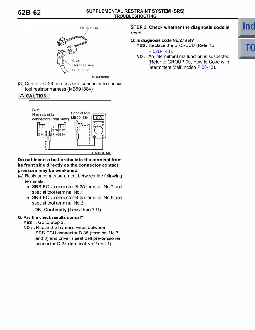
TROUBLESHOOTINGSUPPLEMENTAL RESTRAINT SYSTEM (SRS)52B-62
(3) Connect C-28 harness side connector to special tool resistor harness (MB991884).CAUTION
Do not insert a test probe into the terminal from its front side directly as the connector contact pressure may be weakened.(4) Resistance measurement between the following
terminals. • SRS-ECU connector B-35 terminal No.7 and
special tool terminal No.1• SRS-ECU connector B-35 terminal No.8 and
special tool terminal No.2OK: Continuity (Less than 2 Ω)
Q: Are the check results normal?YES : . Go to Step 3.NO : . Repair the harness wires between
SRS-ECU connector B-35 (terminal No.7 and 8) and drivers seat belt pre-tensioner connector C-28 (terminal No.2 and 1).
STEP 3. Check whether the diagnosis code is reset.Q: Is diagnosis code No.27 set?
YES : Replace the SRS-ECU (Refer to P.52B-143).
NO : An intermittent malfunction is suspected (Refer to GROUP 00, How to Cope with Intermittent Malfunction P.00-13).
AC201287BP
C-28Harness sideconnector
MB991884
13 14 15 16 17 19 205 6 7 8 9 10 11 121 2 3 4
18
21
AC208503AD
B-35 Harness sideconnectors (rear view)
Special toolMB991884

TROUBLESHOOTINGSUPPLEMENTAL RESTRAINT SYSTEM (SRS) 52B-63
Code No.28: Passenger's (front) seat belt pre-tensioner (squib) system (short-circuit between terminals of the squib circuit)
OPERATIONThe SRS-ECU judges how severe a collision is by detecting signals from the front impact sensors and the front air bag analogue G-sensor. If the impact is over a predetermined level, the SRS-ECU sends an ignition signal. At this time, if the front air bag safing G-sensor is on, the pre-tensioner will deploy.
DIAGNOSIS CODE SET CONDITIONSThis diagnosis code is set if one passengers (front) seat belt pre-tensioner squib wire shorted to the other. However, if no diagnosis code resets, the SRS warning lamp will be switched off (diagnosis code will be retained).
PROBABLE CAUSES• Improper engaged connector or defective short
spring*• Short circuit between the passenger's (front) seat
belt pre-tensioner (squib) circuit terminals• Damaged connector(s)• Malfunction of the SRS-ECU
NOTE: *: The squib circuit connectors integrate a "short" spring (which prevents the air bag from deploying unintentionally due to static electricity by shorting the positive wire to the earth wire in the squib circuit when the connectors are disconnected). Therefore, if connector B-35 or C-20 is damaged or improperly engaged, the short spring may not be released when the connector is connected.
AC510233
Wire colour codeB : Black LG : Light green G : Green L : Blue W : White Y : Yellow SB : Sky blueBR : Brown O : Orange GR : Grey R : Red P : Pink V : Violet
SEAT BELTPRETENSIONER(LH)
SRS-ECU
CONNECTORLOCK SWITCH
CONNECTORLOCK SWITCH
NOTE: CONNECTOR COUPLED: ON CONNECTOR UNCOUPLED: OFF
Passenger's (Front) Seat Belt Pre-tensioner (Squib)
AB

TROUBLESHOOTINGSUPPLEMENTAL RESTRAINT SYSTEM (SRS)52B-64
DIAGNOSIS PROCEDURE
STEP 1. M.U.T.-III diagnosis code.Q: Is diagnosis code 34 set?
YES : Go to Step 2.NO : Go to Step 3.
STEP 2. Connector lock check: SRS-ECU connector B-35. (M.U.T.-III diagnosis code)(1) Disconnect the negative battery terminal.
(2) Disconnect the connectors B-35 and then reconnect them.
(3) Connector the negative battery terminal.(4) Erase the diagnosis code memory, and check the
diagnosis code.
Q: Is diagnosis code 28 set?YES : Go to Step 4.NO : The procedure is complete. It is assumed
that diagnosis code 28 set as connector B-35 or C-20 was engaged improperly.
STEP 3. Connector lock check: SRS-ECU connector B-35 and passengers (front) seat belt pre-tensioner connector C-20. (M.U.T.-III diagnosis code)(1) Disconnect the negative battery terminal.
(2) Disconnect connectors B-35 or C-20, and then reconnect them. For connector C-20, use a flat-tipped screwdriver to pull out the locking button at the harness side connector, and then disconnect the connector.
(3) Connector the negative battery terminal.(4) Erase the diagnosis code memory, and check the
diagnosis code.
Q: Is diagnosis code 28 set?YES : Go to Step 4.NO : The procedure is complete. It is assumed
that diagnosis code 28 set as connector B-35 or C-20 was engaged improperly.
AC206285AF
B-35 (Y)
Connector: B-35
Harness side connector (rear view)
AC206285AF
B-35 (Y)
Connector: B-35
Harness side connector (rear view)
AC207223 AE
Harness side connector (front view)
Connector: C-20
C-20 (B) Centrepillar
AC208430AE
Pre-tensionerconnector
Locking button
Harness side connector
Flat-tipped screwdriver

TROUBLESHOOTINGSUPPLEMENTAL RESTRAINT SYSTEM (SRS) 52B-65
STEP 4. Check the diagnosis code by connecting a dummy resistor. (M.U.T.-III diagnosis code)(1) Disconnect the negative battery terminal.
(2) Disconnect passenger's (front) seat belt pre-tensioner connector C-20. Use a flat-tipped screwdriver to pull out the locking button at the harness side connector, and then disconnect the connector.
(3) Connect special tool dummy resistor (MB991865) to special tool resistor harness (MB991884).
(4) Connect special tool (MB991884) to the C-20 harness side connector.
(5) Connect the negative battery terminal.(6) Erase diagnosis code memory, and then check
the diagnosis code.
Q: Is diagnosis code 28 set?YES : Go to Step 5.NO : Replace the passenger's (front) seat belt
with pre-tensioner (Refer to P.52B-159). Then go to Step 6.
STEP 5. Resistance measurement at the SRS-ECU connector B-35.(1) Disconnect the negative battery terminal.
(2) Disconnect SRS-ECU connector B-35.DANGER
To prevents the air bag from deploying unin-tentionally, disconnect the passengers (front) seat belt pre-tensioner connector C-20 to short the squib circuit.(3) Disconnect passenger's (front) seat belt
pre-tensioner connector C-20. Use a flat-tipped screwdriver to pull out the locking button at the harness side connector, and then disconnect the connector.
AC207223 AE
Harness side connector (front view)
Connector: C-20
C-20 (B) Centrepillar
AC208430AE
Pre-tensionerconnector
Locking button
Harness side connector
Flat-tipped screwdriver
MB991865(Dummy resistor : 3 Ω)
C-20 Harness side connectors
MB991884(Resistorharness)
AG
AC206285AF
B-35 (Y)
Connector: B-35
Harness side connector (rear view)
AC207223 AE
Harness side connector (front view)
Connector: C-20
C-20 (B) Centrepillar
AC208430AE
Pre-tensionerconnector
Locking button
Harness side connector
Flat-tipped screwdriver

TROUBLESHOOTINGSUPPLEMENTAL RESTRAINT SYSTEM (SRS)52B-66
CAUTION
Insert an insulator such as a cable tie to a depth of 4 mm or more, otherwise the short spring will not be released.(4) Insert a cable tie [3 mm wide, 0.5 mm thick]
between terminals 5, 6 and the short spring to release the short spring.CAUTION
Do not insert a test probe into the terminal from its front side directly as the connector contact pressure may be weakened.(5) Resistance measurement between B-35 harness
side connector terminals 5 and 6.OK: Open circuit.
Q: Is the check result normal?YES : . Go to Step 6.NO : . Repair the harness wires between
SRS-ECU connector B-35 (terminal No.5 and 6) and passengers (front) seat belt pre-tensioner connector C-20 (terminal No.1 and 2).
STEP 6. Check whether the diagnosis code is reset. Q: Is diagnosis code 28 set?
YES : Replace the SRS-ECU (Refer to P.52B-143).
NO : An intermittent malfunction is suspected (Refer to GROUP 00, How to Cope with Intermittent Malfunction P.00-13).
AC208510
SectionA - A
B-35 Harness side connector(front view)
Cable tie
Short spring
Terminal
AE4 mm or more
A
A
13 14 16 17 19 205 6 7 8 9 10 11 121 2 3 4
1815
AC208507
B-35Harness side connector (rear view)
AE
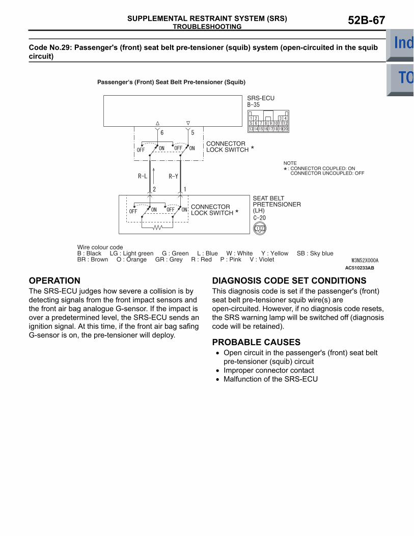
TROUBLESHOOTINGSUPPLEMENTAL RESTRAINT SYSTEM (SRS) 52B-67
Code No.29: Passenger's (front) seat belt pre-tensioner (squib) system (open-circuited in the squib circuit)
OPERATIONThe SRS-ECU judges how severe a collision is by detecting signals from the front impact sensors and the front air bag analogue G-sensor. If the impact is over a predetermined level, the SRS-ECU sends an ignition signal. At this time, if the front air bag safing G-sensor is on, the pre-tensioner will deploy.
DIAGNOSIS CODE SET CONDITIONSThis diagnosis code is set if the passenger's (front) seat belt pre-tensioner squib wire(s) are open-circuited. However, if no diagnosis code resets, the SRS warning lamp will be switched off (diagnosis code will be retained).
PROBABLE CAUSES• Open circuit in the passenger's (front) seat belt
pre-tensioner (squib) circuit• Improper connector contact• Malfunction of the SRS-ECU
AC510233
Wire colour codeB : Black LG : Light green G : Green L : Blue W : White Y : Yellow SB : Sky blueBR : Brown O : Orange GR : Grey R : Red P : Pink V : Violet
SEAT BELTPRETENSIONER(LH)
SRS-ECU
CONNECTORLOCK SWITCH
CONNECTORLOCK SWITCH
NOTE: CONNECTOR COUPLED: ON CONNECTOR UNCOUPLED: OFF
Passenger's (Front) Seat Belt Pre-tensioner (Squib)
AB

TROUBLESHOOTINGSUPPLEMENTAL RESTRAINT SYSTEM (SRS)52B-68
DIAGNOSIS PROCEDURE
STEP 1. Check the diagnosis code by connecting a dummy resistor. (M.U.T.-III diagnosis code)(1) Disconnect the negative battery terminal.
(2) Disconnect passenger's (front) seat belt pre-tensioner connector C-20. Use a flat-tipped screwdriver to pull out the locking button at the harness side connector, and then disconnect the connector.
(3) Connect special tool dummy resistor (MB991865) to special tool resistor harness (MB991884).
(4) Connect special tool (MB991884) to the C-20 harness side connector.
(5) Connect the negative battery terminal.(6) Erase diagnosis code memory, and then check
the diagnosis code.
Q: Is diagnosis code 29 set?YES : . Go to Step 2.NO : . Replace the passenger's (front) seat belt
with pre-tensioner (Refer to P.52B-159).
STEP 2. Resistance measurement between SRS-ECU connector B-35 (terminal No.5 and 6) and the passenger's (front) seat belt pre-tensioner connector C-20 (terminal No.1 and 2)(1) Disconnect the negative battery terminal.
(2) Disconnect SRS-ECU connector B-35 and passenger's (front) seat belt pre-tensioner connector C-20. For connector C-20, use a flat-tipped screwdriver to pull out the locking button at the harness side connector, and then disconnect the connector.
AC207223 AE
Harness side connector (front view)
Connector: C-20
C-20 (B) Centrepillar
AC208430AE
Pre-tensionerconnector
Locking button
Harness side connector
Flat-tipped screwdriver
MB991865(Dummy resistor : 3 Ω)
C-20 Harness side connectors
MB991884(Resistorharness)
AG
AC206285AF
B-35 (Y)
Connector: B-35
Harness side connector (rear view)
AC207223 AE
Harness side connector (front view)
Connector: C-20
C-20 (B) Centrepillar
AC208430AE
Pre-tensionerconnector
Locking button
Harness side connector
Flat-tipped screwdriver

TROUBLESHOOTINGSUPPLEMENTAL RESTRAINT SYSTEM (SRS) 52B-69
(3) Connect C-20 harness side connector to special tool resistor harness (MB991884).CAUTION
Do not insert a test probe into the terminal from its front side directly as the connector contact pressure may be weakened.
(4) Resistance measurement between the following terminals.
• SRS-ECU connector B-35 terminal No.5 and the special tool terminal No.2
• SRS-ECU connector B-35 terminal No.6 and the special tool terminal No.1OK: Continuity (Less than 2 Ω)
Q: Are the check results normal?YES : . Go to Step 3.NO : . Repair the harness wires between
SRS-ECU connector B-35 (terminal No.5 and 6) passengers (front) seat belt pre-tensioner connector C-20 (terminal No.1 and 2).
STEP 3.Check whether the diagnosis code is reset.Q: Is diagnosis code 29 set?
YES : Replace the SRS-ECU (Refer to P.52B-143).
NO : An intermittent malfunction is suspected (Refer to GROUP 00, How to Cope with Intermittent Malfunction P.00-13).
AC201287BQ
C-20 Harness sideconnector
MB991884
13 14 16 17 19 205 6 7 8 9 10 11 121 2 3 4
1815
21
AC208506AD
Resister harness connector
B-35 Harness side connector (rear view)
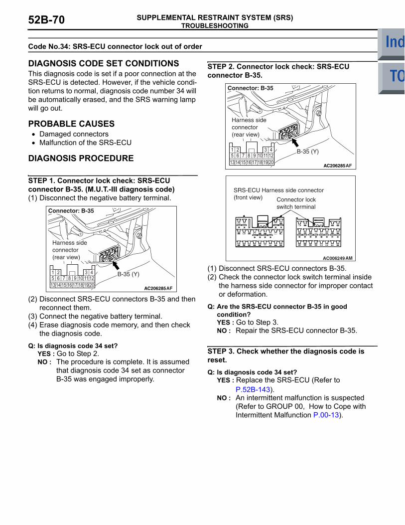
TROUBLESHOOTINGSUPPLEMENTAL RESTRAINT SYSTEM (SRS)52B-70
Code No.34: SRS-ECU connector lock out of order
DIAGNOSIS CODE SET CONDITIONSThis diagnosis code is set if a poor connection at the SRS-ECU is detected. However, if the vehicle condi-tion returns to normal, diagnosis code number 34 will be automatically erased, and the SRS warning lamp will go out.
PROBABLE CAUSES• Damaged connectors• Malfunction of the SRS-ECU
DIAGNOSIS PROCEDURE
STEP 1. Connector lock check: SRS-ECU connector B-35. (M.U.T.-III diagnosis code)(1) Disconnect the negative battery terminal.
(2) Disconnect SRS-ECU connectors B-35 and then reconnect them.
(3) Connect the negative battery terminal.(4) Erase diagnosis code memory, and then check
the diagnosis code.
Q: Is diagnosis code 34 set? YES : Go to Step 2.NO : The procedure is complete. It is assumed
that diagnosis code 34 set as connector B-35 was engaged improperly.
STEP 2. Connector lock check: SRS-ECU connector B-35.
(1) Disconnect SRS-ECU connectors B-35. (2) Check the connector lock switch terminal inside
the harness side connector for improper contact or deformation.
Q: Are the SRS-ECU connector B-35 in good condition? YES : Go to Step 3.NO : Repair the SRS-ECU connector B-35.
STEP 3. Check whether the diagnosis code is reset.Q: Is diagnosis code 34 set?
YES : Replace the SRS-ECU (Refer to P.52B-143).
NO : An intermittent malfunction is suspected (Refer to GROUP 00, How to Cope with Intermittent Malfunction P.00-13).
AC206285AF
B-35 (Y)
Connector: B-35
Harness side connector (rear view)
AC206285AF
B-35 (Y)
Connector: B-35
Harness side connector (rear view)
AC006249 AM
SRS-ECU Harness side connector (front view) Connector lock
switch terminal

TROUBLESHOOTINGSUPPLEMENTAL RESTRAINT SYSTEM (SRS) 52B-71
Code No.35: Ignition of the air bag completed
DIAGNOSIS CODE SET CONDITIONSThis diagnosis code is set after the air bag has deployed. If this diagnosis code is set before the air bag has deployed, the cause is probably a malfunc-tion inside the SRS-ECU.
PROBABLE CAUSEMalfunction of the SRS-ECU
DIAGNOSISReplace the SRS-ECU. (Refer to P.52B-143).
Code No.39 Airbags Deployed Simultaneously
DIAGNOSIS CODE SET CONDITIONSThis code is set when the airbags have deployed simultaneously. If this code is set before the airbags have deployed, an internal failure may have occurred in the SRS-ECU.
PROBABLE CAUSEMalfunction of the SRS-ECU
DIAGNOSISReplace the SRS-ECU (Refer to P.52B-143).
Code No.41: Power supply voltage (IG1 (A) voltage) drops abnormally.
AC510234
Wire colour codeB : Black LG : Light green G : Green L : Blue W : White Y : Yellow SB : Sky blueBR : Brown O : Orange GR : Grey R : Red P : Pink V : Violet
IGNITIONSWITCH (IG1)
SRS-ECU
IG1 Power Supply Circuit System
AB

TROUBLESHOOTINGSUPPLEMENTAL RESTRAINT SYSTEM (SRS)52B-72
OPERATION• The SRS-ECU is powered from the ignition
switch (IG1).• The SRS-ECU power is supplied from two cir-
cuits. Even if one circuit is shut off, the air bag can inflate.
DIAGNOSIS CODE SET CONDITIONSThis diagnosis code is set if the voltage between the IG1 terminals (fuse No.40 circuit) and earth is lower than a predetermined value for a continuous period of 5 second or more. However, if the system returns to normal condition, code number 41 will be erased automatically and the SRS warning lamp will go out.
PROBABLE CAUSES• Damaged wiring harnesses or connectors• Malfunction of the SRS-ECU
DIAGNOSIS PROCEDURE
STEP 1. Check junction block fuse number 40.
Q: Is the fuse burned out?YES : Go to Step 4.NO : Go to Step 2.
STEP 2. Voltage measurement at the SRS-ECU connector B-35.(1) Disconnect the negative battery terminal.
(2) Disconnect SRS-ECU connector B-35.(3) Connect the negative battery terminal.(4) Turn the ignition switch to the "ON" position.
CAUTION
Do not insert a test probe into the terminal from its front side directly as the connector contact pressure may be weakened.(5) Voltage measurement between B-35 harness
side connector terminal 16 and body earth.OK: 9 V or more.
Q: Is the check result normal?YES : Go to Step 7.NO : Go to Step 3.
AC207473AD
Junction block
Fuse No.40
AC206285AF
B-35 (Y)
Connector: B-35
Harness side connector (rear view)
1314 15 16 17 18 19 20
5 6 7 8 9 10 11121 2 3 4
AC203786
B-35 Harness side connector (rear view)
AH

TROUBLESHOOTINGSUPPLEMENTAL RESTRAINT SYSTEM (SRS) 52B-73
STEP 3. Connector check: SRS-ECU connector B-35 and ignition switch connector B-141, junction block connector B-129 and B-131.
Q: Is the check result normal?YES : Check the harness wires for open circuit
between SRS-ECU connector B-35 (terminal No.16) and ignition switch connector B-141 (terminal No.2), and repair if necessary.
NO : Repair or replace it.
STEP 4. Check a burned-out fuse.(1) Replace the fuse.(2) Turn the ignition switch to the "ON" position, wait
for at least one minute and then turn the ignition switch to the "LOCK" (OFF) position.
(3) Check the fuse.
Q: Is the fuse in good condition?YES : Go to Step 7.NO : Go to Step 5.
STEP 5. Resistance measurement at the junction block connector B-131
(1) Disconnect junction block connector B-131, and measure at the wiring harness side.CAUTION
Do not insert a test probe into the terminal from its front side directly as the connector contact pressure may be weakened.(2) Resistance measurement between terminal 31
and body earth.OK: Open circuit
Q: Is the check result normal?YES : Check the other circuit which flows through
fuse number 40.NO : Go to Step 6.
AC206285AF
B-35 (Y)
Connector: B-35
Harness side connector (rear view)
AC313828AG
Connector: B-141
Harness side connector (front view)
Clock spring
AC313827AH
B-131
B-131
B-129
Connectors: B-129, B-131Junction block (Rear view)
Harness side
Harness side
B-129
AC313826
Connector: B-131Junction Block (Rear view)
Harness side
AI
16342119
1202
28422
3235 9
27268 10 13
31123029
11 153332
143517
36187
25624
AC208768AC
B-131 Harness side connector (rear view)

TROUBLESHOOTINGSUPPLEMENTAL RESTRAINT SYSTEM (SRS)52B-74
STEP 6. Resistance measurement at the SRS-ECU connector B-35
(1) Disconnect SRS-ECU connector B-35, and measure at the wiring harness side.CAUTION
Do not insert a test probe into the terminal from its front side directly as the connector contact pressure may be weakened.(2) Resistance measurement between terminal 16
and body earth.OK: Open circuit
Q: Is the check result normal?YES : . Go to Step 7.NO : . Check the harness wire for short circuit
between SRS-ECU connector B-35 (terminal No.16) and junction block connector B-131 (terminal No.31), and repair if necessary.
STEP 7. Check whether the diagnosis code is reset.Q: Is diagnosis code 41 set?
YES : Replace the SRS-ECU (Refer to P.52B-143).
NO : An intermittent malfunction is suspected (Refer to GROUP 00, How to Cope with Intermittent Malfunction P.00-13).
AC206285AF
B-35 (Y)
Connector: B-35
Harness side connector (rear view)
AC201665
1314 15 16 17 18 19 20
5 6 7 8 9 10 11121 2 3 4
B-35 Harness side connector (rear view)
AK

TROUBLESHOOTINGSUPPLEMENTAL RESTRAINT SYSTEM (SRS) 52B-75
Code No.42: Power supply voltage (IG1 (B) voltage) drops abnormally.
OPERATION• The SRS-ECU is powered from the ignition
switch (IG1).• The SRS-ECU power is supplied from two cir-
cuits. Even if one circuit is shut off, the air bag can inflate.
DIAGNOSIS CODE SET CONDITIONSThis diagnosis code is set if the voltage between the IG1 terminals (fuse No.37 circuit) and earth is lower than a predetermined value for a continuous period of 5 second or more. However, if the system returns to normal condition, code number 42 will be erased automatically and the SRS warning lamp will go out.
PROBABLE CAUSES• Damaged wiring harnesses or connectors• Malfunction of the SRS-ECU
DIAGNOSIS PROCEDURE
STEP 1. Check junction block fuse number 37.
Q: Is the fuse burned out?YES : Go to Step 4.NO : Go to Step 2.
AC510234
Wire colour codeB : Black LG : Light green G : Green L : Blue W : White Y : Yellow SB : Sky blueBR : Brown O : Orange GR : Grey R : Red P : Pink V : Violet
IGNITIONSWITCH (IG1)
SRS-ECU
IG1 Power Supply Circuit System
AB
AC207473AE
Junction block
Fuse No.37

TROUBLESHOOTINGSUPPLEMENTAL RESTRAINT SYSTEM (SRS)52B-76
STEP 2. Voltage measurement at SRS-ECU connector B-35.(1) Disconnect the negative battery terminal.
(2) Disconnect SRS-ECU connector B-35.(3) Connect the negative battery terminal.(4) Turn the ignition switch to the "ON" position.
CAUTION
Do not insert a test probe into the terminal from its front side directly as the connector contact pressure may be weakened.(5) Voltage measurement between B-35 harness
side connector terminal 13 and body earth.OK: 9 V or more
Q: Is the check result normal?YES : Go to Step 7.NO : Go to Step 3.
STEP 3. Connector check: SRS-ECU connector B-35 and ignition switch connector B-141, junction block connector B-129 and B-131.
Q: Is the check result normal?YES : Check the harness wires for open or short
circuit between SRS-ECU connector B-35 (terminal No.13) and ignition switch connector B-141 (terminal No.2), and repair if necessary.
NO : Repair or replace it.
AC206285AF
B-35 (Y)
Connector: B-35
Harness side connector (rear view)
13 14 15 16 17 18 19 205 6 7 8 9 10 11 121 2 3 4
AC301016AD
B-35 Harness sideconnector (rear view)
AC206285AF
B-35 (Y)
Connector: B-35
Harness side connector (rear view)
AC313828AG
Connector: B-141
Harness side connector (front view)
Clock spring
AC313827AH
B-131
B-131
B-129
Connectors: B-129, B-131Junction block (Rear view)
Harness side
Harness side
B-129
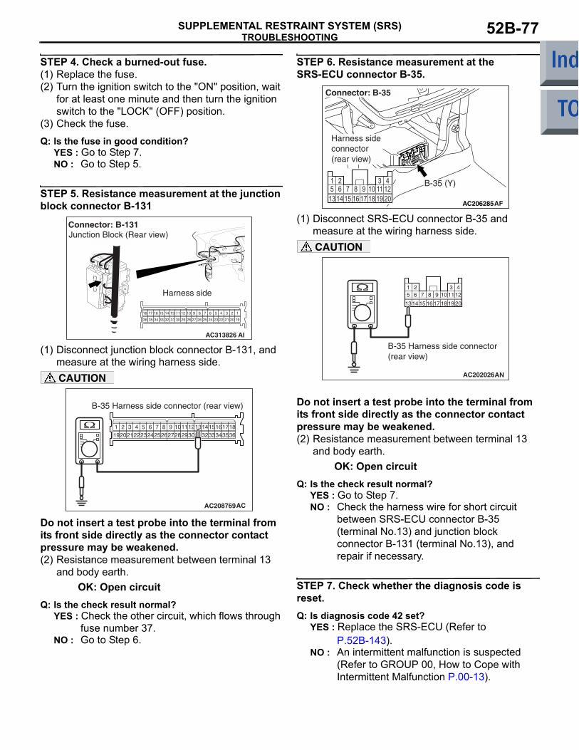
TROUBLESHOOTINGSUPPLEMENTAL RESTRAINT SYSTEM (SRS) 52B-77
STEP 4. Check a burned-out fuse.(1) Replace the fuse.(2) Turn the ignition switch to the "ON" position, wait
for at least one minute and then turn the ignition switch to the "LOCK" (OFF) position.
(3) Check the fuse.
Q: Is the fuse in good condition?YES : Go to Step 7.NO : Go to Step 5.
STEP 5. Resistance measurement at the junction block connector B-131
(1) Disconnect junction block connector B-131, and measure at the wiring harness side.CAUTION
Do not insert a test probe into the terminal from its front side directly as the connector contact pressure may be weakened.(2) Resistance measurement between terminal 13
and body earth.OK: Open circuit
Q: Is the check result normal?YES : Check the other circuit, which flows through
fuse number 37.NO : Go to Step 6.
STEP 6. Resistance measurement at the SRS-ECU connector B-35.
(1) Disconnect SRS-ECU connector B-35 and measure at the wiring harness side.CAUTION
Do not insert a test probe into the terminal from its front side directly as the connector contact pressure may be weakened.(2) Resistance measurement between terminal 13
and body earth.OK: Open circuit
Q: Is the check result normal?YES : Go to Step 7.NO : Check the harness wire for short circuit
between SRS-ECU connector B-35 (terminal No.13) and junction block connector B-131 (terminal No.13), and repair if necessary.
STEP 7. Check whether the diagnosis code is reset.Q: Is diagnosis code 42 set?
YES : Replace the SRS-ECU (Refer to P.52B-143).
NO : An intermittent malfunction is suspected (Refer to GROUP 00, How to Cope with Intermittent Malfunction P.00-13).
AC313826
Connector: B-131Junction Block (Rear view)
Harness side
AI
16342119
1202
28422
3235 9
27268 10 13
31123029
11 153332
143517
36187
25624
AC208769
B-35 Harness side connector (rear view)
AC
AC206285AF
B-35 (Y)
Connector: B-35
Harness side connector (rear view)
AC202026
1314 15 16 17 18 19 20
5 6 7 8 9 10 11121 2 3 4
B-35 Harness side connector (rear view)
AN

TROUBLESHOOTINGSUPPLEMENTAL RESTRAINT SYSTEM (SRS)52B-78
DIAGNOSIS CODE 43: SRS warning lamp circuit open-circuited (Lamp does not Illuminate).
OPERATION• Power for the SRS warning lamp is supplied from
the ignition switch (IG1) circuit.• The SRS warning lamp illuminates when the igni-
tion switch is turned to the "ON" position and goes out after approximately 7 seconds if there is not a malfunction in the SRS system.
DIAGNOSIS CODE SET CONDITIONSThis diagnosis code will be set if the SRS warning lamp driving circuit is short to earth. However, if the vehicle condition returns to normal, diagnosis code 43 will be automatically erased, and the SRS warn-ing lamp will go out.
AC510235
IGNITIONSWITCH (IG1)
COMBINATIONMETERMETER
ANDA/C-ECU
SRS-ECU
Wire colour codeB : Black LG : Light green G : Green L : Blue W : White Y : Yellow SB : Sky blueBR : Brown O : Orange GR : Grey R : Red P : Pink V : Violet
SRS Warning Lamp Drive Circuit
AB

TROUBLESHOOTINGSUPPLEMENTAL RESTRAINT SYSTEM (SRS) 52B-79
PROBABLE CAUSES• Damaged wiring harnesses of connectors• Malfunction of the SRS-ECU• Malfunction of the combination meter
DIAGNOSIS PROCEDURE
STEP 1. Check the SRS warning lamp.(1) Disconnect the negative battery terminal.
(2) Disconnected the SRS-ECU connector B-35.(3) Connect the negative battery terminal.(4) Turn the ignition switch to the "ON" position.
Q: Does the warning lamp illuminate?YES : Go to Step 3.NO : Go to Step 2.
STEP 2. Check the harness for short circuit to earth between ignition switch connector B-141 (terminal No.2) and combination meter B-14 (terminal No.31) and between combination meter B-14 (terminal No.26) and SRS-ECU connector B-35 (terminal No.18).
AC206285AF
B-35 (Y)
Connector: B-35
Harness side connector (rear view)
AC313828AG
Connector: B-141
Harness side connector (front view)
Clock spring
AC313822AP
Connector: B-14
Harness side connector (rear view)
B-14 (B)
AC206285AF
B-35 (Y)
Connector: B-35
Harness side connector (rear view)

TROUBLESHOOTINGSUPPLEMENTAL RESTRAINT SYSTEM (SRS)52B-80
NOTE:
Prior to the wiring harness inspection, check junction connector B-129, B-131 junction connector B-22 and repair if necessary.Q: Is the check result normal?
YES : . Replace the combination meter (Refer to GROUP 54A, Combination Meters Assembly P.54A-67).
NO : . Repair the harness wires between SRS-ECU connector B-35 (terminal No.18) and ignition switch connector (terminal No.2).
STEP 3. Check whether the diagnosis code is reset.Q: Is diagnosis code 43 set?
YES : Replace the SRS-ECU (Refer to P.52B-143).
NO : An intermittent malfunction is suspected (Refer to GROUP 00, How to Cope with Intermittent Malfunction P.00-13).
AC313827AH
B-131
B-131
B-129
Connectors: B-129, B-131Junction block (Rear view)
Harness side
Harness side
B-129
AC313822AQ
Connector: B-22

TROUBLESHOOTINGSUPPLEMENTAL RESTRAINT SYSTEM (SRS) 52B-81
diagnosis code 43: SRS warning lamp circuit open-circuited (Lamp does not Switch Off).
OPERATION• Power for the SRS warning lamp is supplied from
the ignition switch (IG1) circuit.• The SRS warning lamp illuminates when the igni-
tion switch is turned to the "ON" position and goes out after approximately 7 seconds if there is not a malfunction in the SRS system.
DIAGNOSIS CODE SET CONDITIONS• This diagnosis code will be set if an open circuit
has occurred in the wiring harness between the SRS warning lamp and the SRS-ECU. However, if the vehicle condition returns to normal, diagno-sis code 43 will be automatically erased, and the SRS warning lamp will go out.
AC510235
IGNITIONSWITCH (IG1)
COMBINATIONMETERMETER
ANDA/C-ECU
SRS-ECU
Wire colour codeB : Black LG : Light green G : Green L : Blue W : White Y : Yellow SB : Sky blueBR : Brown O : Orange GR : Grey R : Red P : Pink V : Violet
SRS Warning Lamp Drive Circuit
AB

TROUBLESHOOTINGSUPPLEMENTAL RESTRAINT SYSTEM (SRS)52B-82
TROUBLESHOOTING HINTS• Damaged wiring harnesses of connectors• Malfunction of the SRS-ECU• Malfunction of the combination meter
DIAGNOSIS PROCEDURE
STEP 1. M.U.T.-III actuator test.Use M.U.T.-III to perform the combination meter actuator tests.
• Item No.A0: Illuminate the indicator lamp and the warning lamp.
• Item No.A1: Extinguish the indicator lamps and the warning lamps.
Q: Does the warning lamp illuminate/extinguish?YES : Go to Step 2.NO : Replace the combination meter (Refer to
GROUP 54A, Combination Meters Assembly P.54A-67).
STEP 2. Check the harness for open circuit to earth between SRS-ECU connector B-35 (terminal No.18) and combination meter connector B-14 (terminal No.26).
Q: Is the check result normal?YES : Go to Step 3.NO : Repair the harness wire between SRS-ECU
connector B-35 (terminal No.18) and combination meter connector B-14 (terminal No.26).
STEP 3. Check whether the diagnosis code is reset.Q: Is diagnosis code 43 set?
YES : Replace the SRS-ECU (Refer to P.52B-143).
NO : An intermittent malfunction is suspected (Refer to GROUP 00, How to Cope with Intermittent Malfunction P.00-13).
AC206285AF
B-35 (Y)
Connector: B-35
Harness side connector (rear view)
AC313822AP
Connector: B-14
Harness side connector (rear view)
B-14 (B)
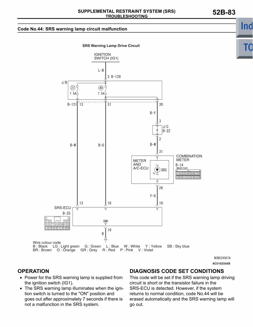
TROUBLESHOOTINGSUPPLEMENTAL RESTRAINT SYSTEM (SRS) 52B-83
Code No.44: SRS warning lamp circuit malfunction
OPERATION• Power for the SRS warning lamp is supplied from
the ignition switch (IG1).• The SRS warning lamp illuminates when the igni-
tion switch is turned to the "ON" position and goes out after approximately 7 seconds if there is not a malfunction in the SRS system.
DIAGNOSIS CODE SET CONDITIONSThis code will be set if the SRS warning lamp driving circuit is short or the transistor failure in the SRS-ECU is detected. However, if the system returns to normal condition, code No.44 will be erased automatically and the SRS warning lamp will go out.
AC510235
IGNITIONSWITCH (IG1)
COMBINATIONMETERMETER
ANDA/C-ECU
SRS-ECU
Wire colour codeB : Black LG : Light green G : Green L : Blue W : White Y : Yellow SB : Sky blueBR : Brown O : Orange GR : Grey R : Red P : Pink V : Violet
SRS Warning Lamp Drive Circuit
AB

TROUBLESHOOTINGSUPPLEMENTAL RESTRAINT SYSTEM (SRS)52B-84
PROBABLE CAUSES• Damaged wiring harnesses of connectors• Malfunction of the SRS-ECU
DIAGNOSIS PROCEDURECheck the SRS warning lamp drive circuit system. Refer to P.52B-78.
Code No.61: Driver's air bag module (squib) system (short-circuited to the power supply)
OPERATION• The SRS-ECU judges how severe a collision is
by detecting signals from the front impact sensors and the front air bag analogue G-sensor. If the impact is over a predetermined level, the SRS-ECU sends an ignition signal. At this time, if the front air bag safing G-sensor is on, the SRS air bag will inflate.
• The ignition signal is input to the air bag module via the clock spring to inflate the air bag.
DIAGNOSIS CODE SET CONDITIONSThis diagnosis code is set if the drivers air bag squib wire(s) are short-circuited to the power supply.
PROBABLE CAUSES• Malfunction of the clock spring• Damaged harness wires and connectors• Short to the power supply in the driver's air bag
module (squib) harness• Malfunction of the SRS-ECU
AC510223
Wire colour codeB : Black LG : Light green G : Green L : Blue W : White Y : Yellow SB : Sky blueBR : Brown O : Orange GR : Grey R : Red P : Pink V : Violet
AIR BAG MODULE(SQUIB)(DRIVER'S SIDE)
CONNECTORLOCK SWITCH
CONNECTORLOCK SWITCH
CLOCK SPRING
SRS-ECU
CONNECTORLOCK SWITCH
NOTE: CONNECTOR COUPLED: ON CONNECTOR UNCOUPLED: OFF
Driver's Air Bag Module (Squib) Circuit
AB

TROUBLESHOOTINGSUPPLEMENTAL RESTRAINT SYSTEM (SRS) 52B-85
DIAGNOSIS PROCEDURE
STEP 1. Check the diagnosis code by connecting a dummy resistor. (M.U.T.-III diagnosis code)(1) Disconnect the negative battery terminal.
(2) By sliding the A section (in the figure) of air bag module connector B-138 in arrow direction, disconnect the connector.
(3) Connect special tool dummy resistor (MB991865) to special tool resistor harness (MB991866).CAUTION
Do not insert a test probe into the terminal from its front side directly as the connector contact pressure may be weakened.(4) Insert special tool (MB991866) into clock spring
side air bag module connector B-138 by backprobing.
(5) Connect the negative battery terminal.
(6) Erase the diagnosis code memory, and check the diagnosis code.
Q: Is diagnosis code 61 out put?YES : Go to Step 2.NO : Replace the drivers air bag module (Refer
to P.52B-145).
STEP 2. Check the diagnosis code by connecting a dummy resistor. (M.U.T.-III diagnosis code)(1) Disconnect the negative battery terminal.
(2) Disconnect the clock spring connector B-136.
(3) Connect special tool dummy resistor (MB991865) to special tool resistor harness (MB991866).CAUTION
Do not insert a test probe into the terminal from its front side directly as the connector contact pressure may be weakened.(4) Insert special tool (MB991866) into clock spring
harness side connector B-136 (terminal No.3 and 4) by backprobing.
(5) Connect the negative battery terminal.(6) Erase the diagnosis code memory, and check the
diagnosis code.
Q: Is diagnosis code 61 set?YES : Go to Step 3.NO : Replace the clock spring (Refer to
P.52B-145).
AC105823
AC304700
AC305145AF
A
Steeringwheel
B-138 Air bag module connector
AC300945AG
MB991865(Dummy resistor : 3Ω)
MB991866(Resistor harness)
B-138 Air bag moduleconnector
AC313828 AF
Connectors: B-136
B-136
Harness side connector (rear view)
AC300949 AF
MB991865 (Dummyresistor : 3 Ω) MB991866
(Resistor harness)
B-136 Clock springconnector(Rear view)

TROUBLESHOOTINGSUPPLEMENTAL RESTRAINT SYSTEM (SRS)52B-86
STEP 3. Voltage measurement at the SRS-ECU connector B-35.(1) Disconnect the negative battery terminal.
(2) Disconnect SRS-ECU connector B-35.DANGER
To prevents the air bag from deploying unin-tentionally, disconnect the clock spring con-nector B-136 to short the squib circuit.(3) Disconnect the clock spring connector B-136.(4) Connect the negative battery terminal.
(5) Turn the ignition switch to the "ON" position.CAUTION
Do not insert a test probe into the terminal from its front side directly as the connector contact pressure may be weakened.(6) Voltage measurement between B-35 harness
side connector terminals 11, 12 and body earth.OK: 0 V
Q: Is the check result normal?YES : Go to Step 4.NO : Repair the harness wires between
SRS-ECU connector B-35 (terminal No.11 and 12) and clock spring connector B-136 (terminal No.3 and 4).
STEP 4. Check whether the diagnosis code is reset.Q: Is diagnosis code 61 set?
YES : Replace the SRS-ECU (Refer to P.52B-143).
NO : An intermittent malfunction is suspected (Refer to GROUP 00, How to Cope with Intermittent Malfunction P.00-13).
AC206285AF
B-35 (Y)
Connector: B-35
Harness side connector (rear view)
AC313828 AF
Connectors: B-136
B-136
Harness side connector (rear view)
AC006255
13 14 15 16 17 18 19 205 6 7 8 9 10 11 121 2 3 4
AV
B-35 Harness side connector (rear view)

TROUBLESHOOTINGSUPPLEMENTAL RESTRAINT SYSTEM (SRS) 52B-87
Code No.62: Driver's air bag module (squib) system (short-circuited to the earth)
OPERATION• The SRS-ECU judges how severe a collision is
by detecting signals from the front impact sensors and the front air bag analogue G-sensor. If the impact is over a predetermined level, the SRS-ECU sends an ignition signal. At this time, if the front air bag safing G-sensor is on, the SRS air bag will inflate.
• The ignition signal is input to the air bag module via the clock spring to inflate the air bag.
DIAGNOSIS CODE SET CONDITIONSThis diagnosis code is set if the driver's air bag squib wire(s) are short-circuited to the earth.
PROBABLE CAUSES• Malfunction of the clock spring• Damaged harness wires and connectors• Short to the earth in the driver's air bag module
(squib) harness• Malfunction of the SRS-ECU
AC510223
Wire colour codeB : Black LG : Light green G : Green L : Blue W : White Y : Yellow SB : Sky blueBR : Brown O : Orange GR : Grey R : Red P : Pink V : Violet
AIR BAG MODULE(SQUIB)(DRIVER'S SIDE)
CONNECTORLOCK SWITCH
CONNECTORLOCK SWITCH
CLOCK SPRING
SRS-ECU
CONNECTORLOCK SWITCH
NOTE: CONNECTOR COUPLED: ON CONNECTOR UNCOUPLED: OFF
Driver's Air Bag Module (Squib) Circuit
AB

TROUBLESHOOTINGSUPPLEMENTAL RESTRAINT SYSTEM (SRS)52B-88
DIAGNOSIS PROCEDURE
STEP 1. Check the diagnosis code by connecting a dummy resistor. (M.U.T.-III diagnosis code)(1) Disconnect the negative battery terminal.
(2) By sliding the A section (in the figure) of air bag module connector B-138 in arrow direction, disconnect the connector.
(3) Connect special tool dummy resistor (MB991865) to special tool resistor harness (MB991866).CAUTION
Do not insert a test probe into the terminal from its front side directly as the connector contact pressure may be weakened.(4) Insert special tool (MB991866) into clock spring
side air bag module connector B-138 by backprobing.
(5) Connect the negative battery terminal.
(6) Erase the diagnosis code memory, and check the diagnosis code.
Q: Is diagnosis code 62 out put?YES : Go to Step 2.NO : Replace the drivers air bag module (Refer
to P.52B-145).
STEP 2. Check the diagnosis code by connecting a dummy resistor. (M.U.T.-III diagnosis code)(1) Disconnect the negative battery terminal.
(2) Disconnect the clock spring connector B-136.
(3) Connect special tool dummy resistor (MB991865) to special tool resistor harness (MB991866).CAUTION
Do not insert a test probe into the terminal from its front side directly as the connector contact pressure may be weakened.(4) Insert special tool (MB991866) into clock spring
harness side connector B-136 (terminal No.3 and 4) by backprobing.
(5) Connect the negative battery terminal.(6) Erase the diagnosis code memory, and check the
diagnosis code.
Q: Is diagnosis code 62 set?YES : Go to Step 3.NO : Replace the clock spring (Refer to
P.52B-145).
AC105823
AC304700
AC305145AF
A
Steeringwheel
B-138 Air bag module connector
AC300945AG
MB991865(Dummy resistor : 3Ω)
MB991866(Resistor harness)
B-138 Air bag moduleconnector
AC313828 AF
Connectors: B-136
B-136
Harness side connector (rear view)
AC300949 AF
MB991865 (Dummyresistor : 3 Ω) MB991866
(Resistor harness)
B-136 Clock springconnector(Rear view)
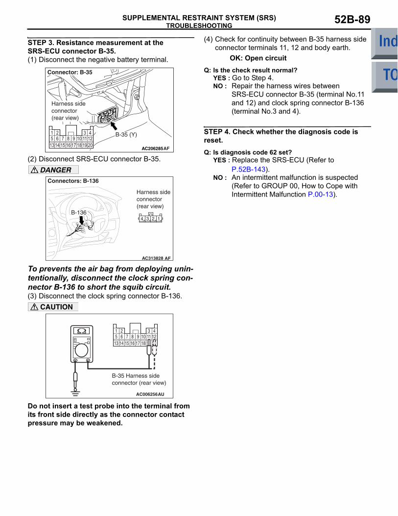
TROUBLESHOOTINGSUPPLEMENTAL RESTRAINT SYSTEM (SRS) 52B-89
STEP 3. Resistance measurement at the SRS-ECU connector B-35.(1) Disconnect the negative battery terminal.
(2) Disconnect SRS-ECU connector B-35.DANGER
To prevents the air bag from deploying unin-tentionally, disconnect the clock spring con-nector B-136 to short the squib circuit.(3) Disconnect the clock spring connector B-136.
CAUTION
Do not insert a test probe into the terminal from its front side directly as the connector contact pressure may be weakened.
(4) Check for continuity between B-35 harness side connector terminals 11, 12 and body earth.
OK: Open circuitQ: Is the check result normal?
YES : Go to Step 4.NO : Repair the harness wires between
SRS-ECU connector B-35 (terminal No.11 and 12) and clock spring connector B-136 (terminal No.3 and 4).
STEP 4. Check whether the diagnosis code is reset.Q: Is diagnosis code 62 set?
YES : Replace the SRS-ECU (Refer to P.52B-143).
NO : An intermittent malfunction is suspected (Refer to GROUP 00, How to Cope with Intermittent Malfunction P.00-13).
AC206285AF
B-35 (Y)
Connector: B-35
Harness side connector (rear view)
AC313828 AF
Connectors: B-136
B-136
Harness side connector (rear view)
AC006256
13 14 15 16 17 18 19 205 6 7 8 9 10 11 121 2 3 4
AU
B-35 Harness side connector (rear view)

TROUBLESHOOTINGSUPPLEMENTAL RESTRAINT SYSTEM (SRS)52B-90
Code No.64: Passenger's (front) air bag module (squib) system (short-circuited to the power supply)
OPERATION• The SRS-ECU judges how severe a collision is
by detecting signals from the front impact sensors and the front air bag analogue G-sensor. If the impact is over a predetermined level, the SRS-ECU sends an ignition signal. At this time, if the front air bag safing G-sensor is on, the SRS air bag will inflate.
• The ignition signal is input to the air bag module to inflate the air bag.
DIAGNOSIS CODE SET CONDITIONSThis diagnosis code is set if the passenger's (front) air bag squib wire(s) are short-circuited to the power supply.
PROBABLE CAUSES• Damaged harness wires and connectors• Short to the power supply in the passenger's
(front) air bag module (squib) harness• Malfunction of the SRS-ECU
DIAGNOSIS PROCEDURE
STEP1. Check the diagnosis code by connecting a dummy resistor. (M.U.T.-III diagnosis code)(1) Disconnect the negative battery terminal.
(2) Unclip passengers (front) air bag module connector B-06.
AC510225
CONNECTORLOCK SWITCH
AIR BAG MODULE(SQIUB)(PASSENGER'S SIDE)
SRS-ECU
CONNECTORLOCK SWITCH
Wire colour codeB : Black LG : Light green G : Green L : Blue W : White Y : Yellow SB : Sky blueBR : Brown O : Orange GR : Grey R : Red P : Pink V : Violet
NOTE: CONNECTOR COUPLED: ON CONNECTOR UNCOUPLED: OFF
Passenger's (Front) Air Bag Module (Squib) Circuit
AB
AC206286
Connector: B-06
2 1
Harness side connector (front view) B-06 (R)
AE
Glove box striker

TROUBLESHOOTINGSUPPLEMENTAL RESTRAINT SYSTEM (SRS) 52B-91
(3) Connect special tool dummy resistor (MB991865) to special tool resistor harness (MB991866).CAUTION
Do not insert a test probe into the terminal from its front side directly as the connector contact pressure may be weakened.(4) Disconnect the passenger's (front) air bag
module connector B-06, and insert special tool (MB991866) into the harness side connector by backprobing.
(5) Connect the negative battery terminal.(6) Erase the diagnosis code memory, and check the
diagnosis code.
Q: Is diagnosis code 64 set?YES : Go to Step 2.NO : Replace the passenger's (front) air bag
module (Refer to P.52B-145).
STEP 2. Voltage measurement at the SRS-ECU connector B-35.(1) Disconnect the negative battery terminal.
(2) Disconnect SRS-ECU connector B-35.CAUTION
To prevents the air bag from deploying uninten-tionally, disconnect the passengers (front) air bag module connector B-06 to short the squib circuit.(3) Disconnect the passenger's (front) air bag
module connector B-06.(4) Connect the negative battery terminal.(5) Turn the ignition switch to the "ON" position.
CAUTION
Do not insert a test probe into the terminal from its front side directly as the connector contact pressure may be weakened.
AC300956AN
MB991865(Dummy resistor: 3 )
MB991866 (Resistor harness)
B-06 Passenger's (front) air bag module connector
B-06 Harness side connector
AC206285AF
B-35 (Y)
Connector: B-35
Harness side connector (rear view)
AC206286
Connector: B-06
2 1
Harness side connector (front view) B-06 (R)
AE
Glove box striker
13 14 15 16 17 18 19 205 6 7 8 9 10 11 121 2 3 4
AC006257AT
B-35 Harness side connector (rear view)
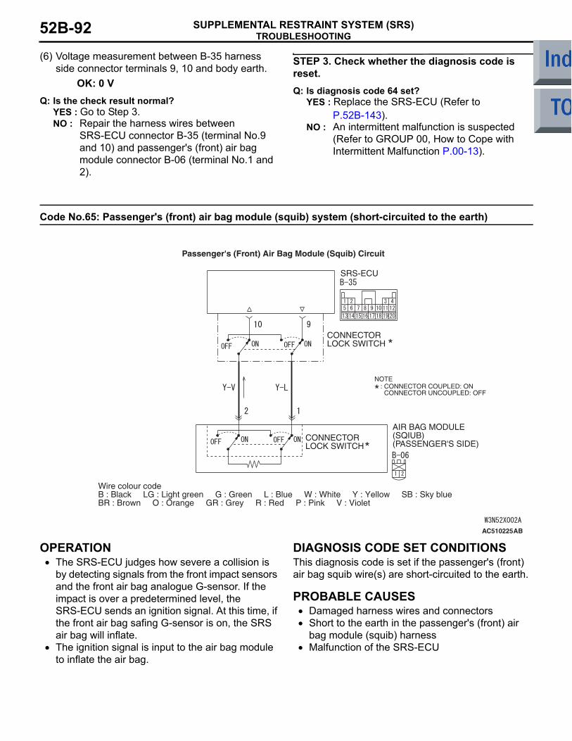
TROUBLESHOOTINGSUPPLEMENTAL RESTRAINT SYSTEM (SRS)52B-92
(6) Voltage measurement between B-35 harness side connector terminals 9, 10 and body earth.
OK: 0 VQ: Is the check result normal?
YES : Go to Step 3.NO : Repair the harness wires between
SRS-ECU connector B-35 (terminal No.9 and 10) and passenger's (front) air bag module connector B-06 (terminal No.1 and 2).
STEP 3. Check whether the diagnosis code is reset.Q: Is diagnosis code 64 set?
YES : Replace the SRS-ECU (Refer to P.52B-143).
NO : An intermittent malfunction is suspected (Refer to GROUP 00, How to Cope with Intermittent Malfunction P.00-13).
Code No.65: Passenger's (front) air bag module (squib) system (short-circuited to the earth)
OPERATION• The SRS-ECU judges how severe a collision is
by detecting signals from the front impact sensors and the front air bag analogue G-sensor. If the impact is over a predetermined level, the SRS-ECU sends an ignition signal. At this time, if the front air bag safing G-sensor is on, the SRS air bag will inflate.
• The ignition signal is input to the air bag module to inflate the air bag.
DIAGNOSIS CODE SET CONDITIONSThis diagnosis code is set if the passenger's (front) air bag squib wire(s) are short-circuited to the earth.
PROBABLE CAUSES• Damaged harness wires and connectors• Short to the earth in the passenger's (front) air
bag module (squib) harness• Malfunction of the SRS-ECU
AC510225
CONNECTORLOCK SWITCH
AIR BAG MODULE(SQIUB)(PASSENGER'S SIDE)
SRS-ECU
CONNECTORLOCK SWITCH
Wire colour codeB : Black LG : Light green G : Green L : Blue W : White Y : Yellow SB : Sky blueBR : Brown O : Orange GR : Grey R : Red P : Pink V : Violet
NOTE: CONNECTOR COUPLED: ON CONNECTOR UNCOUPLED: OFF
Passenger's (Front) Air Bag Module (Squib) Circuit
AB
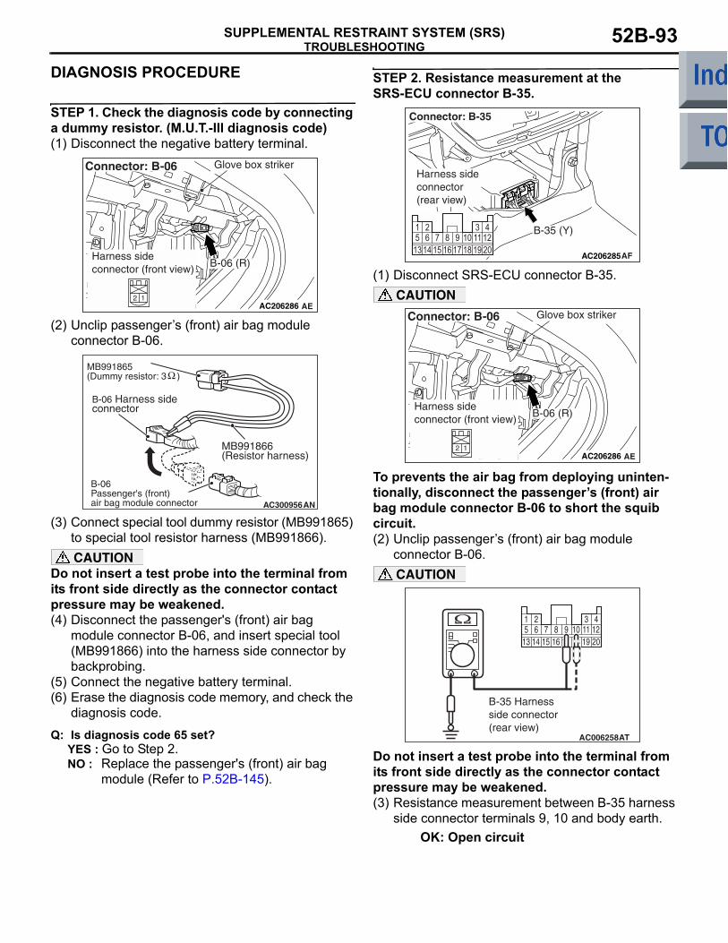
TROUBLESHOOTINGSUPPLEMENTAL RESTRAINT SYSTEM (SRS) 52B-93
DIAGNOSIS PROCEDURE
STEP 1. Check the diagnosis code by connecting a dummy resistor. (M.U.T.-III diagnosis code)(1) Disconnect the negative battery terminal.
(2) Unclip passengers (front) air bag module connector B-06.
(3) Connect special tool dummy resistor (MB991865) to special tool resistor harness (MB991866).CAUTION
Do not insert a test probe into the terminal from its front side directly as the connector contact pressure may be weakened.(4) Disconnect the passenger's (front) air bag
module connector B-06, and insert special tool (MB991866) into the harness side connector by backprobing.
(5) Connect the negative battery terminal.(6) Erase the diagnosis code memory, and check the
diagnosis code.
Q: Is diagnosis code 65 set?YES : Go to Step 2.NO : Replace the passenger's (front) air bag
module (Refer to P.52B-145).
STEP 2. Resistance measurement at the SRS-ECU connector B-35.
(1) Disconnect SRS-ECU connector B-35.CAUTION
To prevents the air bag from deploying uninten-tionally, disconnect the passengers (front) air bag module connector B-06 to short the squib circuit.(2) Unclip passengers (front) air bag module
connector B-06.CAUTION
Do not insert a test probe into the terminal from its front side directly as the connector contact pressure may be weakened.(3) Resistance measurement between B-35 harness
side connector terminals 9, 10 and body earth.OK: Open circuit
AC206286
Connector: B-06
2 1
Harness side connector (front view) B-06 (R)
AE
Glove box striker
AC300956AN
MB991865(Dummy resistor: 3 )
MB991866 (Resistor harness)
B-06 Passenger's (front) air bag module connector
B-06 Harness side connector
AC206285AF
B-35 (Y)
Connector: B-35
Harness side connector (rear view)
AC206286
Connector: B-06
2 1
Harness side connector (front view) B-06 (R)
AE
Glove box striker
AC006258
13 14 15 16 17 18 19 205 6 7 8 9 10 11 121 2 3 4
AT
B-35 Harness side connector (rear view)

TROUBLESHOOTINGSUPPLEMENTAL RESTRAINT SYSTEM (SRS)52B-94
Q: Is the check result normal? YES : Go to Step 3.NO : Repair the harness wires between
SRS-ECU connector B-35 (terminal No.9 and 10) and passenger's (front) air bag module connector B-06 (terminal No.1 and 2).
STEP 3. Check whether the diagnosis code is reset.Q: Is diagnosis code 65 set?
YES : Replace the SRS-ECU (Refer to P.52B-143).
NO : An intermittent malfunction is suspected (Refer to GROUP 00, How to Cope with Intermittent Malfunction P.00-13).
Code No.66: Driver's seat belt pre-tensioner (squib) system (short-circuited to the power supply)
OPERATIONThe SRS-ECU judges how severe a collision is by detecting signals from the front impact sensors and the front air bag analogue G-sensor. If the impact is over a predetermined level, the SRS-ECU sends an ignition signal. At this time, if the front air bag safing G-sensor is on, the pre-tensioner will deploy.
DIAGNOSIS CODE SET CONDITIONSThis diagnosis code is set if the driver's seat belt pre-tensioner wire(s) are short-circuited to the power supply.
PROBABLE CAUSES• Damaged wiring harnesses or connectors• Short to the power supply in the driver's seat belt
pre-tensioner (squib) harness• Malfunction of the SRS-ECU
AC510230
Wire colour codeB : Black LG : Light green G : Green L : Blue W : White Y : Yellow SB : Sky blueBR : Brown O : Orange GR : Grey R : Red P : Pink V : Violet
SEAT BELTPRETENSIONER(RH)
SRS-ECU
CONNECTORLOCK SWITCH
CONNECTORLOCK SWITCH
NOTE: CONNECTOR COUPLED: ON CONNECTOR UNCOUPLED: OFF
Driver's Seat Belt Pre-Tensioner (Squib)
AB

TROUBLESHOOTINGSUPPLEMENTAL RESTRAINT SYSTEM (SRS) 52B-95
DIAGNOSIS PROCEDURE
STEP 1. Check the diagnosis code by connecting a dummy resistor. (M.U.T.-III diagnosis code)(1) Disconnect the negative battery terminal.
(2) Disconnect driver's seat belt pre-tensioner connector C-28. Use a flat-tipped screwdriver to pull out the locking button at the harness side connector, and then disconnect the connector.
(3) Connect special tool dummy resistor (MB991865) to special tool resistor harness (MB991884).
(4) Connect special tool (MB991884) to the C-28 harness side connector.
(5) Connect the negative battery terminal.(6) Erase diagnosis code memory, and check the
diagnosis code.
Q: Is diagnosis code 66 set?YES : Go to Step 2.NO : Replace the driver's seat belt with
pre-tensioner (Refer to P.52B-159).
STEP 2. Voltage measurement at the SRS-ECU connector B-35.(1) Disconnect the negative battery terminal.
(2) Disconnect SRS-ECU connector B-35.DANGER
To prevents the air bag from deploying unin-tentionally, disconnect the drivers seat belt pre-tensioner connector C-28 to short the squib circuit.(3) Disconnect driver's seat belt pre-tensioner
connector C-28. Use a flat-tipped screwdriver to pull out the locking button at the harness side connector, and then disconnect the connector.
(4) Connect the negative battery terminal.
AC207222 AF
Harness side connector (front view)
Connector: C-28
C-28 (B) Centrepillar
AC208430AE
Pre-tensionerconnector
Locking button
Harness side connector
Flat-tipped screwdriver
MB991865(Dummy resistor : 3 Ω)
C-28 Harness side connectors
MB991884(Resistorharness)
AF
AC206285AF
B-35 (Y)
Connector: B-35
Harness side connector (rear view)
AC207222 AF
Harness side connector (front view)
Connector: C-28
C-28 (B) Centrepillar
AC208430AE
Pre-tensionerconnector
Locking button
Harness side connector
Flat-tipped screwdriver
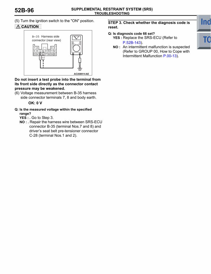
TROUBLESHOOTINGSUPPLEMENTAL RESTRAINT SYSTEM (SRS)52B-96
(5) Turn the ignition switch to the "ON" position.CAUTION
Do not insert a test probe into the terminal from its front side directly as the connector contact pressure may be weakened.(6) Voltage measurement between B-35 harness
side connector terminals 7, 8 and body earth.OK: 0 V
Q: Is the measured voltage within the specified range?YES : . Go to Step 3.NO : . Repair the harness wire between SRS-ECU
connector B-35 (terminal Nos.7 and 8) and drivers seat belt pre-tensioner connector C-28 (terminal Nos.1 and 2).
STEP 3. Check whether the diagnosis code is reset.Q: Is diagnosis code 66 set?
YES : Replace the SRS-ECU (Refer to P.52B-143).
NO : An intermittent malfunction is suspected (Refer to GROUP 00, How to Cope with Intermittent Malfunction P.00-13). 13 14 16 17 19 20
5 6 7 8 9 10 11 121 2 3 4
1815
AC208914AE
B-35 Harness side connector (rear view)

TROUBLESHOOTINGSUPPLEMENTAL RESTRAINT SYSTEM (SRS) 52B-97
Code No.67: Driver's seat belt pre-tensioner (squib) system (short-circuited to the earth)
OPERATIONThe SRS-ECU judges how severe a collision is by detecting signals from the front impact sensors and the front air bag analogue G-sensor. If the impact is over a predetermined level, the SRS-ECU sends an ignition signal. At this time, if the front air bag safing G-sensor is on, the pre-tensioner will deploy.
DIAGNOSIS CODE SET CONDITIONSThis diagnosis code is set if the driver's seat belt pre-tensioner wire(s) are short-circuited to the earth.
PROBABLE CAUSES• Damaged wiring harnesses or connectors• Short to the earth in the driver's seat belt pre-ten-
sioner (squib) harness• Malfunction of the SRS-ECU
AC510230
Wire colour codeB : Black LG : Light green G : Green L : Blue W : White Y : Yellow SB : Sky blueBR : Brown O : Orange GR : Grey R : Red P : Pink V : Violet
SEAT BELTPRETENSIONER(RH)
SRS-ECU
CONNECTORLOCK SWITCH
CONNECTORLOCK SWITCH
NOTE: CONNECTOR COUPLED: ON CONNECTOR UNCOUPLED: OFF
Driver's Seat Belt Pre-Tensioner (Squib)
AB
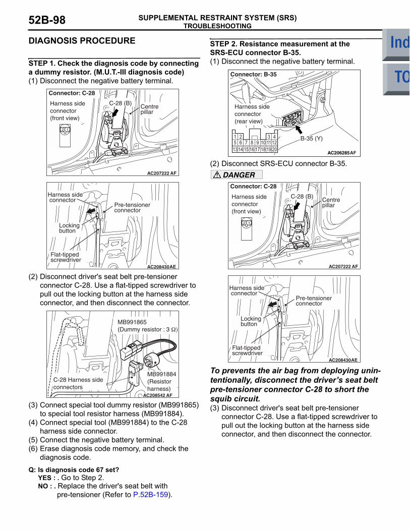
TROUBLESHOOTINGSUPPLEMENTAL RESTRAINT SYSTEM (SRS)52B-98
DIAGNOSIS PROCEDURE
STEP 1. Check the diagnosis code by connecting a dummy resistor. (M.U.T.-III diagnosis code)(1) Disconnect the negative battery terminal.
(2) Disconnect driver's seat belt pre-tensioner connector C-28. Use a flat-tipped screwdriver to pull out the locking button at the harness side connector, and then disconnect the connector.
(3) Connect special tool dummy resistor (MB991865) to special tool resistor harness (MB991884).
(4) Connect special tool (MB991884) to the C-28 harness side connector.
(5) Connect the negative battery terminal.(6) Erase diagnosis code memory, and check the
diagnosis code.
Q: Is diagnosis code 67 set?YES : . Go to Step 2.NO : . Replace the driver's seat belt with
pre-tensioner (Refer to P.52B-159).
STEP 2. Resistance measurement at the SRS-ECU connector B-35.(1) Disconnect the negative battery terminal.
(2) Disconnect SRS-ECU connector B-35.DANGER
To prevents the air bag from deploying unin-tentionally, disconnect the drivers seat belt pre-tensioner connector C-28 to short the squib circuit.(3) Disconnect driver's seat belt pre-tensioner
connector C-28. Use a flat-tipped screwdriver to pull out the locking button at the harness side connector, and then disconnect the connector.
AC207222 AF
Harness side connector (front view)
Connector: C-28
C-28 (B) Centrepillar
AC208430AE
Pre-tensionerconnector
Locking button
Harness side connector
Flat-tipped screwdriver
MB991865(Dummy resistor : 3 Ω)
C-28 Harness side connectors
MB991884(Resistorharness)
AF
AC206285AF
B-35 (Y)
Connector: B-35
Harness side connector (rear view)
AC207222 AF
Harness side connector (front view)
Connector: C-28
C-28 (B) Centrepillar
AC208430AE
Pre-tensionerconnector
Locking button
Harness side connector
Flat-tipped screwdriver

TROUBLESHOOTINGSUPPLEMENTAL RESTRAINT SYSTEM (SRS) 52B-99
CAUTION
Do not insert a test probe into the terminal from its front side directly as the connector contact pressure may be weakened.(4) Resistance measurement between B-35 harness
side connector terminals 7, 8 and body earth.OK: Open circuit
Q: Is the check result normal?YES : . Go to Step 3.NO : . Repair the harness wire between SRS-ECU
connector B-35 (terminal Nos.7 and 8) and drivers seat belt pre-tensioner connector C-28 (terminal Nos.1 and 2).
STEP 3. Check whether the diagnosis code is reset.Q: Is diagnosis code 67 set?
YES : Replace the SRS-ECU (Refer to P.52B-143).
NO : An intermittent malfunction is suspected (Refer to GROUP 00, How to Cope with Intermittent Malfunction P.00-13).
Code No.68: Passenger's (front) seat belt pre-tensioner (squib) system (short-circuited to the power supply)
13 14 16 17 19 205 6 7 8 9 10 11 121 2 3 4
1815
AC208915
B-35 Harness side connector (rear view)
AE
AC510233
Wire colour codeB : Black LG : Light green G : Green L : Blue W : White Y : Yellow SB : Sky blueBR : Brown O : Orange GR : Grey R : Red P : Pink V : Violet
SEAT BELTPRETENSIONER(LH)
SRS-ECU
CONNECTORLOCK SWITCH
CONNECTORLOCK SWITCH
NOTE: CONNECTOR COUPLED: ON CONNECTOR UNCOUPLED: OFF
Passenger's (Front) Seat Belt Pre-tensioner (Squib)
AB

TROUBLESHOOTINGSUPPLEMENTAL RESTRAINT SYSTEM (SRS)52B-100
OPERATIONThe SRS-ECU judges how severe a collision is by detecting signals from the front impact sensors and the front air bag analogue G-sensor. If the impact is over a predetermined level, the SRS-ECU sends an ignition signal. At this time, if the front air bag safing G-sensor is on, the pre-tensioner will deploy.
DIAGNOSIS CODE SET CONDITIONSThis diagnosis code is set if passenger's (front) seat belt pre-tensioner wire(s) are short-circuited to the power supply.
PROBABLE CAUSES• Damaged wiring harnesses or connectors• Short to the power supply in the passenger's
(front) seat belt pre-tensioner (squib) harness• Malfunction of the SRS-ECU
DIAGNOSIS PROCEDURE
STEP 1. Check the diagnosis code by connecting a dummy resistor. (M.U.T.-III diagnosis code)(1) Disconnect the negative battery terminal.
(2) Disconnect passenger's (front) seat belt pre-tensioner connector C-20. Use a flat-tipped screwdriver to pull out the locking button at the harness side connector, and then disconnect the connector.
(3) Connect special tool dummy resistor (MB991865) to special tool resistor harness (MB991884).
(4) Connect special tool (MB991884) to the C-20 harness side connector.
(5) Connect the negative battery terminal.(6) Erase diagnosis code memory, and then check
the diagnosis code.
Q: Is diagnosis code 68 set?YES : Go to Step 2.NO : Replace the passenger's (front) seat belt
pre-tensioner (Refer to P.52B-159).
AC207223 AE
Harness side connector (front view)
Connector: C-20
C-20 (B) Centrepillar
AC208430AE
Pre-tensionerconnector
Locking button
Harness side connector
Flat-tipped screwdriver
AC201287BQ
C-20 Harness sideconnector
MB991884

TROUBLESHOOTINGSUPPLEMENTAL RESTRAINT SYSTEM (SRS) 52B-101
STEP 2. Voltage measurement at the SRS-ECU connector B-35.(1) Disconnect the negative battery terminal.
(2) Disconnect SRS-ECU connector B-35.
DANGERTo prevents the air bag from deploying unin-tentionally, disconnect the passenger's (front) seat belt pre-tensioner connector C-20 to short the squib circuit.(3) Disconnect passenger's (front) seat belt
pre-tensioner connector C-20. Use a flat-tipped screwdriver to pull out the locking button at the harness side connector, and then disconnect the connector.
(4) Connect the negative battery terminal.(5) Turn the ignition switch to the "ON" position,
CAUTION
Do not insert a test probe into the terminal from its front side directly as the connector contact pressure may be weakened.(6) Voltage measurement between B-35 harness
side connector terminals 5, 6 and body earth.OK: 0 V
Q: Is the check result normal?YES : Go to Step 3.NO : Repair the harness wires between
SRS-ECU connector B-35 (terminal No.5 and 6) and passenger's (front) seat belt pre-tensioner connector C-20 (terminal No.1 and 2).
STEP 3. Check whether the diagnosis code is reset.Q: Is diagnosis code 68 set?
YES : Replace the SRS-ECU (Refer to P.52B-143).
NO : An intermittent malfunction is suspected (Refer to GROUP 00, How to Cope with Intermittent Malfunction P.00-13).
AC206285AF
B-35 (Y)
Connector: B-35
Harness side connector (rear view)
AC207223 AE
Harness side connector (front view)
Connector: C-20
C-20 (B) Centrepillar
AC208430AE
Pre-tensionerconnector
Locking button
Harness side connector
Flat-tipped screwdriver
13 14 16 17 19 205 6 7 8 9 10 11 121 2 3 4
1815
AC208912
B-35 Harness side connector (rear view)
AE

TROUBLESHOOTINGSUPPLEMENTAL RESTRAINT SYSTEM (SRS)52B-102
Code No.69: Passenger's (front) seat belt pre-tensioner (squib) system (short-circuited to the earth)
OPERATIONThe SRS-ECU judges how severe a collision is by detecting signals from the front impact sensors and the front air bag analogue G-sensor. If the impact is over a predetermined level, the SRS-ECU sends an ignition signal. At this time, if the front air bag safing G-sensor is on, the pre-tensioner will deploy.
DIAGNOSIS CODE SET CONDITIONSThis diagnosis code is set if passenger's (front) seat belt pre-tensioner wire(s) are short-circuited to the earth.
PROBABLE CAUSES• Damaged wiring harnesses or connectors• Short to the earth in the passenger's (front) seat
belt pre-tensioner (squib) harness• Malfunction of the SRS-ECU
AC510233
Wire colour codeB : Black LG : Light green G : Green L : Blue W : White Y : Yellow SB : Sky blueBR : Brown O : Orange GR : Grey R : Red P : Pink V : Violet
SEAT BELTPRETENSIONER(LH)
SRS-ECU
CONNECTORLOCK SWITCH
CONNECTORLOCK SWITCH
NOTE: CONNECTOR COUPLED: ON CONNECTOR UNCOUPLED: OFF
Passenger's (Front) Seat Belt Pre-tensioner (Squib)
AB
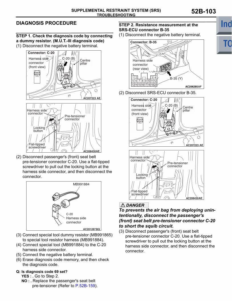
TROUBLESHOOTINGSUPPLEMENTAL RESTRAINT SYSTEM (SRS) 52B-103
DIAGNOSIS PROCEDURE
STEP 1. Check the diagnosis code by connecting a dummy resistor. (M.U.T.-III diagnosis code)(1) Disconnect the negative battery terminal.
(2) Disconnect passenger's (front) seat belt pre-tensioner connector C-20. Use a flat-tipped screwdriver to pull out the locking button at the harness side connector, and then disconnect the connector.
(3) Connect special tool dummy resistor (MB991865) to special tool resistor harness (MB991884).
(4) Connect special tool (MB991884) to the C-20 harness side connector.
(5) Connect the negative battery terminal.(6) Erase diagnosis code memory, and then check
the diagnosis code.
Q: Is diagnosis code 69 set?YES : . Go to Step 2.NO : . Replace the passenger's seat belt
pre-tensioner (Refer to P.52B-159).
STEP 2. Resistance measurement at the SRS-ECU connector B-35(1) Disconnect the negative battery terminal.
(2) Disconnect SRS-ECU connector B-35.
DANGERTo prevents the air bag from deploying unin-tentionally, disconnect the passenger's (front) seat belt pre-tensioner connector C-20 to short the squib circuit.(3) Disconnect passenger's (front) seat belt
pre-tensioner connector C-20. Use a flat-tipped screwdriver to pull out the locking button at the harness side connector, and then disconnect the connector.
AC207223 AE
Harness side connector (front view)
Connector: C-20
C-20 (B) Centrepillar
AC208430AE
Pre-tensionerconnector
Locking button
Harness side connector
Flat-tipped screwdriver
AC201287BQ
C-20 Harness sideconnector
MB991884
AC206285AF
B-35 (Y)
Connector: B-35
Harness side connector (rear view)
AC207223 AE
Harness side connector (front view)
Connector: C-20
C-20 (B) Centrepillar
AC208430AE
Pre-tensionerconnector
Locking button
Harness side connector
Flat-tipped screwdriver
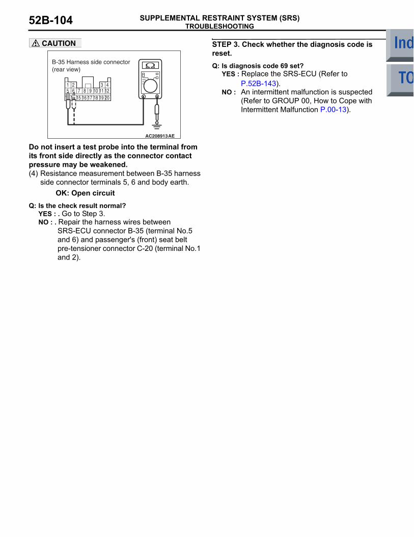
TROUBLESHOOTINGSUPPLEMENTAL RESTRAINT SYSTEM (SRS)52B-104
CAUTION
Do not insert a test probe into the terminal from its front side directly as the connector contact pressure may be weakened.(4) Resistance measurement between B-35 harness
side connector terminals 5, 6 and body earth.OK: Open circuit
Q: Is the check result normal?YES : . Go to Step 3.NO : . Repair the harness wires between
SRS-ECU connector B-35 (terminal No.5 and 6) and passenger's (front) seat belt pre-tensioner connector C-20 (terminal No.1 and 2).
STEP 3. Check whether the diagnosis code is reset.Q: Is diagnosis code 69 set?
YES : Replace the SRS-ECU (Refer to P.52B-143).
NO : An intermittent malfunction is suspected (Refer to GROUP 00, How to Cope with Intermittent Malfunction P.00-13).
13 14 16 17 19 205 6 7 8 9 10 11 121 2 3 4
1815
AC208913
B-35 Harness side connector (rear view)
AE

TROUBLESHOOTINGSUPPLEMENTAL RESTRAINT SYSTEM (SRS) 52B-105
Code No.71: Side-airbag module (squib) (RH) system (short-circuited between terminals of the squib circuit)
OPERATION• The SRS-ECU judges how severe a collision is
by detecting signals from the left and right side impact sensors. If the impact is over a predeter-mined level, the SRS-ECU sends an ignition sig-nal. At this time, if the side-airbag safing G-sensor is on, the SRS side-airbag will inflate.
• The ignition signal is input to the side-airbag module to inflate the side-airbag.
DIAGNOSIS CODE SET CONDITIONSThis diagnosis code is set if one side-airbag squib (RH) wire shorted to the other. However, if no diag-nosis code resets, the SRS warning lamp will be switched off (diagnosis code will be retained).
PROBABLE CAUSES• Improper engaged connector or defective short
spring*
• Short between the side-airbag module (RH) (squib) circuit terminals
• Damaged connector(s)• Malfunction of the SRS-ECU
NOTE: *: The squib circuit connectors integrate a "short" spring (which prevents the air bag from deploying unintentionally due to static electricity by shorting the positive wire to the earth wire in the squib circuit when the connectors are disconnected). Therefore, if connector B-34 or C-25 is damaged or improperly engaged, the short spring may not be released when the connector is connected.
DIAGNOSIS PROCEDURE
STEP 1. M.U.T.-III diagnosis codeQ: Is diagnosis code 34 set?
YES : Go to Step 2.NO : Go to Step 3.
AC510242
NOTECONNECTORCOUPLED: ONCONNECTORUNCOUPLED: OFF
CONNECTORLOCKSWITCH
AIR BAG DRIVE CIRCUIT
MICRO COMPUTER
SRS-ECU
SIDE-AIRBAG MODULE (SQUIB) (RH)
Wire colour codeB : Black LG : Light greenG : Green L : Blue W : White Y : YellowSB : Sky blue BR : Brown O : Orange GR : Grey R : Red P : Pink V : Violet
CONNECTORLOCKSWITCH
Side-airbag Module (RH) (Squib) Circuit
AB

TROUBLESHOOTINGSUPPLEMENTAL RESTRAINT SYSTEM (SRS)52B-106
STEP 2. Connector lock check: SRS-ECU connector B-34 (M.U.T.-III diagnosis code)(1) Disconnect the negative battery terminal.
(2) Disconnect connectors B-34 and then reconnect them.
(3) Connect the negative battery terminal.(4) Erase the diagnosis code memory, and check the
diagnosis code.
Q: Is diagnosis code 71 out put?YES : Go to Step 4.NO : The procedure is complete. It is assumed
that diagnosis code 71 set as connector B-34 was engaged improperly.
STEP 3. Connector lock check: SRS-ECU connector B-34 and side-airbag module (RH) connector C-25 (M.U.T.-III diagnosis code)(1) Disconnect the negative battery terminal.
(2) Disconnect connectors B-34 and C-25 and then reconnect them.
(3) Connect the negative battery terminal.(4) Erase the diagnosis code memory, and check the
diagnosis code.
Q: Is diagnosis code 71 out put?YES : Go to Step 4.NO : The procedure is complete. It is assumed
that diagnosis code 71 set as connector B-34 or C-25 was engaged improperly.
STEP 4. Check the diagnosis code by connecting a dummy resistor. (M.U.T.-III diagnosis code)(1) Disconnect the negative battery terminal.
(2) Disconnect the side-airbag module (RH) connector C-25.
(3) Connect special tool dummy resistor (MB991865) to special tool resistor harness (MB991866).CAUTION
Do not insert a test probe into the terminal from its front side directly as the connector contact pressure may be weakened.(4) Insert special tool (MB991866) into the C-25
harness side connector by backprobing.(5) Connect the negative battery terminal.(6) Erase the diagnosis code memory, and check the
diagnosis code.
Q: Is diagnosis code 71 set?YES : Go to Step 5.NO : Replace the frame assembly of the front
seat (RH) (Refer to GROUP 52A, Front Seat P.52A-23).
AC206285AG
B-34 (Y)
Connector: B-34
Harness side connector (rear view)
3435363738394041422526272829303132332122 2324
AC206285AG
B-34 (Y)
Connector: B-34
Harness side connector (rear view)
3435363738394041422526272829303132332122 2324
AC401575
Connector: C-25
AB
C-25 (R)
2 1
Harness sideconnector(front view)
AC401575
Connector: C-25
AB
C-25 (R)
2 1
Harness sideconnector(front view)
AC006042CL
MB991866(Resistor harness)
C-25 Harness sideconnector
C-25 Side-airbagmodule (RH) connector
MB991865 (Dummyresistor: 3 Ω)

TROUBLESHOOTINGSUPPLEMENTAL RESTRAINT SYSTEM (SRS) 52B-107
STEP 5. Resistance measurement at the SRS-ECU connector B-34
(1) Disconnect SRS-ECU connector B-34.DANGER
To prevents the air bag from deploying unin-tentionally, disconnect the side-airbag mod-ule (RH) connector C-25 to short the squib circuit.(2) Disconnect side-airbag module connector C-25.
CAUTION
Insert an insulator such as a cable tie to a depth of 4mm or more, otherwise the short spring will not be released.(3) Insert a cable tie [3 mm wide, 0.5 mm thick]
between terminals 23, 24 and the short spring to release the short spring.
(4) Measure at the wiring harness side.CAUTION
Do not insert a test probe into the terminal from its front side directly as the connector contact pressure may be weakened.(5) Resistance measurement between B-34 harness
side connector terminals 23 and 24.OK: Open circuit
Q: Is the check result normal?YES : Go to Step 6.NO : Repair the harness wires between
SRS-ECU connector B-34 (terminal No.23 and 24) and side-airbag module (RH) connector C-25 (terminal No.1 and 2).
STEP 6. Check whether the diagnosis code is reset.Q: Is diagnosis code 71 set?
YES : Replace the SRS-ECU (Refer to P.52B-143).
NO : An intermittent malfunction is suspected (Refer to GROUP 00, How to Cope with Intermittent Malfunction P.00-13).
AC206285AG
B-34 (Y)
Connector: B-34
Harness side connector (rear view)
3435363738394041422526272829303132332122 2324
AC401575
Connector: C-25
AB
C-25 (R)
2 1
Harness sideconnector(front view)
AC100396
SectionA - A
B-34 Harness side connector(front view)
Cable tie
Short spring4 mm or more
Terminal
A
AW
A
34 35 36 37 38 39 40 41 4225 26 27 28 29 30 31 32 3321 22 23 24
AC100764
B-34 Harness side connector(rear view)
AR

TROUBLESHOOTINGSUPPLEMENTAL RESTRAINT SYSTEM (SRS)52B-108
Code No.72: Side-airbag module (squib) (RH) system (open-circuited in the squib circuit)
OPERATION• The SRS-ECU judges how severe a collision is
by detecting signals from the left and right side impact sensors. If the impact is over a predeter-mined level, the SRS-ECU sends an ignition sig-nal. At this time, if the side-airbag safing G-sensor is on, the SRS side-airbag will inflate.
• The ignition signal is input to the side-airbag module to inflate the side-airbag.
DIAGNOSIS CODE SET CONDITIONSThis diagnosis code is set if the side-airbag squib (RH) wire(s) are open-circuited. However, if no diag-nosis code resets, the SRS warning lamp will be switched off (diagnosis code will be retained).
PROBABLE CAUSES• Open circuit in the side-airbag module (RH)
(squib) circuit• Improper connector contact• Malfunction of the SRS-ECU
AC510242
NOTECONNECTORCOUPLED: ONCONNECTORUNCOUPLED: OFF
CONNECTORLOCKSWITCH
AIR BAG DRIVE CIRCUIT
MICRO COMPUTER
SRS-ECU
SIDE-AIRBAG MODULE (SQUIB) (RH)
Wire colour codeB : Black LG : Light greenG : Green L : Blue W : White Y : YellowSB : Sky blue BR : Brown O : Orange GR : Grey R : Red P : Pink V : Violet
CONNECTORLOCKSWITCH
Side-airbag Module (RH) (Squib) Circuit
AB
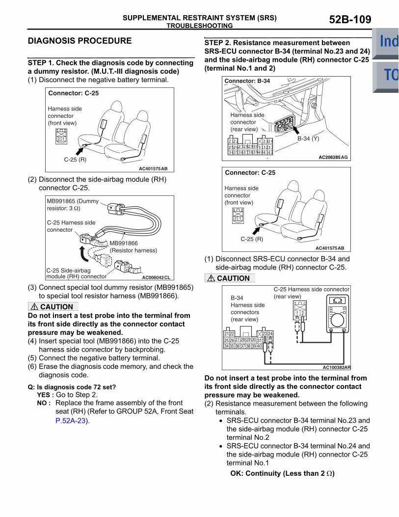
TROUBLESHOOTINGSUPPLEMENTAL RESTRAINT SYSTEM (SRS) 52B-109
DIAGNOSIS PROCEDURE
STEP 1. Check the diagnosis code by connecting a dummy resistor. (M.U.T.-III diagnosis code)(1) Disconnect the negative battery terminal.
(2) Disconnect the side-airbag module (RH) connector C-25.
(3) Connect special tool dummy resistor (MB991865) to special tool resistor harness (MB991866).CAUTION
Do not insert a test probe into the terminal from its front side directly as the connector contact pressure may be weakened.(4) Insert special tool (MB991866) into the C-25
harness side connector by backprobing.(5) Connect the negative battery terminal.(6) Erase the diagnosis code memory, and check the
diagnosis code.
Q: Is diagnosis code 72 set?YES : Go to Step 2.NO : Replace the frame assembly of the front
seat (RH) (Refer to GROUP 52A, Front Seat P.52A-23).
STEP 2. Resistance measurement between SRS-ECU connector B-34 (terminal No.23 and 24) and the side-airbag module (RH) connector C-25 (terminal No.1 and 2)
(1) Disconnect SRS-ECU connector B-34 and side-airbag module (RH) connector C-25.CAUTION
Do not insert a test probe into the terminal from its front side directly as the connector contact pressure may be weakened.(2) Resistance measurement between the following
terminals. • SRS-ECU connector B-34 terminal No.23 and
the side-airbag module (RH) connector C-25 terminal No.2
• SRS-ECU connector B-34 terminal No.24 and the side-airbag module (RH) connector C-25 terminal No.1OK: Continuity (Less than 2 Ω)
AC401575
Connector: C-25
AB
C-25 (R)
2 1
Harness sideconnector(front view)
AC006042CL
MB991866(Resistor harness)
C-25 Harness sideconnector
C-25 Side-airbagmodule (RH) connector
MB991865 (Dummyresistor: 3 Ω)
AC206285AG
B-34 (Y)
Connector: B-34
Harness side connector (rear view)
3435363738394041422526272829303132332122 2324
AC401575
Connector: C-25
AB
C-25 (R)
2 1
Harness sideconnector(front view)
34 35 36 37 38 39 40 41 4225 26 27 28 29 30 31 32 3321 22 23 24
1 2
AC100382
B-34 Harness side connectors(rear view)
C-25 Harness side connector(rear view)
AR

TROUBLESHOOTINGSUPPLEMENTAL RESTRAINT SYSTEM (SRS)52B-110
Q: Are the check results normal?YES : Go to Step 3.NO : Repair the harness wires between
SRS-ECU connector B-34 (terminal No.23 and 24) and side-airbag module (RH) connector C-25 (terminal No.1 and 2).
STEP 3. Check whether the diagnosis code is reset.Q: Is diagnosis code 72 set?
YES : Replace the SRS-ECU (Refer to P.52B-143).
NO : An intermittent malfunction is suspected (Refer to GROUP 00, How to Cope with Intermittent Malfunction P.00-13).
Code No.75: Side-airbag module (squib) (RH) system (short-circuited to the power supply)
OPERATION• The SRS-ECU judges how severe a collision is
by detecting signals from the left and right side impact sensors. If the impact is over a predeter-mined level, the SRS-ECU sends an ignition sig-nal. At this time, if the side-airbag safing G-sensor is on, the SRS side-airbag will inflate.
• The ignition signal is input to the side-airbag module to inflate the side-airbag.
DIAGNOSIS CODE SET CONDITIONSThis diagnosis code is set if the side-airbag squib (RH) wire(s) are short-circuited to the power supply.
PROBABLE CAUSES• Damaged wiring harnesses or connectors• Short to the power supply in the side-airbag mod-
ule (RH) (squib) harness• Malfunction of the SRS-ECU
AC510242
NOTECONNECTORCOUPLED: ONCONNECTORUNCOUPLED: OFF
CONNECTORLOCKSWITCH
AIR BAG DRIVE CIRCUIT
MICRO COMPUTER
SRS-ECU
SIDE-AIRBAG MODULE (SQUIB) (RH)
Wire colour codeB : Black LG : Light greenG : Green L : Blue W : White Y : YellowSB : Sky blue BR : Brown O : Orange GR : Grey R : Red P : Pink V : Violet
CONNECTORLOCKSWITCH
Side-airbag Module (RH) (Squib) Circuit
AB

TROUBLESHOOTINGSUPPLEMENTAL RESTRAINT SYSTEM (SRS) 52B-111
DIAGNOSIS PROCEDURE
STEP 1. Check the diagnosis code by connecting a dummy resistor. (M.U.T.-III diagnosis code)(1) Disconnect the negative battery terminal.
(2) Disconnect the side-airbag module (RH) connector C-25.
(3) Connect special tool dummy resistor (MB991865) to special tool resistor harness (MB991866).CAUTION
Do not insert a test probe into the terminal from its front side directly as the connector contact pressure may be weakened.(4) Insert special tool (MB991866) into the C-25
harness side connector by backprobing.(5) Connect the negative battery terminal.(6) Erase the diagnosis code memory, and check the
diagnosis code.
Q: Is diagnosis code 75 set?YES : Go to Step 2.NO : Replace the frame assembly of the front
seat (RH) (Refer to GROUP 52A, Front Seat P.52A-23).
STEP 2. Voltage measurement at the SRS-ECU connector B-34.
(1) Disconnect SRS-ECU connector B-34.DANGER
To prevents the air bag from deploying unin-tentionally, disconnect the side-airbag mod-ule (RH) connector C-25 to short the squib circuit.(2) Disconnect side-airbag module (RH) connector
C-25.(3) Connect the negative battery terminal.(4) Turn the ignition switch to the "ON" position.
CAUTION
Do not insert a test probe into the terminal from its front side directly as the connector contact pressure may be weakened.(5) Voltage measurement between B-34 harness
side connector terminals 23 and 24 and body earth.
OK: 0 V
AC401575
Connector: C-25
AB
C-25 (R)
2 1
Harness sideconnector(front view)
AC006042CL
MB991866(Resistor harness)
C-25 Harness sideconnector
C-25 Side-airbagmodule (RH) connector
MB991865 (Dummyresistor: 3 Ω)
AC206285AG
B-34 (Y)
Connector: B-34
Harness side connector (rear view)
3435363738394041422526272829303132332122 2324
AC401575
Connector: C-25
AB
C-25 (R)
2 1
Harness sideconnector(front view)
34 35 36 37 38 39 40 41 4225 26 27 28 29 30 31 32 3321 22 23 24
AC208819
B-34 Harness side connector(rear view)
AE

TROUBLESHOOTINGSUPPLEMENTAL RESTRAINT SYSTEM (SRS)52B-112
Q: Is the check result normal?YES : Go to Step 3.NO : Repair the harness wires between
SRS-ECU connector B-34 (terminal No.23 and 24) and side-airbag module (RH) connector C-25 (terminal No.1 and 2).
STEP 3. Check whether the diagnosis code is reset.Q: Is diagnosis code 75 set?
YES : Replace the SRS-ECU (Refer to P.52B-143).
NO : An intermittent malfunction is suspected (Refer to GROUP 00, How to Cope with Intermittent Malfunction P.00-13).
Code No.76: Side-airbag module (squib) (RH) system (short-circuited to the earth)
OPERATION• The SRS-ECU judges how severe a collision is
by detecting signals from the left and right side impact sensors. If the impact is over a predeter-mined level, the SRS-ECU sends an ignition sig-nal. At this time, if the side-airbag safing G-sensor is on, the SRS side-airbag will inflate.
• The ignition signal is input to the side-airbag module to inflate the side-airbag.
DIAGNOSIS CODE SET CONDITIONSThis diagnosis code is set if the side-airbag squib (RH) wire(s) are short-circuited to the earth.
PROBABLE CAUSES• Damaged wiring harnesses or connectors• Short to earth in the side-airbag module (RH)
(squib) harness• Malfunction of the SRS-ECU
AC510242
NOTECONNECTORCOUPLED: ONCONNECTORUNCOUPLED: OFF
CONNECTORLOCKSWITCH
AIR BAG DRIVE CIRCUIT
MICRO COMPUTER
SRS-ECU
SIDE-AIRBAG MODULE (SQUIB) (RH)
Wire colour codeB : Black LG : Light greenG : Green L : Blue W : White Y : YellowSB : Sky blue BR : Brown O : Orange GR : Grey R : Red P : Pink V : Violet
CONNECTORLOCKSWITCH
Side-airbag Module (RH) (Squib) Circuit
AB

TROUBLESHOOTINGSUPPLEMENTAL RESTRAINT SYSTEM (SRS) 52B-113
DIAGNOSIS PROCEDURE
STEP 1. Check the diagnosis code by connecting a dummy resistor. (M.U.T.-III diagnosis code)(1) Disconnect the negative battery terminal.
(2) Disconnect the side-airbag module (RH) connector C-25.
(3) Connect special tool dummy resistor (MB991865) to special tool resistor harness (MB991866).CAUTION
Do not insert a test probe into the terminal from its front side directly as the connector contact pressure may be weakened.(4) Insert special tool (MB991866) into the C-25
harness side connector by backprobing.(5) Connect the negative battery terminal.(6) Erase the diagnosis code memory, and check the
diagnosis code.
Q: Is diagnosis code 76 set?YES : Go to Step 2.NO : Replace the frame assembly of the front
seat (RH) (Refer to GROUP 52A, Front Seat P.52A-23).
STEP 2. Resistance measurement at the SRS-ECU connector B-34
(1) Disconnect SRS-ECU connector B-34.DANGER
To prevents the air bag from deploying unin-tentionally, disconnect the side-airbag mod-ule (RH) connector C-25 to short the squib circuit.(2) Disconnect side-airbag module (RH) connector
C-25.CAUTION
Do not insert a test probe into the terminal from its front side directly as the connector contact pressure may be weakened.(3) Resistance measurement between B-34 harness
side connector terminals 23, 24 and body earth.OK: Open circuit
AC401575
Connector: C-25
AB
C-25 (R)
2 1
Harness sideconnector(front view)
AC006042CL
MB991866(Resistor harness)
C-25 Harness sideconnector
C-25 Side-airbagmodule (RH) connector
MB991865 (Dummyresistor: 3 Ω)
AC206285AG
B-34 (Y)
Connector: B-34
Harness side connector (rear view)
3435363738394041422526272829303132332122 2324
AC401575
Connector: C-25
AB
C-25 (R)
2 1
Harness sideconnector(front view)
34 35 36 37 38 39 40 41 4225 26 27 28 29 30 31 32 3321 22 23 24
AC100384
B-34 Harness side connector(rear view)
AR

TROUBLESHOOTINGSUPPLEMENTAL RESTRAINT SYSTEM (SRS)52B-114
Q: Is the check result normal?YES : Go to Step 3.NO : Repair the harness wires between
SRS-ECU connector B-34 (terminal No.23 and 24) and side-airbag module (RH) connector C-25 (terminal No.1 and 2).
STEP 3. Check whether the diagnosis code is reset.Q: Is diagnosis code 76 set?
YES : Replace the SRS-ECU (Refer to P.52B-143).
NO : An intermittent malfunction is suspected (Refer to GROUP 00, How to Cope with Intermittent Malfunction P.00-13).
Code No.79: Side impact sensor (LH) communication error Code No.93: Side impact sensor (LH) communication impossible
OPERATIONThe side impact sensor (front) includes an analogue G-sensor and CPU, etc. The CPU monitors the ana-logue G-sensor output signal. If the CPU judges that the side-airbags should be deployed, it sends a fire signal to the SRS-ECU to deploy the side-airbags. Besides that, the CPU diagnoses the internal compo-nents of the side impact sensor. If a malfunction occurs, it requests the SRS-ECU to set a diagnosis code.
DIAGNOSIS CODE SET CONDITIONSThese diagnosis codes are set if communication between the side impact sensor (LH) and the SRS-ECU is not possible or communication is faulty.
PROBABLE CAUSES• Damaged wiring harnesses or connectors• Malfunction of the side impact sensor (LH)• Malfunction of the SRS-ECU
AC510245
SRS-ECU
CONSTANTVOLTAGE CIRCUIT
ANALOGUEG SENSOREEP ROM
SIDE IMPACTSENSOR (LH)
MICRO COMPUTER
INTERFACE CIRCUIT
CPU
Wire colour codeB : Black LG : Light green G : Green L : Blue W : White Y : Yellow SB : Sky blueBR : Brown O : Orange GR : Grey R : Red P : Pink V : Violet
Side Impact Sensor (LH) Power Supply Circuit
AB

TROUBLESHOOTINGSUPPLEMENTAL RESTRAINT SYSTEM (SRS) 52B-115
DIAGNOSIS PROCEDURE
STEP 1. Check the side impact sensor (LH). (M.U.T.-III diagnosis code)(1) Disconnect the negative battery terminal.(2) Temporarily replace the side impact sensor (LH)
with the side impact sensor (RH).(3) Connect the negative battery terminal.(4) Erase diagnosis code memory, and check the
diagnosis code.
Q: Is diagnosis code 89 or 96 set?YES : Replace the side impact sensor (LH) with a
new one (Refer to P.52B-157).NO : Go to Step 2.
STEP 2. Check the harness wires for open circuit or short circuit between SRS-ECU connector B-34 (terminal No.34 and 36) and side impact sensor (LH) (front) connector C-21 (terminal No.1 and 2).
Q: Is the check result normal?YES : Go to Step 3.NO : Repair the harness wires between
SRS-ECU connector B-34 (terminal No.34 and 36) and side impact sensor (LH) connector C-21 (terminal No.1 and 2).
STEP 3. Check whether the diagnosis code is reset.Q: Is diagnosis code 79 or 93 set?
YES : Replace the SRS-ECU (Refer to P.52B-143).
NO : An intermittent malfunction is suspected (Refer to GROUP 00, How to Cope with Intermittent Malfunction P.00-13).
AC206285AG
B-34 (Y)
Connector: B-34
Harness side connector (rear view)
3435363738394041422526272829303132332122 2324
AC401059
Connector: C-21
AFC-21 (Y)
Harness side(front view)

TROUBLESHOOTINGSUPPLEMENTAL RESTRAINT SYSTEM (SRS)52B-116
Code No.81: Side-airbag module (squib) (LH) system (short-circuited between terminals of the squib circuit)
OPERATION• The SRS-ECU judges how severe a collision is
by detecting signals from the left and right side impact sensors. If the impact is over a predeter-mined level, the SRS-ECU sends an ignition sig-nal. At this time, if the side-airbag safing G-sensor is on, the SRS side-airbag will inflate.
• The ignition signal is input to the side-airbag module to inflate the side-airbag.
DIAGNOSIS CODE SET CONDITIONSThis diagnosis code is set if one side-airbag squib (LH) wire shorted to the other. However, if no diagno-sis code resets, the SRS warning lamp will be switched off (diagnosis code will be retained).
PROBABLE CAUSES• Improper engaged connector or defective short
spring*
• Short circuit between the side-airbag module (LH) (squib) circuit terminals
• Damaged connector(s)• Malfunction of the SRS-ECU
NOTE: *: The squib circuit connectors integrate a "short" spring (which prevents the air bag from deploying unintentionally due to static electricity by shorting the positive wire to the earth wire in the squib circuit when the connectors are disconnected). (Refer to P.52B-3). Therefore, if connector B-34 or C-23 is damaged or improperly engaged, the short spring may not be released when the connector is connected.
DIAGNOSIS PROCEDURE
STEP 1. M.U.T.-III diagnosis codeQ: Is diagnosis code 34 set?
YES : Go to Step 2.NO : Go to Step 3.
AC510246
AIR BAG DRIVE CIRCUIT
MICRO COMPUTER
SRS-ECU
SIDE-AIRBAGMODULE (SQUIB)(LH)
Wire colour codeB : Black LG : Light greenG : Green L : Blue W : White Y : YellowSB : Sky blue BR : Brown O : Orange GR : Grey R : Red P : Pink V : Violet
NOTECONNECTORCOUPLED: ONCONNECTORUNCOUPLED: OFF
CONNECTORLOCKSWITCH
CONNECTORLOCKSWITCH
Side-airbag Module (LH) (Squib) Circuit
AB

TROUBLESHOOTINGSUPPLEMENTAL RESTRAINT SYSTEM (SRS) 52B-117
STEP 2. Connector lock check: SRS-ECU connector B-34 (M.U.T.-III diagnosis code)(1) Disconnect the negative battery terminal.
(2) Disconnect connectors B-34 and then reconnect them.
(3) Connect the negative battery terminal.(4) Erase the diagnosis code memory, and check the
diagnosis code.
Q: Is diagnosis code 81 out put?YES : Go to Step 3.NO : The procedure is complete. It is assumed
that diagnosis code 81 set as connector B-34 was engaged improperly.
STEP 3. Connector lock check: SRS-ECU connector B-34 and side-airbag module (LH) connector C-23 (M.U.T.-III diagnosis code)(1) Disconnect the negative battery terminal.
(2) Disconnect connectors B-34 and C-23 and then reconnect them.
(3) Connect the negative battery terminal.(4) Erase the diagnosis code memory, and check the
diagnosis code.
Q: Is diagnosis code 81 out put?YES : Go to Step 4.NO : The procedure is complete. It is assumed
that diagnosis code 81 set as connector B-34 or C-23 was engaged improperly.
STEP 4. Check the diagnosis code by connecting a dummy resistor. (M.U.T.-III diagnosis code)(1) Disconnect the negative battery terminal.
(2) Disconnect the side-airbag module (LH) connector C-23.
(3) Connect special tool dummy resistor (MB991865) to special tool resistor harness (MB991866).CAUTION
Do not insert a test probe into the terminal from its front side directly as the connector contact pressure may be weakened.(4) Insert special tool (MB991866) into the C-23
harness side connector by backprobing.(5) Connect the negative battery terminal.(6) Erase diagnosis code memory, and check the
diagnosis code.
Q: Is diagnosis code 81 set?YES : Go to Step 5.NO : Replace the frame assembly of the front
seat (LH) (Refer to GROUP 52A, Front Seat P.52A-23).
AC206285AG
B-34 (Y)
Connector: B-34
Harness side connector (rear view)
3435363738394041422526272829303132332122 2324
AC206285AG
B-34 (Y)
Connector: B-34
Harness side connector (rear view)
3435363738394041422526272829303132332122 2324
AC401575
Connector: C-23
ACC-23 (R)
2 1
Harness sideconnector(front view)
AC401575
Connector: C-23
ACC-23 (R)
2 1
Harness sideconnector(front view)
AC006042CM
MB991866(Resistor harness)
C-23 Intermediate harness sideconnector
MB991865 (Dummyresistor: 3 Ω)
C-23 Side-airbagmodule (LH) connector
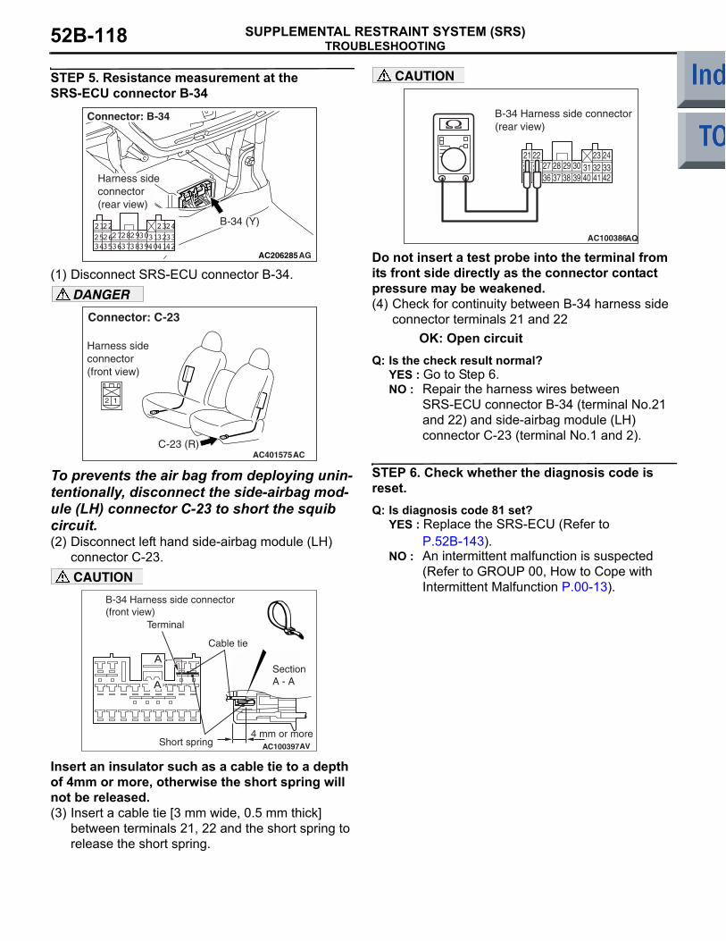
TROUBLESHOOTINGSUPPLEMENTAL RESTRAINT SYSTEM (SRS)52B-118
STEP 5. Resistance measurement at the SRS-ECU connector B-34
(1) Disconnect SRS-ECU connector B-34.DANGER
To prevents the air bag from deploying unin-tentionally, disconnect the side-airbag mod-ule (LH) connector C-23 to short the squib circuit.(2) Disconnect left hand side-airbag module (LH)
connector C-23.CAUTION
Insert an insulator such as a cable tie to a depth of 4mm or more, otherwise the short spring will not be released.(3) Insert a cable tie [3 mm wide, 0.5 mm thick]
between terminals 21, 22 and the short spring to release the short spring.
CAUTION
Do not insert a test probe into the terminal from its front side directly as the connector contact pressure may be weakened.(4) Check for continuity between B-34 harness side
connector terminals 21 and 22OK: Open circuit
Q: Is the check result normal? YES : Go to Step 6. NO : Repair the harness wires between
SRS-ECU connector B-34 (terminal No.21 and 22) and side-airbag module (LH) connector C-23 (terminal No.1 and 2).
STEP 6. Check whether the diagnosis code is reset.Q: Is diagnosis code 81 set?
YES : Replace the SRS-ECU (Refer to P.52B-143).
NO : An intermittent malfunction is suspected (Refer to GROUP 00, How to Cope with Intermittent Malfunction P.00-13).
AC206285AG
B-34 (Y)
Connector: B-34
Harness side connector (rear view)
3435363738394041422526272829303132332122 2324
AC401575
Connector: C-23
ACC-23 (R)
2 1
Harness sideconnector(front view)
AC100397
SectionA - A
B-34 Harness side connector(front view)
Cable tie
Short spring4 mm or more
Terminal
A
AV
A
34 35 36 37 38 39 40 41 4225 26 27 28 29 30 31 32 3321 22 23 24
AC100386
B-34 Harness side connector(rear view)
AQ

TROUBLESHOOTINGSUPPLEMENTAL RESTRAINT SYSTEM (SRS) 52B-119
Code No.82: Side-airbag module (squib) (LH) system (open-circuited in the squib circuit)
OPERATION• The SRS-ECU judges how severe a collision is
by detecting signals from the left and right side impact sensors. If the impact is over a predeter-mined level, the SRS-ECU sends an ignition sig-nal. At this time, if the side-airbag safing G-sensor is on, the SRS side-airbag will inflate.
• The ignition signal is input to the side-airbag module to inflate the side-airbag.
DIAGNOSIS CODE SET CONDITIONSThis diagnosis code is set if the side-airbag squib (LH) wire(s) are open-circuited. However, if no diag-nosis code resets, the SRS warning lamp will be switched off (diagnosis code will be retained).
PROBABLE CAUSES• Open circuit in the side-airbag module (squib)
(LH) circuit• Improper connector contact• Malfunction of the SRS-ECU
AC510246
AIR BAG DRIVE CIRCUIT
MICRO COMPUTER
SRS-ECU
SIDE-AIRBAGMODULE (SQUIB)(LH)
Wire colour codeB : Black LG : Light greenG : Green L : Blue W : White Y : YellowSB : Sky blue BR : Brown O : Orange GR : Grey R : Red P : Pink V : Violet
NOTECONNECTORCOUPLED: ONCONNECTORUNCOUPLED: OFF
CONNECTORLOCKSWITCH
CONNECTORLOCKSWITCH
Side-airbag Module (LH) (Squib) Circuit
AB

TROUBLESHOOTINGSUPPLEMENTAL RESTRAINT SYSTEM (SRS)52B-120
DIAGNOSIS PROCEDURE
STEP 1. Check the diagnosis code by connecting a dummy resistor. (M.U.T.-III diagnosis code)(1) Disconnect the negative battery terminal.
(2) Disconnect the side-airbag module (LH) connector C-23.
(3) Connect special tool dummy resistor (MB991865) to special tool resistor harness (MB991866).CAUTION
Do not insert a test probe into the terminal from its front side directly as the connector contact pressure may be weakened.(4) Insert special tool (MB991866) into the C-23
harness side connector by backprobing.(5) Connect the negative battery terminal.(6) Erase diagnosis code memory, and then check
the diagnosis code.
Q: Is diagnosis code 82 set?YES : Go to Step 2.NO : Replace the frame assembly of the front
seat (LH) (Refer to GROUP 52A, Front Seat P.52A-23).
STEP 2. Resistance measurement between the SRS-ECU connector B-34 (terminal No.21 and 22) and the side-airbag module (LH) connector C-23 (terminal No.1 and 2)
(1) Disconnect SRS-ECU connector B-34.
(2) Disconnect side-airbag module (LH) connector C-23.CAUTION
Do not insert a test probe into the terminal from its front side directly as the connector contact pressure may be weakened.(3) Resistance measurement between the following
terminals. • SRS-ECU connector B-34 (terminal No.21)
and the side-airbag module (LH) connector C-23 (terminal No.1)
• SRS-ECU connector B-34 (terminal No.22) and the side-airbag module (LH) connector C-23 (terminal No.2)OK: Continuity (Less than 2 Ω)
AC401575
Connector: C-23
ACC-23 (R)
2 1
Harness sideconnector(front view)
AC006042CM
MB991866(Resistor harness)
C-23 Intermediate harness sideconnector
MB991865 (Dummyresistor: 3 Ω)
C-23 Side-airbagmodule (LH) connector
AC206285AG
B-34 (Y)
Connector: B-34
Harness side connector (rear view)
3435363738394041422526272829303132332122 2324
AC401575
Connector: C-23
ACC-23 (R)
2 1
Harness sideconnector(front view)
3435363738394041422526272829303132332122 2324
1 2
AC100387
B-34 Harnessside connector(rear view)
AL
C-23 Harness side connector (rear view)

TROUBLESHOOTINGSUPPLEMENTAL RESTRAINT SYSTEM (SRS) 52B-121
Q: Are the check results normal?YES : Go to Step 3. NO : Repair the harness wires between
SRS-ECU connector B-34 (terminal No.21 and 22) and side-airbag module (LH) connector C-23 (terminal No.1 and 2).
STEP 3. Check whether the diagnosis code is reset.Q: Is diagnosis code 82 set?
YES : Replace the SRS-ECU (Refer to P.52B-143).
NO : An intermittent malfunction is suspected (Refer to GROUP 00, How to Cope with Intermittent Malfunction P.00-13).
Code No.85: Side-airbag module (squib) (LH) system (short-circuited to the power supply)
OPERATION• The SRS-ECU judges how severe a collision is
by detecting signals from the left and right side impact sensors. If the impact is over a predeter-mined level, the SRS-ECU sends an ignition sig-nal. At this time, if the side-airbag safing G-sensor is on, the SRS side-airbag will inflate.
• The ignition signal is input to the side-airbag module to inflate the side-airbag.
DIAGNOSIS CODE SET CONDITIONSThis diagnosis code is set if the side-airbag squib (LH) wire(s) are short-circuited to the power supply.
PROBABLE CAUSES• Damaged wiring harnesses or connectors• Short to the power supply in the side-airbag mod-
ule (LH) (squib) harness• Malfunction of the SRS-ECU
AC510246
AIR BAG DRIVE CIRCUIT
MICRO COMPUTER
SRS-ECU
SIDE-AIRBAGMODULE (SQUIB)(LH)
Wire colour codeB : Black LG : Light greenG : Green L : Blue W : White Y : YellowSB : Sky blue BR : Brown O : Orange GR : Grey R : Red P : Pink V : Violet
NOTECONNECTORCOUPLED: ONCONNECTORUNCOUPLED: OFF
CONNECTORLOCKSWITCH
CONNECTORLOCKSWITCH
Side-airbag Module (LH) (Squib) Circuit
AB
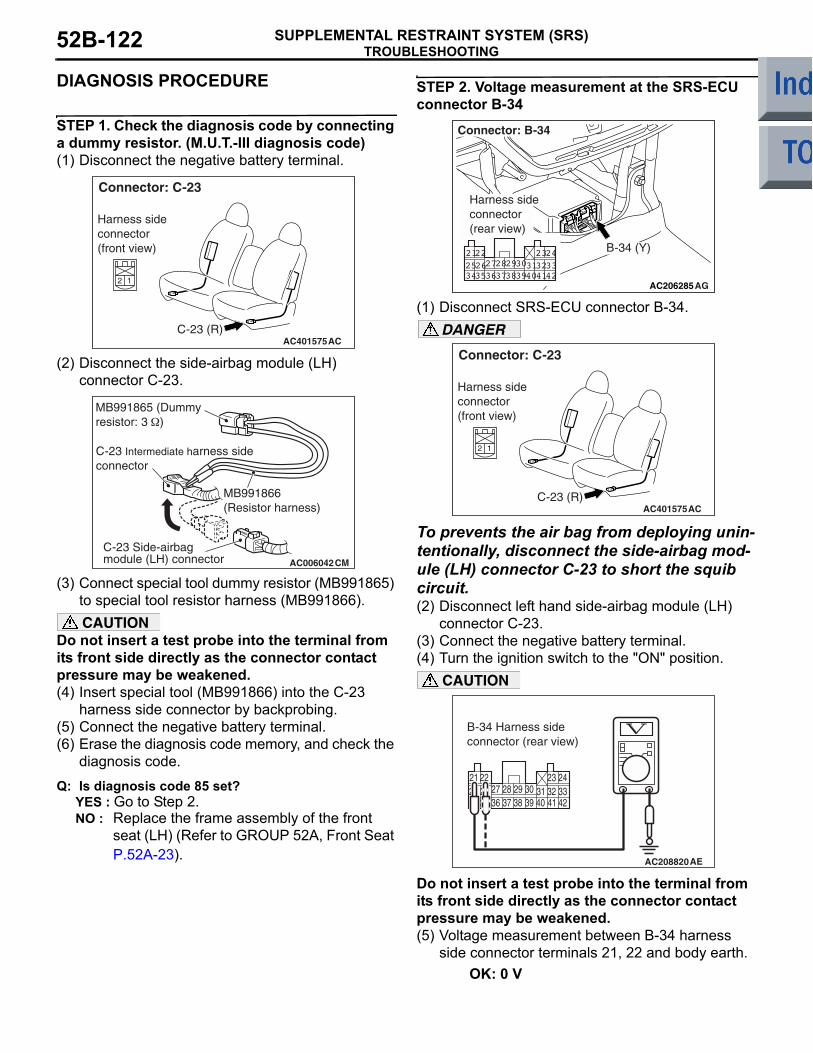
TROUBLESHOOTINGSUPPLEMENTAL RESTRAINT SYSTEM (SRS)52B-122
DIAGNOSIS PROCEDURE
STEP 1. Check the diagnosis code by connecting a dummy resistor. (M.U.T.-III diagnosis code)(1) Disconnect the negative battery terminal.
(2) Disconnect the side-airbag module (LH) connector C-23.
(3) Connect special tool dummy resistor (MB991865) to special tool resistor harness (MB991866).CAUTION
Do not insert a test probe into the terminal from its front side directly as the connector contact pressure may be weakened.(4) Insert special tool (MB991866) into the C-23
harness side connector by backprobing.(5) Connect the negative battery terminal.(6) Erase the diagnosis code memory, and check the
diagnosis code.
Q: Is diagnosis code 85 set?YES : Go to Step 2.NO : Replace the frame assembly of the front
seat (LH) (Refer to GROUP 52A, Front Seat P.52A-23).
STEP 2. Voltage measurement at the SRS-ECU connector B-34
(1) Disconnect SRS-ECU connector B-34.DANGER
To prevents the air bag from deploying unin-tentionally, disconnect the side-airbag mod-ule (LH) connector C-23 to short the squib circuit.(2) Disconnect left hand side-airbag module (LH)
connector C-23.(3) Connect the negative battery terminal.(4) Turn the ignition switch to the "ON" position.
CAUTION
Do not insert a test probe into the terminal from its front side directly as the connector contact pressure may be weakened.(5) Voltage measurement between B-34 harness
side connector terminals 21, 22 and body earth.OK: 0 V
AC401575
Connector: C-23
ACC-23 (R)
2 1
Harness sideconnector(front view)
AC006042CM
MB991866(Resistor harness)
C-23 Intermediate harness sideconnector
MB991865 (Dummyresistor: 3 Ω)
C-23 Side-airbagmodule (LH) connector
AC206285AG
B-34 (Y)
Connector: B-34
Harness side connector (rear view)
3435363738394041422526272829303132332122 2324
AC401575
Connector: C-23
ACC-23 (R)
2 1
Harness sideconnector(front view)
34 35 36 37 38 39 40 41 4225 26 27 28 29 30 31 32 3321 22 23 24
AC208820
B-34 Harness side connector (rear view)
AE

TROUBLESHOOTINGSUPPLEMENTAL RESTRAINT SYSTEM (SRS) 52B-123
Q: Is the check result normal? YES : Go to Step 3.NO : Repair the harness wires between
SRS-ECU connector B-34 (terminal No.21 and 22) and side-airbag module (LH) connector C-23 (terminal No.1 and 2).
STEP 3. Check whether the diagnosis code is reset.Q: Is diagnosis code 85 set?
YES : Replace the SRS-ECU (Refer to P.52B-143).
NO : An intermittent malfunction is suspected (Refer to GROUP 00, How to Cope with Intermittent Malfunction P.00-13).
Code No.86: Side-airbag module (squib) (LH) system (short-circuited to the earth)
OPERATION• The SRS-ECU judges how severe a collision is
by detecting signals from the left and right side impact sensors. If the impact is over a predeter-mined level, the SRS-ECU sends an ignition sig-nal. At this time, if the side-airbag safing G-sensor is on, the SRS side-airbag will inflate.
• The ignition signal is input to the side-airbag module to inflate the side-airbag.
DIAGNOSIS CODE SET CONDITIONSThis diagnosis code is set if the side-airbag squib (LH) wire(s) are short-circuited to the earth.
PROBABLE CAUSES• Damaged wiring harnesses or connectors• Short to earth in the left hand side-airbag module
(squib) harness• Malfunction of the SRS-ECU
AC510246
AIR BAG DRIVE CIRCUIT
MICRO COMPUTER
SRS-ECU
SIDE-AIRBAGMODULE (SQUIB)(LH)
Wire colour codeB : Black LG : Light greenG : Green L : Blue W : White Y : YellowSB : Sky blue BR : Brown O : Orange GR : Grey R : Red P : Pink V : Violet
NOTECONNECTORCOUPLED: ONCONNECTORUNCOUPLED: OFF
CONNECTORLOCKSWITCH
CONNECTORLOCKSWITCH
Side-airbag Module (LH) (Squib) Circuit
AB

TROUBLESHOOTINGSUPPLEMENTAL RESTRAINT SYSTEM (SRS)52B-124
DIAGNOSIS PROCEDURE
STEP 1. Check the diagnosis code by connecting a dummy resistor. (M.U.T.-III diagnosis code)(1) Disconnect the negative battery terminal.
(2) Disconnect the side-airbag module (LH) connector C-23.
(3) Connect special tool dummy resistor (MB991865) to special tool resistor harness (MB991866).CAUTION
Do not insert a test probe into the terminal from its front side directly as the connector contact pressure may be weakened.(4) Insert special tool (MB991866) into the C-23
harness side connector by backprobing.(5) Connect the negative battery terminal.(6) Erase the diagnosis code memory, and check the
diagnosis code.
Q: Is diagnosis code 86 set?YES : Go to Step 2.NO : Replace the frame assembly of the front
seat (LH) (Refer to GROUP 52A, Front Seat P.52A-23).
STEP 2. Resistance measurement at the SRS-ECU connector B-34
(1) Disconnect SRS-ECU connector B-34.
(2) Disconnect side-airbag module (LH) connector C-23.CAUTION
Do not insert a test probe into the terminal from its front side directly as the connector contact pressure may be weakened.(3) Check for continuity between B-34 harness side
connector terminals 21, 22 and body earth.OK: Open circuit
Q: Is the check result normal?YES : Go to Step 3.NO : Repair the harness wires between
SRS-ECU connector B-34 (terminal No.21 and 22) and side-airbag module (LH) connector C-23 (terminal No.1 and 2).
AC401575
Connector: C-23
ACC-23 (R)
2 1
Harness sideconnector(front view)
AC006042CM
MB991866(Resistor harness)
C-23 Intermediate harness sideconnector
MB991865 (Dummyresistor: 3 Ω)
C-23 Side-airbagmodule (LH) connector
AC206285AG
B-34 (Y)
Connector: B-34
Harness side connector (rear view)
3435363738394041422526272829303132332122 2324
AC401575
Connector: C-23
ACC-23 (R)
2 1
Harness sideconnector(front view)
34 35 36 37 38 39 40 41 4225 26 27 28 29 30 31 32 3321 22 23 24
AC100392
B-34 Harness side connector (rear view)
AR

TROUBLESHOOTINGSUPPLEMENTAL RESTRAINT SYSTEM (SRS) 52B-125
STEP 3. Check whether the diagnosis code is reset.Q: Is diagnosis code 86 set?
YES : Replace the SRS-ECU (Refer to P.52B-143).
NO : An intermittent malfunction is suspected (Refer to GROUP 00, How to Cope with Intermittent Malfunction P.00-13).
Code No.89: Side impact sensor (RH) communication error Code No.96: Side impact sensor (RH) communication impossible
OPERATIONThe side impact sensor includes an analogue G-sen-sor and CPU, etc. The CPU monitors the analogue G-sensor output signal. If the CPU judges that the side-airbags should be deployed, it sends a fire sig-nal to the SRS-ECU to deploy the side-airbags. Besides that, the CPU diagnoses the internal compo-nents of the side impact sensor. If a malfunction occurs, it requests the SRS-ECU to set a diagnosis code.
DIAGNOSIS CODE SET CONDITIONSThese diagnosis codes are set if communication between the side impact sensor (RH) and the SRS-ECU is not possible or faulty.
PROBABLE CAUSES• Damaged wiring harnesses or connectors• Malfunction of the side impact sensor (RH)• Malfunction of the SRS-ECU
AC510252
MICRO COMPUTER
INTERFACE CIRCUIT
CPU
SRS-ECU
ANALOGUEG SENSOREEP ROM
SIDE IMPACTSENSOR (RH)
CONSTANTVOLTAGE CIRCUIT
Wire colour codeB : Black LG : Light green G : Green L : Blue W : White Y : Yellow SB : Sky blueBR : Brown O : Orange GR : Grey R : Red P : Pink V : Violet
Side Impact Sensor (RH) Circuit
AB

TROUBLESHOOTINGSUPPLEMENTAL RESTRAINT SYSTEM (SRS)52B-126
DIAGNOSIS PROCEDURE
STEP 1. Check the side impact sensor (RH) (front). (M.U.T.-III diagnosis code)(1) Disconnect the negative battery terminal.(2) Temporarily replace the side impact sensor (RH)
with the side impact sensor (LH).(3) Connect the negative battery terminal.(4) Erase diagnosis code memory, and check the
diagnosis code.
Q: Is diagnosis code 79 or 93 out put?YES : Replace the side impact sensor (RH) with a
new one (Refer to P.52B-157).NO : Go to Step 2.
STEP 2. Check the harness wires for open circuit or short circuit between SRS-ECU connector B-34 (terminal No.40 and 42) and side impact sensor (RH) connector C-27 (terminal No.2 and 1).
Q: Is the check result normal? YES : Go to Step 3.NO : Repair the harness wires between
SRS-ECU connector B-34 (terminal No.40 and 42) and side impact sensor (RH) connector C-27 (terminal No.2 and 1).
STEP 3. Check whether the diagnosis code is reset.Q: Is diagnosis code 89 or 96 set?
YES : Replace the SRS-ECU (Refer to P.52B-143).
NO : An intermittent malfunction is suspected (Refer to GROUP 00, How to Cope with Intermittent Malfunction P.00-13).
AC206285AG
B-34 (Y)
Connector: B-34
Harness side connector (rear view)
3435363738394041422526272829303132332122 2324
AC401057AK
Connector: C-27
C-27 (Y)Harness side(front view)

TROUBLESHOOTINGSUPPLEMENTAL RESTRAINT SYSTEM (SRS) 52B-127
Code No.91: Side impact sensor (LH) voltage error
OPERATIONThe side impact sensor includes an analogue G-sen-sor and CPU, etc. The CPU monitors the analogue G-sensor output signal. If the CPU judges that the side-airbags should be deployed, it sends a fire sig-nal to the SRS-ECU to deploy the side-airbags. Besides that, the CPU diagnoses the internal compo-nents of the side impact sensor. If a malfunction occurs, it requests the SRS-ECU to set a diagnosis code.
DIAGNOSIS CODE SET CONDITIONSThis diagnosis code will set when the power supply voltage to the side impact sensor (LH) remains less than a predetermined value for 5 seconds. However, if the system returns to normal condition, code number 91 will be erased automatically and the SRS warning lamp will go out.
PROBABLE CAUSES• Damaged wiring harness or connectors• Malfunction of the side-airbag module (LH)• Malfunction of the SRS-ECU
AC510253
SRS-ECU
CONSTANTVOLTAGE CIRCUIT
ANALOGUEG SENSOREEP ROM
SIDE IMPACTSENSOR (LH)
MICRO COMPUTER
INTERFACE CIRCUIT
CPU
Wire colour codeB : Black LG : Light green G : Green L : Blue W : White Y : Yellow SB : Sky blueBR : Brown O : Orange GR : Grey R : Red P : Pink V : Violet
Side Impact Sensor (LH) Power Supply Circuit
AB

TROUBLESHOOTINGSUPPLEMENTAL RESTRAINT SYSTEM (SRS)52B-128
DIAGNOSIS PROCEDURE
STEP 1. Check the harness wires for open circuit or short circuit between SRS-ECU connector B-34 (terminal No.34 and 36) and side impact sensor (LH) connector C-21 (terminal No.1 and 2).
Q: Is the check result normal?YES : Go to Step 2.NO : Repair the harness wires between
SRS-ECU connector B-34 (terminal No.34 and 36) and side impact sensor (LH) connector C-21 (terminal No.1 and 2).
STEP 2. Check the side impact sensor (LH) (front). (M.U.T.-III diagnosis code)(1) Disconnect the negative battery terminal.(2) Replace the side impact sensor (LH) (front) with
the side impact sensor (RH) (front).(3) Connect the negative battery terminal.(4) Erase diagnosis code from memory, and check
the diagnosis code.
Q: Is diagnosis code 91 set?YES : Replace the SRS-ECU (Refer to
P.52B-143).NO : Replace the side impact sensor (LH) (front)
with a new one (Refer to P.52B-157). Go to Step 3 .
STEP 3. Check whether the diagnosis code is reset.Q: Is diagnosis code 91 set?
YES : Replace the SRS-ECU (Refer to P.52B-143).
NO : An intermittent malfunction is suspected (Refer to GROUP 00, How to Cope with Intermittent Malfunction P.00-13).
Code No.92: G-sensor of side impact sensor (LH) failure Code No.95: G-sensor of side impact sensor (RH) failure
DIAGNOSIS CODE SET CONDITIONSThese diagnosis codes are set if the followings are detected from the analogue G-sensor inside the side impact sensor (front) output.
• Analogue G-sensor inside the side impact sensor is not operating.
• Analogue G-sensor inside the side impact sensor characteristics are abnormal.
• Analogue G-sensor inside the side impact sensor output is abnormal.
PROBABLE CAUSEMalfunction of side impact sensor (LH) (for diagnosis code 92) and side impact sensor (RH) (for diagnosis code 95)
DIAGNOSIS PROCEDUREReplace side impact sensor (LH) (for diagnosis code 92) and side impact sensor (RH) (for diagnosis code 95). (Refer to P.52B-157).
AC206285AG
B-34 (Y)
Connector: B-34
Harness side connector (rear view)
3435363738394041422526272829303132332122 2324
AC401059
Connector: C-21
AFC-21 (Y)
Harness side(front view)

TROUBLESHOOTINGSUPPLEMENTAL RESTRAINT SYSTEM (SRS) 52B-129
Code No.94: Side impact sensor (RH) voltage error
OPERATIONThe side impact sensor includes an analogue G-sen-sor and CPU, etc. The CPU monitors the analogue G-sensor output signal. If the CPU judges that the side-airbags should be deployed, it sends a fire sig-nal to the SRS-ECU to deploy the side-airbags. Besides that, the CPU diagnoses the internal compo-nents of the side impact sensor. If a malfunction occurs, it requests the SRS-ECU to set a diagnosis code.
DIAGNOSIS CODE SET CONDITIONSThis diagnosis code is set if the power supply voltage of the side impact sensor (RH) drops below the rated value for a continuous period of 5 seconds or more. However, if the system returns to normal condition, code number 94 will be erased automatically and the SRS warning lamp will go out.
PROBABLE CAUSES• Damaged wiring harnesses or connectors• Malfunction of the side-airbag module (RH)• Malfunction of the SRS-ECU
AC510252
MICRO COMPUTER
INTERFACE CIRCUIT
CPU
SRS-ECU
ANALOGUEG SENSOREEP ROM
SIDE IMPACTSENSOR (RH)
CONSTANTVOLTAGE CIRCUIT
Wire colour codeB : Black LG : Light green G : Green L : Blue W : White Y : Yellow SB : Sky blueBR : Brown O : Orange GR : Grey R : Red P : Pink V : Violet
Side Impact Sensor (RH) Circuit
AB

TROUBLESHOOTINGSUPPLEMENTAL RESTRAINT SYSTEM (SRS)52B-130
DIAGNOSIS PROCEDURE
STEP 1. Check the harness wires for open circuit or short circuit between SRS-ECU connector B-34 (terminal No.40 and 42) and side impact sensor (RH) connector C-27 (terminal No.1 and 2).
Q: Are the harness wires between SRS-ECU connector B-34 (terminal No.40 and 42) and side impact sensor (RH) connector C-27 (terminal No.1 and 2) in good condition?YES : . Go to Step 2.NO : . Repair the harness wires between
SRS-ECU connector B-34> (terminal No.40 and 42) and side impact sensor (RH) connector C-27 (terminal No.1 and 2).
STEP 2. Check the side impact sensor (RH) (front). (M.U.T.-III diagnosis code)(1) Disconnect the negative battery terminal.(2) Replace the side impact sensor (RH) (front) with
the side impact sensor (LH) (front).(3) Connect the negative battery terminal.(4) Erase diagnosis code from memory, and check
the diagnosis code.
Q: Is diagnosis code 94 set?YES : Replace the SRS-ECU (Refer to
P.52B-143).NO : Replace the side impact sensor (LH) (front)
with a new one (Refer to P.52B-157). Go to Step 3 .
STEP 3. Check whether the diagnosis code is reset.Q: Is diagnosis code 94 set?
YES : Replace the SRS-ECU (Refer to P.52B-143).
NO : An intermittent malfunction is suspected (Refer to GROUP 00, How to Cope with Intermittent Malfunction P.00-13).
AC206285AG
B-34 (Y)
Connector: B-34
Harness side connector (rear view)
3435363738394041422526272829303132332122 2324
AC401057AK
Connector: C-27
C-27 (Y)Harness side(front view)

TROUBLESHOOTINGSUPPLEMENTAL RESTRAINT SYSTEM (SRS) 52B-131
CHECK CHART FOR TROUBLE SYMPTOMSM1524003400989
Trouble Inspection procedure No. Reference pageCommunication with M.U.T.-III is not possible (Communication with all systems is not possible).
− GROUP 13A, Troubleshooting P.13A-235GROUP 13B, Troubleshooting P.13B-242
Communication with M.U.T.-III is not possible (Communication is not possible with SRS).
1 P.52B-132
When the ignition switch is turned to the "ON" position (engine stopped), the SRS warning lamp does not illuminate.
Refer to diagnosis code No.43. P.52B-78
After the ignition switch is turned to the "ON" position, the SRS warning lamp does not go off within approximately 7 seconds.
Refer to diagnosis code No.43. P.52B-81

TROUBLESHOOTINGSUPPLEMENTAL RESTRAINT SYSTEM (SRS)52B-132
SYMPTOM PROCEDURES
INSPECTION PROCEDURE 1: Communication with M.U.T.-III is not possible (Communication is not possible with SRS).
OPERATION• The SRS-ECU is powered from the ignition
switch (IG1).• The SRS-ECU power is supplied from two cir-
cuits. Even if one circuit is shut off, the air bag can inflate.
• The SRS system diagnosis can be done by con-necting M.U.T.-III to the diagnosis connector.
COMMENTS ON TROUBLE SYMPTOMIf communication is not possible with the SRS only, the cause is probably an open circuit in the diagnosis output circuit of the SRS or in the power circuit (including earth circuit).
PROBABLE CAUSES• Damaged wiring harnesses or connectors• Malfunction of the SRS-ECU
DIAGNOSIS PROCEDURE
STEP 1. Check that the M.U.T.-III can communicate with the other systems.Q: Can the M.U.T.-III communicate with the other
systems?YES : Go to Step 2.NO : Refer to GROUP 13A, Troubleshooting
P.13A-235, GROUP 13B, Troubleshooting P.13B-242.
AC510262
IGNITIONSWITCH (IG1)
SRS-ECU
FRONT SIDE
DIAGNOSISCONNECTOR
FUSIBLELINK 6
Wire colour codeB : Black LG : Light green G : Green L : BlueW : White Y : Yellow SB : Sky blue BR : BrownO : Orange GR : Grey R : Red P : Pink V : Violet
SRS-ECU Power Supply Circuit
AB

TROUBLESHOOTINGSUPPLEMENTAL RESTRAINT SYSTEM (SRS) 52B-133
STEP 2. Resistance measurement between SRS-ECU connector B-35 (terminal No.20) and diagnosis connector B-32 (terminal No.7).(1) Disconnect the negative battery terminal.
(2) Disconnect SRS-ECU connector B-35 and diagnosis connector B-32, and measure at the wiring harness side. CAUTION
Do not insert a test probe into the terminal from of the SRS-ECU connector B-35 its front side directly as the connector contact pressure may be weakened.(3) Resistance measurement between the following
terminals. • SRS-ECU connector B-35 (terminal No.20)
and diagnosis connector B-32 (terminal No.7)OK: Continuity (Less than 2 Ω)
Q: Is the check results normal?YES : . Go to Step 3.NO : . Go to Step 5.
STEP 3. Resistance measurement the earth circuit to the SRS-ECU connector B-35.(1) Disconnect the negative battery terminal.
(2) Disconnect SRS-ECU connector B-35 and measure at the wiring harness side.CAUTION
Do not insert a test probe into the terminal from its front side directly as the connector contact pressure may be weakened.(3) Check for continuity between terminal 19 and
body earth.OK: Continuity (Less than 2 Ω)
Q: Is the check result normal?YES : Go to Step 4.NO : Check the harness wire for open circuit
between SRS-ECU connector B-35 (terminal No.19) and earth, and repair if necessary.
AC206285AF
B-35 (Y)
Connector: B-35
Harness side connector (rear view)
AC313822 AC
Connector: B-32
Harness side (Front side)
13141516171819205 6 7 8 9 1011121 2 3 4
1 2 3 4 5 6 7 89 10111213141516
AC006263
B-35 Harness sideconnector (rear view)Diagnosis
connector
AO
B-32
AC206285AF
B-35 (Y)
Connector: B-35
Harness side connector (rear view)
AC209044
13141516171819205 6 7 8 91011121 2 3 4
B-35 Harness side connector (rear view)
AE

TROUBLESHOOTINGSUPPLEMENTAL RESTRAINT SYSTEM (SRS)52B-134
STEP 4. Voltage measurement the power supply circuit to the SRS-ECU connector B-35.(1) Disconnect the negative battery terminal.
(2) Disconnect SRS-ECU connector B-35 and measure at the wiring harness side.
(3) Connect the negative battery terminal.(4) Turn the ignition switch to the "ON" position.
CAUTION
Do not insert a test probe into the terminal from its front side directly as the connector contact pressure may be weakened.(5) Voltage measurement between terminals 13, 16
and body earth.OK: 9 V or more
Q: Is the check result normal?YES : . Go to Step 7.NO : . Go to Step 6.
STEP 5. Check the harness wires between SRS-ECU connector B-35 and diagnosis connector B-32.
Q: Is the check result normal?YES : An intermittent malfunction is suspected
(Refer to GROUP 00, How to Cope with Intermittent Malfunction P.00-13).
NO : Check the harness wires for open or short circuit between SRS-ECU connector B-35 (terminal No.20) and diagnosis connector B-32 (terminal No.7) and repair if necessary.
AC206285AF
B-35 (Y)
Connector: B-35
Harness side connector (rear view)
AC006265
13 14 15 16 17 18 19 205 6 7 8 9 10 11 121 2 3 4
B-35 Harness side connector (rear view)
AT
AC206285AF
B-35 (Y)
Connector: B-35
Harness side connector (rear view)
AC313822 AC
Connector: B-32
Harness side (Front side)

TROUBLESHOOTINGSUPPLEMENTAL RESTRAINT SYSTEM (SRS) 52B-135
STEP 6. Check the connectors between SRS-ECU connector B-35 and ignition switch connector B-141.
NOTE:
Prior to the wiring harness inspection, check junction block connectors B-129 and B-131, and repair if nec-essary.
Q: Is the check result normal?YES : An intermittent malfunction is suspected
(Refer to GROUP 00, How to Cope with Intermittent Malfunction P.00-13).
NO : Check the harness wires for open or short circuit between SRS-ECU connector B-35 (terminal No.40) and ignition switch connector B-141, and repair if necessary.
STEP 7. Retest the system.Q: Does the M.U.T.-III communicate normally with the
SRS system?YES : An intermittent malfunction is suspected
(Refer to GROUP 00, How to Cope with Intermittent Malfunction P.00-13).
NO : Replace the SRS-ECU (Refer to P.52B-143).
AC206285AF
B-35 (Y)
Connector: B-35
Harness side connector (rear view)
AC313828AG
Connector: B-141
Harness side connector (front view)
Clock spring
AC313827AH
B-131
B-131
B-129
Connectors: B-129, B-131Junction block (Rear view)
Harness side
Harness side
B-129

POST-COLLISION DIAGNOSISSUPPLEMENTAL RESTRAINT SYSTEM (SRS)52B-136
POST-COLLISION DIAGNOSISM1524001101189
Whether or not the air bags have deployed, check and service the vehicle after collision as follows:
SRS-ECU MEMORY CHECKCAUTION
Refer to that the ignition switch is "LOCK" (OFF) when connecting or disconnecting M.U.T.-III.1. Connect the M.U.T.-III to the diagnosis connector
(Refer to GROUP 00, Diagnosis Function P.00-7).
2. Read (and write down) all displayed diagnosis codes (Refer to P.52B-11).NOTE: If battery power supply has been shut down by the collision, the M.U.T.-III cannot com-municate with the SRS-ECU. Check and, repair if necessary, the instrument panel wiring harness before the next job.
3. Use the M.U.T.-III to read the data list (how long trouble(s) have continued and how often memory have been erased).
Data list
4. Erase the diagnosis codes and after waiting 5 seconds or more read (and write down) all displayed diagnosis codes.
AC206895AC
Diagnosisconnector
MB991827
MB991824
MB991910
No Service Data Item Applicability92 Number indicating how often the memory is
clearedMaximum time to be stored: 250 times
93 How long a problem has lasted (How long it takes from the occurrence of the problem till the first air bag squib igniting signal)
Maximum time to be stored: 9,999 minutes (approximately 7 days)
94 How long a problem has lasted (How long it takes from the first air bag squib igniting signal till now).

POST-COLLISION DIAGNOSISSUPPLEMENTAL RESTRAINT SYSTEM (SRS) 52B-137
REPAIR PROCEDUREWHEN FRONT AIR BAGS DEPLOY IN A COLLISION.1. Replace the following parts with new ones.
• SRS-ECU (Refer to P.52B-143).• Front air bag modules (Refer to P.52B-145).• Seat belt with pre-tensioner (Refer to P.52B-159).• Front impact sensor (Refer to P.52B-141).• Instrument panel (Refer to GROUP 52A, Instru-
ment Panel Assembly P.52A-3).2. Check the following parts and replace if there are
any malfunctions.• Clock spring (Refer to P.52B-145).• Steering wheel, steering column and shaft
assembly(1) Check the wiring harness (built into the
steering wheel) and connectors for damage, and terminals for deformation.
(2) Install the air bag module to check fit or alignment with the steering wheel.
(3) Check the steering wheel for noise, binds or difficult operation and excessive free play.
(4) Check the steering column shaft shock absorbing mechanism (Refer to GROUP 37, On-Vehicle Service P.37-89).
3. Check the harness for binding, connectors for damage, poor connections, and terminals for deformation (Refer to P.52B-5).
WHEN SIDE AIR BAGS DEPLOY IN A COLLISION.1. Replace the following parts with new ones.
• SRS-ECU (Refer to P.52B-143).• Side impact sensors (Refer to P.52B-157).• Curtain air bag modules (Refer to P.52B-152).• Side-airbag modules (Refer to P.52B-152).
2. Check the harness for binding, connectors for damage, poor connections, and terminals for deformation (Refer to P.52B-3).
WHEN AIR BAGS DO NOT DEPLOY IN LOW-SPEED COLLISION.Check the SRS components. If visible damage such as dents, cracks, or deformation are found on the SRS components, replace them with new ones. Con-cerning parts removed for inspection, replacement with new parts and cautions in working, refer to P.52B-139
FRONT IMPACT SENSOR
1. Check the head lamp support panel for distortion and rust.
2. Check the front impact sensor for dents, cracks, deformation or rust.
3. Check the front impact sensor wiring harness for binding, check the connector for damage, and check the terminals for deformation.NOTE: The figures show front impact sensors (LH). The front impact sensors (RH) is symmetri-cal with the front impact sensors (LH).
SRS-ECU
1. Check the SRS-ECU case and brackets for dents, cracks or deformation.
2. Check the connector for damage, and the terminals for deformation.
3. Check the SRS-ECU and bracket for installation condition.
AC206550AG
Front impact sensor
Radiator condensertank
AC207597AE
SRS-ECU

POST-COLLISION DIAGNOSISSUPPLEMENTAL RESTRAINT SYSTEM (SRS)52B-138
AIR BAG MODULES
1. Check the pad cover for dents, cracks or deformation.
2. Check the connector for damage, terminals deformities, and the harness for binding.
3. Check the air bag inflator case for dents, cracks or deformities.
4. Check the air bag modules for proper installation.
CLOCK SPRING
1. Check the clock spring connectors and protective tube for damage, and the terminals for deformation.
2. Visually check the case for damage.
FRONT SEATBACK ASSEMBLY (SIDE-AIRBAG MODULE)
1. Check the side-airbag module deployment section in the seat for dents and deformation.
2. Check the connectors for damage, the terminals for deformation, and the harness for binds.
SIDE IMPACT SENSOR
1. Check the centre pillar for deformation or rust.2. Check the side impact sensors for dents, cracks,
deformation and rust.3. Check the connector for damage and the
terminals for deformation.NOTE: The figures show side impact sensors (LH). The side impact sensors (RH) is symmetri-cal with the side impact sensors (LH).
AC208717
ConnectorInflator case
Connector
AC
AC300585AD
Case
Protective tubes
AC208794AF
Side-airbag moduledeployment section
AC311530
Side impact sensor (front)
AC
Front seat beltretractor

INDIVIDUAL COMPONENT SERVICESUPPLEMENTAL RESTRAINT SYSTEM (SRS) 52B-139
CURTAIN AIR BAG MODULES
1. Check that the curtain air bag deployment part of the headlining is normal.
2. Check the inflator surface for cracks, dents or deformations.
3. Check the air bag for breakage.4. Check the connector for damage, the terminal for
deformation and the harness for binding.
STEERING WHEEL, STEERING COLUMN AND SHAFT ASSEMBLY1. Check the wiring harness (built into the steering
wheel) and the connectors for damage, and the terminals for deformation.
2. Install the air bag module to check fit or alignment with the steering wheel.
3. Check the steering wheel for noise, binding or difficult operation and excessive free play.
4. Check the steering column shaft shock absorbing mechanism (Refer to GROUP 37, On-Vehicle Service P.37-89).
SEAT BELT WITH PRE-TENSIONER1. Check the seat belt for damage or deformation.2. Check the seat belt with pre-tensioner for cracks
or deformation.3. Check that the unit is installed correctly to the
vehicle body.
HARNESS CONNECTOR (INSTRUMENT PANEL WIRING HARNESS AND FLOOR WIRING HARNESS, ROOF WIRING HARNESS)Check harnesses for binding, connectors for damage and terminals for deformation (Refer to P.52B-5).
INDIVIDUAL COMPONENT SERVICEM1524002900538
WARNING• If heat damage may occur during paint work, remove the SRS-ECU, the air bag modules,
the clock spring, impact sensors and the seat belt with pre-tensioner. • SRS-ECU, air bag modules, clock spring and impact sensors: 93° C or more• Seat belt with pre-tensioner: 90°C or more
• If the SRS components are removed for the purpose of check, sheet metal repair, painting, etc., they should be stored in a clean, dry place until they are reinstalled.
If the SRS components are to be removed or replaced as a result of maintenance, troubleshooting etc., follow the service procedures that follow.
• Front impact sensors; refer to P.52B-141• SRS-ECU; refer to P.52B-143• Front air bag modules and clock spring; refer
to P.52B-145
• Side and curtain air bag modules; refer to P.52B-152
• Side impact sensors; refer to P.52B-157• Seat belt with pre-tensioner; refer to
P.52B-159
AC208936
Curtain air bag moduledeployment section
AC

WARNING/CAUTION LABELSSUPPLEMENTAL RESTRAINT SYSTEM (SRS)52B-140
WARNING/CAUTION LABELSM1524003000549
Caution labels on the SRS are attached in the vehicle as shown. Follow label instructions when servicing the SRS. If the label(s) are dirty or damaged, replace with new one(s).
AC510120
AC206616
AC206284 AC206096AC206281
AC206097
AC400175
AC401506 AC207325AC207330
AC402445
AC
Clock springDriver's air bag module Passenger's (front)air bag module
SRS-ECU Sunvisor Seat belt with pre-tensioner(driver's and front passenger's seat)
Hood Front impact sensor
Curtain air bag moduleSide-airbag moduleInstrument panel

FRONT IMPACT SENSORSSUPPLEMENTAL RESTRAINT SYSTEM (SRS) 52B-141
FRONT IMPACT SENSORSREMOVAL AND INSTALLATION
M1524001500849
WARNING• Disconnect the negative battery terminal and wait for 60 seconds or more before starting
work. Furthermore, the disconnected battery terminal should be covered with tape to insulate it.
• Never attempt to disassemble or repair the front impact sensor. If faulty, replace it.• Do not drop or subject the front impact sensor to impact or vibration. If denting, cracking,
deformation, or rust are discovered in the front impact sensor, replace it with a new front impact sensor. Discard the old one.
• After deployment of an air bag, replace the front impact sensor with a new one.
NOTE: The figures show front impact sensor (LH).
Pre-removal Operation• Turn the ignition key to the "LOCK" (OFF) position. • Disconnect the Negative Battery Terminal.
AC207912
10 ± 2 N·m
1
AC
Headlamp support panel
Removal step • Headlamp (Refer to GROUP54,
Headlamp P.54A-73).1. Front impact sensor
Installation steps >>A<< • Pre-installation inspection>>B<< 1. Front impact sensor
• Headlamp (Refer to GROUP54, Headlamp P.54A-73).
• Negative battery cable connection>>C<< • Post-installation inspection
Installation steps (Continued)

FRONT IMPACT SENSORSSUPPLEMENTAL RESTRAINT SYSTEM (SRS)52B-142
INSTALLATION SERVICE POINTS>>A<< PRE-INSTALLATION INSPECTIONWhen the new front impact sensor refer to the previ-ous item "INSPECTION."
>>B<< FRONT IMPACT SENSOR INSTALLATION
WARNINGThe SRS may not activate properly if a front impact sensor is not installed properly.1. Securely connect the connector.2. Position the front impact sensor facing toward the
front of the vehicle as shown by the arrow on the label, and install it securely.
>>C<< POST-INSTALLATION INSPECTION1. Connect the negative battery cable.2. Turn the ignition key to "ON" position.
3. Does the "SRS" warning lamp illuminate for approximately seven seconds, and go out?
4. If no, refer to troubleshooting (Refer to P.52B-11).
INSPECTIONM1524001600620
WARNINGIf a dent, crack, deformation or rust is detected, replace with a new sensor. 1. Check the front impact sensor for dents, cracks,
deformation or rust. 2. Check the connector for damage, and terminals
for deformation.3. Check the headlamp support panel for
deformation.
AC510172
<VR-X>
<Except-VR-X>
SRS warning lamp
SRS warning lamp AC
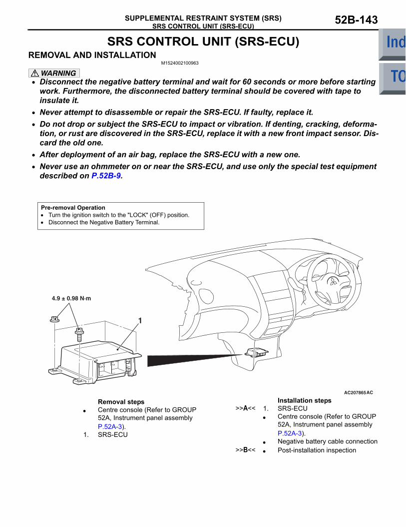
SRS CONTROL UNIT (SRS-ECU)SUPPLEMENTAL RESTRAINT SYSTEM (SRS) 52B-143
SRS CONTROL UNIT (SRS-ECU)REMOVAL AND INSTALLATION
M1524002100963
WARNING• Disconnect the negative battery terminal and wait for 60 seconds or more before starting
work. Furthermore, the disconnected battery terminal should be covered with tape to insulate it.
• Never attempt to disassemble or repair the SRS-ECU. If faulty, replace it.• Do not drop or subject the SRS-ECU to impact or vibration. If denting, cracking, deforma-
tion, or rust are discovered in the SRS-ECU, replace it with a new front impact sensor. Dis-card the old one.
• After deployment of an air bag, replace the SRS-ECU with a new one.• Never use an ohmmeter on or near the SRS-ECU, and use only the special test equipment
described on P.52B-9.
Pre-removal Operation• Turn the ignition switch to the "LOCK" (OFF) position.• Disconnect the Negative Battery Terminal.
AC207865
1
4.9 ± 0.98 N·m
AC
Removal steps • Centre console (Refer to GROUP
52A, Instrument panel assembly P.52A-3).
1. SRS-ECU
Installation steps >>A<< 1. SRS-ECU
• Centre console (Refer to GROUP 52A, Instrument panel assembly P.52A-3).
• Negative battery cable connection>>B<< • Post-installation inspection

SRS CONTROL UNIT (SRS-ECU)SUPPLEMENTAL RESTRAINT SYSTEM (SRS)52B-144
INSTALLATION SERVICE POINTS>>A<< SRS-ECU INSTALLATION
WARNINGThe SRS may not activate if SRS-ECU is not installed properly.
>>B<< POST-INSTALLATION INSPECTION1. Connect the negative battery cable.2. Turn the ignition key to "ON" position.
3. Does the "SRS" warning lamp illuminate for approximately seven seconds, and go out?
4. If no, refer to troubleshooting (Refer to P.52B-11).
INSPECTIONM1524002200465
WARNINGIf any problems are found, replace the SRS-ECU.
• Check the SRS-ECU and brackets for dents, cracks or deformation.
• Check the SRS-ECU connector for damage, and the terminals for deformation.
NOTE: For the checks other than the items above, refer to "Troubleshooting" (Refer to P.52B-11).
AC510172
<VR-X>
<Except-VR-X>
SRS warning lamp
SRS warning lamp AC
DRIVER'S AND PASSENGER'S (FRONT) AIR BAG MODULES AND CLOCK SPRINGSUPPLEMENTAL RESTRAINT SYSTEM (SRS) 52B-145
DRIVER'S AND PASSENGER'S (FRONT) AIR BAG MODULES AND CLOCK SPRING
REMOVAL AND INSTALLATIONM1524014500485
WARNING• Disconnect the negative battery terminal and wait for 60 seconds or more before starting
work. Furthermore, the disconnected battery terminal should be covered with tape to insulate it.
• Never attempt to disassemble or repair the air bag modules or clock spring. If faulty, replace it.
• Do not drop the air bag modules or clock spring or allow contact with water, grease or oil. Replace it if a dent, crack, deformation or rust is detected.
• The air bag modules should be stored on a flat surface is facing upward. Do not place anything on top of it.
• Do not expose the air bag modules to temperatures over 93°C.• After deployment of an air bag, replace the clock spring with a new one.• Wear gloves and safety glasses when handling air bags that have already deployed.• An undeployed air bag module should only be disposed of in accordance with the proce-
dures (Refer to P.52B-162).

DRIVER'S AND PASSENGER'S (FRONT) AIR BAG MODULES AND CLOCK SPRINGSUPPLEMENTAL RESTRAINT SYSTEM (SRS)52B-146
<DRIVERS AIR BAG MODULE AND CLOCK SPRING>Pre-removal Operation• Disconnect the Negative Battery Terminal.
AC208525
AC208935
AC207738
AC207739
AD
1
2
1
2
34
41 ± 8 N·m
2
Claw
3
9.0 ± 2.0 N·m
0.69 ± 0.15 N·mN
Claw
Drivers air bag module removal steps
<<A>> 1. Cover • Horn connector connection
<<B>> • Drivers air bag module connector connection
<<C>> 2. Drivers air bag module<<D>> 3. Steering wheel
Clock spring removal steps <<A>> 1. Cover
• Horn connector connection<<B>> • Drivers air bag module connector
connection<<C>> 2. Drivers air bag module<<D>> 3. Steering wheel
• Column cover (Refer to GROUP 37, Steering shaft P.37-92).
<<E>> 4. Clock springDrivers air bag module installation steps
>>A<< • Pre-installation inspection>>C<< 3. Steering wheel>>C<< 2. Drivers air bag module
• Drivers air bag module connector connection
• Horn connector connection>>D<< 1. Cover
• Negative (−) battery cable connection>>E<< • Post-installation inspection
Clock spring installation steps >>A<< • Pre-installation inspection>>B<< 4. Clock spring
• Column cover (Refer to GROUP 37, Steering shaft P.37-92).
>>C<< 3. Steering wheel>>C<< 2. Drivers air bag module
• Drivers air bag module connector connection
• Horn connector connection>>D<< 1. Cover
• Negative (−) battery cable connection>>E<< • Post-installation inspection
Drivers air bag module installation steps (Continued)
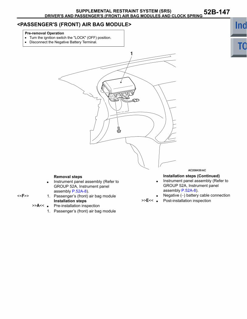
DRIVER'S AND PASSENGER'S (FRONT) AIR BAG MODULES AND CLOCK SPRINGSUPPLEMENTAL RESTRAINT SYSTEM (SRS) 52B-147
<PASSENGER'S (FRONT) AIR BAG MODULE>Pre-removal Operation• Turn the ignition switch the "LOCK" (OFF) position.• Disconnect the Negative Battery Terminal.
AC208439
1
AC
Removal steps • Instrument panel assembly (Refer to
GROUP 52A, Instrument panel assembly P.52A-8).
<<F>> 1. Passengers (front) air bag moduleInstallation steps
>>A<< • Pre-installation inspection1. Passengers (front) air bag module
• Instrument panel assembly (Refer to GROUP 52A, Instrument panel assembly P.52A-8).
• Negative (−) battery cable connection>>E<< • Post-installation inspection
Installation steps (Continued)

DRIVER'S AND PASSENGER'S (FRONT) AIR BAG MODULES AND CLOCK SPRINGSUPPLEMENTAL RESTRAINT SYSTEM (SRS)52B-148
REMOVAL SERVICE POINTS<<A>> COVER REMOVAL
1. Insert the special tool ornament remover (MB990784) as shown in the illustration to remove the cover.
2. Remove the horn connector secured to the cover.
<<B>> DRIVERS AIR BAG MODULE CONNECTOR DISCONNECTION
Disconnect the clock spring connector while com-pressing its locking button and sliding it to the direc-tion of an arrow.
<<C>> DRIVERS AIR BAG MODULE REMOVAL
WARNING• The air bag module must not be measured
with such equipment as an ohmmeter, nor disassembled.
• The removed air bag module should be stored in a clean, dry place with the deployment surface facing up.
1. Remove the drivers air bag module mounting screws (Torx screws) at the sides of the steering wheel.NOTE: Do not remove the screws from the hold-ers.
<<D>> STEERING WHEEL REMOVAL1. Position the steering wheel in the straight-ahead
position.
2. Use special tool steering wheel puller (MB990803) to remove the steering wheel.
<<E>> CLOCK SPRING REMOVALWARNING
The removed clock spring should be stored in a clean, dry place.
AC211761AB
MB990784
AC209070AE
Horn connector fixing point
Cover
AC302435
Locking button
AI
Clock spring connector
Steering wheel connector
AC312338
Section A-A
Mounting screw (Torx screw)
A
A
AB
AC000991
MB990803
AD

DRIVER'S AND PASSENGER'S (FRONT) AIR BAG MODULES AND CLOCK SPRINGSUPPLEMENTAL RESTRAINT SYSTEM (SRS) 52B-149
<<F>> PASSENGERS (FRONT) AIR BAG MODULE REMOVAL
WARNING• When the passengers (front) air bag mod-
ule is removed, do not damage the engagement of the pawls.
• The removed passengers (front) air bag module should be stored in a clean, dry place with facing the deployment surface facing up.
INSTALLATION SERVICE POINTS>>A<< PRE-INSTALLATION INSPECTION
WARNINGDispose of air bag modules only according to the specified procedure (Refer to P.52B-162).1. When installing the new air bag modules and
clock spring, refer to INSPECTION (P.52B-151).2. Connect the negative (−) battery cable.
CAUTION
To prevent damage to M.U.T.-III, always turn the ignition, switch to the LOCK (OFF) position before connecting or disconnecting M.U.T.-III.3. Connect M.U.T.-III to the diagnosis connector.
4. Turn the ignition switch to the ON position.5. Check diagnosis codes using M.U.T.-III to ensure
that the SRS operates properly.At this time, check that no diagnosis code except 21 and 24 are set.DANGER
Wait at least 60 seconds after disconnecting the battery cable before doing any further work (Refer to P.52B-5).6. Turn the ignition switch to the "LOCK" (OFF)
position. Disconnect the negative (−) battery cable and tape the terminal to prevent accidental connection and air bags deployment.
>>B<< CLOCK SPRING INSTALLATIONWARNING
Ensure that the clock springs mating marks are properly aligned. If not, the steering wheel may not rotate completely during a turn, or the flat cable in the clock spring could be damaged, This would prevent nor-mal SRS operation and possibly cause seri-ous injury to the driver.
1. Align the mating marks of the clock spring. <Mating Mark Alignment>Turn the clock spring clockwise fully. Then turn it back approximately 3 3/4 turns anticlockwise to align the mating marks.
2. Turn the front wheels to the straight-ahead position. Then install the clock spring to the column switch.
AC206895AC
Diagnosisconnector
MB991827
MB991824
MB991910AC300168
Mating marks
AB

DRIVER'S AND PASSENGER'S (FRONT) AIR BAG MODULES AND CLOCK SPRINGSUPPLEMENTAL RESTRAINT SYSTEM (SRS)52B-150
>>C<< STEERING WHEEL/DRIVERS AIR BAG MODULE INSTALLATION
CAUTIONWhen installing the steering wheel, and drivers air bag module ensure that the harness of the clock spring does not become caught or tangled.1. Before installing the steering wheel, and drivers
air bag module turn the vehicles front wheels to the straight-ahead position and align the mating marks of the clock spring.
2. After securing the steering wheel, turn the steering wheel all the way in both directions to confirm that the steering wheel rotation is normal.
>>D << COVER INSTALLATION
1. Secure the horn connector to the cover.2. Install the cover to the steering wheel assembly.
>>E<< POST-INSTALLATION INSPECTION1. Reconnect the negative (−) battery cable.2. Turn the ignition switch to ON position.
3. Does the "SRS" warning lamp illuminate for approximately seven seconds, and go out?
4. If yes, the SRS system is functioning properly. If no, refer to P.52B-10.
AC209070AE
Horn connector fixing point
Cover
AC510172
<VR-X>
<Except-VR-X>
SRS warning lamp
SRS warning lamp AC
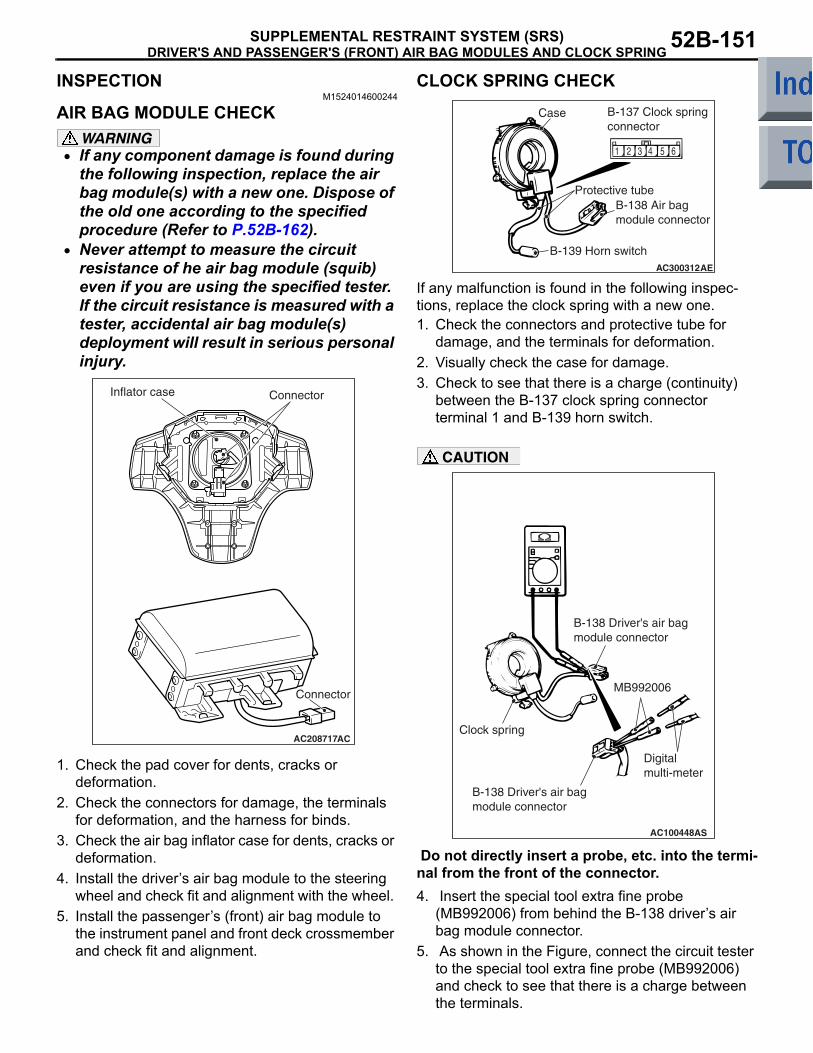
DRIVER'S AND PASSENGER'S (FRONT) AIR BAG MODULES AND CLOCK SPRINGSUPPLEMENTAL RESTRAINT SYSTEM (SRS) 52B-151
INSPECTIONM1524014600244
AIR BAG MODULE CHECKWARNING
• If any component damage is found during the following inspection, replace the air bag module(s) with a new one. Dispose of the old one according to the specified procedure (Refer to P.52B-162).
• Never attempt to measure the circuit resistance of he air bag module (squib) even if you are using the specified tester. If the circuit resistance is measured with a tester, accidental air bag module(s) deployment will result in serious personal injury.
1. Check the pad cover for dents, cracks or deformation.
2. Check the connectors for damage, the terminals for deformation, and the harness for binds.
3. Check the air bag inflator case for dents, cracks or deformation.
4. Install the drivers air bag module to the steering wheel and check fit and alignment with the wheel.
5. Install the passengers (front) air bag module to the instrument panel and front deck crossmember and check fit and alignment.
CLOCK SPRING CHECK
If any malfunction is found in the following inspec-tions, replace the clock spring with a new one.1. Check the connectors and protective tube for
damage, and the terminals for deformation.2. Visually check the case for damage.3. Check to see that there is a charge (continuity)
between the B-137 clock spring connector terminal 1 and B-139 horn switch.
CAUTION
Do not directly insert a probe, etc. into the termi-nal from the front of the connector.4. Insert the special tool extra fine probe
(MB992006) from behind the B-138 drivers air bag module connector.
5. As shown in the Figure, connect the circuit tester to the special tool extra fine probe (MB992006) and check to see that there is a charge between the terminals.
AC208717
ConnectorInflator case
Connector
AC
5 61 2 3 4
AC300312AE
Case B-137 Clock springconnector
Protective tubeB-138 Air bagmodule connector
B-139 Horn switch
AC100448
Clock spring
MB992006
Digitalmulti-meter
AS
B-138 Driver's air bagmodule connector
B-138 Driver's air bagmodule connector

SIDE AND CURTAIN AIR BAG MODULESSUPPLEMENTAL RESTRAINT SYSTEM (SRS)52B-152
SIDE AND CURTAIN AIR BAG MODULESREMOVAL AND INSTALLATION
M1524014800248
WARNING• Disconnect the negative battery terminal and wait for 60 seconds or more before starting
work. Also, the disconnected battery terminal should be insulated with tape (Refer to P.52B-5).
• Never attempt to disassemble or repair the air bag modules. If faulty, just replace with new one(s).
• Do not drop the air bag modules or allow contact with water, grease or oil. Replace if a dent, crack, deformation or rust are present.
• Store the air bag modules on a flat surface with the deployment surface facing up. Do not place anything on top of them.
• Do not store the air bag modules in a place more than 93°C.• When the side and curtain air bags have been deployed, replace the front seatback
assembly and curtain air bag modules with new ones.• Put on gloves and safety glasses when handling deployed air bags.• When discarding the undeployed air bag module(s), be sure to deploy the air bag(s) in
advance as specified in the service procedure (Refer to P.52B-162).
<SIDE-AIRBAG MODULE>Pre-removal Operation• Turn the ignition switch to the "LOCK" (OFF) position.• Disconnect the Negative Battery Terminal.
AC208417
1
AD
Side air bag module removal steps <<A>> 1. Front seat assembly
Side air bag module installation steps
>>A<< • Pre-installation inspection1. Front seat assembly
• Negative (−) battery cable connection>>D<< • Post-installation inspection
Side air bag module installation steps (Continued)

SIDE AND CURTAIN AIR BAG MODULESSUPPLEMENTAL RESTRAINT SYSTEM (SRS) 52B-153
<CURTAIN AIR BAG MODULE>
REMOVAL SERVICE POINTS<<A>> FRONT SEAT ASSEMBLY REMOVAL
WARNINGDispose of air bag modules only according to the specified procedure (Refer to P.52B-162).Refer to GROUP52A, Front seat assembly P.52A-23.
<<B>> CONNECTOR REMOVAL
Use a flat-tipped screwdriver to pull out forward and unlock the locking button of the curtain air bag har-ness-side connector.
Pre-removal Operation• Turn the ignition switch to the "LOCK" (OFF) position.• Disconnect the Negative Battery Terminal.
AC208406NOTE
: Harness clip positions
AC
13
2 4
Curtain air bag module removal steps
• Headlining (Refer to GROUP 52A, Headlining P.52A-16.)
<<B>> 1. Connector2. Curtain air bag module3. Strap guide bracket4. Curtain air bag harness
Curtain air bag module installation steps
>>A<< • Pre-installation inspection>>B<< 4. Curtain air bag harness
3. Strap guide bracket>>C<< 2. Curtain air bag module
1. Connector• Headlining (Refer to GROUP 52A,
Headlining P.52A-16.)• Negative (−) battery cable connection
>>D<< • Post-installation inspection
AC208384AC
Locking button
Inflator connector
Curtain air bagharness connector
Flat-tip screwdriver

SIDE AND CURTAIN AIR BAG MODULESSUPPLEMENTAL RESTRAINT SYSTEM (SRS)52B-154
INSTALLATION SERVICE POINTS>>A<< PRE-INSTALLATION INSPECTION
WARNINGDispose of air bag modules only according to the specified procedure (Refer to P.52B-162).1. When installing the new air bag modules, refer to
INSPECTION (P.52B-155).2. Connect the negative (−) battery cable.
CAUTION
To prevent damage to M.U.T.-III, always turn the ignition, switch to the LOCK (OFF) position before connecting or disconnecting M.U.T.-III.3. Connect M.U.T.-III to the diagnosis connector.4. Turn the ignition switch to the ON position.5. Check diagnosis codes using M.U.T.-III to ensure
that the SRS operates properly.Confirm that the diagnosis codes other than 71, 81, 3A and 4A are not set.DANGER
Wait at least 60 seconds after disconnecting the battery cable before doing any further work. (Refer to P.52B-5.)6. Turn the ignition switch to the "LOCK" (OFF)
position. 7. Disconnect the negative (−) battery cable and
tape the terminal to prevent accidental connection and air bags deployment.
>>B<< CURTAIN AIR BAG HARNESS INSTALLATION
CAUTION• Secure the harness clip certainly and return it
to the back side of air bag.• Connect the connector with the inflator cer-
tainly.
>>C<< CURTAIN AIR BAG MODULE INSTALLATION
CAUTION•
Take care not to contort the curtain air bag when installing it.
• Take care that the surrounding components do not trap the air bag.
• Take care that the front pillar trim clips or other do not trap the strap.
Hang the strap on the strap guide.
>>D<< POST-INSTALLATION INSPECTION1. Reconnect the negative (−) battery cable.2. Turn the ignition switch to ON position.
AC206895AC
Diagnosisconnector
MB991827
MB991824
MB991910
AC208759AC
Strap guide
Strap
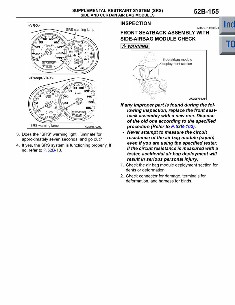
SIDE AND CURTAIN AIR BAG MODULESSUPPLEMENTAL RESTRAINT SYSTEM (SRS) 52B-155
3. Does the "SRS" warning light illuminate for approximately seven seconds, and go out?
4. If yes, the SRS system is functioning properly. If no, refer to P.52B-10.
INSPECTIONM1524014900074
FRONT SEATBACK ASSEMBLY WITH SIDE-AIRBAG MODULE CHECK
WARNING•
If any improper part is found during the fol-lowing inspection, replace the front seat-back assembly with a new one. Dispose of the old one according to the specified procedure (Refer to P.52B-162).
• Never attempt to measure the circuit resistance of the air bag module (squib) even if you are using the specified tester. If the circuit resistance is measured with a tester, accidental air bag deployment will result in serious personal injury.
1. Check the air bag module deployment section for dents or deformation.
2. Check connector for damage, terminals for deformation, and harness for binds.
AC510172
<VR-X>
<Except-VR-X>
SRS warning lamp
SRS warning lamp AC
AC208794AF
Side-airbag moduledeployment section

SIDE AND CURTAIN AIR BAG MODULESSUPPLEMENTAL RESTRAINT SYSTEM (SRS)52B-156
CURTAIN AIR BAG MODULE CHECKWARNING
•
If any improper part is found during the fol-lowing inspection, replace the curtain air bag module (squib) assembly with a new one. Dispose of the old one according to the specified procedure (Refer to P.52B-162).
• Never attempt to measure the circuit resistance of the air bag module (squib) even if you are using the specified tester. If the circuit resistance is measured with a tester, accidental air bag deployment will result in serious personal injury.
1. Check that the curtain air bag deployment part of the headlining is normal.
2. Check the inflator surface for cracks, dents or deformations.
3. Check the air bag for breakage.4. Check the connector for damage, the terminal for
deformation and the harness for binding.
AC208936
Curtain air bag moduledeployment section
AC

SIDE IMPACT SENSORSUPPLEMENTAL RESTRAINT SYSTEM (SRS) 52B-157
SIDE IMPACT SENSORREMOVAL AND INSTALLATION
M1524004600771
WARNING• Disconnect the negative battery terminal and wait for 60 seconds or more before starting
work. Furthermore, the disconnected battery terminal should be covered with tape to insulate it.
• Never attempt to disassemble or repair the side impact sensors. If faulty, replace it.• Do not drop or subject the side impact sensors to impact or vibration. If denting, cracking,
deformation, or rust are discovered in the side impact sensors, replace it with a new front impact sensor. Discard the old one.
• After deployment of an air bag, replace the side impact sensors with a new one.• Never use an ohmmeter on or near the side impact sensors, and use only the special test
equipment described on P.52B-9.
NOTE: The figure shows the side impact sensor (LH).
Pre-removal Operation• Turn the ignition key to the "LOCK" (OFF) position.• Disconnect the Negative Battery Terminal.
AC20792010 ± 2 N·m
AD
1
Forward
Side impact sensor removal steps
• Centre pillar trim lower (Refer to GROUP 52A, Trims P.52A-11.)
1. Side impact sensorSide impact sensor installation steps
>>A<< • Pre-installation inspection>>B<< 1. Side impact sensor
• Centre pillar trim lower (Refer to GROUP 52A, Trims P.52A-11.)
• Negative battery cable connector>>C<< • Post-installation inspection
Side impact sensor installation steps (Continued)

SIDE IMPACT SENSORSUPPLEMENTAL RESTRAINT SYSTEM (SRS)52B-158
INSTALLATION SERVICE POINTS>>A<< PRE-INSTALLATION INSPECTIONEven new side impact sensor requires inspection before installation (Refer to the previous item "INSPECTION" P.52B-158).
>>B<< SIDE IMPACT SENSOR INSTALLATION
WARNINGThe side impact sensor, unless properly installed, does not operate properly, thereby resulting in serious injury or death of the vehicle's occupants.
>>C<< POST-INSTALLATION INSPECTION1. Connect the negative battery cable.2. Turn the ignition key to "ON" position.
3. Does the SRS warning lamp illuminate for about 7 seconds, and then remain extinguished for at least 5 seconds after turning OFF?
4. If no, refer to troubleshooting (Refer to P.52B-11).
INSPECTIONM1524004700433
WARNINGIf any problems, replace the sensor.
1.
Check the side impact sensor and bracket for dents, cracks or deformation.
2. Check the connector for damage, and terminal for deformation.
3. Check the centre pillar and the quarter inner panel for deformation or corrosion.
NOTE: For the checks other than the items above, refer to Troubleshooting (Refer to P.52B-11) .
AC510172
<VR-X>
<Except-VR-X>
SRS warning lamp
SRS warning lamp AC
AC311530
Side impact sensor (front)
AC
Front seat beltretractor

SEAT BELTS WITH PRE-TENSIONERSUPPLEMENTAL RESTRAINT SYSTEM (SRS) 52B-159
SEAT BELTS WITH PRE-TENSIONERREMOVAL AND INSTALLATION
M1524004100851
WARNING• Never attempt to disassemble or repair the seat belt pre-tensioner. If faulty, replace it.• Be extremely careful when handling the seat with pre-tensioner. Do not subject it to
shocks, drop it, bring it close to strong magnets or allow contact with water, grease or oil. Always replace it with a new part if any dents, cracks or deformation is found.
• Do not place anything on top of the seat belt pre-tensioner.• Do not expose the seat belt pre-tensioner to temperatures over 90°C.• After operating the seat belt pre-tensioner, replace the seat belt pre-tensioner with a new
part.• Gloves and protective goggles should be worn when handling a seat belt pre-tensioner
once it has been used.• If disposing of a seat belt with pre-tensioner which has not yet been operated, its seat belt
pre-tensioner should be operated first before disposal (Refer to P.52B-162).
NOTE: The figure shows the seat belt with pre-ten-sioner (RH).
Pre-removal Operation• Turn the ignition key to the "LOCK" (OFF) position.• Disconnect the Negative Battery Terminal.
AC208786
4
2 1
5
3
44 ± 10 N·m
44 ± 10 N·m
AC
Removal steps 1. Sash guide cover2. Seat belt shoulder anchor bolt3. Seat belt lower anchor bolt• Centre pillar trim, lower (Refer to
GROUP 52A, Trims P.52A-11).<<A>> 4. Pre-tensioner connector connection
5. Seat belt with pre-tensionerInstallation steps
>>A<< • Pre-installation inspection5. Seat belt with pre-tensioner
>>B<< 4. Pre-tensioner connector connection• Centre pillar trim, lower (Refer to
GROUP 52A, Trims P.52A-11).3. Seat belt lower anchor bolt2. Seat belt shoulder anchor bolt1. Sash guide cover• Negative battery cable connection
>>C<< • Post-installation inspection
Installation steps (Continued)
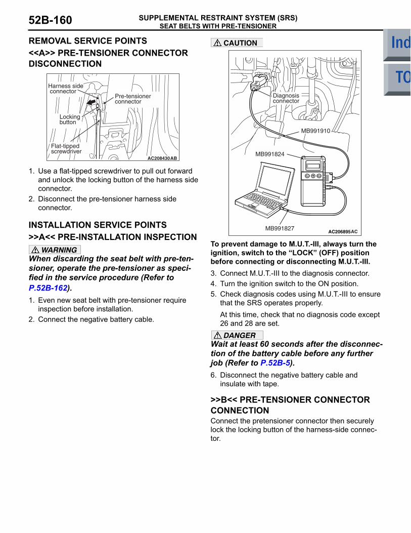
SEAT BELTS WITH PRE-TENSIONERSUPPLEMENTAL RESTRAINT SYSTEM (SRS)52B-160
REMOVAL SERVICE POINTS<<A>> PRE-TENSIONER CONNECTOR DISCONNECTION
1. Use a flat-tipped screwdriver to pull out forward and unlock the locking button of the harness side connector.
2. Disconnect the pre-tensioner harness side connector.
INSTALLATION SERVICE POINTS>>A<< PRE-INSTALLATION INSPECTION
WARNINGWhen discarding the seat belt with pre-ten-sioner, operate the pre-tensioner as speci-fied in the service procedure (Refer to P.52B-162).1. Even new seat belt with pre-tensioner require
inspection before installation.2. Connect the negative battery cable.
CAUTION
To prevent damage to M.U.T.-III, always turn the ignition, switch to the LOCK (OFF) position before connecting or disconnecting M.U.T.-III.3. Connect M.U.T.-III to the diagnosis connector.4. Turn the ignition switch to the ON position.5. Check diagnosis codes using M.U.T.-III to ensure
that the SRS operates properly.At this time, check that no diagnosis code except 26 and 28 are set.DANGER
Wait at least 60 seconds after the disconnec-tion of the battery cable before any further job (Refer to P.52B-5).6. Disconnect the negative battery cable and
insulate with tape.
>>B<< PRE-TENSIONER CONNECTOR CONNECTIONConnect the pretensioner connector then securely lock the locking button of the harness-side connec-tor.
AC208430AB
Pre-tensionerconnector
Locking button
Harness side connector
Flat-tipped screwdriver
AC206895AC
Diagnosisconnector
MB991827
MB991824
MB991910

SEAT BELTS WITH PRE-TENSIONERSUPPLEMENTAL RESTRAINT SYSTEM (SRS) 52B-161
>> C<< POST-INSTALLATION INSPECTION1. Connect the negative battery cable.2. Turn the ignition key to "ON" position.
3. Does the "SRS" warning lamp illuminate for approximately seven seconds, and go out?
4. If no, refer to troubleshooting (Refer to P.52B-11).
INSPECTIONM1524004200342
WARNING• If any component damage is found during
the following inspection, replace the seat belt with pre-tensioner with a new one. Dispose of the old one according to the specified procedure (Refer to P.52B-162).
• Never attempt to measure the circuit resistance of the seat belt pre-tensioner even if you are using the specified tester. If the circuit resistance is measured with a tester, accidental seat belt pre-tensioner operation will result in serious personal injury.
1. Check the pre-tensioner deployment section for dents and deformation.
2. Check the harness and connector for damage and the terminals for deformation.
AC510172
<VR-X>
<Except-VR-X>
SRS warning lamp
SRS warning lamp AC

AIR BAG MODULE AND SEAT BELT PRE-TENSIONER DISPOSAL PROCEDURESSUPPLEMENTAL RESTRAINT SYSTEM (SRS)52B-162
AIR BAG MODULE AND SEAT BELT PRE-TENSIONER DISPOSAL PROCEDURES
M1524001201108Before disposing of an air bag or a vehicle equipped with an air bag, follow the procedures below to deploy the air bag.UNDEPLOYED AIR BAG MODULE DIS-POSAL
WARNING• If the vehicle is to be scrapped or other-
wise disposed of, deploy the air bags and operate the seat belt pre-tensioner inside the vehicle. If the vehicle will continue to be used and only the air bag modules and seat belt pre-tensioner are to be disposed of, deploy the air bags and operate the seat belt pre-tensioner outside the vehi-cle.
• Since a large amount of smoke is pro-duced when the air bag is deployed and the seat belt pre-tensioner is operated, avoid residential areas whenever possi-ble.
• Since there is loud noise when the air bags are deployed and when the seat belt pre-tensioner are operated, avoid residen-tial areas whenever possible. If anyone is nearby, give warning of the impending noise.
• Suitable ear protection should be worn by personnel performing these procedures or by people in the immediate area.
DEPLOYMENT INSIDE THE VEHICLE (WHEN DISPOSING OF A VEHICLE) <DRIVER'S AIR BAG MODULE>1. Move the vehicle to an isolated spot.
DANGERWait at least 60 seconds after the disconnec-tion of the battery cable before any further job (Refer to P.52B-5).2. Disconnect the negative and positive battery
cables from the battery terminals, and then remove the battery from the vehicle.
3. Remove the column cover lower (Refer to GROUP 37, Steering shaft P.37-92).
4. Remove the connection between the B-136 clock spring connector (4-pin) and the harness side connector (4-pin).NOTE: Once disconnected from the instrument panel wiring harness, both electrodes of the clock spring connector short automatically. This pre-vents the driver's air bag from accidental deploy-ment caused by static, etc.
5. Obtain two suitable wires, which are 6 meters or longer, as deployment wires. Then connect the wires at one end to short.
6. Touch the vehicle's body with bare hands to discharge static in you.
AC300379
B-136 Clock springconnector (4-pin)
B-136 Harness sideconnector (4-pin)
AE
AC300381AE
Deployment wires
Connection
6 m or longer

AIR BAG MODULE AND SEAT BELT PRE-TENSIONER DISPOSAL PROCEDURESSUPPLEMENTAL RESTRAINT SYSTEM (SRS) 52B-163
7. Cut with a pliers, etc. the instrument panel wiring harness shown in the figure of the instructions, while the B-136 clock spring connector is disconnected.NOTE: The disconnection location should be suf-ficiently away from the B-136 harness side con-nector with consideration to the expansion harness connection location upon disconnections.
8. Connect the deployment wires on the two instrument panel wiring harnesses disconnected, cover the connection areas with insulator tape and then pull out the deployment wires outside the vehicle.
9. Connect the B-136 harness side connector connected with an expansion harness to the B-136 clock spring connector.WARNING
If the glass is scratched, air bag deployment could cause it to crack and fly out of the vehicle, so always put a cover over the vehi-cle.10.To suppress the operation sound as much as
possible completely close all door windows, close the doors and put the cover on the vehicle.
WARNING• Before deploying the air bag in this man-
ner, first check to be sure that there is no one in or near the vehicle. Wear safety glasses.
• The inflator will be quite hot immediately following the deployment, so wait at least 30 minutes to allow it to cool before attempting to handle it. Although not poi-sonous, do not inhale gas from the air bag deployment. See Deployed Air Bag Mod-ule and Operated Seat Belt Pre-tensioner Disposal (Refer to P.52B-176) for post-deployment handling instructions.
• If the air bag module fails to deploy, do not go near the module. Contact your dis-tributor.
11.At a location as far away from the vehicle as possible, disconnect the two connected wires from each other, and connect them to the two terminals of the battery (which has been removed from the vehicle) to deploy the air bag.
12.After deployment, dispose of the air bag module according to the Deployed Air Bag Module and Operated Seat Belt Pre-tensioner Disposal (Refer to P.52B-176).
DEPLOYMENT INSIDE THE VEHICLE (WHEN DISPOSING OF A VEHICLE) <PASSENGER'S (FRONT) AIR BAG MODULE>1. Move the vehicle to an isolated spot.
DANGERWait at least 60 seconds after the disconnec-tion of the battery cable before any further job (Refer to P.52B-5).2. Disconnect the negative and positive battery
cables from the battery terminals, and then remove the battery from the vehicle.
3. Remove the glove box (Refer to GROUP 52A, Instrument Panel P.52A-3).
AC300384
Deployment wire
AE
Insulator tape
B-136 Clock springconnector (4-pin)
Connection
B-136 Harness sideconnector (4-pin)
AC300388AD
Cover
Deployment wire6 m or longer

AIR BAG MODULE AND SEAT BELT PRE-TENSIONER DISPOSAL PROCEDURESSUPPLEMENTAL RESTRAINT SYSTEM (SRS)52B-164
4. Remove the connection between the B-06 passenger's (front) air bag module connector (2-pin, red) and the harness side connector (2-pin, red).NOTE: Once disconnected from the instrument panel wiring harness, both electrodes of the pas-senger's (front) air bag module short automati-cally. This prevents the passenger's (front) air bag from accidental deployment caused by static, etc.
5. Connect deployment wires longer than 6 m to each SRS air bag adapter harness (MB686560) and insulate the connections with insulator tape. Also, connect the deployment wires in the other ends to short, thereby preventing the passenger's (front) air bag from accidental deployment caused by static etc.
6. Connect the B-06 passenger's (front) air bag module connector (2-pin, red) to special tool SRS air bag adapter harness (MB686560) and move the deployment wires out of the vehicle.
WARNING
If the glass is scratched, air bag deployment could cause it to crack and fly out of the vehicle, so always put a cover over the vehi-cle.7. To suppress the operation sound as much as
possible completely close all door windows, close the doors and put the cover on the vehicle.WARNING
• Before deploying the air bag in this man-ner, first check to be sure that there is no one in or near the vehicle. Wear safety glasses.
• The inflator will be quite hot immediately following the deployment, so wait at least 30 minutes to allow it to cool before attempting to handle it. Although not poi-sonous, do not inhale gas from the air bag deployment. See Deployed Air Bag Mod-ule and Operated Seat Belt Pre-tensioner Disposal (Refer to P.52B-176) for post-deployment handling instructions.
• If the air bag module fails to deploy, do not go near the module. Contact your dis-tributor.
8. At a location as far away from the vehicle as possible, disconnect the two connected wires from each other, and connect them to the two terminals of the battery (which has been removed from the vehicle) to deploy the air bag.
9. After deployment, dispose of the air bag module according to the Deployed Air Bag Module and Operated Seat Belt Pre-tensioner Disposal (Refer to P.52B-176).
AC206286
Connector: B-06
2 1
Harness side connector (front view)
B-06 (R)
AG
Glove box striker
AC300419AC
Connection
Deployment wires
MB686560
Insulator tape
6 m or longer
AC300420AM
MB686560
B-06 Passenger's (front) air bag moduleconnector (2-pin, red)Deployment wires
AC300388AD
Cover
Deployment wire6 m or longer

AIR BAG MODULE AND SEAT BELT PRE-TENSIONER DISPOSAL PROCEDURESSUPPLEMENTAL RESTRAINT SYSTEM (SRS) 52B-165
DEPLOYMENT INSIDE THE VEHICLE (WHEN DISPOSING OF A VEHICLE) <SIDE-AIRBAG MODULE>1. Move the vehicle to an isolated spot.
WARNINGWait at least 60 seconds after disconnecting the battery cables before doing any further work (Refer to P.52B-5).2. Disconnect the negative and positive battery
cables from the battery terminals, and then remove the battery from the vehicle.WARNING
The side-airbag modules for both the driver's side and passenger's side should be deployed.3. Remove the connection between the C-23 or
C-25 side-airbag module connector (2-pin, red) and the harness side connector (2-pin, red).NOTE: Once disconnected from the instrument panel wiring harness, both electrode of the side-airbag module connector short automatically. This prevents the side-airbag from accidental deployment caused by static etc.
4. Connect deployment wires longer than 6 m to each SRS air bag adapter harness (MB686560) and insulate the connections with insulator tape. Also, connect the deployment wires in the other ends to short, thereby preventing the side-airbag from accidental deployment caused by static etc.
5. Connect the C-23 or C-25 side-airbag module connector (2-pin, red) to SRS air bag adapter harness (MB686560) and move the deployment wire out of the vehicle.WARNING
If the glass is scratched, air bag deployment could cause it to crack and fly out of the vehicle, so always put a cover over the vehi-cle.6. To suppress the operation sound as much as
possible completely close all door windows, close the doors and put the vehicle.
AC208794AG
C-23 or C-25 Harnessside connector(2-pin, red)
C-23 or C-25Side air bagconnector (2-pin, red)
AC300419AC
Connection
Deployment wires
MB686560
Insulator tape
6 m or longer
AC300444AF
MB686560
C-23 or C-25Side-airbag moduleconnector (2-pin, red)Deployment wires
AC300388AD
Cover
Deployment wire6 m or longer

AIR BAG MODULE AND SEAT BELT PRE-TENSIONER DISPOSAL PROCEDURESSUPPLEMENTAL RESTRAINT SYSTEM (SRS)52B-166
WARNING• Before deploying the air bag in this man-
ner, first check to be sure that there is no one in or near the vehicle. Wear safety glasses.
• The inflator will be quite hot immediately following the deployment, so wait at least 30 minutes to allow it to cool before attempting to handle it. Although not poi-sonous, do not inhale gas from the air bag deployment. See Deployed Air Bag Mod-ule and Operated Seat Belt Pre-tensioner Disposal (Refer to P.52B-176) for post-deployment handling instructions.
• If the air bag module fails to deploy, do not go near the module. Contact your dis-tributor.
7. At a location as far away from the vehicle as possible, disconnect the two connected wires from each other, and connect them to the two terminals of the battery (which has been removed from the vehicle) to deploy the air bag.
8. After deployment, dispose of the front seatback assembly (air bag module) according to the Deployed Air Bag Module and Operated Seat Belt Pre-tensioner Disposal (Refer to P.52B-176).
DEPLOYMENT INSIDE THE VEHICLE (WHEN DISPOSING OF A VEHICLE) <CURTAIN AIR BAG MODULE>1. Move the vehicle to an isolated spot.
WARNINGWait at least 60 seconds after disconnecting the battery cables before doing any further work (Refer to P.52B-5).2. Disconnect the negative and positive battery
cables from the battery terminals, and then remove the battery from the vehicle.WARNING
The curtain air bag modules for both the right side and left side should be deployed.3. Remove the headlining (Refer to GROUP 52A,
Headlining P.52A-16).
4. Execute the following steps to disconnect the connection between C-07 or C-10 curtain air bag module connector (2-pin) and harness side connector (2-pin, black).NOTE: Once disconnected from the curtain air bag wiring harness, both electrode of the curtain air bag module connector short automatically. This prevents the curtain air bag module from accidental deployment caused by static etc.(1) Use a flat-tipped screwdriver to pull out
forward and unlock the locking button of the harness-side connector (2-pin, black).
(2) Disconnect the C-07 or C-10 harness side connector.
5. Connect deployment wires longer than 6 m to each special tool SRS air bag adapter harness (MB991885) and insulate the connections with insulator tape. Also, connect the deployment wires in the other ends to short, thereby preventing the curtain air bag from accidental deployment caused by static etc.
AC208384AU
C-07 or C-10 Curtain air bagmodule connector (2-pin)
Flat-tip screwdriver
Locking button
C-07 or C-10Harness sideconnector(2-pin, black)
AC300447AC
Connection
Deployment wires
MB991885
Insulator tape
6 m or longer

AIR BAG MODULE AND SEAT BELT PRE-TENSIONER DISPOSAL PROCEDURESSUPPLEMENTAL RESTRAINT SYSTEM (SRS) 52B-167
6. Connect the C-07 or C-10 curtain air bag module 2-pin connector (black) to special tool SRS air bag adapter harness (MB991885) and move the deployment harness out of the vehicle.
WARNING
If the glass is scratched, air bag deployment could cause it to crack and fly out of the vehicle, so always put a cover over the vehi-cle.7. To suppress the operation sound as much as
possible completely close all door windows, close the doors and put the vehicle.
WARNING• Before deploying the air bag in this man-
ner, first check to be sure that there is no one in or near the vehicle. Wear safety glasses.
• The inflator will be quite hot immediately following the deployment, so wait at least 30 minutes to allow it to cool before attempting to handle it. Although not poi-sonous, do not inhale gas from the air bag deployment. See Deployed Air Bag Mod-ule and Operated Seat Belt Pre-tensioner Disposal (Refer to P.52B-176) for post-deployment handling instructions.
• If the air bag module fails to deploy, do not go near the module. Contact your dis-tributor.
8. At a location as far away from the vehicle as possible, disconnect the two connected wires from each other, and connect them to the two terminals of the battery (which has been removed from the vehicle) to deploy the air bag.
9. After deployment, dispose of the curtain air bag module according to the Deployed Air Bag Module and Operated Seat Belt Pre-tensioner Disposal (Refer to P.52B-176).
DEPLOYMENT INSIDE THE VEHICLE (WHEN DISPOSING OF A VEHICLE) <SEAT BELT PRE-TENSIONER>1. Move the vehicle to an isolated spot.
DANGERWait at least 60 seconds after disconnecting the battery cables before doing any further work (Refer to P.52B-5).2. Disconnect the negative and positive battery
cables from the battery terminals, and then remove the battery from the vehicle.
3. Remove the centre pillar lower trim (Refer to GROUP 52A, Trim P.52A-11).
AC301520AF
MB991885
Deploymentwires
C-07 or C-10Curtain air bagmodule 2-pin connector
AC300388AD
Cover
Deployment wire6 m or longer

AIR BAG MODULE AND SEAT BELT PRE-TENSIONER DISPOSAL PROCEDURESSUPPLEMENTAL RESTRAINT SYSTEM (SRS)52B-168
4. Execute the following steps to disconnect the connection between C-20 or C-28 seat belt pre-tensioner connector (2-pin) and harness side connector (2-pin, black).NOTE: Once disconnected from the instrument panel wiring harness, both electrode of the seat belt pre-tensioner connector short automatically. This prevents the seat belt pre-tensioner from accidental deployment caused by static etc.(1) Use a flat-tipped screwdriver to pull out
forward and unlock the locking button of the harness-side connector (2-pin, black).
(2) Disconnect the C-20 or C-28 harness side connector.
5. Connect deployment wires longer than 6 m to each special tool SRS air bag adapter harness (MB991885) and insulate the connections with insulator tape. Also, connect the deployment wires in the other ends to short, thereby preventing the seat belt pre-tensioner from accidental deployment caused by static etc.
6. Connect the C-20 or C-28 seat belt pre-tensioner connector (2-pin) to special tool SRS air bag adapter harness (MB991885) and move the deployment wires out of the vehicle.
7. Close all the door windows fully to avoid operating sound as much as possible.WARNING
• Before operating the seat belt pre-ten-sioner in this manner, first check to be sure that there is no one in or near the vehicle. Wear safety glasses.
• The inflator will be quite hot immediately following the operation, so wait at least 30 minutes to allow it to cool before attempt-ing to handle it. Although no poisonous, do not inhale gas from the seat belt pre-tensioner operation. See Deployed Air Bag and Operated Seat Belt pre-tensioner Disposal (Refer to P.52B-176) for post-operation handling instructions.
• If the seat belt pre-tensioner fails to oper-ate, do not go near the seat belt pre-ten-sioner. Contact your distributor.
8. At a location as far away from the vehicle as possible, disconnect the two connected wires from each the, and connect them to the two terminals of the battery (which has been removed from the vehicle) to operating the seat belt pre-tensioner.
9. After operation, dispose of the seat belt pre-tensioner according to the Deployed Air Bag Module operated seat belt pre-tensioner Disposal (Refer to P.52B-176).
AC208430AG
Locking button
Flat-tipped screwdriver
C-20 or C-28Harness sideconnector(2-pin, black)
C-20 or C-28Seat beltpre-tensionerconnector (2-pin)
AC300447AC
Connection
Deployment wires
MB991885
Insulator tape
6 m or longer
AC208427
C-20 or C-28Seat beltpre-tensioner2-pin connector
AD
MB991885
Deploymentwires

AIR BAG MODULE AND SEAT BELT PRE-TENSIONER DISPOSAL PROCEDURESSUPPLEMENTAL RESTRAINT SYSTEM (SRS) 52B-169
DEPLOYMENT OUTSIDE THE VEHICLE <AIR BAG MODULE (DRIVER'S SIDE)>
WARNING• This should be carried out in a wide, flat
area at least 6 m away from obstacles and other people.
• Do not deploy outside if wind is high. Even in a soft wind, ignite to windward of the air bag modules. DANGER
Wait at least 60 seconds after disconnecting the battery cables before doing any further work (Refer to P.52B-5).1. Disconnect the negative and positive battery
cables from the battery terminals, and then remove the battery from the vehicle.WARNING
Once disconnected, both electrodes of the drivers air bag module connector short automatically to prevent accidental deploy-ment caused by static etc. Still, in considera-tion of the accidental deployment, store the air bag module on flat place with deployment surface facing up. Also, do not put anything on it.2. Remove the air bag module from the vehicle
(Refer to P.52B-145).
3. Obtain two suitable wires, which are 6 meters or longer, as deployment wires. Then connect the wires at one end to short.
4. Touch the vehicles body with bare hands to discharge static in you.
5. Using pliers, cut the drivers air bag module connector from the harnesses. Connect the deployment wires to each harness that has been cut and insulate the connections with plastic tape.
6. Install a nut to the bolt behind the drivers air bag module and tie thick wire there for securing.
7. Route the deployment wires connected to the drivers air bag module beneath an old tyre and wheel assembly. Then, using the wire tied to the bolt, secure the drivers air bag module to the tyre and wheel assembly with the deployment surface facing up.
8. Place three old tyres without wheels on the tyre secured with the drivers air bag module.
AC300381AE
Deployment wires
Connection
6 m or longer
AC208437
Driver's air bagmodule
Deploymentwires
Insulation tape
Connection
AC
AC300477AB
Driver's air bag module
Deployment wires
AC300478
Tyres without wheels
Air bad module inside
Deployment wiresAD

AIR BAG MODULE AND SEAT BELT PRE-TENSIONER DISPOSAL PROCEDURESSUPPLEMENTAL RESTRAINT SYSTEM (SRS)52B-170
WARNING• Before deployment, check carefully to be
sure that no one is nearby.• The inflator will be quite hot immediately
following the deployment, so wait at least 30 minutes to allow it to cool before attempting to handle it. Although not poi-sonous, do not inhale gas from air bag deployment. See Deployed Air Bag Mod-ule and Operated Seat Belt Pre-tensioner Disposal (Refer to P.52B-176) for post-deployment handling instructions.
• If the air bag fails to deploy, do not go near the module. Contact your distributor.
9. At a location as far away from the air bag module as possible, and from a shielded position, disconnect the two connected wires from each other, and connect them, to the two terminals of the battery (which has been removed from the vehicle) to deploy the air bag.
10.Discard the deployed air bag module as specified in Deployed Air Bag Module and Operated Seat Belt Pre-tensioner Disposal (Refer to P.52B-176).
DEPLOYMENT OUTSIDE THE VEHICLE <PASSENGER'S (FRONT) AIR BAG MODULE>
WARNING• This should be carried out in a wide, flat
area at least 6 m away from obstacles and other people.
• Do not deploy outside if wind is high. Even in a soft wind, ignite to windward of the air bag modules. DANGER
Wait at least 60 seconds after disconnecting the battery cables before doing any further work (Refer to P.52B-5).1. Disconnect the negative and positive battery
cables from the battery terminals, and then remove the battery from the vehicle.WARNING
Once disconnected, both electrodes of the front passengers (front) air bag module con-nector short automatically to prevent acci-dental deployment caused by static etc. Still, in consideration of the accidental deploy-ment, store the air bag module on flat place with deployment surface facing up. Also, do not put anything on it.2. Remove the passengers (front) air bag module
from the vehicle (Refer to P.52B-145).
3. Connect deployment wires longer than 6 m to each SRS air bag adapter harness (MB686560) and insulate the connections with insulator tape. Also, connect the deployment wires in the other ends to short, thereby preventing the passenger's (front) air bag from accidental deployment caused by static etc.
AC300493AB
Deploymentwires Vehicle battery
AC300419AC
Connection
Deployment wires
MB686560
Insulator tape
6 m or longer

AIR BAG MODULE AND SEAT BELT PRE-TENSIONER DISPOSAL PROCEDURESSUPPLEMENTAL RESTRAINT SYSTEM (SRS) 52B-171
4. Connect the deployment wires to SRS air bag adapter harness (MB686560), pass it beneath the tyre and wheel assembly, and connect it to the air bag module.CAUTION
• The adapter harness below the wheel should be loose. If it is too tight, the reaction when the air bag deploys could damage the adapter harness.
• During deployment, the connector of SRS air bag adapter harness (MB686560) must not be between the tyres.
5. Pass the thick wire through the air bag module mounting hole, and then secure the air bag module to an old tyre with a wheel in it so that the pad on the module is facing upwards.
6. Place three old tyres without wheels on top of the tyre secured to the air bag module, and secure all tyres together with ropes (four locations).
WARNING• Before deployment, check carefully to be
sure that no one is nearby.• The inflator will be quite hot immediately
following the deployment, so wait at least 30 minutes to allow it to cool before attempting to handle it. Although not poi-sonous, do not inhale gas from air bag deployment. See Deployed Air Bag Mod-ule and Operated Seat Belt Pre-tensioner Disposal (Refer to P.52B-176) for post-deployment handling instructions.
• If the air bag fails to deploy, do not go near the module. Contact your distributor.
7. At a location as far away from the air bag module as possible, and from a shielded position, disconnect the two connected wires from each other, and connect them, to the two terminals of the battery (which has been removed from the vehicle) to deploy the air bag.
8. Discard the deployed air bag module as specified in Deployed Air Bag Module and Operated Seat Belt Pre-tensioner Disposal (Refer to P.52B-176).
AC300520AE
Passenger's (front) air bag module
Deployment wires
AC300521
Tyres without wheels
Deployment wiresAB
ACX01315AFDeployment wires
Vehicle battery

AIR BAG MODULE AND SEAT BELT PRE-TENSIONER DISPOSAL PROCEDURESSUPPLEMENTAL RESTRAINT SYSTEM (SRS)52B-172
DEPLOYMENT OUTSIDE VEHICLE <SIDE-AIRBAG MODULE>
WARNING• This should be carried out in a wide, flat
area at least 6 m away from obstacles and other people.
• Do not deploy outside if wind is high. Even in a soft wind, ignite to windward of the air bag modules. DANGER
Wait at least 60 seconds after disconnecting the battery cables before doing any further work (Refer to P.52B-5).1. Disconnect the negative and positive battery
cables from the battery terminals, and then remove the battery from the vehicle.WARNING
Once disconnected, both electrodes of the side-airbag module connector short auto-matically to prevent accidental deployment caused by static etc. Still, in consideration of the accidental deployment, store the air bag module on flat place with deployment sur-face facing up. Also, do not put anything on it. 2. Remove the front seatback assembly with
side-airbag module from the vehicle (Refer to P.52B-152).
3. After reassembling the front seatback assembly incorporated in the side-airbag, remove the side-airbag module from the front seatback frame.
4. Connect deployment wires longer than 6 m to each SRS air bag adapter harness (MB686560) and insulate the connections with insulator tape. Also, connect the deployment wires in the other ends to short, thereby preventing the side-airbag from accidental deployment caused by static etc.
5. Pass the SRS air bag adapter harness (MB686560) connected with deployment wires beneath an old tyre and wheel assembly, and connect it to the side-airbag module connector.CAUTION
• The adapter harness below the wheel should be loose. If it is too tight, the reaction when the air bag deploys could damage the adapter harness.
• During deployment, the connector of SRS air bag adapter harness (MB686560) must not be between the tyres.
6. Connect the thick wire to the side-airbag module installation bolt with a used nut, and place the side-airbag module on an old tyre and wheel assembly so that its deployment side is facing upward.
7. Place three old tyres without wheels on top of the tyre secured to the air bag module, and secure all tyres together with ropes (four locations).
AC300419AC
Connection
Deployment wires
MB686560
Insulator tape
6 m or longer
AC300990 AF
Side-airbag module
Deploymentwires
AC300521
Tyres without wheels
Deployment wiresAB

AIR BAG MODULE AND SEAT BELT PRE-TENSIONER DISPOSAL PROCEDURESSUPPLEMENTAL RESTRAINT SYSTEM (SRS) 52B-173
WARNING• Before deployment, check carefully to be
sure that no one is nearby. • The inflator will be quite hot immediately
following the deployment, so wait at least 30 minutes to allow it to cool before attempting to handle it. Although not poi-sonous, do not inhale gas from air bag deployment. See Deployed Air Bag Mod-ule and Operated Seat Belt Pre-tensioner Disposal (Refer to P.52B-176) for post-deployment handling instructions.
• If the air bag fails to deploy, do not go near the module. Contact your distributor.
8. At a location as far away from the air bag module as possible, and from a shielded position, disconnect the two connected wires from each other, and connect them to the two terminals of the battery (which has been removed from the vehicle) to deploy the air bag.
9. Discard the deployed air bag module as specified in Deployed Air Bag Module and Operated Seat Belt Pre-tensioner Disposal (Refer to P.52B-176).
DEPLOYMENT OUTSIDE VEHICLE <CURTAIN AIR BAG MODULE>
WARNING• This should be carried out in a wide, flat
area at least 6 m away from obstacles and other people.
• Do not deploy outside if wind is high. Even in a soft wind, ignite to windward of the air bag modules. DANGER
Wait at least 60 seconds after disconnecting the battery cables before doing any further work (Refer to P.52B-5).1. Disconnect the negative and positive battery
cables from the battery terminals, and then remove the battery from the vehicle.WARNING
Once disconnected, both electrodes of the curtain air bag module connector short auto-matically to prevent accidental deployment caused by static etc. Still, in consideration of the accidental deployment, store the air bag module on flat place with deployment sur-face facing up. Also, do not put anything on it. 2. Remove the headlining (Refer to GROUP 52A,
Headlining P.52A-16).
3. Use a flat-tipped screwdriver to unlock the locking button of the harness-side connector (2-pin, black) by with drawing it toward you in two stages.
4. Disconnect the C-07 or C-10 harness side connector.
AC300522
Deployment wiresAB
AC208384AU
C-07 or C-10 Curtain air bagmodule connector (2-pin)
Flat-tip screwdriver
Locking button
C-07 or C-10Harness sideconnector(2-pin, black)

AIR BAG MODULE AND SEAT BELT PRE-TENSIONER DISPOSAL PROCEDURESSUPPLEMENTAL RESTRAINT SYSTEM (SRS)52B-174
5. Cut the inflator and the air bag with a cutter.
6. Connect deployment wires longer than 6 m to each special tool SRS air bag adapter harness (MB991885) and insulate the connections with insulator tape. Also, connect the deployment wires in the other ends to short, thereby preventing the curtain air bag from accidental deployment caused by static etc.
7. Feed a thick wire through the bracket of the inflator, and connect it to an old tyre with a wheel.
8. Connect the SRS air bag adapter harness (MB991885) to the inflator connector.
9. Place three old tyres without wheels on top of the tyre secured to the air bag module, and secure all tyres together with ropes (four locations).WARNING
• Before deployment, check carefully to be sure that no one is nearby.
• The inflator will be quite hot immediately following the deployment, so wait at least 30 minutes to allow it to cool before attempting to handle it. Although not poi-sonous, do not inhale gas from air bag deployment. See Deployed Air Bag Mod-ule and Operated Seat Belt Pre-tensioner Disposal (Refer to P.52B-176) for post-deployment handling instructions.
• If the air bag fails to deploy, do not go near the module. Contact your distributor.
10.At a location as far away from the air bag module as possible, and from a shielded position, disconnect the two connected wires from each other, and connect them to the two terminals of the battery (which has been removed from the vehicle) to deploy the air bag.
11.Discard the deployed inflator as specified in Deployed Air Bag Module and Operated Seat Belt Pre-tensioner Disposal (Refer to P.52B-176).
AC208386AC
Inflator
Air bag
AC300447AC
Connection
Deployment wires
MB991885
Insulator tape
6 m or longer
AC208387AC
Inflator
Wire
Old tyre without wheel
MB991885
AC300521
Tyres without wheels
Deployment wiresAB
AC300522
Deployment wiresAB

AIR BAG MODULE AND SEAT BELT PRE-TENSIONER DISPOSAL PROCEDURESSUPPLEMENTAL RESTRAINT SYSTEM (SRS) 52B-175
DEPLOYMENT OUTSIDE THE VEHICLE <SEAT BELT PRE-TENSIONER>
WARNING• This should be carried out in a wide, flat
area at least 6 m away from obstacles and other people.
• Do not operate outside if wind is high. Even in a soft wind, ignite to windward of the seat belt pre-tensioner. DANGER
Wait at least 60 seconds after disconnecting the battery cables before doing any further work (Refer to P.52B-5).1. Disconnect the negative and positive battery
cables from the battery terminals, and then remove the battery from the vehicle.WARNING
Store the operated seat belt pre-tensioner the correct way up with its operation surface upper most on a flat surface. Do not place anything on top of them.2. Remove the seat belt pre-tensioner from the
vehicle (Refer to P.52B-159).
3. Use a flat-tipped screwdriver to pull out forward and unlock the locking button of the harness-side connector (2-pin, black).
4. Disconnect the C-20 or C-28 harness side connector.
5. Connect deployment wires longer than 6 m to each special tool SRS air bag adapter harness (MB991885) and insulate the connections with insulator tape. Also, connect the deployment wires in the other ends to short, thereby preventing the seat belt pre-tensioner from accidental deployment caused by static etc.
6. Connect the special tool SRS air bag adapter harness (MB991885), which the deployment wires is attached to, to the seat belt pre-tensioner connector.CAUTION
The adapter harness below the wheel should be loose. If it is too tight, the reaction when the seat belt pre-tensioner operates could damage the adapter harness.7. Pass the thick wires through the hole on the seat
belt pre-tensioner bracket and secure them to the front (raised part) of the wheel on two place.
8. Pull the seat belt out the outside of the tyre, and then place one tyre without a wheel inside on top of the existing tyre.
AC208430AG
Locking button
Flat-tipped screwdriver
C-20 or C-28Harness sideconnector(2-pin, black)
C-20 or C-28Seat beltpre-tensionerconnector (2-pin)
AC300447AC
Connection
Deployment wires
MB991885
Insulator tape
6 m or longer
AC300552AC
Tyrewithoutwheel
Seat belt
Deploymentwires

AIR BAG MODULE AND SEAT BELT PRE-TENSIONER DISPOSAL PROCEDURESSUPPLEMENTAL RESTRAINT SYSTEM (SRS)52B-176
WARNING• Before operation, check carefully to be
sure that no one is nearby.• The inflator will be quite hot immediately
following the operation, so wait at least 30 minutes to allow it to cool before attempt-ing to handle it. Although not poisonous, do not inhale gas from seat belt pre-ten-sioner operation. See Deployed Air Bag Module and Operated Seat Belt pre-ten-sioner Disposal (Refer to P.52B-176) for post-operation handling instructions.
• If the seat belt pre-tensioner fails to oper-ate, do not go near the seat belt pre-ten-sioner. Contact your distributor.
9. At a location as far away from the air bag module as possible, and from a shielded position, disconnect the two connected wires from each other, and connect them to the two terminals of the battery (which has been removed from the vehicle) to operated seat belt pre-tensioner.
10.Discard the operated seat belt pre-tensioner as specified in Deployed Air Bag Module and Seat Belt pre-tensioner Disposal (Refer to P.52B-176).
DEPLOYED AIR BAG MODULE AND OPERATED SEAT BELT PRE-TEN-SIONER DISPOSALAfter deployment and operation, the air bag module and seat belt pre-tensioner should be disposed of in the same manner as any other scrap parts, adhering to local laws and/or legislation. Observe the following precautions during air bag or seat belt pre-tensioner disposal:1. The inflator will be quite hot immediately following
deployment, so wait at least 30 minutes to allow it cool before attempting to handle it.
2. Do not put water or oil on the air bag after deployment or on the seat belt pre-tensioner after operation.WARNING
If after following these precautions, any material does get into the eyes or on the skin, immediately rinse the affected area with a large amount of clean water. If any irritation develops, seek medical attention.3. There may be material on the deployed air bag
module or the operated seat belt pre-tensioner, that could irritate the eye and/or skin. Wear gloves and safety glasses when handling a deployed air bag module or the operated seat belt pre-tensioner.
4. Tightly seal the air bag module and seat belt pre-tensioner in a strong plastic bag for disposal.
5. Be sure to always wash your hands after completing this operation.
AC300555AC
Deployment wires
Vehicle battery
AC300562AB
Air bag module
Strong plastic bag
Top Related