


Languages
Pages
Legal

Geotechnical Engineering Report Ski Apache Zip Lines
1286 Ski Run Road
Alto, New Mexico May 28, 2014
Terracon Project No. AF145004
Prepared for: Ski Apache
Alto, New Mexico
Prepared by: Terracon Consultants, Inc.
Las Cruces, New Mexico

Geotechnical Engineering Report Ski Apache Zip Line Alto, New Mexico May 28, 2014 Terracon Project No. AF145004
Responsive Resourceful Reliable i
EXECUTIVE SUMMARY A geotechnical exploration has been performed for the zip line project to be located at Ski Apache in Alto, New Mexico. The proposed project will include the construction of three zip line spans. Terracon’s geotechnical scope of work included the advancement of four test pits to approximate depths of 4 to 10 feet below ground surface (bgs). Backhoe refusal was encountered in Test Pits T-2 through T-4 due to suspected bedrock. Based on the information obtained from our subsurface exploration, it is our opinion that the site is suitable for development of the proposed project. The following geotechnical considerations were identified:
The site soils generally consisted of silty sand with gravel, clayey sand with gravel and well graded sand with silt and gravel from the surface to the total explored depths of about 4 to 10 bgs. The upper soils were underlain by suspected bedrock in Test Pits T-2 through T-4. Test Pit T-1 was advanced to a total explored depth of about 10 feet bgs without backhoe refusal. Groundwater was not encountered in the test boring at the time of drilling.
The zip line towers can be supported by the preferred mat foundations bearing on prepared
native soils or engineered fill materials. The elevated decks can be supported by shallow spread footings bearing on prepared native soils or engineered fill. The on-site sand soils appear suitable for use as engineered fill beneath foundations.
Earthwork on the project should be observed and evaluated by Terracon. The evaluation of
earthwork should include observation and testing of engineered fill, subgrade preparation, foundation bearing soils, and other geotechnical conditions exposed during construction.
This geotechnical executive summary should be used in conjunction with the entire report for design and/or construction purposes. It should be recognized that specific details were not included or fully developed in this section, and the report must be read in its entirety for a comprehensive understanding of the items contained herein. The section titled GENERAL COMMENTS should be read for an understanding of the report limitations.

Geotechnical Engineering Report Ski Apache Zip Line Alto, New Mexico May 28, 2014 Terracon Project No. AF145004
Responsive Resourceful Reliable
TABLE OF CONTENTS
Page EXECUTIVE SUMMARY........................................................................................................ i 1.0 INTRODUCTION .......................................................................................................1 2.0 PROJECT INFORMATION ........................................................................................1
2.1 Project Description .........................................................................................1 2.2 Site Location and Description .........................................................................2
3.0 SUBSURFACE CONDITIONS...................................................................................2 3.1 Typical Subsurface Profile ..............................................................................2 3.2 Groundwater ..................................................................................................2
4.0 RECOMMENDATIONS FOR DESIGN AND CONSTRUCTION ................................3 4.1 Geotechnical Considerations..........................................................................3 4.2 Earthwork .......................................................................................................3
4.2.1 Site Preparation ..................................................................................3 4.2.2 Foundation Pad Preparation ...............................................................4 4.2.3 Fill Materials Types .............................................................................4 4.2.4 Fill Material Placement and Compaction Requirements ......................5 4.2.5 Grading and Drainage.........................................................................5 4.2.6 Earthwork Construction Considerations ..............................................5
4.3 Foundation Recommendations .......................................................................6 4.3.1 Design Recommendations ..................................................................6
4.4 Seismic Considerations ..................................................................................7 5.0 GENERAL COMMENTS ...........................................................................................7 Exhibit No. Appendix A – Field Exploration Site Location Map and Boring Location Plan............................................. A-1 and A-2 Field Exploration Description ................................................................................. A-3 Test Pit Logs ................................................................................................ A-4 to A-7 Photosheet ............................................................................................................ A-8 Appendix B – Laboratory Testing Laboratory Test Description ................................................................................... B-1 Laboratory Test Results ............................................................................ B-2 thru B-7 Appendix C – Supporting Documents General Notes ....................................................................................................... C-1 Unified Soil Classification System .......................................................................... C-2


Responsive Resourceful Reliable 1
GEOTECHNICAL ENGINEERING REPORT SKI APACHE ZIP LINES
1286 SKI RUN ROAD ALTO, NEW MEXICO
Terracon Project No. AF145004 May 28, 2014
1.0 INTRODUCTION This report presents the results of our geotechnical engineering services performed for the zip line project to be located at Ski Apache in Alto, New Mexico. Four (4) test pits, designated T-1 through T-4, were performed to a depth of approximately 4 to 10 feet below ground surface (bgs) within the planned support tower footprints. Backhoe refusal was encountered in Test Pits T-2 through T-4 due to suspected bedrock. Logs of the test pits along with a site location map and test pit location plan are included in Appendix A of this report. The purpose of these services is to provide information and geotechnical engineering recommendations relative to:
subsurface soil conditions foundation design and construction earthwork seismic considerations
2.0 PROJECT INFORMATION 2.1 Project Description
Item Description
Site layout Refer to the Site Location Map and Test Pit Location Plan (Exhibits A-1 and A-2)
Structures Three zip line spans including concrete tower/platforms and elevated loading decks at the bottom on top of the individual spans.
Building construction Concrete towers supported by mat foundations and elevated decks supported by shallow drilled piers or spread footings.
Finished floor elevation Existing at the bottom and top of the spans (assumed) Maximum loads Unknown
Maximum allowable movement 2 inches (assumed), Terracon understands that the towers will be pre-loaded to initiate settlement prior to completion.
Geotechnical Engineering Report Ski Apache Zip Line Alto, New Mexico May 28, 2014 Terracon Project No. AF145004
Responsive Resourceful Reliable 2
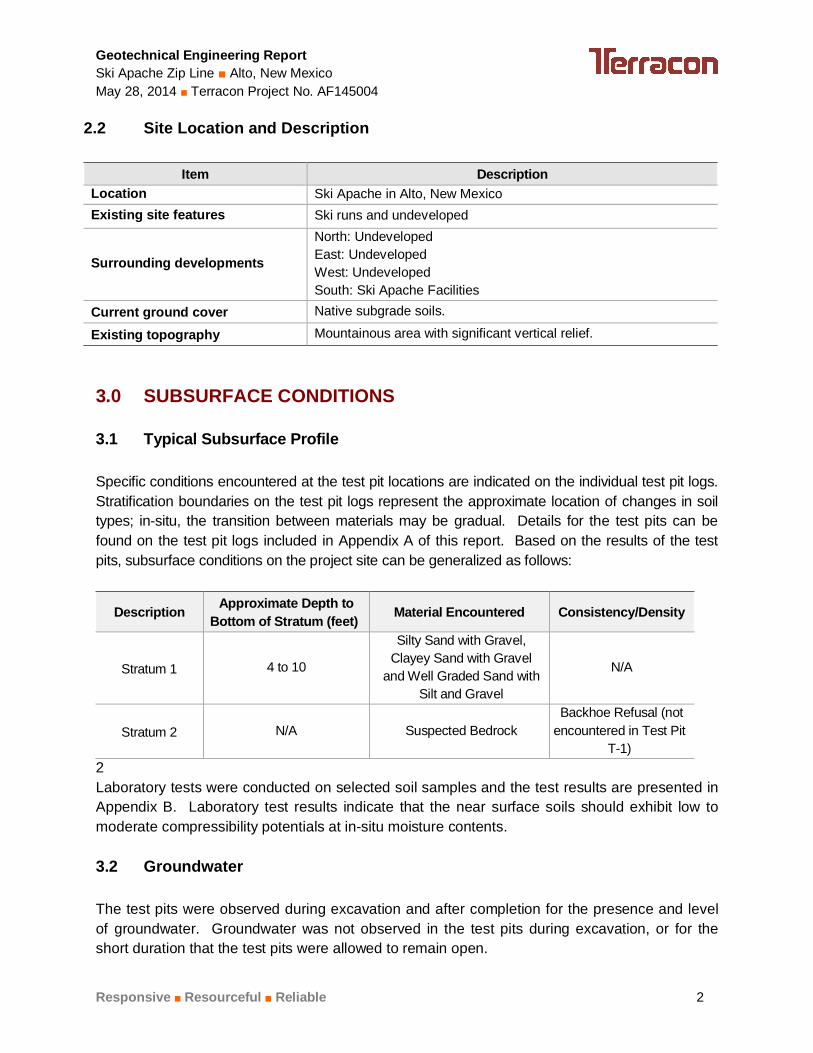
2.2 Site Location and Description
Item Description Location Ski Apache in Alto, New Mexico Existing site features Ski runs and undeveloped
Surrounding developments
North: Undeveloped East: Undeveloped West: Undeveloped South: Ski Apache Facilities
Current ground cover Native subgrade soils.
Existing topography Mountainous area with significant vertical relief. 3.0 SUBSURFACE CONDITIONS 3.1 Typical Subsurface Profile Specific conditions encountered at the test pit locations are indicated on the individual test pit logs. Stratification boundaries on the test pit logs represent the approximate location of changes in soil types; in-situ, the transition between materials may be gradual. Details for the test pits can be found on the test pit logs included in Appendix A of this report. Based on the results of the test pits, subsurface conditions on the project site can be generalized as follows:
Description Approximate Depth to Bottom of Stratum (feet) Material Encountered Consistency/Density
Stratum 1 4 to 10
Silty Sand with Gravel, Clayey Sand with Gravel
and Well Graded Sand with Silt and Gravel
N/A
Stratum 2 N/A Suspected Bedrock Backhoe Refusal (not
encountered in Test Pit T-1)
2 Laboratory tests were conducted on selected soil samples and the test results are presented in Appendix B. Laboratory test results indicate that the near surface soils should exhibit low to moderate compressibility potentials at in-situ moisture contents. 3.2 Groundwater The test pits were observed during excavation and after completion for the presence and level of groundwater. Groundwater was not observed in the test pits during excavation, or for the short duration that the test pits were allowed to remain open.

Geotechnical Engineering Report Ski Apache Zip Line Alto, New Mexico May 28, 2014 Terracon Project No. AF145004
Responsive Resourceful Reliable 3
4.0 RECOMMENDATIONS FOR DESIGN AND CONSTRUCTION 4.1 Geotechnical Considerations The site appears suitable for the proposed construction based upon geotechnical conditions encountered in the test pits. Based on the geotechnical engineering analyses, subsurface exploration and laboratory test results, it is our opinion that the proposed tower structures can be supported by the preferred mat foundations bearing on prepared native soils or engineered fill materials. The elevated decks can be supported by shallow spread footings on prepared native soils or engineered fill materials. Geotechnical engineering recommendations for foundation systems and other earth connected phases of the project are outlined below. The recommendations contained in this report are based upon the results of field and laboratory testing (which are presented in Appendices A and B), engineering analyses, and our current understanding of the proposed project. 4.2 Earthwork The following presents recommendations for site preparation, excavation, subgrade preparation and placement of engineered fills on the project. The recommendations presented for design and construction of earth supported elements including foundations are contingent upon following the recommendations outlined in this section. All grading for the structures should incorporate the limits plus a minimum pad extension of three feet beyond proposed foundation perimeters. Earthwork on the project should be observed and evaluated by Terracon. The evaluation of earthwork should include observation and testing of engineered fill, subgrade preparation, foundation bearing soils, and other geotechnical conditions exposed during the construction of the project. 4.2.1 Site Preparation Prior to construction or placing any fill, all vegetation (if applicable), and any otherwise unsuitable materials should be removed from the construction areas. Wet or dry material should either be removed, dried or moisture conditioned and compacted. Exposed areas which will receive fill or be constructed upon, once properly cleared, should be scarified to a minimum depth of 10 inches, conditioned to near optimum moisture content, and compacted.
Geotechnical Engineering Report Ski Apache Zip Line Alto, New Mexico May 28, 2014 Terracon Project No. AF145004
Responsive Resourceful Reliable 4
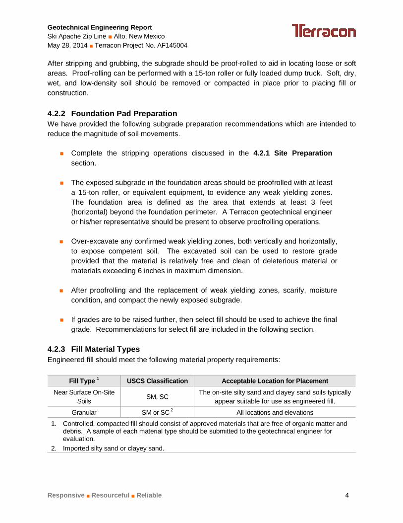
After stripping and grubbing, the subgrade should be proof-rolled to aid in locating loose or soft areas. Proof-rolling can be performed with a 15-ton roller or fully loaded dump truck. Soft, dry, wet, and low-density soil should be removed or compacted in place prior to placing fill or construction. 4.2.2 Foundation Pad Preparation We have provided the following subgrade preparation recommendations which are intended to reduce the magnitude of soil movements.
Complete the stripping operations discussed in the 4.2.1 Site Preparation section.
The exposed subgrade in the foundation areas should be proofrolled with at least a 15-ton roller, or equivalent equipment, to evidence any weak yielding zones. The foundation area is defined as the area that extends at least 3 feet (horizontal) beyond the foundation perimeter. A Terracon geotechnical engineer or his/her representative should be present to observe proofrolling operations.
Over-excavate any confirmed weak yielding zones, both vertically and horizontally,
to expose competent soil. The excavated soil can be used to restore grade provided that the material is relatively free and clean of deleterious material or materials exceeding 6 inches in maximum dimension.
After proofrolling and the replacement of weak yielding zones, scarify, moisture
condition, and compact the newly exposed subgrade.
If grades are to be raised further, then select fill should be used to achieve the final grade. Recommendations for select fill are included in the following section.
4.2.3 Fill Material Types Engineered fill should meet the following material property requirements:
Fill Type 1 USCS Classification Acceptable Location for Placement Near Surface On-Site
Soils SM, SC
The on-site silty sand and clayey sand soils typically appear suitable for use as engineered fill.
Granular SM or SC 2 All locations and elevations
1. Controlled, compacted fill should consist of approved materials that are free of organic matter and debris. A sample of each material type should be submitted to the geotechnical engineer for evaluation.
2. Imported silty sand or clayey sand.
Geotechnical Engineering Report Ski Apache Zip Line Alto, New Mexico May 28, 2014 Terracon Project No. AF145004
Responsive Resourceful Reliable 5
4.2.4 Fill Material Placement and Compaction Requirements Item Description
Fill Lift Thickness 10 inches or less in loose thickness
Minimum Compaction Requirements 1 95% of the materials maximum modified Proctor dry density (ASTM D 1557)
Moisture Content Within 2% of optimum moisture content value as determined by the modified Proctor test at the time of placement and compaction
1. We recommend that engineered fill be tested for moisture content and compaction during placement. Should the results of the in-place density tests indicate the specified moisture or compaction limits have not been met, the area represented by the test should be reworked and retested as required until the specified moisture and compaction requirements are achieved.
4.2.5 Grading and Drainage Positive drainage should be provided during construction and maintained throughout the life of the project. Infiltration of water into foundation excavations should be prevented during construction. Surface features which could retain water in areas adjacent to the structures should be sealed or eliminated. We recommend that protective slopes be provided with a minimum grade of approximately 5 percent for at least 10 feet from the foundation perimeters (where applicable). Backfill against foundations should be well compacted and free of all construction debris to reduce the possibility of moisture infiltration. 4.2.6 Earthwork Construction Considerations Although the exposed subgrade is anticipated to be relatively stable upon initial exposure, unstable subgrade conditions could develop during general construction operations, particularly if the soils are wetted and/or subjected to repetitive construction traffic. The use of light construction equipment would aid in reducing subgrade disturbance. The use of remotely operated equipment, such as a backhoe, would be beneficial to perform cuts and reduce subgrade disturbance. Should unstable subgrade conditions develop, stabilization measures will need to be employed. Upon completion of filling and grading, care should be taken to maintain the subgrade moisture content prior to construction of foundations. Construction traffic over the completed subgrade should be avoided to the extent practical. The site should also be graded to prevent ponding of surface water on the prepared subgrades or in excavations. If the subgrade should become desiccated, saturated, or disturbed, the affected material should be removed or these materials should be scarified, moisture conditioned, and recompacted prior to foundation construction. Temporary excavations will probably be required during grading operations. The grading contractor, by his contract, is usually responsible for designing and constructing stable, temporary excavations and should shore, slope or bench the sides of the excavations as required, to maintain stability of both the excavation sides and bottom. All excavations should
Geotechnical Engineering Report Ski Apache Zip Line Alto, New Mexico May 28, 2014 Terracon Project No. AF145004
Responsive Resourceful Reliable 6
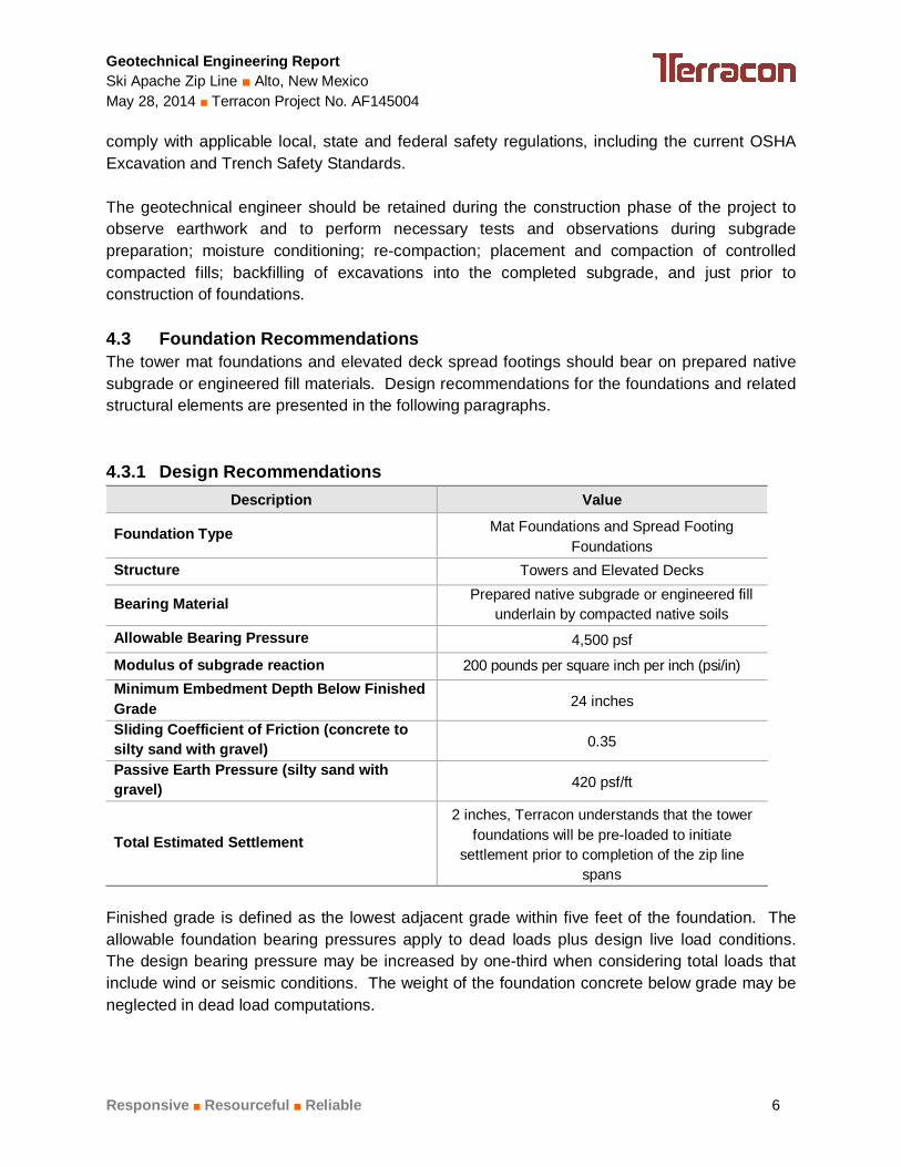
comply with applicable local, state and federal safety regulations, including the current OSHA Excavation and Trench Safety Standards. The geotechnical engineer should be retained during the construction phase of the project to observe earthwork and to perform necessary tests and observations during subgrade preparation; moisture conditioning; re-compaction; placement and compaction of controlled compacted fills; backfilling of excavations into the completed subgrade, and just prior to construction of foundations. 4.3 Foundation Recommendations The tower mat foundations and elevated deck spread footings should bear on prepared native subgrade or engineered fill materials. Design recommendations for the foundations and related structural elements are presented in the following paragraphs. 4.3.1 Design Recommendations
Description Value
Foundation Type Mat Foundations and Spread Footing Foundations
Structure Towers and Elevated Decks
Bearing Material Prepared native subgrade or engineered fill underlain by compacted native soils
Allowable Bearing Pressure 4,500 psf
Modulus of subgrade reaction 200 pounds per square inch per inch (psi/in) Minimum Embedment Depth Below Finished Grade 24 inches
Sliding Coefficient of Friction (concrete to silty sand with gravel) 0.35
Passive Earth Pressure (silty sand with gravel) 420 psf/ft
Total Estimated Settlement
2 inches, Terracon understands that the tower foundations will be pre-loaded to initiate
settlement prior to completion of the zip line spans
Finished grade is defined as the lowest adjacent grade within five feet of the foundation. The allowable foundation bearing pressures apply to dead loads plus design live load conditions. The design bearing pressure may be increased by one-third when considering total loads that include wind or seismic conditions. The weight of the foundation concrete below grade may be neglected in dead load computations.

Geotechnical Engineering Report Ski Apache Zip Line Alto, New Mexico May 28, 2014 Terracon Project No. AF145004
Responsive Resourceful Reliable 7
The foundation should be proportioned to reduce differential foundation movement. Proportioning on the basis of equal total settlement is recommended. Additional foundation movements could occur if water from any source infiltrates the foundation soils; therefore, proper drainage should be provided in the final design and during construction. The foundation should be reinforced as necessary to reduce the potential for distress caused by differential foundation movement. Foundation excavations and engineered fill placement should be observed by the geotechnical engineer. If the soil conditions encountered differ significantly from those presented in this report, supplemental recommendations will be required. 4.4 Seismic Considerations
Description Value 2009 International Building Code Site Classification (IBC) 1 C2
Site Latitude 33.3931 Site Longitude -105.7861
Spectral Response Accelerations SMs and SM1 SMs = FaSs and SM1 = FvS1
Site Class C - Fa = 1.2, Fv = 1.7
SMS Spectral Acceleration for a Short Period (0.2 sec) 0.337 g SM1 Spectral Acceleration for a 1-Second Period 0.148 g
SDs = 2/3 x SMs and SD1 = 2/3 x SM1 SDS Spectral Acceleration for a Short Period (0.2 sec) 0.225 g
SD1 Spectral Acceleration for a 1-Second Period 0.099 g 1 Note: In general accordance with the 2009 International Building Code, Table 1613.5.2. IBC Site Class is based on the average characteristics of the upper 100 feet of the subsurface profile. 2 Note: The 2009 International Building Code (IBC) requires a site soil profile determination extending to a depth of 100 feet for seismic site classification. The current scope does not include the required 100 foot soil profile determination. The test pits extending to a maximum depth of 10 feet, and this seismic site class definition considers that dense soil may be encountered below the maximum depth of the subsurface exploration. Additional exploration to deeper depths would be required to confirm the conditions below the current depth of exploration.
5.0 GENERAL COMMENTS Terracon should be retained to review the final design plans and specifications so comments can be made regarding interpretation and implementation of our geotechnical recommendations

Geotechnical Engineering Report Ski Apache Zip Line Alto, New Mexico May 28, 2014 Terracon Project No. AF145004
Responsive Resourceful Reliable 8
in the design and specifications. Terracon also should be retained to provide observation and testing services during grading, excavation, foundation construction and other earth-related construction phases of the project. The analysis and recommendations presented in this report are based upon the data obtained from the borings performed at the indicated locations and from other information discussed in this report. This report does not reflect variations that may occur between borings, across the site, or due to the modifying effects of construction or weather. The nature and extent of such variations may not become evident until during or after construction. If variations appear, we should be immediately notified so that further evaluation and supplemental recommendations can be provided. The scope of services for this project does not include either specifically or by implication any environmental or biological (e.g., mold, fungi, bacteria) assessment of the site or identification or prevention of pollutants, hazardous materials or conditions. If the owner is concerned about the potential for such contamination or pollution, other studies should be undertaken. This report has been prepared for the exclusive use of our client for specific application to the project discussed and has been prepared in accordance with generally accepted geotechnical engineering practices. No warranties, either express or implied, are intended or made. Site safety, excavation support, and dewatering requirements are the responsibility of others. In the event that changes in the nature, design, or location of the project as outlined in this report are planned, the conclusions and recommendations contained in this report shall not be considered valid unless Terracon reviews the changes and either verifies or modifies the conclusions of this report in writing.

APPENDIX A
FIELD EXPLORATION

SKI APACHE ZIP LINE 1286 SKI RUN ROAD ALTO, NEW MEXICO
SITE LOCATION MAP
Project Mngr: DB
Drawn By:
Checked By:
Approved By:
DB
JDC
JDC
Project No. AF145004
Scale
File No.
Date:
Not to Scale
Site Map
5/6/14
1640 Hickory Loop, Suite 105 Las Cruces, New Mexico 88005
575.527.1700 Fax: 575.527.1092
FIG No.
A-1
DIAGRAM IS FOR GENERAL LOCATION ONLY, AND IS NOT INTENDED FOR CONSTRUCTION PURPOSES.
Source: USGS 7.5-Minute Topographic Map “Nogal Peak, NM (1/1/2004) and Sierra Blanca Peak, NM (1/1/1982).”
N
Project Site
Ski Run Rd
SKI APACHE ZIP LINE 1286 SKI RUN ROAD ALTO, NEW MEXICO
TEST PIT LOCATION PLAN
Project Mngr: DB
Drawn By:
Checked By:
Approved By:
DB
JDC
JDC
Project No. AF145004
Scale
File No.
Date:
N.T.S
Test Pit Location
5/5/14
1640 Hickory Loop, Suite 105 Las Cruces, New Mexico 88005
575.527.1700 Fax: 575.527.1092
FIG No.
A-2
DIAGRAM IS FOR GENERAL LOCATION ONLY, AND IS NOT INTENDED FOR CONSTRUCTION PURPOSES.
Approximate Test Pit Locations
Source:
N
T-1
T-2
T-3 T-4

Geotechnical Engineering Report Ski Apache Zip Line Alto, New Mexico May 28, 2014 Terracon Project No. AF145004
Responsive Resourceful Reliable Exhibit A-3
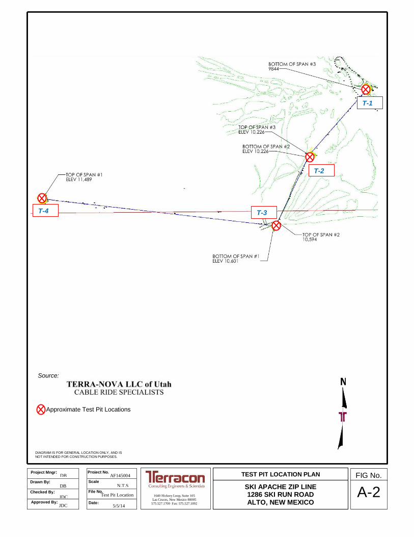
Field Exploration Description Four test pits were excavated at the site on May 1, 2014. The test pits were excavated to depths of about 4 to 10 feet below the ground surface at the approximate location shown on the attached Site Location Map and Boring Location Plan, Exhibit A-1 and A-2, respectively. Backhoe refusal was encountered in Test Pits T-2 through T-4 due to suspected bedrock. The test pits were located as follows:
Boring Location Depth (feet) T-1 Bottom of Span #3 10
T-2 Bottom of Span #2 4
T-3 Bottom of Span #1 6
T-4 Top of Span #1 7 The test pits were excavated with a backhoe. The test pit locations were staked in the field by the client. The accuracy of the test pit locations should only be assumed to the level implied by the method used. Lithologic logs of the test pits were recorded by the field engineer during the excavation operations. At selected intervals, samples of the subsurface materials were collected and placed in sample bags. Groundwater was not encountered in the test pits during the drilling operations.

7.0
10.0
SILTY SAND WITH GRAVEL (SM), black
CLAYEY SAND WITH GRAVEL (SC), yellowish-brown
Test Pit Terminated at 10 Feet
31
24
17
21
31-29-2
31-26-5
Stratification lines are approximate. In-situ, the transition may be gradual.
LOCATION
DEPTH
GR
AP
HIC
LO
G Bottom of Span #3
TH
IS B
OR
ING
LO
G IS
NO
T V
ALI
D IF
SE
PA
RA
TE
D F
RO
M O
RIG
INA
L R
EP
OR
T.
G
EO
SM
AR
T L
OG
-NO
WE
LL A
F14
5004
.GP
J
1286 SKI RUN ROAD ALTO, NEW MEXICOSITE:
PROJECT: SKI APACHE ZIP LINE
Page 1 of 1
Advancement Method:Backhoe
Abandonment Method:
1640 Hickory Loop, Suite 105Las Cruces, New Mexico
Notes:
Project No.: AF145004
Excavator:
Test Pit Started: 5/1/2014
TEST PIT LOG NO. T-1SKI APACHECLIENT:ALTO, NEW MEXICO
Operator:
Test Pit Completed: 5/1/2014
Exhibit: A-4
Per
cent
Fin
es
WA
TE
RC
ON
TE
NT
(%
)
DR
Y U
NIT
WE
IGH
T (
pcf)
ATTERBERGLIMITS
LL-PL-PI
DE
PT
H (
Ft.)
5
10S
AM
PLE
TY
PE
WA
TE
R L
EV
EL
OB
SE
RV
AT
ION
S
WATER LEVEL OBSERVATIONS

2.0
4.0
SILTY SAND WITH GRAVEL (SM), black
WELL GRADED SAND WITH SILT AND GRAVEL (SW-SM), yellowish-brown
Test pit refusal due to suspected bedrock at 4 Feet
67 NP
Stratification lines are approximate. In-situ, the transition may be gradual.
LOCATION
DEPTH
GR
AP
HIC
LO
G Top of Span #3/Bottomof Span #2
TH
IS B
OR
ING
LO
G IS
NO
T V
ALI
D IF
SE
PA
RA
TE
D F
RO
M O
RIG
INA
L R
EP
OR
T.
G
EO
SM
AR
T L
OG
-NO
WE
LL A
F14
5004
.GP
J
1286 SKI RUN ROAD ALTO, NEW MEXICOSITE:
PROJECT: SKI APACHE ZIP LINE
Page 1 of 1
Advancement Method:Backhoe
Abandonment Method:
1640 Hickory Loop, Suite 105Las Cruces, New Mexico
Notes:
Project No.: AF145004
Excavator:
Test Pit Started: 5/1/2014
TEST PIT LOG NO. T-2SKI APACHECLIENT:ALTO, NEW MEXICO
Operator:
Test Pit Completed: 5/1/2014
Exhibit: A-5
Per
cent
Fin
es
WA
TE
RC
ON
TE
NT
(%
)
DR
Y U
NIT
WE
IGH
T (
pcf)
ATTERBERGLIMITS
LL-PL-PI
DE
PT
H (
Ft.)
SA
MP
LE T
YP
E
WA
TE
R L
EV
EL
OB
SE
RV
AT
ION
S
WATER LEVEL OBSERVATIONS
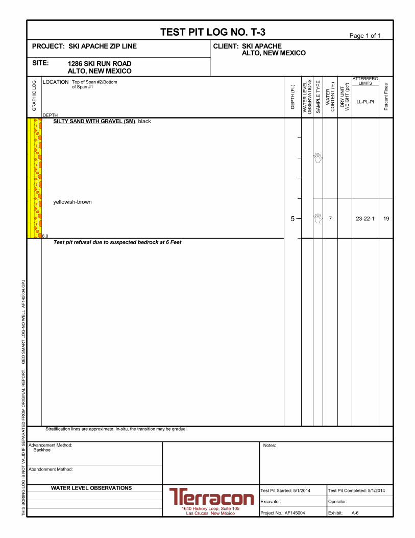
6.0
SILTY SAND WITH GRAVEL (SM), black
yellowish-brown
Test pit refusal due to suspected bedrock at 6 Feet
197 23-22-1
Stratification lines are approximate. In-situ, the transition may be gradual.
LOCATION
DEPTH
GR
AP
HIC
LO
G Top of Span #2/Bottomof Span #1
TH
IS B
OR
ING
LO
G IS
NO
T V
ALI
D IF
SE
PA
RA
TE
D F
RO
M O
RIG
INA
L R
EP
OR
T.
G
EO
SM
AR
T L
OG
-NO
WE
LL A
F14
5004
.GP
J
1286 SKI RUN ROAD ALTO, NEW MEXICOSITE:
PROJECT: SKI APACHE ZIP LINE
Page 1 of 1
Advancement Method:Backhoe
Abandonment Method:
1640 Hickory Loop, Suite 105Las Cruces, New Mexico
Notes:
Project No.: AF145004
Excavator:
Test Pit Started: 5/1/2014
TEST PIT LOG NO. T-3SKI APACHECLIENT:ALTO, NEW MEXICO
Operator:
Test Pit Completed: 5/1/2014
Exhibit: A-6
Per
cent
Fin
es
WA
TE
RC
ON
TE
NT
(%
)
DR
Y U
NIT
WE
IGH
T (
pcf)
ATTERBERGLIMITS
LL-PL-PI
DE
PT
H (
Ft.)
5
SA
MP
LE T
YP
E
WA
TE
R L
EV
EL
OB
SE
RV
AT
ION
S
WATER LEVEL OBSERVATIONS
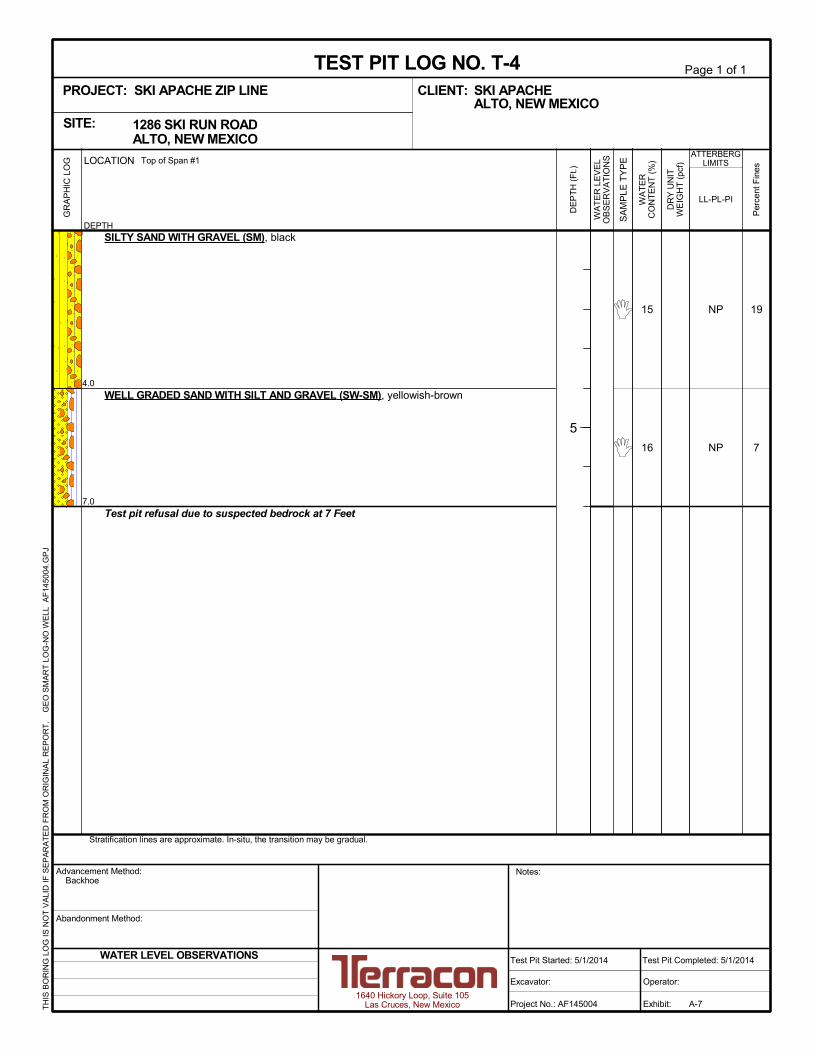
4.0
7.0
SILTY SAND WITH GRAVEL (SM), black
WELL GRADED SAND WITH SILT AND GRAVEL (SW-SM), yellowish-brown
Test pit refusal due to suspected bedrock at 7 Feet
19
7
15
16
NP
NP
Stratification lines are approximate. In-situ, the transition may be gradual.
LOCATION
DEPTH
GR
AP
HIC
LO
G Top of Span #1
TH
IS B
OR
ING
LO
G IS
NO
T V
ALI
D IF
SE
PA
RA
TE
D F
RO
M O
RIG
INA
L R
EP
OR
T.
G
EO
SM
AR
T L
OG
-NO
WE
LL A
F14
5004
.GP
J
1286 SKI RUN ROAD ALTO, NEW MEXICOSITE:
PROJECT: SKI APACHE ZIP LINE
Page 1 of 1
Advancement Method:Backhoe
Abandonment Method:
1640 Hickory Loop, Suite 105Las Cruces, New Mexico
Notes:
Project No.: AF145004
Excavator:
Test Pit Started: 5/1/2014
TEST PIT LOG NO. T-4SKI APACHECLIENT:ALTO, NEW MEXICO
Operator:
Test Pit Completed: 5/1/2014
Exhibit: A-7
Per
cent
Fin
es
WA
TE
RC
ON
TE
NT
(%
)
DR
Y U
NIT
WE
IGH
T (
pcf)
ATTERBERGLIMITS
LL-PL-PI
DE
PT
H (
Ft.)
5
SA
MP
LE T
YP
E
WA
TE
R L
EV
EL
OB
SE
RV
AT
ION
S
WATER LEVEL OBSERVATIONS
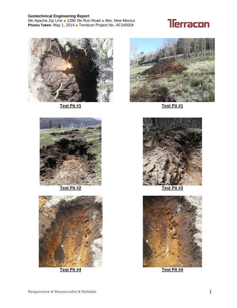
Geotechnical Engineering Report Ski Apache Zip Line 1286 Ski Run Road Alto, New Mexico Photos Taken: May 1, 2014 Terracon Project No. AF145004
Responsive Resourceful Reliable 1
Test Pit #1 Test Pit #1
Test Pit #2 Test Pit #3
Test Pit #4 Test Pit #4
APPENDIX B
LABORATORY TESTING
Geotechnical Engineering Report Ski Apache Zip Line Alto, New Mexico May 28, 2014 Terracon Project No. AF145004
Responsive Resourceful Reliable Exhibit B-1
Laboratory Testing Samples retrieved during the field exploration were taken to the laboratory for further observation by the project geotechnical engineer and were classified in accordance with the Unified Soil Classification System (USCS) described in Appendix A. At that time, the field descriptions were confirmed or modified as necessary and an applicable laboratory testing program was formulated to determine engineering properties of the subsurface materials. Laboratory tests were conducted on selected soil samples and the test results are presented in this appendix. The laboratory test results were used for the geotechnical engineering analyses, and the development of foundation and earthwork recommendations. Laboratory tests were performed in general accordance with the applicable ASTM, local or other accepted standards. Selected soil samples obtained from the site were tested for the following engineering properties:
Atterberg Limits Water Content Sieve Analysis

.
Sieve Size 1 1/2" 3/4" 3/8" #4 #10 #40 #100 #200
% Passing (Cumulative) 100% 87% 76% 67% 56% 43% 36% 31.4%Specification
% GRAVEL = 33% D85 = 17.3 D15 =% SAND = 35% D60 = 2.7 D10 =
% SILT & CLAY = 31% D50 = 1.0 CU =D30 = CC =
Project Name: Ski Apache Zip LineProject No.: AF145004
Sample Location: TP-1 at 0-7'Liquid Limit: 31 Plasticity Index: 2
USCS Classification: SMMaterial Description:
TEST SUMMARY
(575) 527-1700
TERRACON
1640 Hickory Loop, Suite 105Las Cruces, NM 88005
Silty Sand with Gravel
GRAIN SIZE - mm
GRAIN SIZE DISTRIBUTION GRAPH
0%
10%
20%
30%
40%
50%
60%
70%
80%
90%
100%
0.0010.010.11101001000
PER
CEN
T FI
NER
6 in
.
1.5
in.
#4
#200
.
Sieve Size 1 1/2" 3/4" 3/8" #4 #10 #40 #100 #200
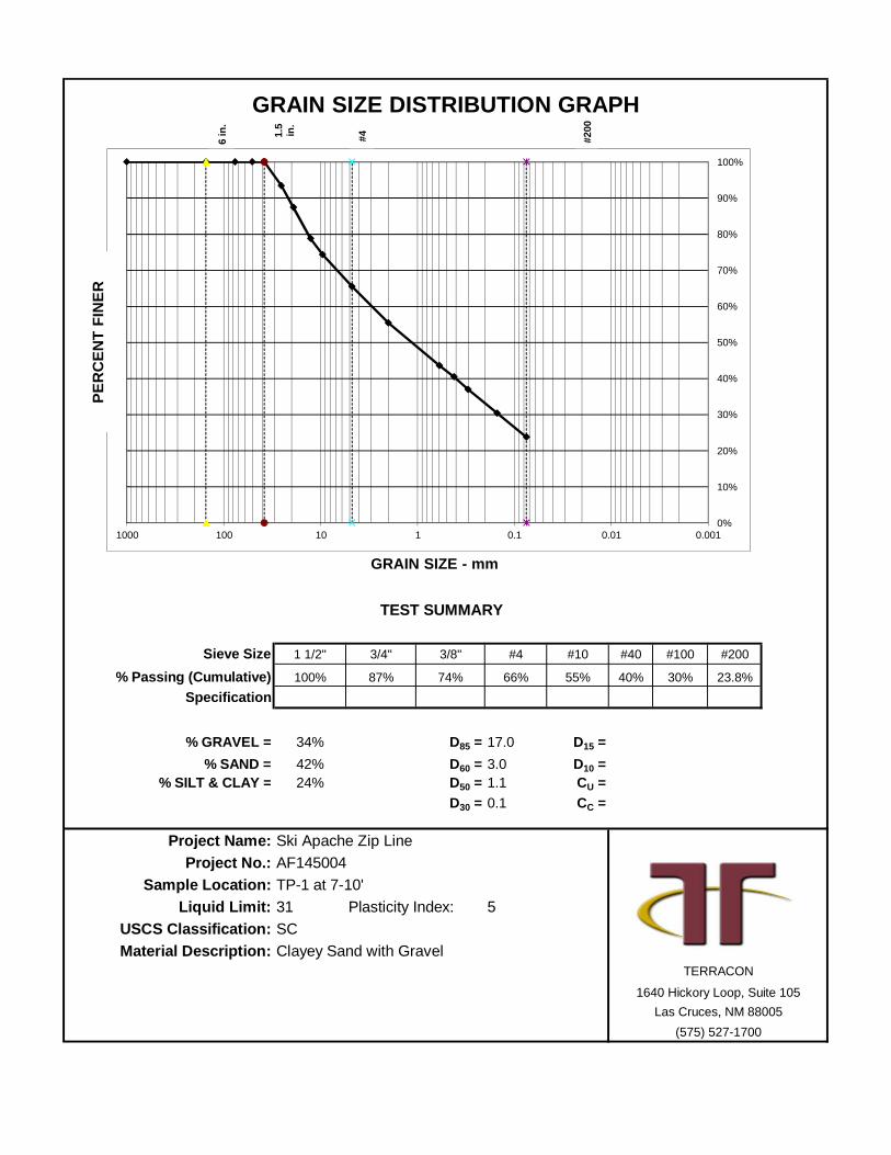
% Passing (Cumulative) 100% 87% 74% 66% 55% 40% 30% 23.8%Specification
% GRAVEL = 34% D85 = 17.0 D15 =% SAND = 42% D60 = 3.0 D10 =
% SILT & CLAY = 24% D50 = 1.1 CU =D30 = 0.1 CC =
Project Name: Ski Apache Zip LineProject No.: AF145004
Sample Location: TP-1 at 7-10'Liquid Limit: 31 Plasticity Index: 5
USCS Classification: SCMaterial Description:
TEST SUMMARY
(575) 527-1700
TERRACON
1640 Hickory Loop, Suite 105Las Cruces, NM 88005
Clayey Sand with Gravel
GRAIN SIZE - mm
GRAIN SIZE DISTRIBUTION GRAPH
0%
10%
20%
30%
40%
50%
60%
70%
80%
90%
100%
0.0010.010.11101001000
PER
CEN
T FI
NER
6 in
.
1.5
in.
#4
#200
.
Sieve Size 1 1/2" 3/4" 3/8" #4 #10 #40 #100 #200
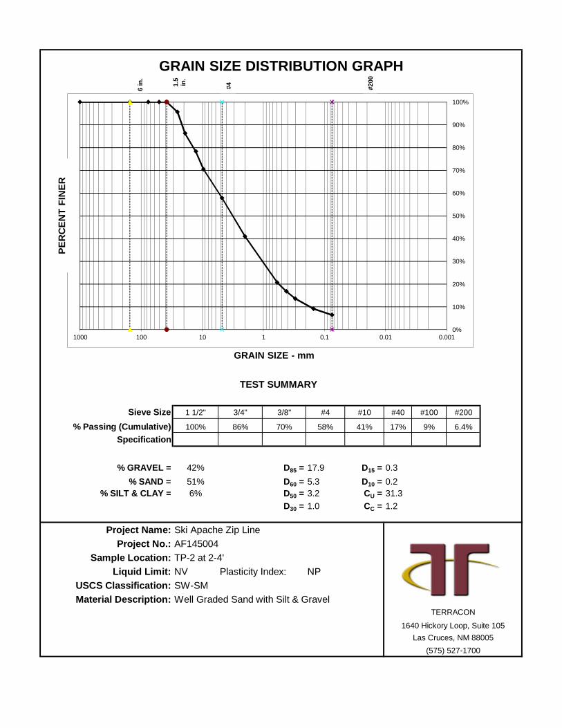
% Passing (Cumulative) 100% 86% 70% 58% 41% 17% 9% 6.4%Specification
% GRAVEL = 42% D85 = 17.9 D15 = 0.3% SAND = 51% D60 = 5.3 D10 = 0.2
% SILT & CLAY = 6% D50 = 3.2 CU = 31.3D30 = 1.0 CC = 1.2
Project Name: Ski Apache Zip LineProject No.: AF145004
Sample Location: TP-2 at 2-4'Liquid Limit: NV Plasticity Index: NP
USCS Classification: SW-SMMaterial Description:
TEST SUMMARY
(575) 527-1700
TERRACON
1640 Hickory Loop, Suite 105Las Cruces, NM 88005
Well Graded Sand with Silt & Gravel
GRAIN SIZE - mm
GRAIN SIZE DISTRIBUTION GRAPH
0%
10%
20%
30%
40%
50%
60%
70%
80%
90%
100%
0.0010.010.11101001000
PER
CEN
T FI
NER
6 in
.
1.5
in.
#4
#200

.
Sieve Size 1 1/2" 3/4" 3/8" #4 #10 #40 #100 #200
% Passing (Cumulative) 100% 87% 78% 68% 54% 33% 24% 19.4%Specification
% GRAVEL = 32% D85 = 15.7 D15 =% SAND = 49% D60 = 2.9 D10 =
% SILT & CLAY = 19% D50 = 1.5 CU =D30 = 0.3 CC =
Project Name: Ski Apache Zip LineProject No.: AF145004
Sample Location: TP-3 at 4-6'Liquid Limit: 23 Plasticity Index: 1
USCS Classification: SMMaterial Description:
TEST SUMMARY
(575) 527-1700
TERRACON
1640 Hickory Loop, Suite 105Las Cruces, NM 88005
Silty Sand with Gravel
GRAIN SIZE - mm
GRAIN SIZE DISTRIBUTION GRAPH
0%
10%
20%
30%
40%
50%
60%
70%
80%
90%
100%
0.0010.010.11101001000
PER
CEN
T FI
NER
6 in
.
1.5
in.
#4
#200
.
Sieve Size 1 1/2" 3/4" 3/8" #4 #10 #40 #100 #200
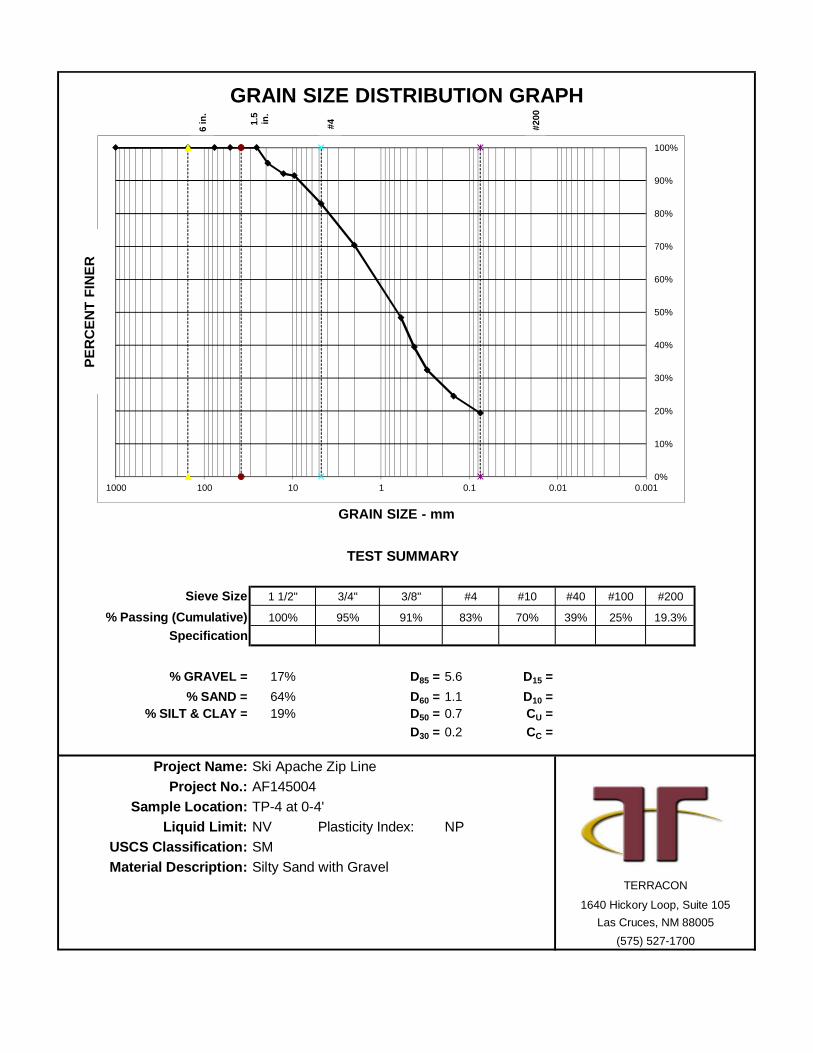
% Passing (Cumulative) 100% 95% 91% 83% 70% 39% 25% 19.3%Specification
% GRAVEL = 17% D85 = 5.6 D15 =% SAND = 64% D60 = 1.1 D10 =
% SILT & CLAY = 19% D50 = 0.7 CU =D30 = 0.2 CC =
Project Name: Ski Apache Zip LineProject No.: AF145004
Sample Location: TP-4 at 0-4'Liquid Limit: NV Plasticity Index: NP
USCS Classification: SMMaterial Description:
TEST SUMMARY
(575) 527-1700
TERRACON
1640 Hickory Loop, Suite 105Las Cruces, NM 88005
Silty Sand with Gravel
GRAIN SIZE - mm
GRAIN SIZE DISTRIBUTION GRAPH
0%
10%
20%
30%
40%
50%
60%
70%
80%
90%
100%
0.0010.010.11101001000
PER
CEN
T FI
NER
6 in
.
1.5
in.
#4
#200
.
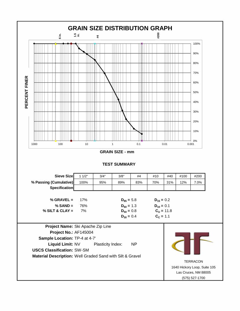
Sieve Size 1 1/2" 3/4" 3/8" #4 #10 #40 #100 #200
% Passing (Cumulative) 100% 95% 89% 83% 70% 31% 12% 7.0%Specification
% GRAVEL = 17% D85 = 5.8 D15 = 0.2% SAND = 76% D60 = 1.3 D10 = 0.1
% SILT & CLAY = 7% D50 = 0.8 CU = 11.8D30 = 0.4 CC = 1.1
Project Name: Ski Apache Zip LineProject No.: AF145004
Sample Location: TP-4 at 4-7'Liquid Limit: NV Plasticity Index: NP
USCS Classification: SW-SMMaterial Description:
TEST SUMMARY
(575) 527-1700
TERRACON
1640 Hickory Loop, Suite 105Las Cruces, NM 88005
Well Graded Sand with Silt & Gravel
GRAIN SIZE - mm
GRAIN SIZE DISTRIBUTION GRAPH
0%
10%
20%
30%
40%
50%
60%
70%
80%
90%
100%
0.0010.010.11101001000
PER
CEN
T FI
NER
6 in
.
1.5
in.
#4
#200

APPENDIX C
SUPPORTING DOCUMENTS

TraceWithModifier
Water Level Aftera Specified Period of Time
GRAIN SIZE TERMINOLOGYRELATIVE PROPORTIONS OF SAND AND GRAVEL
TraceWithModifier
Standard Penetration orN-Value
Blows/Ft.
Descriptive Term(Consistency)
Loose
Very Stiff
Exhibit C-1
Standard Penetration orN-Value
Blows/Ft.
Ring SamplerBlows/Ft.
Ring SamplerBlows/Ft.
Medium Dense
Dense
Very Dense
0 - 1 < 3
4 - 9 2 - 4 3 - 4
Medium-Stiff 5 - 9
30 - 50
WA
TE
R L
EV
EL
Auger
Shelby Tube
Ring Sampler
Grab Sample
8 - 15
Split Spoon
Macro Core
Rock Core
PLASTICITY DESCRIPTION
Term
< 1515 - 29> 30
Descriptive Term(s)of other constituents
Water InitiallyEncountered
Water Level After aSpecified Period of Time
Major Componentof Sample
Percent ofDry Weight
(More than 50% retained on No. 200 sieve.)Density determined by Standard Penetration Resistance
Includes gravels, sands and silts.
Hard
Very Loose 0 - 3 0 - 6 Very Soft
7 - 18 Soft
10 - 29 19 - 58
59 - 98 Stiff
less than 500
500 to 1,000
1,000 to 2,000
2,000 to 4,000
4,000 to 8,000> 99
LOCATION AND ELEVATION NOTES
SA
MP
LIN
G
FIE
LD
TE
ST
S
(HP)
(T)
(b/f)
(PID)
(OVA)
DESCRIPTION OF SYMBOLS AND ABBREVIATIONS
Descriptive Term(Density)
Non-plasticLowMediumHigh
BouldersCobblesGravelSandSilt or Clay
10 - 18
> 50 15 - 30 19 - 42
> 30 > 42
_
Hand Penetrometer
Torvane
Standard PenetrationTest (blows per foot)
Photo-Ionization Detector
Organic Vapor Analyzer
Water levels indicated on the soil boringlogs are the levels measured in theborehole at the times indicated.Groundwater level variations will occurover time. In low permeability soils,accurate determination of groundwaterlevels is not possible with short termwater level observations.
CONSISTENCY OF FINE-GRAINED SOILS
(50% or more passing the No. 200 sieve.)Consistency determined by laboratory shear strength testing, field
visual-manual procedures or standard penetration resistance
DESCRIPTIVE SOIL CLASSIFICATION
> 8,000
Unless otherwise noted, Latitude and Longitude are approximately determined using a hand-held GPS device. The accuracyof such devices is variable. Surface elevation data annotated with +/- indicates that no actual topographical survey wasconducted to confirm the surface elevation. Instead, the surface elevation was approximately determined from topographicmaps of the area.
Soil classification is based on the Unified Soil Classification System. Coarse Grained Soils have more than 50% of their dryweight retained on a #200 sieve; their principal descriptors are: boulders, cobbles, gravel or sand. Fine Grained Soils haveless than 50% of their dry weight retained on a #200 sieve; they are principally described as clays if they are plastic, andsilts if they are slightly plastic or non-plastic. Major constituents may be added as modifiers and minor constituents may beadded according to the relative proportions based on grain size. In addition to gradation, coarse-grained soils are definedon the basis of their in-place relative density and fine-grained soils on the basis of their consistency.
Plasticity Index
01 - 1011 - 30
> 30
RELATIVE PROPORTIONS OF FINES
Descriptive Term(s)of other constituents
Percent ofDry Weight
< 55 - 12> 12
No Recovery
RELATIVE DENSITY OF COARSE-GRAINED SOILS
Particle Size
Over 12 in. (300 mm)12 in. to 3 in. (300mm to 75mm)3 in. to #4 sieve (75mm to 4.75 mm)#4 to #200 sieve (4.75mm to 0.075mmPassing #200 sieve (0.075mm)
ST
RE
NG
TH
TE
RM
S Unconfined CompressiveStrength, Qu, psf
4 - 8
GENERAL NOTES

Exhibit C-2
UNIFIED SOIL CLASSIFICATION SYSTEM
Criteria for Assigning Group Symbols and Group Names Using Laboratory Tests A
Soil Classification
Group
Symbol Group Name
B
Coarse Grained Soils:
More than 50% retained
on No. 200 sieve
Gravels:
More than 50% of
coarse fraction retained
on No. 4 sieve
Clean Gravels:
Less than 5% fines C
Cu 4 and 1 Cc 3 E
GW Well-graded gravel F
Cu 4 and/or 1 Cc 3 E
GP Poorly graded gravel F
Gravels with Fines:
More than 12% fines C
Fines classify as ML or MH GM Silty gravel F,G,H
Fines classify as CL or CH GC Clayey gravel F,G,H
Sands:
50% or more of coarse
fraction passes No. 4
sieve
Clean Sands:
Less than 5% fines D
Cu 6 and 1 Cc 3 E
SW Well-graded sand I
Cu 6 and/or 1 Cc 3 E
SP Poorly graded sand I
Sands with Fines:
More than 12% fines D
Fines classify as ML or MH SM Silty sand G,H,I
Fines classify as CL or CH SC Clayey sand G,H,I
Fine-Grained Soils:
50% or more passes the
No. 200 sieve
Silts and Clays:
Liquid limit less than 50
Inorganic: PI 7 and plots on or above “A” line
J CL Lean clay
K,L,M
PI 4 or plots below “A” line J ML Silt
K,L,M
Organic: Liquid limit - oven dried
0.75 OL Organic clay
K,L,M,N
Liquid limit - not dried Organic silt K,L,M,O
Silts and Clays:
Liquid limit 50 or more
Inorganic: PI plots on or above “A” line CH Fat clay
K,L,M
PI plots below “A” line MH Elastic Silt K,L,M
Organic: Liquid limit - oven dried
0.75 OH Organic clay
K,L,M,P
Liquid limit - not dried Organic silt K,L,M,Q
Highly organic soils: Primarily organic matter, dark in color, and organic odor PT Peat
A Based on the material passing the 3-inch (75-mm) sieve
B If field sample contained cobbles or boulders, or both, add “with cobbles
or boulders, or both” to group name. C
Gravels with 5 to 12% fines require dual symbols: GW-GM well-graded
gravel with silt, GW-GC well-graded gravel with clay, GP-GM poorly
graded gravel with silt, GP-GC poorly graded gravel with clay. D
Sands with 5 to 12% fines require dual symbols: SW-SM well-graded
sand with silt, SW-SC well-graded sand with clay, SP-SM poorly graded
sand with silt, SP-SC poorly graded sand with clay
E Cu = D60/D10 Cc =
6010
2
30
DxD
)(D
F If soil contains 15% sand, add “with sand” to group name.
G If fines classify as CL-ML, use dual symbol GC-GM, or SC-SM.
H If fines are organic, add “with organic fines” to group name.
I If soil contains 15% gravel, add “with gravel” to group name.
J If Atterberg limits plot in shaded area, soil is a CL-ML, silty clay.
K If soil contains 15 to 29% plus No. 200, add “with sand” or “with gravel,”
whichever is predominant. L
If soil contains 30% plus No. 200 predominantly sand, add “sandy” to
group name. M
If soil contains 30% plus No. 200, predominantly gravel, add
“gravelly” to group name. N
PI 4 and plots on or above “A” line. O
PI 4 or plots below “A” line. P
PI plots on or above “A” line. Q
PI plots below “A” line.
Top Related