


Languages
Pages
Legal


*EP010* EP010 Rev.: 09 August, 2011
Genesis Standard
(GR) Series
Submittal Data
Models GRH/V 006 - 06050Hz - R407C
English Language/S-I Units
Rev.: 09 August, 2011
ClimateMaster works continually to improve its products. As a result, the design and specifications of each product at the time of order may be changed without notice and may not be as described herein. Please contact ClimateMaster's Customer Service Department at +1-405-745-6000 for specific information on the current design and specifications. Statements and other information contained herein are not express warranties and do not form the basis of any bargain between the parties, but are merely ClimateMaster's opinion or commendation of its products. The latest version of this document is available at climatemaster.com.
Submittal Data - S-i unitS
Unit Designation:
Job Name:
Architect:
Engineer:
Contractor:
Performance Data
Cooling Capacity: kW
EER:
Heating Capacity: kW
COP:
Ambient Air Temp: °C
Entering Water Temp (Clg): °C
Entering Air Temp (Clg): °C
Entering Water Temp (Htg): °C
Entering Air Temp (Htg): °C
Airflow: l/s
Fan Speed or Motor/RPM/Turns:
Operating Weight: (kg)
electrical Data
Power Supply: Volts Phase Hz
Minimum Circuit Ampacity:
Maximum Overcurrent Protection:

ClimateMaster works continually to improve its products. As a result, the design and specifications of each product at the time of order may be changed without notice and may not be as described herein. Please contact ClimateMaster's Customer Service Department at +1-405-745-6000 for specific information on the current design and specifications. Statements and other information contained herein are not express warranties and do not form the basis of any bargain between the parties, but are merely ClimateMaster's opinion or commendation of its products. The latest version of this document is available at climatemaster.com.
Page ______ of ______Rev.: 09 August, 2011EP010 - 2
GR Series 50Hz - R407C Submittal Data Eng/S-I
Table of Contents
*Page Number
GR Series Nomenclature 3
Performance Data - AHRI/ASHRAE/ISO 13256-1 4
Performance Data Selection Notes 5
Performance Data - GRH006 6
Performance Data - GRH/V 009 7
Performance Data - GRH/V 012 8
Performance Data - GRH/V 015 9
Performance Data - GRH/V 019 10
Performance Data - GRH/V 024 11
Performance Data - GRH/V 030 12
Performance Data - GRH/V 036 13
Performance Data - GRH/V 042 14
Performance Data - GRH/V 048 15
Performance Data - GRH/V 060 16
Performance Data Correction Tables 17
Antifreeze Correction Tables 18
Blower Performance Data 19
Physical Data 20
GR - Horizontal Dimensional Data 21
GR - Vertical Upflow Dimensional Data 23
Corner Weights 25
Electrical Data 26
GR Series Wiring Diagram Matrix 27
Typical Wiring Diagram Single Phase GR Units With CXM Controller 28
Typical Wiring Diagram Single Phase GR Units With DXM Controller 29
Typical Wiring Diagram Single Phase GR Units With CXM & MPC Controller 30
Typical Wiring Diagram Three Phase GR Units With CXM Controller 31
Typical Wiring Diagram Three Phase GR Units With DXM Controller 32
Genesis Standard (GR) Series Engineering Specifications 33
Revision History 40
*Document page number is shown next to part number (e.g. EP010 - 3 = page 3). Since not all pages are typically used in the submittals process, the page number in the lower right corner can still be used (page ____of_____).

ClimateMaster works continually to improve its products. As a result, the design and specifications of each product at the time of order may be changed without notice and may not be as described herein. Please contact ClimateMaster's Customer Service Department at +1-405-745-6000 for specific information on the current design and specifications. Statements and other information contained herein are not express warranties and do not form the basis of any bargain between the parties, but are merely ClimateMaster's opinion or commendation of its products. The latest version of this document is available at climatemaster.com.
Page ______ of ______Rev.: 09 August, 2011EP010 - 3
GR Series 50Hz - R407C Submittal Data Eng/S-I
GR Series Nomenclature
B = Current Revision For 019 - 036C = Current Revision For 015
G R H B0 3 6 CT 3 0 C L B S1 2 3 4 5 6 7 8 9 10 11 12 13 14 15
GR = Genesis ReciprocatingModel Type
H = HorizontalConfiguration
V = Vertical
006 (GRH Only)Unit Size
009012015019024030036042048060
Revision LevelA = Current Revision For Sizes 006 - 012 & 042 - 060
Voltage
Controls
1 = Extended RangeCabinet Insulation2 = Extended Range w/UltraQuiet
Water Circuit Options
Heat Exchanger Options
L = Left ReturnReturn AirR = Right Return
B = Back Discharge, Horizontal OnlySupply AirY = Back Discharge, High Static (GRH048)T = Top Discharge, Vertical OnlyV = Top Discharge, High Static (GRV048)S = Straight Discharge, Horizontal OnlyZ = Straight Discharge, High Static (GRH048)
Standard
3 = Standard Range4 = Standard Range w/UltraQuiet
0 = None8 = Auto Flow Regulator 2.5 GPM/Ton9 = Auto Flow Regulator 3 GPM/Ton
S = Standard
StandardLON DDC
"S" & "T" Voltage Only - CE MarkCXM DXM
FH
GJ
MPC DDC T U
T = 220-240/50/1 - R407CS = 380-420/50/3 - R407C
StandardMotorized Valve
Non Coated Air Coil Coated Air CoilCopper Cupro-Nickel Copper Cupro-Nickel
CT
NS
AU
JW

ClimateMaster works continually to improve its products. As a result, the design and specifications of each product at the time of order may be changed without notice and may not be as described herein. Please contact ClimateMaster's Customer Service Department at +1-405-745-6000 for specific information on the current design and specifications. Statements and other information contained herein are not express warranties and do not form the basis of any bargain between the parties, but are merely ClimateMaster's opinion or commendation of its products. The latest version of this document is available at climatemaster.com.
Page ______ of ______Rev.: 09 August, 2011EP010 - 4
GR Series 50Hz - R407C Submittal Data Eng/S-I
Performance DataAHRI/ASHRAE/ISO 13256-1
Model
Water Loop Heat Pump Ground Water Heat Pump Ground Loop Heat Pump
Cooling 30°C Heating 20°C Cooling 15°C Heating 10°C Cooling 25°C Heating 0°C
Capacity kW
EER W/W
Capacity kW
COP W/W
Capacity kW
EER W/W
Capacity kW
COP W/W
Capacity kW
EER W/W
Capacity kW
COP W/W
GRH006 1.50 3.3 1.80 3.9 1.80 5.3 1.50 3.4 1.60 3.9 1.20 3.0
GRH/V 009 2.10 4.0 2.40 4.2 2.50 6.3 2.00 3.8 2.20 4.7 1.60 3.3
GRH/V 012 2.50 3.1 3.40 3.7 3.10 4.8 2.80 3.4 2.70 3.6 2.20 3.0
GRH/V 015 3.90 4.6 3.80 4.7 4.50 6.8 3.10 4.2 4.10 5.3 2.60 3.7
GRH/V 019 4.90 3.3 6.10 4.0 5.90 4.8 4.80 3.6 5.30 3.8 3.60 3.1
GRH/V 024 5.70 3.4 7.00 4.0 6.80 5.0 5.70 3.7 6.10 3.9 4.40 3.3
GRH/V 030 6.40 3.3 7.90 4.2 7.40 4.9 6.40 3.7 6.80 3.8 5.10 3.2
GRH/V 036 8.00 3.3 10.60 4.0 9.30 4.6 8.70 3.7 8.50 3.7 6.80 3.3
GRH/V 042 9.90 3.7 11.30 4.4 12.20 5.8 9.50 4.0 10.80 4.4 7.50 3.6
GRH/V 048 11.40 3.6 14.30 4.1 13.10 5.2 11.40 3.7 12.00 4.1 8.40 3.4
GRH/V 060 13.70 3.4 16.80 4.3 15.90 5.2 13.80 3.8 14.50 4.0 11.20 3.3
Cooling capacities based upon 27°C DB, 19°C WB entering air temperatureHeating capacities based upon 20°C DB, 15°C WB entering air temperatureAll air flow is rated on high speedAll ratings based upon operation at lower voltage of dual voltage rated units

ClimateMaster works continually to improve its products. As a result, the design and specifications of each product at the time of order may be changed without notice and may not be as described herein. Please contact ClimateMaster's Customer Service Department at +1-405-745-6000 for specific information on the current design and specifications. Statements and other information contained herein are not express warranties and do not form the basis of any bargain between the parties, but are merely ClimateMaster's opinion or commendation of its products. The latest version of this document is available at climatemaster.com.
Page ______ of ______Rev.: 09 August, 2011EP010 - 5
GR Series 50Hz - R407C Submittal Data Eng/S-I
Performance DataSelection Notes
For operation in the shaded area when water is used in lieu of an antifreeze solution, the LWT (Leaving Water Temperature) must be calculated. Flow must be maintained to a level such that the LWT is maintained above 5°C when the JW3 jumper is not clipped (see example below). This is due to the potential of the refrigerant temperature being as low as 0°C with 5°C LWT, which may lead to a nuisance cutout due to the activation of the Low Temperature Protection. JW3 should never be clipped for standard range equipment or systems without antifreeze.
Example:
At 10°C EWT (Entering Water Temperature) and 0.284 l/s (minimum flow rate), a GR036 unit has a HE of 6.1 kW. To calculate LWT, rearrange the formula for HE as follows:
HE = TD x Flow x 4.18 where HE = Heat of Extraction (kW); TD = temperature difference (EWT - LWT); andFlow = Water Flow Rate in l/s
TD = HE / (l/s x 4.18)TD = 6.1 / (0.284 x 4.18)TD = 5.1°CLWT = EWT - TDLWT = 10 – 5.1 = 4.9°C
In this example, operating at minimum flow rate when the EWT is 10°C could cause a nuisance cutout. Therefore, the flow rate should be increased to maintain a LWT of at least 5°C. This example is typical of open loop systems with EWT at or below 10°C. The middle flow rate (0.429 l/s) provides a TD of 3.4°C, which maintains a LWT of 6.7°C, well above the minimum.
437 l/s Nominal Airflow Performance capacities shown in thousands of Watts.
EWT °C
Flowl/s
WPDkPa
COOLING - EAT 27/19 °C HEATING - EAT 20°C
TC kW
SC kW
S/TPower
kWHR kW
EER W/W
HC kW
Power kW
HE kW
LAT °C
COP W/W
-50.284 6.5
Operation not RecommendedOperation not Recommended
0.429 15.1 5.99 2.07 3.9 31.4 2.890.568 26.3 6.11 2.08 4.0 31.6 2.94
00.284 6.3 9.89 6.85 0.69 1.81 11.7 5.47 6.67 2.15 4.5 32.6 3.110.429 14.6 10.10 6.95 0.69 1.73 11.8 5.82 6.92 2.18 4.7 33.1 3.180.568 25.6 10.22 7.00 0.69 1.70 11.9 6.02 7.04 2.19 4.8 33.3 3.21
50.284 6.2 9.58 6.70 0.70 1.93 11.5 4.95 7.55 2.27 5.3 34.3 3.330.429 14.3 9.78 6.81 0.70 1.84 11.6 5.31 7.84 2.31 5.5 34.9 3.400.568 25.0 9.90 6.84 0.69 1.81 11.7 5.46 7.99 2.33 5.7 35.1 3.43
100.284 6.0 9.26 6.59 0.71 2.06 11.3 4.50 8.47 2.40 6.1 36.1 3.530.429 13.8 9.47 6.65 0.70 1.97 11.4 4.81 8.79 2.45 6.3 36.7 3.590.568 24.2 9.58 6.71 0.70 1.93 11.5 4.97 8.97 2.48 6.5 37.0 3.62
150.284 5.7 8.92 6.46 0.72 2.19 11.1 4.06 9.37 2.54 6.8 37.8 3.680.429 13.5 9.15 6.55 0.72 2.11 11.3 4.33 9.74 2.60 7.1 38.5 3.740.568 23.7 9.24 6.58 0.71 2.07 11.3 4.48 9.94 2.63 7.3 38.8 3.78
200.284 5.7 8.53 6.38 0.75 2.35 10.9 3.64 10.29 2.69 7.6 39.5 3.830.429 13.0 8.79 6.44 0.73 2.25 11.0 3.91 10.69 2.75 7.9 40.3 3.890.568 22.9 8.90 6.47 0.73 2.21 11.1 4.03 10.92 2.78 8.1 40.7 3.93
250.284 5.5 8.07 6.28 0.78 2.49 10.6 3.24 11.21 2.82 8.4 41.2 3.980.429 12.6 8.36 6.34 0.76 2.40 10.8 3.48 11.66 2.88 8.8 42.1 4.050.568 22.1 8.49 6.37 0.75 2.36 10.9 3.60 11.90 2.91 9.0 42.5 4.09
300.284 5.3 7.59 6.17 0.81 2.64 10.2 2.88 12.28 3.06 9.2 43.3 4.010.429 12.2 7.88 6.23 0.79 2.55 10.4 3.09 12.77 3.03 9.7 44.2 4.210.568 21.5 8.03 6.26 0.78 2.51 10.5 3.20 13.03 3.06 10.0 44.7 4.26
350.284 5.1 6.98 6.02 0.86 2.79 9.8 2.50
Operation not Recommended
0.429 11.8 7.31 6.11 0.84 2.71 10.0 2.700.568 20.8 7.47 6.14 0.82 2.67 10.1 2.80
400.284 5.0 6.30 5.80 0.92 2.95 9.2 2.140.429 11.4 6.66 5.94 0.89 2.86 9.5 2.330.568 20.1 6.85 5.98 0.87 2.82 9.7 2.43
450.284 4.8 6.30 5.78 0.92 3.16 9.5 1.990.429 11.1 6.65 5.87 0.88 3.07 9.7 2.160.568 19.6 6.82 5.90 0.86 3.03 9.9 2.25
Interpolation is permissible; extrapolation is not. All entering air conditions are 27°C DB and 19°C WB in cooling and 20°C DB in heating All performance data is based upon the lower voltage of dual voltage rated units Operation below 15°C EWT requires optional insulated water circuit Operation below 5°C EWT is based on 15% antifreeze solution. See performance correction tables for operating conditions other than those listed above. Table does not reflect fan or pump power ISO correctionsGray shaded area refers to calculations required to determine if heating water flow rate is sufficient for non-antifreeze systems.

ClimateMaster works continually to improve its products. As a result, the design and specifications of each product at the time of order may be changed without notice and may not be as described herein. Please contact ClimateMaster's Customer Service Department at +1-405-745-6000 for specific information on the current design and specifications. Statements and other information contained herein are not express warranties and do not form the basis of any bargain between the parties, but are merely ClimateMaster's opinion or commendation of its products. The latest version of this document is available at climatemaster.com.
Page ______ of ______Rev.: 09 August, 2011EP010 - 6
GR Series 50Hz - R407C Submittal Data Eng/S-I
Performance DataGRH006
81 l/s Nominal Airflow Performance capacities shown in thousands of Watts.
EWT °C
Flowl/s
WPDkPa
COOLING - EAT 27/19 °C HEATING - EAT 20°C
TC kW
SC kW
S/TPower
kWHR kW
EER W/W
HC kW
Power kW
HE kW
LAT °C
COP W/W
-5
0.050 4.1Operation not Recommended
Operation not Recommended0.069 6.9 1.14 0.40 0.7 31.6 2.830.095 10.7 1.16 0.40 0.8 31.8 2.88
0
0.050 3.9 2.01 1.35 0.67 0.30 2.3 6.59 1.20 0.41 0.8 32.2 2.890.069 6.8 2.06 1.37 0.66 0.29 2.4 7.02 1.23 0.41 0.8 32.5 2.960.095 10.4 2.09 1.37 0.66 0.28 2.4 7.37 1.23 0.41 0.8 32.6 2.97
5
0.050 3.9 1.93 1.35 0.70 0.32 2.2 5.94 1.30 0.43 0.9 33.3 3.030.069 6.5 1.98 1.35 0.68 0.31 2.3 6.33 1.34 0.43 0.9 33.6 3.090.095 10.1 2.01 1.35 0.67 0.30 2.3 6.65 1.37 0.43 0.9 33.9 3.16
10
0.050 3.9 1.85 1.32 0.71 0.36 2.2 5.13 1.44 0.44 1.0 34.7 3.260.069 6.3 1.88 1.32 0.70 0.34 2.2 5.52 1.49 0.45 1.0 35.2 3.320.095 9.9 1.93 1.35 0.70 0.33 2.3 5.86 1.52 0.45 1.1 35.5 3.39
15
0.050 3.6 1.74 1.27 0.73 0.39 2.1 4.50 1.59 0.46 1.1 36.3 3.480.069 6.3 1.80 1.29 0.72 0.37 2.2 4.90 1.65 0.47 1.2 36.9 3.530.095 9.6 1.83 1.30 0.71 0.36 2.2 5.12 1.68 0.47 1.2 37.2 3.59
20
0.050 3.6 1.64 1.24 0.76 0.42 2.1 3.88 1.75 0.48 1.3 37.9 3.680.069 6.0 1.69 1.24 0.73 0.40 2.1 4.21 1.81 0.48 1.3 38.5 3.790.095 9.3 1.72 1.27 0.73 0.39 2.1 4.40 1.84 0.49 1.4 38.8 3.79
25
0.050 3.4 1.53 1.19 0.78 0.46 2.0 3.34 1.89 0.49 1.4 39.3 3.880.069 5.8 1.59 1.21 0.76 0.44 2.0 3.63 1.95 0.49 1.5 39.9 3.950.095 9.1 1.62 1.22 0.75 0.43 2.1 3.78 2.00 0.50 1.5 40.4 4.02
30
0.050 3.3 1.42 1.14 0.80 0.49 1.9 2.87 2.06 0.51 1.6 41.1 4.020.069 5.7 1.48 1.17 0.79 0.47 2.0 3.12 2.12 0.51 1.6 41.7 4.190.095 8.7 1.51 1.17 0.77 0.46 2.0 3.26 2.18 0.51 1.7 42.3 4.25
35
0.050 3.3 1.29 1.08 0.84 0.52 1.8 2.46
Operation not Recommended
0.069 5.5 1.35 1.11 0.83 0.51 1.9 2.640.095 8.5 1.39 1.11 0.80 0.50 1.9 2.78
40
0.050 3.2 1.18 1.03 0.87 0.55 1.7 2.150.069 5.3 1.23 1.05 0.85 0.54 1.8 2.270.095 8.3 1.27 1.06 0.83 0.53 1.8 2.39
45
0.050 3.1 1.15 1.02 0.89 0.61 1.8 1.870.069 5.2 1.20 1.05 0.87 0.60 1.8 2.020.095 8.0 1.24 1.05 0.85 0.59 1.8 2.11
Interpolation is permissible; extrapolation is not. All entering air conditions are 27°C DB and 19°C WB in cooling and 20°C DB in heating All performance data is based upon the lower voltage of dual voltage rated units Operation below 15°C EWT requires optional insulated water circuit Operation below 5°C EWT is based on 15% antifreeze solution. See performance correction tables for operating conditions other than those listed above. Table does not reflect fan or pump power ISO correctionsGray shaded area refers to calculations required to determine if heating water flow rate is sufficient for non-antifreeze systems.

ClimateMaster works continually to improve its products. As a result, the design and specifications of each product at the time of order may be changed without notice and may not be as described herein. Please contact ClimateMaster's Customer Service Department at +1-405-745-6000 for specific information on the current design and specifications. Statements and other information contained herein are not express warranties and do not form the basis of any bargain between the parties, but are merely ClimateMaster's opinion or commendation of its products. The latest version of this document is available at climatemaster.com.
Page ______ of ______Rev.: 09 August, 2011EP010 - 7
GR Series 50Hz - R407C Submittal Data Eng/S-I
113 l/s Nominal Airflow Performance capacities shown in thousands of Watts.
EWT °C
Flowl/s
WPDkPa
COOLING - EAT 27/19 °C HEATING - EAT 20°C
TC kW
SC kW
S/TPower
kWHR kW
EER W/W
HC kW
Power kW
HE kW
LAT °C
COP W/W
-5
0.069 8.6Operation not Recommended
Operation not Recommended0.107 17.2 1.51 0.49 1.0 31.1 3.060.139 24.5 1.51 0.50 1.0 31.1 3.04
0
0.069 8.3 2.78 1.66 0.60 0.42 3.2 6.57 1.59 0.50 1.1 31.7 3.160.107 16.7 2.87 1.69 0.59 0.38 3.3 7.52 1.65 0.51 1.1 32.1 3.270.139 23.8 2.91 1.69 0.58 0.37 3.3 7.86 1.66 0.51 1.1 32.2 3.23
5
0.069 8.1 2.65 1.64 0.62 0.49 3.1 5.44 1.78 0.52 1.3 33.1 3.400.107 16.4 2.74 1.64 0.60 0.44 3.2 6.27 1.84 0.53 1.3 33.5 3.460.139 23.3 2.80 1.66 0.59 0.42 3.2 6.71 1.87 0.53 1.3 33.7 3.51
10
0.069 7.8 2.52 1.58 0.63 0.56 3.1 4.50 1.96 0.55 1.4 34.4 3.570.107 15.8 2.61 1.61 0.62 0.50 3.1 5.22 2.05 0.55 1.5 35.1 3.730.139 22.7 2.67 1.61 0.60 0.48 3.1 5.56 2.08 0.56 1.5 35.3 3.72
15
0.069 7.5 2.36 1.53 0.65 0.66 3.0 3.58 2.17 0.57 1.6 36.0 3.830.107 15.3 2.48 1.56 0.63 0.58 3.1 4.26 2.26 0.58 1.7 36.6 3.920.139 21.9 2.51 1.59 0.63 0.56 3.1 4.47 2.29 0.59 1.7 36.8 3.90
20
0.069 7.2 2.20 1.48 0.67 0.77 3.0 2.85 2.39 0.59 1.8 37.5 4.020.107 15.0 2.32 1.53 0.66 0.69 3.0 3.38 2.47 0.60 1.9 38.2 4.010.139 21.3 2.37 1.54 0.65 0.66 3.0 3.61 2.50 0.61 1.9 38.4 4.13
25
0.069 7.2 2.05 1.42 0.70 0.90 3.0 2.26 2.58 0.61 2.0 38.9 4.200.107 14.5 2.16 1.46 0.68 0.81 3.0 2.68 2.66 0.62 2.0 39.6 4.270.139 20.6 2.22 1.48 0.67 0.77 3.0 2.88 2.71 0.63 2.1 39.9 4.30
30
0.069 6.9 1.88 1.34 0.71 1.06 2.9 1.78 2.81 0.65 2.2 40.6 4.300.107 14.0 2.01 1.40 0.70 0.95 3.0 2.12 2.90 0.65 2.2 41.3 4.460.139 20.0 2.06 1.43 0.70 0.90 3.0 2.29 2.96 0.65 2.3 41.7 4.53
35
0.069 6.7 1.70 1.27 0.75 1.23 2.9 1.38
Operation not Recommended
0.107 13.6 1.83 1.33 0.73 1.11 2.9 1.660.139 19.4 1.88 1.36 0.73 1.06 2.9 1.77
40
0.069 6.5 1.53 1.20 0.78 1.44 3.0 1.070.107 13.2 1.65 1.25 0.76 1.29 2.9 1.280.139 18.8 1.71 1.28 0.75 1.23 2.9 1.38
45
0.069 6.3 1.48 1.18 0.80 1.67 3.2 0.880.107 12.8 1.61 1.25 0.78 1.49 3.1 1.080.139 18.3 1.66 1.28 0.77 1.43 3.1 1.16
Interpolation is permissible; extrapolation is not. All entering air conditions are 27°C DB and 19°C WB in cooling and 20°C DB in heating All performance data is based upon the lower voltage of dual voltage rated units Operation below 15°C EWT requires optional insulated water circuit Operation below 5°C EWT is based on 15% antifreeze solution. See performance correction tables for operating conditions other than those listed above. Table does not reflect fan or pump power ISO correctionsGray shaded area refers to calculations required to determine if heating water flow rate is sufficient for non-antifreeze systems.
Performance DataGRH/V 009

ClimateMaster works continually to improve its products. As a result, the design and specifications of each product at the time of order may be changed without notice and may not be as described herein. Please contact ClimateMaster's Customer Service Department at +1-405-745-6000 for specific information on the current design and specifications. Statements and other information contained herein are not express warranties and do not form the basis of any bargain between the parties, but are merely ClimateMaster's opinion or commendation of its products. The latest version of this document is available at climatemaster.com.
Page ______ of ______Rev.: 09 August, 2011EP010 - 8
GR Series 50Hz - R407C Submittal Data Eng/S-I
Performance DataGRH/V 012
140 l/s Nominal Airflow Performance capacities shown in thousands of Watts.
EWT °C
Flowl/s
WPDkPa
COOLING - EAT 27/19 °C HEATING - EAT 20°C
TC kW
SC kW
S/TPower
kWHR kW
EER W/W
HC kW
Power kW
HE kW
LAT °C
COP W/W
-5
0.095 17.5Operation not Recommended
Operation not Recommended0.145 34.1 2.03 0.73 1.3 32.0 2.790.189 48.9 2.03 0.73 1.3 32.0 2.79
0
0.095 17.0 3.48 2.44 0.70 0.57 4.1 6.13 2.16 0.75 1.4 32.8 2.900.145 33.3 3.60 2.48 0.69 0.54 4.1 6.69 2.23 0.75 1.5 33.2 2.980.189 47.5 3.66 2.51 0.69 0.53 4.2 6.93 2.26 0.76 1.5 33.3 2.98
5
0.095 16.7 3.32 2.37 0.71 0.61 3.9 5.48 2.41 0.78 1.6 34.2 3.100.145 32.5 3.44 2.43 0.71 0.58 4.0 5.98 2.49 0.79 1.7 34.7 3.180.189 46.2 3.50 2.45 0.70 0.57 4.1 6.19 2.53 0.79 1.7 34.9 3.18
10
0.095 16.1 3.14 2.32 0.74 0.66 3.8 4.75 2.70 0.82 1.9 35.9 3.290.145 31.4 3.25 2.37 0.73 0.62 3.9 5.25 2.78 0.83 2.0 36.5 3.350.189 44.8 3.31 2.37 0.72 0.61 3.9 5.43 2.84 0.84 2.0 36.8 3.38
15
0.095 15.6 2.95 2.24 0.76 0.70 3.7 4.19 2.99 0.87 2.1 37.6 3.450.145 30.6 3.09 2.29 0.74 0.67 3.8 4.59 3.10 0.88 2.2 38.3 3.540.189 43.8 3.13 2.32 0.74 0.66 3.8 4.77 3.16 0.88 2.3 38.7 3.57
20
0.095 15.1 2.77 2.18 0.79 0.76 3.5 3.65 3.28 0.90 2.4 39.4 3.630.145 29.8 2.89 2.22 0.77 0.73 3.6 3.97 3.39 0.92 2.5 40.1 3.690.189 42.5 2.94 2.25 0.76 0.71 3.7 4.16 3.45 0.93 2.5 40.4 3.71
25
0.095 14.7 2.58 2.11 0.82 0.82 3.4 3.15 3.55 0.95 2.6 41.0 3.750.145 28.8 2.70 2.14 0.79 0.78 3.5 3.45 3.66 0.96 2.7 41.6 3.820.189 41.1 2.76 2.17 0.79 0.77 3.5 3.59 3.72 0.97 2.8 42.0 3.85
30
0.095 14.3 2.38 2.01 0.84 0.89 3.3 2.69 3.87 1.01 2.9 42.9 3.820.145 28.0 2.50 2.07 0.83 0.85 3.3 2.95 3.99 1.00 3.0 43.6 3.980.189 39.9 2.56 2.08 0.81 0.83 3.4 3.09 4.05 1.01 3.0 43.9 3.99
35
0.095 13.8 2.17 1.91 0.88 0.95 3.1 2.28
Operation not Recommended
0.145 27.1 2.29 1.96 0.86 0.91 3.2 2.510.189 38.4 2.34 1.99 0.85 0.90 3.2 2.62
40
0.095 13.3 1.96 1.79 0.91 1.02 3.0 1.920.145 26.1 2.09 1.86 0.89 0.98 3.1 2.130.189 37.2 2.13 1.88 0.88 0.96 3.1 2.22
45
0.095 13.0 1.89 1.78 0.94 1.10 3.0 1.720.145 25.5 2.01 1.84 0.91 1.06 3.1 1.900.189 36.3 2.07 1.85 0.90 1.04 3.1 1.99
Interpolation is permissible; extrapolation is not. All entering air conditions are 27°C DB and 19°C WB in cooling and 20°C DB in heating All performance data is based upon the lower voltage of dual voltage rated units Operation below 15°C EWT requires optional insulated water circuit Operation below 5°C EWT is based on 15% antifreeze solution. See performance correction tables for operating conditions other than those listed above. Table does not reflect fan or pump power ISO correctionsGray shaded area refers to calculations required to determine if heating water flow rate is sufficient for non-antifreeze systems.
ClimateMaster works continually to improve its products. As a result, the design and specifications of each product at the time of order may be changed without notice and may not be as described herein. Please contact ClimateMaster's Customer Service Department at +1-405-745-6000 for specific information on the current design and specifications. Statements and other information contained herein are not express warranties and do not form the basis of any bargain between the parties, but are merely ClimateMaster's opinion or commendation of its products. The latest version of this document is available at climatemaster.com.
Page ______ of ______Rev.: 09 August, 2011EP010 - 9
GR Series 50Hz - R407C Submittal Data Eng/S-I
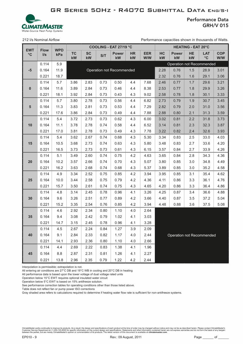
Performance DataGRH/V 015
212 l/s Nominal Airflow Performance capacities shown in thousands of Watts.
EWT °C
Flowl/s
WPDkPa
COOLING - EAT 27/19 °C HEATING - EAT 20°C
TC kW
SC kW
S/TPower
kWHR kW
EER W/W
HC kW
Power kW
HE kW
LAT °C
COP W/W
-5
0.114 5.9Operation not Recommended
Operation not Recommended0.164 11.9 2.28 0.76 1.5 28.9 3.010.221 18.7 2.32 0.76 1.6 29.1 3.06
0
0.114 5.7 3.86 2.83 0.73 0.50 4.4 7.68 2.46 0.77 1.7 29.6 3.210.164 11.6 3.89 2.84 0.73 0.46 4.4 8.38 2.53 0.77 1.8 29.9 3.260.221 18.1 3.92 2.84 0.73 0.43 4.3 9.02 2.58 0.78 1.8 30.1 3.33
5
0.114 5.7 3.80 2.78 0.73 0.56 4.4 6.82 2.73 0.79 1.9 30.7 3.450.164 11.3 3.83 2.81 0.73 0.53 4.4 7.29 2.82 0.79 2.0 31.0 3.560.221 17.6 3.86 2.84 0.73 0.49 4.4 7.88 2.88 0.80 2.1 31.3 3.59
10
0.114 5.4 3.72 2.73 0.73 0.62 4.3 6.00 3.02 0.81 2.2 31.8 3.730.164 11.1 3.78 2.78 0.74 0.58 4.4 6.52 3.14 0.81 2.3 32.3 3.870.221 17.0 3.81 2.78 0.73 0.49 4.3 7.78 3.22 0.82 2.4 32.6 3.93
15
0.114 5.4 3.62 2.67 0.74 0.68 4.3 5.30 3.34 0.83 2.5 33.0 4.030.164 10.5 3.68 2.73 0.74 0.63 4.3 5.80 3.48 0.83 2.7 33.6 4.200.221 16.5 3.73 2.73 0.73 0.61 4.3 6.15 3.57 0.84 2.7 33.9 4.26
20
0.114 5.1 3.49 2.60 0.74 0.75 4.2 4.63 3.65 0.84 2.8 34.3 4.360.164 10.2 3.57 2.66 0.74 0.70 4.3 5.07 3.80 0.85 3.0 34.8 4.490.221 16.2 3.63 2.68 0.74 0.68 4.3 5.37 3.89 0.85 3.0 35.2 4.58
25
0.114 4.9 3.34 2.52 0.75 0.85 4.2 3.94 3.95 0.85 3.1 35.4 4.620.164 10.0 3.44 2.58 0.75 0.79 4.2 4.36 4.11 0.86 3.3 36.1 4.760.221 15.7 3.50 2.61 0.74 0.75 4.3 4.65 4.20 0.86 3.3 36.4 4.86
30
0.114 4.8 3.14 2.45 0.78 0.96 4.1 3.26 4.25 0.87 3.4 36.6 4.880.164 9.6 3.26 2.51 0.77 0.89 4.2 3.66 4.40 0.87 3.5 37.2 5.040.221 15.2 3.35 2.54 0.76 0.85 4.2 3.94 4.48 0.88 3.6 37.5 5.08
35
0.114 4.6 2.92 2.34 0.80 1.10 4.0 2.64
Operation not Recommended
0.164 9.4 3.08 2.42 0.79 1.02 4.1 3.030.221 14.7 3.15 2.45 0.78 0.96 4.1 3.28
40
0.114 4.5 2.67 2.24 0.84 1.27 3.9 2.090.164 9.1 2.84 2.33 0.82 1.17 4.0 2.440.221 14.1 2.93 2.36 0.80 1.10 4.0 2.66
45
0.114 4.4 2.69 2.22 0.83 1.38 4.1 1.96
0.164 8.8 2.87 2.31 0.81 1.26 4.1 2.27
0.221 13.8 2.96 2.35 0.79 1.22 4.2 2.44
Interpolation is permissible; extrapolation is not. All entering air conditions are 27°C DB and 19°C WB in cooling and 20°C DB in heating All performance data is based upon the lower voltage of dual voltage rated units Operation below 15°C EWT requires optional insulated water circuit Operation below 5°C EWT is based on 15% antifreeze solution. See performance correction tables for operating conditions other than those listed above. Table does not reflect fan or pump power ISO correctionsGray shaded area refers to calculations required to determine if heating water flow rate is sufficient for non-antifreeze systems.

ClimateMaster works continually to improve its products. As a result, the design and specifications of each product at the time of order may be changed without notice and may not be as described herein. Please contact ClimateMaster's Customer Service Department at +1-405-745-6000 for specific information on the current design and specifications. Statements and other information contained herein are not express warranties and do not form the basis of any bargain between the parties, but are merely ClimateMaster's opinion or commendation of its products. The latest version of this document is available at climatemaster.com.
Page ______ of ______Rev.: 09 August, 2011EP010 - 10
GR Series 50Hz - R407C Submittal Data Eng/S-I
Performance DataGRH/V 019
212 l/s Nominal Airflow Performance capacities shown in thousands of Watts.
EWT °C
Flowl/s
WPDkPa
COOLING - EAT 27/19 °C HEATING - EAT 20°C
TC kW
SC kW
S/TPower
kWHR kW
EER W/W
HC kW
Power kW
HE kW
LAT °C
COP W/W
-5
0.145 11.9
Operation not Recommended
Operation not Recommended0.215 23.4 3.35 1.17 2.2 33.1 2.86
0.284 38.2 3.37 1.17 2.2 33.2 2.87
0
0.145 11.6 6.53 4.43 0.68 1.09 7.6 5.99 3.59 1.20 2.4 34.0 2.980.215 22.8 6.79 4.56 0.67 1.01 7.8 6.71 3.69 1.22 2.5 34.4 3.030.284 37.1 6.93 4.65 0.67 0.97 7.9 7.13 3.76 1.23 2.5 34.7 3.06
5
0.145 11.3 6.24 4.29 0.69 1.18 7.4 5.29 4.05 1.27 2.8 35.8 3.190.215 22.1 6.47 4.38 0.68 1.11 7.6 5.84 4.20 1.29 2.9 36.4 3.260.284 36.1 6.62 4.47 0.67 1.07 7.7 6.18 4.32 1.31 3.0 36.9 3.30
10
0.145 11.1 5.92 4.16 0.70 1.26 7.2 4.70 4.60 1.35 3.3 38.0 3.410.215 21.5 6.15 4.25 0.69 1.19 7.3 5.17 4.84 1.38 3.5 38.9 3.500.284 35.3 6.30 4.31 0.68 1.16 7.5 5.43 4.95 1.40 3.6 39.4 3.54
15
0.145 10.5 5.63 4.06 0.72 1.34 7.0 4.20 5.23 1.44 3.8 40.5 3.640.215 21.0 5.86 4.14 0.71 1.28 7.1 4.58 5.50 1.48 4.0 41.5 3.720.284 34.2 5.98 4.18 0.70 1.24 7.2 4.82 5.64 1.50 4.1 42.1 3.76
20
0.145 10.2 5.29 3.95 0.75 1.42 6.7 3.72 5.87 1.53 4.3 42.9 3.830.215 20.5 5.53 4.04 0.73 1.36 6.9 4.06 6.15 1.57 4.6 44.1 3.920.284 33.1 5.67 4.07 0.72 1.33 7.0 4.26 6.30 1.59 4.7 44.6 3.96
25
0.145 10.0 4.95 3.85 0.78 1.50 6.5 3.29 6.46 1.61 4.8 45.3 4.010.215 19.7 5.18 3.93 0.76 1.44 6.6 3.59 6.73 1.65 5.1 46.3 4.090.284 32.1 5.33 3.96 0.74 1.41 6.7 3.77 6.88 1.66 5.2 46.9 4.15
30
0.145 9.6 4.56 3.73 0.82 1.58 6.1 2.89 7.20 1.75 5.4 48.1 4.110.215 19.1 4.82 3.82 0.79 1.53 6.4 3.16 7.48 1.74 5.7 49.2 4.300.284 31.0 4.96 3.86 0.78 1.50 6.5 3.31 7.63 1.75 5.9 49.8 4.36
35
0.145 9.4 4.15 3.55 0.86 1.67 5.8 2.48
Operation not Recommended
0.215 18.5 4.43 3.66 0.83 1.61 6.0 2.750.284 30.2 4.56 3.72 0.82 1.58 6.1 2.88
40
0.145 9.2 3.69 3.31 0.90 1.76 5.5 2.090.215 17.9 3.98 3.47 0.87 1.70 5.7 2.340.284 29.1 4.13 3.53 0.86 1.67 5.8 2.47
45
0.145 8.8 3.63 3.31 0.91 1.89 5.5 1.920.215 17.4 3.90 3.43 0.88 1.84 5.7 2.110.284 28.4 4.04 3.47 0.86 1.82 5.9 2.22
Interpolation is permissible; extrapolation is not. All entering air conditions are 27°C DB and 19°C WB in cooling and 20°C DB in heating All performance data is based upon the lower voltage of dual voltage rated units Operation below 15°C EWT requires optional insulated water circuit Operation below 5°C EWT is based on 15% antifreeze solution. See performance correction tables for operating conditions other than those listed above. Table does not reflect fan or pump power ISO correctionsGray shaded area refers to calculations required to determine if heating water flow rate is sufficient for non-antifreeze systems.

ClimateMaster works continually to improve its products. As a result, the design and specifications of each product at the time of order may be changed without notice and may not be as described herein. Please contact ClimateMaster's Customer Service Department at +1-405-745-6000 for specific information on the current design and specifications. Statements and other information contained herein are not express warranties and do not form the basis of any bargain between the parties, but are merely ClimateMaster's opinion or commendation of its products. The latest version of this document is available at climatemaster.com.
Page ______ of ______Rev.: 09 August, 2011EP010 - 11
GR Series 50Hz - R407C Submittal Data Eng/S-I
Performance DataGRH/V 024
307 l/s Nominal Airflow Performance capacities shown in thousands of Watts.
EWT °C
Flowl/s
WPDkPa
COOLING - EAT 27/19 °C HEATING - EAT 20°C
TC kW
SC kW
S/TPower
kWHR kW
EER W/W
HC kW
Power kW
HE kW
LAT °C
COP W/W
-5
0.189 19.0Operation not Recommended
Operation not Recommended0.284 38.2 3.82 1.27 2.6 30.3 3.020.379 63.1 3.89 1.28 2.6 30.5 3.05
0
0.189 18.4 7.51 5.28 0.70 1.19 8.7 6.30 4.33 1.37 3.0 31.7 3.170.284 37.1 7.84 5.30 0.68 1.12 9.0 6.99 4.49 1.40 3.1 32.1 3.220.379 61.2 8.01 5.26 0.66 1.08 9.1 7.41 4.58 1.42 3.2 32.4 3.23
5
0.189 17.9 7.14 5.17 0.72 1.29 8.4 5.54 4.96 1.48 3.5 33.4 3.350.284 36.1 7.40 5.26 0.71 1.22 8.6 6.06 5.17 1.51 3.7 34.0 3.420.379 59.6 7.55 5.29 0.70 1.18 8.7 6.39 5.26 1.53 3.7 34.2 3.44
10
0.189 17.3 6.80 5.04 0.74 1.38 8.2 4.93 5.60 1.58 4.0 35.1 3.540.284 35.3 7.03 5.13 0.73 1.32 8.4 5.33 5.80 1.61 4.2 35.7 3.600.379 58.0 7.15 5.19 0.73 1.28 8.4 5.59 5.92 1.63 4.3 36.0 3.63
15
0.189 16.8 6.46 4.86 0.75 1.48 7.9 4.37 6.20 1.67 4.5 36.8 3.720.284 34.2 6.69 4.97 0.74 1.41 8.1 4.75 6.46 1.70 4.8 37.5 3.800.379 56.4 6.81 5.03 0.74 1.38 8.2 4.94 6.58 1.72 4.9 37.8 3.83
20
0.189 16.3 6.11 4.65 0.76 1.58 7.7 3.87 6.81 1.75 5.1 38.4 3.890.284 33.1 6.35 4.79 0.75 1.51 7.9 4.21 7.08 1.78 5.3 39.1 3.970.379 54.8 6.47 4.85 0.75 1.48 7.9 4.37 7.19 1.80 5.4 39.4 3.99
25
0.189 15.7 5.75 4.48 0.78 1.68 7.4 3.43 7.38 1.83 5.6 39.9 4.040.284 32.1 5.98 4.60 0.77 1.61 7.6 3.71 7.64 1.86 5.8 40.6 4.120.379 53.0 6.10 4.66 0.76 1.58 7.7 3.87 7.78 1.88 5.9 41.0 4.15
30
0.189 15.5 5.35 4.32 0.81 1.78 7.1 3.00 8.06 1.96 6.1 41.8 4.110.284 31.0 5.61 4.41 0.79 1.71 7.3 3.28 8.33 1.94 6.4 42.5 4.290.379 51.2 5.73 4.47 0.78 1.68 7.4 3.41 8.47 1.96 6.5 42.9 4.32
35
0.189 15.0 4.89 4.16 0.85 1.89 6.8 2.59
Operation not Recommended
0.284 30.2 5.17 4.25 0.82 1.82 7.0 2.840.379 49.6 5.30 4.31 0.81 1.79 7.1 2.96
40
0.189 14.4 4.37 3.98 0.91 2.00 6.4 2.190.284 29.1 4.68 4.08 0.87 1.93 6.6 2.420.379 48.0 4.81 4.14 0.86 1.90 6.7 2.53
45
0.189 14.0 4.31 3.87 0.90 2.15 6.5 2.000.284 28.4 4.57 3.99 0.87 2.09 6.7 2.190.379 46.8 4.69 4.06 0.87 2.07 6.8 2.27
Interpolation is permissible; extrapolation is not. All entering air conditions are 27°C DB and 19°C WB in cooling and 20°C DB in heating All performance data is based upon the lower voltage of dual voltage rated units Operation below 15°C EWT requires optional insulated water circuit Operation below 5°C EWT is based on 15% antifreeze solution. See performance correction tables for operating conditions other than those listed above. Table does not reflect fan or pump power ISO correctionsGray shaded area refers to calculations required to determine if heating water flow rate is sufficient for non-antifreeze systems.

ClimateMaster works continually to improve its products. As a result, the design and specifications of each product at the time of order may be changed without notice and may not be as described herein. Please contact ClimateMaster's Customer Service Department at +1-405-745-6000 for specific information on the current design and specifications. Statements and other information contained herein are not express warranties and do not form the basis of any bargain between the parties, but are merely ClimateMaster's opinion or commendation of its products. The latest version of this document is available at climatemaster.com.
Page ______ of ______Rev.: 09 August, 2011EP010 - 12
GR Series 50Hz - R407C Submittal Data Eng/S-I
Performance DataGRH/V 030
349 l/s Nominal Airflow Performance capacities shown in thousands of Watts.
EWT °C
Flowl/s
WPDkPa
COOLING - EAT 27/19 °C HEATING - EAT 20°C
TC kW
SC kW
S/TPower
kWHR kW
EER W/W
HC kW
Power kW
HE kW
LAT °C
COP W/W
-5
0.240 9.2Operation not Recommended
Operation not Recommended0.347 17.8 4.83 1.56 3.3 31.5 3.100.473 30.5 4.87 1.57 3.3 31.6 3.10
0
0.240 8.9 7.87 5.30 0.67 1.35 9.2 5.81 5.11 1.65 3.5 32.1 3.090.347 17.2 7.98 5.30 0.66 1.30 9.3 6.13 5.23 1.67 3.6 32.4 3.120.473 29.7 8.05 5.30 0.66 1.27 9.3 6.34 5.29 1.68 3.6 32.6 3.14
5
0.240 8.6 7.65 5.30 0.69 1.46 9.1 5.23 5.67 1.75 3.9 33.5 3.240.347 16.7 7.77 5.30 0.68 1.40 9.2 5.54 5.82 1.78 4.0 33.8 3.270.473 28.9 7.86 5.30 0.68 1.36 9.2 5.77 5.92 1.79 4.1 34.1 3.31
10
0.240 8.4 7.42 5.28 0.71 1.58 9.0 4.69 6.33 1.84 4.5 35.0 3.440.347 16.1 7.56 5.30 0.70 1.51 9.1 5.01 6.54 1.87 4.7 35.5 3.500.473 28.1 7.62 5.30 0.70 1.47 9.1 5.18 6.68 1.88 4.8 35.9 3.55
15
0.240 8.1 7.12 5.22 0.73 1.71 8.8 4.18 7.07 1.92 5.1 36.8 3.680.347 15.9 7.30 5.25 0.72 1.64 8.9 4.46 7.30 1.95 5.3 37.3 3.740.473 27.3 7.38 5.28 0.71 1.60 9.0 4.63 7.45 1.96 5.5 37.7 3.80
20
0.240 8.1 6.81 5.12 0.75 1.84 8.7 3.70 7.78 1.99 5.8 38.5 3.900.347 15.4 6.99 5.18 0.74 1.77 8.8 3.95 8.02 2.02 6.0 39.1 3.980.473 26.5 7.08 5.21 0.74 1.72 8.8 4.11 8.19 2.03 6.2 39.4 4.03
25
0.240 7.9 6.43 5.00 0.78 1.97 8.4 3.26 8.43 2.06 6.4 40.0 4.010.347 14.8 6.63 5.08 0.77 1.91 8.5 3.48 8.65 2.08 6.6 40.5 4.160.473 25.7 6.74 5.11 0.76 1.86 8.6 3.62 8.78 2.09 6.7 40.9 4.20
30
0.240 7.5 6.02 4.84 0.80 2.11 8.1 2.85 9.24 2.16 7.1 41.9 4.270.347 14.3 6.25 4.94 0.79 2.04 8.3 3.06 9.44 2.15 7.3 42.4 4.400.473 25.0 6.37 4.99 0.78 2.00 8.4 3.19 9.58 2.16 7.4 42.8 4.43
35
0.240 7.3 5.57 4.62 0.83 2.24 7.8 2.48
Operation not Recommended
0.347 13.9 5.80 4.73 0.82 2.18 8.0 2.660.473 24.1 5.93 4.81 0.81 2.14 8.1 2.77
40
0.240 7.1 5.07 4.36 0.86 2.38 7.5 2.130.347 13.5 5.30 4.48 0.85 2.32 7.6 2.290.473 23.3 5.45 4.57 0.84 2.28 7.7 2.39
45
0.240 6.9 5.04 4.44 0.88 2.60 7.6 1.940.347 13.1 5.29 4.58 0.87 2.53 7.8 2.090.473 22.7 5.43 4.67 0.86 2.48 7.9 2.19
Interpolation is permissible; extrapolation is not. All entering air conditions are 27°C DB and 19°C WB in cooling and 20°C DB in heating All performance data is based upon the lower voltage of dual voltage rated units Operation below 15°C EWT requires optional insulated water circuit Operation below 5°C EWT is based on 15% antifreeze solution. See performance correction tables for operating conditions other than those listed above. Table does not reflect fan or pump power ISO correctionsGray shaded area refers to calculations required to determine if heating water flow rate is sufficient for non-antifreeze systems.

ClimateMaster works continually to improve its products. As a result, the design and specifications of each product at the time of order may be changed without notice and may not be as described herein. Please contact ClimateMaster's Customer Service Department at +1-405-745-6000 for specific information on the current design and specifications. Statements and other information contained herein are not express warranties and do not form the basis of any bargain between the parties, but are merely ClimateMaster's opinion or commendation of its products. The latest version of this document is available at climatemaster.com.
Page ______ of ______Rev.: 09 August, 2011EP010 - 13
GR Series 50Hz - R407C Submittal Data Eng/S-I
Performance DataGRH/V 036
437 l/s Nominal Airflow Performance capacities shown in thousands of Watts.
EWT °C
Flowl/s
WPDkPa
COOLING - EAT 27/19 °C HEATING - EAT 20°C
TC kW
SC kW
S/TPower
kWHR kW
EER W/W
HC kW
Power kW
HE kW
LAT °C
COP W/W
-5
0.284 6.5Operation not Recommended
Operation not Recommended0.429 15.1 5.99 2.07 3.9 31.4 2.890.568 26.3 6.11 2.08 4.0 31.6 2.94
0
0.284 6.3 9.89 6.85 0.69 1.81 11.7 5.47 6.67 2.15 4.5 32.6 3.110.429 14.6 10.10 6.95 0.69 1.73 11.8 5.82 6.92 2.18 4.7 33.1 3.180.568 25.6 10.22 7.00 0.69 1.70 11.9 6.02 7.04 2.19 4.8 33.3 3.21
5
0.284 6.2 9.58 6.70 0.70 1.93 11.5 4.95 7.55 2.27 5.3 34.3 3.330.429 14.3 9.78 6.81 0.70 1.84 11.6 5.31 7.84 2.31 5.5 34.9 3.400.568 25.0 9.90 6.84 0.69 1.81 11.7 5.46 7.99 2.33 5.7 35.1 3.43
10
0.284 6.0 9.26 6.59 0.71 2.06 11.3 4.50 8.47 2.40 6.1 36.1 3.530.429 13.8 9.47 6.65 0.70 1.97 11.4 4.81 8.79 2.45 6.3 36.7 3.590.568 24.2 9.58 6.71 0.70 1.93 11.5 4.97 8.97 2.48 6.5 37.0 3.62
15
0.284 5.7 8.92 6.46 0.72 2.19 11.1 4.06 9.37 2.54 6.8 37.8 3.680.429 13.5 9.15 6.55 0.72 2.11 11.3 4.33 9.74 2.60 7.1 38.5 3.740.568 23.7 9.24 6.58 0.71 2.07 11.3 4.48 9.94 2.63 7.3 38.8 3.78
20
0.284 5.7 8.53 6.38 0.75 2.35 10.9 3.64 10.29 2.69 7.6 39.5 3.830.429 13.0 8.79 6.44 0.73 2.25 11.0 3.91 10.69 2.75 7.9 40.3 3.890.568 22.9 8.90 6.47 0.73 2.21 11.1 4.03 10.92 2.78 8.1 40.7 3.93
25
0.284 5.5 8.07 6.28 0.78 2.49 10.6 3.24 11.21 2.82 8.4 41.2 3.980.429 12.6 8.36 6.34 0.76 2.40 10.8 3.48 11.66 2.88 8.8 42.1 4.050.568 22.1 8.49 6.37 0.75 2.36 10.9 3.60 11.90 2.91 9.0 42.5 4.09
30
0.284 5.3 7.59 6.17 0.81 2.64 10.2 2.88 12.28 3.06 9.2 43.3 4.010.429 12.2 7.88 6.23 0.79 2.55 10.4 3.09 12.77 3.03 9.7 44.2 4.210.568 21.5 8.03 6.26 0.78 2.51 10.5 3.20 13.03 3.06 10.0 44.7 4.26
35
0.284 5.1 6.98 6.02 0.86 2.79 9.8 2.50
Operation not Recommended
0.429 11.8 7.31 6.11 0.84 2.71 10.0 2.700.568 20.8 7.47 6.14 0.82 2.67 10.1 2.80
40
0.284 5.0 6.30 5.80 0.92 2.95 9.2 2.140.429 11.4 6.66 5.94 0.89 2.86 9.5 2.330.568 20.1 6.85 5.98 0.87 2.82 9.7 2.43
45
0.284 4.8 6.30 5.78 0.92 3.16 9.5 1.990.429 11.1 6.65 5.87 0.88 3.07 9.7 2.160.568 19.6 6.82 5.90 0.86 3.03 9.9 2.25
Interpolation is permissible; extrapolation is not. All entering air conditions are 27°C DB and 19°C WB in cooling and 20°C DB in heating All performance data is based upon the lower voltage of dual voltage rated units Operation below 15°C EWT requires optional insulated water circuit Operation below 5°C EWT is based on 15% antifreeze solution. See performance correction tables for operating conditions other than those listed above. Table does not reflect fan or pump power ISO correctionsGray shaded area refers to calculations required to determine if heating water flow rate is sufficient for non-antifreeze systems.

ClimateMaster works continually to improve its products. As a result, the design and specifications of each product at the time of order may be changed without notice and may not be as described herein. Please contact ClimateMaster's Customer Service Department at +1-405-745-6000 for specific information on the current design and specifications. Statements and other information contained herein are not express warranties and do not form the basis of any bargain between the parties, but are merely ClimateMaster's opinion or commendation of its products. The latest version of this document is available at climatemaster.com.
Page ______ of ______Rev.: 09 August, 2011EP010 - 14
GR Series 50Hz - R407C Submittal Data Eng/S-I
Performance DataGRH/V 042
530 l/s Nominal Airflow Performance capacities shown in thousands of Watts.
EWT °C
Flowl/s
WPDkPa
COOLING - EAT 27/19 °C HEATING - EAT 20°C
TC kW
SC kW
S/TPower
kWHR kW
EER W/W
HC kW
Power kW
HE kW
LAT °C
COP W/W
-5
0.334 9.2Operation not Recommended
Operation not Recommended0.498 20.2 7.08 2.11 5.0 31.1 3.360.663 36.1 7.16 2.14 5.0 31.2 3.35
0
0.334 8.9 11.89 8.24 0.69 1.83 13.7 6.49 7.66 2.22 5.4 32.0 3.450.498 19.6 12.01 8.29 0.69 1.78 13.8 6.75 7.87 2.25 5.6 32.3 3.500.663 35.0 12.13 8.35 0.69 1.72 13.8 7.05 8.06 2.28 5.8 32.6 3.53
5
0.334 8.6 12.22 8.60 0.70 1.98 14.2 6.18 8.51 2.34 6.2 33.3 3.630.498 19.1 12.34 8.66 0.70 1.92 14.3 6.44 8.74 2.37 6.4 33.7 3.680.663 34.0 12.46 8.72 0.70 1.86 14.3 6.71 8.98 2.41 6.6 34.0 3.72
10
0.334 8.4 12.22 8.76 0.72 2.14 14.4 5.71 9.38 2.46 6.9 34.7 3.810.498 18.5 12.34 8.82 0.71 2.07 14.4 5.96 9.61 2.49 7.1 35.0 3.860.663 33.2 12.46 8.88 0.71 2.00 14.5 6.23 9.91 2.54 7.4 35.5 3.90
15
0.334 8.1 11.91 8.76 0.74 2.29 14.2 5.19 10.20 2.56 7.6 35.9 3.980.498 18.0 12.02 8.82 0.73 2.22 14.2 5.41 10.48 2.60 7.9 36.4 4.040.663 32.1 12.17 8.88 0.73 2.15 14.3 5.65 10.78 2.64 8.1 36.8 4.08
20
0.334 7.8 11.40 8.62 0.76 2.46 13.9 4.63 10.97 2.64 8.3 37.1 4.150.498 17.5 11.52 8.68 0.75 2.38 13.9 4.83 11.26 2.68 8.6 37.6 4.200.663 31.3 11.64 8.74 0.75 2.31 13.9 5.05 11.58 2.74 8.8 38.1 4.23
25
0.334 7.6 10.75 8.40 0.78 2.63 13.4 4.08 11.61 2.71 8.9 38.1 4.290.498 16.9 10.85 8.46 0.78 2.55 13.4 4.26 11.92 2.75 9.2 38.6 4.340.663 30.3 10.96 8.52 0.78 2.46 13.4 4.46 12.24 2.82 9.4 39.1 4.35
30
0.334 7.4 9.46 7.94 0.84 2.92 12.4 3.24 12.42 2.91 9.5 39.4 4.260.498 16.4 9.55 7.99 0.84 2.82 12.4 3.39 12.74 2.83 9.9 39.9 4.500.663 29.5 9.67 8.02 0.83 2.72 12.4 3.56 13.09 2.91 10.2 40.5 4.49
35
0.334 7.0 8.32 7.52 0.90 3.16 11.5 2.63
Operation not Recommended
0.498 16.0 8.40 7.56 0.90 3.06 11.5 2.750.663 28.4 8.51 7.61 0.89 2.95 11.5 2.89
40
0.334 6.9 7.63 7.27 0.95 3.34 11.0 2.290.498 15.6 7.69 7.32 0.95 3.22 10.9 2.390.663 27.4 7.81 7.35 0.94 3.01 10.9 2.52
45
0.334 6.6 7.82 7.47 0.96 3.63 11.4 2.160.498 15.1 7.89 7.52 0.95 3.50 11.4 2.260.663 26.8 8.00 7.55 0.94 3.37 11.4 2.38
Interpolation is permissible; extrapolation is not. All entering air conditions are 27°C DB and 19°C WB in cooling and 20°C DB in heating All performance data is based upon the lower voltage of dual voltage rated units Operation below 15°C EWT requires optional insulated water circuit Operation below 5°C EWT is based on 15% antifreeze solution. See performance correction tables for operating conditions other than those listed above.

ClimateMaster works continually to improve its products. As a result, the design and specifications of each product at the time of order may be changed without notice and may not be as described herein. Please contact ClimateMaster's Customer Service Department at +1-405-745-6000 for specific information on the current design and specifications. Statements and other information contained herein are not express warranties and do not form the basis of any bargain between the parties, but are merely ClimateMaster's opinion or commendation of its products. The latest version of this document is available at climatemaster.com.
Page ______ of ______Rev.: 09 August, 2011EP010 - 15
GR Series 50Hz - R407C Submittal Data Eng/S-I
Performance DataGRH/V 048
630 l/s Nominal Airflow Performance capacities shown in thousands of Watts.
EWT °C
Flowl/s
WPDkPa
COOLING - EAT 27/19 °C HEATING - EAT 20°C
TC kW
SC kW
S/TPower
kWHR kW
EER W/W
HC kW
Power kW
HE kW
LAT °C
COP W/W
-5
0.379 17.6Operation not Recommended
Operation not Recommended0.568 33.2 7.15 2.28 4.9 29.4 3.140.757 52.2 7.29 2.31 5.0 29.6 3.16
0
0.379 17.2 13.75 9.68 0.70 2.09 15.8 6.57 8.17 2.50 5.7 30.7 3.260.568 32.4 13.87 9.74 0.70 1.92 15.8 7.23 8.51 2.57 5.9 31.2 3.300.757 50.8 13.92 9.75 0.70 1.83 15.7 7.60 8.69 2.61 6.1 31.4 3.34
5
0.379 16.7 13.47 9.60 0.71 2.32 15.8 5.80 9.57 2.78 6.8 32.6 3.440.568 31.6 13.65 9.66 0.71 2.17 15.8 6.28 9.99 2.86 7.1 33.1 3.490.757 49.5 13.74 9.69 0.71 2.01 15.8 6.56 10.23 2.90 7.3 33.4 3.52
10
0.379 16.1 13.10 9.50 0.72 2.52 15.6 5.20 10.99 3.04 8.0 34.5 3.620.568 30.5 13.36 9.55 0.71 2.39 15.8 5.59 11.52 3.13 8.4 35.1 3.680.757 48.1 13.45 9.61 0.71 2.32 15.8 5.80 11.78 3.18 8.6 35.5 3.71
15
0.379 15.6 12.65 9.36 0.74 2.72 15.4 4.66 12.44 3.28 9.2 36.4 3.790.568 29.7 12.94 9.45 0.73 2.59 15.5 5.00 13.00 3.38 9.6 37.1 3.840.757 46.8 13.08 9.48 0.72 2.53 15.6 5.18 13.31 3.42 9.9 37.5 3.89
20
0.379 15.3 12.11 9.21 0.76 2.92 15.0 4.15 13.80 3.51 10.3 38.1 3.930.568 28.9 12.45 9.32 0.75 2.79 15.2 4.47 14.38 3.60 10.8 38.9 3.990.757 45.4 12.62 9.35 0.74 2.72 15.3 4.64 14.68 3.65 11.0 39.3 4.02
25
0.379 14.8 11.49 9.03 0.79 3.14 14.6 3.66 15.04 3.71 11.3 39.8 4.060.568 28.1 11.89 9.15 0.77 3.00 14.9 3.97 15.59 3.79 11.8 40.5 4.110.757 44.1 12.06 9.20 0.76 2.93 15.0 4.12 15.84 3.83 12.0 40.8 4.13
30
0.379 14.3 10.79 8.82 0.82 3.40 14.2 3.17 16.59 4.07 12.5 41.8 4.080.568 27.1 11.23 8.94 0.80 3.24 14.5 3.47 17.13 4.02 13.1 42.5 4.260.757 42.6 11.44 9.03 0.79 3.16 14.6 3.62 17.34 4.07 13.3 42.8 4.26
35
0.379 13.8 10.01 8.54 0.85 3.73 13.7 2.68
Operation not Recommended
0.568 26.2 10.48 8.70 0.83 3.54 14.0 2.960.757 41.1 10.71 8.79 0.82 3.45 14.2 3.11
40
0.379 13.3 9.14 8.21 0.90 4.11 13.3 2.220.568 25.4 9.65 8.41 0.87 3.89 13.5 2.480.757 39.8 9.90 8.51 0.86 3.78 13.7 2.62
45
0.379 13.0 9.14 8.23 0.90 4.40 13.5 2.080.568 24.7 9.67 8.42 0.87 4.21 13.9 2.290.757 38.8 9.94 8.52 0.86 4.13 14.1 2.40
Interpolation is permissible; extrapolation is not. All entering air conditions are 27°C DB and 19°C WB in cooling and 20°C DB in heating All performance data is based upon the lower voltage of dual voltage rated units Operation below 15°C EWT requires optional insulated water circuit Operation below 5°C EWT is based on 15% antifreeze solution. See performance correction tables for operating conditions other than those listed above. Table does not reflect fan or pump power ISO correctionsGray shaded area refers to calculations required to determine if heating water flow rate is sufficient for non-antifreeze systems.

ClimateMaster works continually to improve its products. As a result, the design and specifications of each product at the time of order may be changed without notice and may not be as described herein. Please contact ClimateMaster's Customer Service Department at +1-405-745-6000 for specific information on the current design and specifications. Statements and other information contained herein are not express warranties and do not form the basis of any bargain between the parties, but are merely ClimateMaster's opinion or commendation of its products. The latest version of this document is available at climatemaster.com.
Page ______ of ______Rev.: 09 August, 2011EP010 - 16
GR Series 50Hz - R407C Submittal Data Eng/S-I
Performance DataGRH/V 060
790 l/s Nominal Airflow Performance capacities shown in thousands of Watts.
EWT °C
Flowl/s
WPDkPa
COOLING - EAT 27/19 °C HEATING - EAT 20°C
TC kW
SC kW
S/TPower
kWHR kW
EER W/W
HC kW
Power kW
HE kW
LAT °C
COP W/W
-5
0.473 24.9Operation not Recommended
Operation not Recommended0.713 47.5 10.50 3.23 7.3 31.0 3.260.946 74.1 10.58 3.25 7.3 31.1 3.26
0
0.473 24.3 16.73 11.37 0.68 2.57 19.3 6.51 11.08 3.37 7.7 31.6 3.290.713 46.3 16.82 11.44 0.68 2.46 19.3 6.83 11.34 3.42 7.9 31.9 3.320.946 72.2 16.83 11.44 0.68 2.42 19.3 6.95 11.47 3.44 8.0 32.0 3.34
5
0.473 23.6 16.42 11.20 0.68 2.75 19.2 5.96 12.16 3.54 8.6 32.8 3.440.713 45.0 16.64 11.32 0.68 2.62 19.3 6.34 12.53 3.58 9.0 33.1 3.50
0.946 70.4 16.73 11.35 0.68 2.57 19.3 6.51 12.74 3.60 9.1 33.4 3.54
10
0.473 23.0 15.94 10.99 0.69 2.98 18.9 5.35 13.48 3.68 9.8 34.1 3.660.713 43.7 16.27 11.14 0.68 2.83 19.1 5.75 13.95 3.72 10.2 34.6 3.750.946 68.5 16.41 11.20 0.68 2.76 19.2 5.95 14.21 3.74 10.5 34.9 3.80
15
0.473 22.2 15.31 10.73 0.70 3.25 18.6 4.71 14.91 3.80 11.1 35.6 3.930.713 42.6 15.71 10.90 0.69 3.08 18.8 5.01 15.45 3.85 11.6 36.2 4.020.946 66.3 15.91 10.96 0.69 2.99 18.9 5.31 15.74 3.87 11.9 36.5 4.07
20
0.473 21.6 14.61 10.46 0.72 3.56 18.2 4.10 16.31 3.91 12.4 37.1 4.170.713 41.3 15.06 10.64 0.71 3.37 18.4 4.48 16.89 3.96 12.9 37.7 4.270.946 64.4 15.27 10.70 0.70 3.28 18.5 4.66 17.18 3.98 13.2 38.0 4.32
25
0.473 20.9 13.85 10.20 0.74 3.91 17.8 3.54 17.58 4.00 13.6 38.4 4.400.713 39.9 14.32 10.35 0.72 3.70 18.0 3.88 18.13 4.04 14.1 39.0 4.480.946 62.5 14.55 10.43 0.72 3.59 18.1 4.05 18.36 4.06 14.3 39.2 4.52
30
0.473 20.3 13.07 9.94 0.76 4.30 17.4 3.04 19.14 4.17 15.0 40.1 4.590.713 38.8 13.54 10.09 0.75 4.05 17.6 3.34 19.69 4.15 15.5 40.6 4.750.946 60.5 13.77 10.17 0.74 3.94 17.7 3.49 19.89 4.17 15.7 40.9 4.77
35
0.473 19.7 12.25 9.75 0.80 4.73 17.0 2.59
Operation not Recommended
0.713 37.5 12.73 9.86 0.77 4.47 17.2 2.850.946 58.5 12.97 9.92 0.76 4.35 17.3 2.98
40
0.473 19.1 11.48 9.58 0.83 5.20 16.7 2.210.713 36.2 11.93 9.66 0.81 4.92 16.9 2.420.946 56.6 12.15 9.72 0.80 4.79 16.9 2.54
45
0.473 18.5 11.24 9.34 0.83 5.62 16.9 2.000.713 35.3 11.79 9.47 0.80 5.29 17.1 2.230.946 55.1 12.06 9.55 0.79 5.13 17.2 2.35
Interpolation is permissible; extrapolation is not. All entering air conditions are 27°C DB and 19°C WB in cooling and 20°C DB in heating All performance data is based upon the lower voltage of dual voltage rated units Operation below 15°C EWT requires optional insulated water circuit Operation below 5°C EWT is based on 15% antifreeze solution. See performance correction tables for operating conditions other than those listed above. Table does not reflect fan or pump power ISO correctionsGray shaded area refers to calculations required to determine if heating water flow rate is sufficient for non-antifreeze systems.

ClimateMaster works continually to improve its products. As a result, the design and specifications of each product at the time of order may be changed without notice and may not be as described herein. Please contact ClimateMaster's Customer Service Department at +1-405-745-6000 for specific information on the current design and specifications. Statements and other information contained herein are not express warranties and do not form the basis of any bargain between the parties, but are merely ClimateMaster's opinion or commendation of its products. The latest version of this document is available at climatemaster.com.
Page ______ of ______Rev.: 09 August, 2011EP010 - 17
GR Series 50Hz - R407C Submittal Data Eng/S-I
Air Flow Correction Table
Entering Air Correction Table
Performance DataCorrection Tables
Airflow Cooling Heating
% ofRated
TotalCapacity
SensibleCapacity
PowerHeat of
RejectionHeatingCapacity
PowerHeat of
Extraction
75% 0.954 0.863 0.961 0.954 0.971 1.045 0.956
81% 0.966 0.897 0.971 0.967 0.979 1.029 0.969
88% 0.980 0.937 0.982 0.980 0.988 1.015 0.982
94% 0.992 0.968 0.990 0.992 0.994 1.007 0.992
100% 1.000 1.000 1.000 1.000 1.000 1.000 1.000
106% 1.007 1.031 1.009 1.007 1.005 0.995 1.007
113% 1.015 1.065 1.019 1.016 1.011 0.992 1.012
Cooling
EnteringAir WB
°C
TotalCapacity
Sensible Cooling Capacity Multiplier - Entering DB °C Power
Heat ofRejection
21 23 25 27 29.5 32 35
15 0.910 0.864 1.007 1.132 1.200 * * * 0.984 0.923
17 0.956 0.718 0.858 1.002 1.142 1.264 * * 0.992 0.963
19 1.000 0.575 0.715 0.856 1.000 1.176 * * 1.000 1.000
21 1.073 0.570 0.710 0.851 1.031 1.208 1.391 1.011 1.063
23 1.128 0.563 0.704 0.878 1.059 1.274 1.019 1.110
25 1.192 0.554 0.730 0.907 1.127 1.026 1.164
* = Sensible capacity equals total capacityAHRI/ISO/ASHRAE 13256-1 uses entering air conditions of Cooling - 27.0°C DB/19.0°C WB, 1and Heating - 20.0°C DB/15.0°C WB entering air temperature
Heating
EnteringAir DB °C
HeatingCapacity
PowerHeat of
Extraction
15 1.002 0.989 1.008
17 1.001 0.993 1.005
20 1.000 1.000 1.000
22 0.999 1.012 0.997
24 0.997 1.014 0.988
26 0.995 1.018 0.988

ClimateMaster works continually to improve its products. As a result, the design and specifications of each product at the time of order may be changed without notice and may not be as described herein. Please contact ClimateMaster's Customer Service Department at +1-405-745-6000 for specific information on the current design and specifications. Statements and other information contained herein are not express warranties and do not form the basis of any bargain between the parties, but are merely ClimateMaster's opinion or commendation of its products. The latest version of this document is available at climatemaster.com.
Page ______ of ______Rev.: 09 August, 2011EP010 - 18
GR Series 50Hz - R407C Submittal Data Eng/S-I
Antifreeze TypeAntifreeze
%
Cooling Heating WPDCorr. Fct.EWT -1°C
EWT 32°C EWT -1°C
Total Cap Sens Cap Power Htg Cap Power
Water 0 1.000 1.000 1.000 1.000 1.000 1.000
Propylene Glycol
5 0.995 0.995 1.003 0.989 0.997 1.070
15 0.986 0.986 1.009 0.968 0.990 1.210
25 0.978 0.978 1.014 0.947 0.983 1.360
Methanol
5 0.997 0.997 1.002 0.989 0.997 1.070
15 0.990 0.990 1.007 0.968 0.990 1.160
25 0.982 0.982 1.012 0.949 0.984 1.220
Ethanol
5 0.998 0.998 1.002 0.981 0.994 1.140
15 0.994 0.994 1.005 0.944 0.983 1.300
25 0.986 0.986 1.009 0.917 0.974 1.360
Ethylene Glycol
5 0.998 0.998 1.002 0.993 0.998 1.040
15 0.994 0.994 1.004 0.980 0.994 1.120
25 0.988 0.988 1.008 0.966 0.990 1.200
Antifreeze Correction Table

ClimateMaster works continually to improve its products. As a result, the design and specifications of each product at the time of order may be changed without notice and may not be as described herein. Please contact ClimateMaster's Customer Service Department at +1-405-745-6000 for specific information on the current design and specifications. Statements and other information contained herein are not express warranties and do not form the basis of any bargain between the parties, but are merely ClimateMaster's opinion or commendation of its products. The latest version of this document is available at climatemaster.com.
Page ______ of ______Rev.: 09 August, 2011EP010 - 19
GR Series 50Hz - R407C Submittal Data Eng/S-I
Blower Performance Data(PSC Motor) - Standard Unit
Airflow in l/s with wet coil and clean air filter.
ModelNominal
l/sMinimum
l/sFan
Speed
External Static Pressure (Pa)
0 25 50 75 100 125
GRH006 81 61
High 133 123 112 89 78
Medium 110 99 87 68
Low 98 90 75 60
GRH/V 009 113 85
High 165 151 142 118 99
Medium 160 146 127 113 94
Low 151 137 123 109 90
GRH/V 012 140 104
High 170 165 151 137 123 109
Medium 165 151 142 127 118
Low 146 137 127 118 104
GRH/V 015 212 160
High 345 316 288 250 198
Medium 321 302 274 241 189
Low 293 278 255 222 179
GRH/V 019 264 198
High 326 311 283 250 203
Medium 302 288 260 227 189
Low 293 269 245 217 179
GRH/V 024 307 231
High 396 368 335 302 260
Medium 387 359 326 297 255
Low 368 340 311 278 231
GRH/V 030 349 264
High 529 496 463 425 378 330
Medium 510 477 448 415 368 326
Low 458 439 406 378 340 297
GRH/V 036 437 326
High 614 576 519 463 415 373
Medium 580 543 488 434 392 349
Low 505 472 429 387 349
GRH/V 042 530 396
High 743 691 629 566 501 435
Medium 637 593 539 485 429
Low 498 463 421
GRH/V 048 630 472
High 793 738 672 604 535 464
Medium 777 723 658 592 524 455
Low 762 709 645 580 514 446
GRH/V 060 790 595
High 896 866 833 796 755 710
Medium 818 803 779 747 707 658
Low 748 731 709 683 653 618

ClimateMaster works continually to improve its products. As a result, the design and specifications of each product at the time of order may be changed without notice and may not be as described herein. Please contact ClimateMaster's Customer Service Department at +1-405-745-6000 for specific information on the current design and specifications. Statements and other information contained herein are not express warranties and do not form the basis of any bargain between the parties, but are merely ClimateMaster's opinion or commendation of its products. The latest version of this document is available at climatemaster.com.
Page ______ of ______Rev.: 09 August, 2011EP010 - 20
GR Series 50Hz - R407C Submittal Data Eng/S-I
Model 006 009 012 015 019 024 030 036 042 048 060
Compressor (1 each) Rotary Reciprocating Scroll
Factory Charge R407c, [kg] 0.34 0.37 0.37 0.70 0.88 0.91 1.19 1.36 1.19 1.59 2.41
PSC Fan Motor & Blower
Fan Motor Type/Speeds PSC/3 PSC/3 PSC/3 PSC/3 PSC/3 PSC/3 PSC/3 PSC/3 PSC/3 PSC/3 PSC/3
Fan Motor- [W] 30 75 75 124 150 250 373 560 560 560 746
Blower Wheel Size (Dia x W), [mm] 127 x 127 127 x 127 152 x 127 229 x 178 229 x 178 229 x 178 229 x 178 254 x 254 254 x 254 254 x 254 279 x 254
Water Connection Size
FPT - [mm] 1/2” 1/2” 1/2” 3/4” 3/4” 3/4” 3/4” 3/4” 1” 1” 1”
HWG Water Connection Size
FPT - [mm] 1/2” 1/2” 1/2” 1/2” 1/2” 1/2” 1/2” 1/2” 1/2” 1/2” 1/2”
Vertical
Air Coil Dimensions (H x W), [mm] N/A 254 x 406 254 x 406 406 x 406 406 x 406 406 x 406 508 x 508 508 x 508 711 x 508 711 x 508 711 x 635
Filter Standard - 25.4mm Throwaway, [mm] N/A 254 x 508 254 x 508 406 x 508 406 x 508 406 x 508 508 x 610 508 x 610 711 x 610 711 x 610 711 x 762
Weight - Operating, [kg] N/A 50.9 55.0 66.8 76.8 87.7 99.5 104.1 116.8 121.4 146.8
Weight - Packaged, [kg] N/A 55.5 59.5 71.4 81.4 92.3 105.0 109.5 122.3 126.8 153.6
Horizontal
Air Coil Dimensions (H x W), [mm] 254 x 406 254 x 406 254 x 406 406 x 406 406 x 406 406 x 406 457 x 559 457 x 559 457 x 787 457 x 787 508 x 889
Filter Standard - 25.4mm Throwaway, qty- [mm] 254 x 508 254 x 508 254 x 508 406 x 508 406 x 508 406 x 508 457 x 610 457 x 610 (2) 457 x 457 (2) 457 x 457 1 - 305 x 508
1 - 635 x 508
Weight - Operating, [kg] 50.0 50.9 55.0 66.8 76.8 87.7 99.5 104.1 116.8 121.4 146.8
Weight - Packaged, [kg] 54.5 55.5 59.5 71.4 81.4 92.3 105.0 109.5 122.3 126.8 153.6
Unit Maximum Water Working Pressure
Options Max Pressure [kPa]
Base Unit 2,068
Internal Motorized Water Valve (MWV) 2,068
Internal Auto Flow Valve 2,068
All units have dual vibration isolation compressor mounts for quiet operation, thermal expansion valves for refrigerant metering, and 22.2 mm and 28.6 mm electri-cal knockouts to accommodate field wiring.
FPT - Female Pipe Thread.
Condensate Drain Connection is 3/4” FPT.
Physical Data
Use the lowest maximum pressure rating when multiple options are combined.

ClimateMaster works continually to improve its products. As a result, the design and specifications of each product at the time of order may be changed without notice and may not be as described herein. Please contact ClimateMaster's Customer Service Department at +1-405-745-6000 for specific information on the current design and specifications. Statements and other information contained herein are not express warranties and do not form the basis of any bargain between the parties, but are merely ClimateMaster's opinion or commendation of its products. The latest version of this document is available at climatemaster.com.
Page ______ of ______Rev.: 09 August, 2011EP010 - 21
GR Series 50Hz - R407C Submittal Data Eng/S-I
GR - HorizontalDimensional Data
HorizontalModel
Overall Cabinet
AWidth
BLength
CHeight
006 - 012 cm 56.8 109.5 28.7
015 - 024 cm 56.8 109.5 43.9
030 cm 56.8 135.1 49.0
036 cm 56.8 135.1 49.0
042 - 048 cm 56.8 158.0 49.0
060 cm 64.5 180.8 54.1
HorizontalModel
Water Connections
1 2 3
LoopInD
LoopOutE
HSizeFPT
006 - 012 cm 6.1 13.7 1.5 1/2”
015 - 024 cm 6.1 12.4 1.5 3/4”
030 cm 6.1 13.7 1.5 3/4”
036 cm 6.1 13.7 1.5 3/4”
042 - 048 cm 6.1 13.7 1.5 1”
060 cm 6.1 13.7 1.5 1”
HorizontalModel
Electrical Knockouts
J22.2mm
K22.2mm
L28.6mm
LowVoltage
ExternalPump
PowerSupply
006 - 012 cm 8.9 14.0 20.8
015 - 024 cm 8.9 19.1 25.9
030 cm 14.5 24.6 31.0
036 cm 14.5 24.6 31.0
042 - 048 cm 14.5 24.6 31.0
060 cm 20.6 29.7 36.1
HorizontalModel
Discharge ConnectionDuct Flange Installed (+/- 2.5mm)
Return ConnectionUsing Return Air Opening
M NO
SupplyHeight
PSupplyWidth
Q RS
ReturnWidth
TReturnHeight
U V
006 - 012 cm 14.7 10.2 14.7 20.3 14.7 3.8 43.4 23.6 5.6 2.5
015 - 024 cm 12.7 14.2 26.4 23.6 12.7 3.8 43.4 38.9 5.6 2.5
030 cm 12.7 17.3 26.4 23.6 12.7 5.3 58.7 43.9 5.6 2.5
036 cm 7.4 9.7 34.3 33.3 7.4 4.8 58.7 43.9 5.6 2.5
042 - 048 cm 7.4 9.7 34.3 33.3 7.4 4.8 81.5 43.9 5.6 2.5
060 cm 14.7 12.7 34.5 33.8 14.7 7.4 91.7 49.0 5.6 2.5

ClimateMaster works continually to improve its products. As a result, the design and specifications of each product at the time of order may be changed without notice and may not be as described herein. Please contact ClimateMaster's Customer Service Department at +1-405-745-6000 for specific information on the current design and specifications. Statements and other information contained herein are not express warranties and do not form the basis of any bargain between the parties, but are merely ClimateMaster's opinion or commendation of its products. The latest version of this document is available at climatemaster.com.
Page ______ of ______Rev.: 09 August, 2011EP010 - 22
GR Series 50Hz - R407C Submittal Data Eng/S-I
Notes:1. While clear access to all removable panels is not required, installer should take care to comply with all building codes and allow adequate clearance for future field service. 2. Units are shipped with an air filter supported by a set of filter rails. These rails are not suitable for supporting duct work.
If a return duct is to be connected to the unit these rails should be removed and replaced with the ClimateMaster AFF Series accessory filter frame or some other air filter support system.3. Discharge flange and hanger brackets are factory installed.4. Condensate is 3/4” FPT copper.5. Blower service panel requires 61cm service access.6. Blower service access is through back panel on straight discharge units or through panel opposite air coil on back discharge units.
Legend:CAP = Control Access Panel BSP = Blower Service PanelCSP = Compressor Access Panel ASP = Alternative Service PanelFPT = Female Pipe Thread
GR - HorizontalDimensional Data
Right Return Straight DischargeFront
NP
BlowerOutlet
M
O
LegendCAP=Control Access PanelCSP=Compressor Service PanelBSP=Blower Service PanelASP=Alternate Service Panel
Right Return
Front
StraightDischarge3
CSP
BackDischarge
Condensate3 / 4” FPT
H
Front-View
KL
21
40.6mm
E
A
CAP
BSP
Right Return Right View -Air Coil Opening
Air Coil
C
VU
B
ASP T
S
Front
N
P
BlowerOutlet
M
O
Left Return Straight DischargeFront
BSP
LEFT RETURN RIGHT RETURN
Air Coil
CSP
Front
Left Return Left View -Air Coil Opening
27.9mm
C
V
T
SU
B
Unit Hanger Detail
X
Y
Fron
t
Z
Right Return Back Discharge
A
Air C
oil S
ide
C
RP
BlowerOutlet
Q
O
ASP CSP
BSP
61cm ServiceAccess
Front
Left Return
H
82.6mm
CSP
Condensate3 / 4” FPT
ASP
61cmServiceAccess
Air C
oil S
ide
O
A
C
Left Return Back Discharge
P
BlowerOutlet
Q
R
BSP
* Note: Shaded areas are recommended service areas, not required.
D
Optional 61cm Service Access
Optional 61cmService Access
82.6mm
MODEL cm cm cm006-024 109.5 61.9 51.8030-036 134.9 61.9 51.8042-048 157.7 61.9 51.8060 180.6 69.5 59.4
X Y Z
J
40.6mm
Power Supply28.6mm Knockout
22.2mmKnockout
Low Voltage22.2mmKnockout
3StraightDischarge
BackDischarge

ClimateMaster works continually to improve its products. As a result, the design and specifications of each product at the time of order may be changed without notice and may not be as described herein. Please contact ClimateMaster's Customer Service Department at +1-405-745-6000 for specific information on the current design and specifications. Statements and other information contained herein are not express warranties and do not form the basis of any bargain between the parties, but are merely ClimateMaster's opinion or commendation of its products. The latest version of this document is available at climatemaster.com.
Page ______ of ______Rev.: 09 August, 2011EP010 - 23
GR Series 50Hz - R407C Submittal Data Eng/S-I
GR - Vertical UpflowDimensional Data
VerticalUpflowModel
Overall Cabinet
AWidth
BDepth
CHeight
009 - 012 cm 56.8 54.9 54.7
015 - 024 cm 56.8 54.9 87.9
030 cm 56.8 65.1 103.1
036 cm 56.8 65.1 103.1
042 - 048 cm 56.8 65.1 123.4
060 cm 64.5 77.8 128.5
VerticalUpflowModel
Water Connections
1 2 3
LoopInD
LoopOutE
HSizeFPT
009 - 012 cm 6.6 13.7 19.8 1/2”
015 - 024 cm 6.1 12.2 21.6 3/4”
030 cm 6.1 13.7 24.6 3/4”
036 cm 6.1 13.7 24.6 3/4”
042 - 048 cm 6.1 13.7 24.6 1”
060 cm 6.1 13.7 27.2 1”
VerticalUpflowModel
Electrical Knockouts
J22.2mm
K22.2mm
L28.6mm
LowVoltage
ExternalPump
PowerSupply
009 - 012 cm 8.9 14.0 20.8
015 - 024 cm 8.9 19.1 25.9
030 cm 14.5 24.6 31.0
036 cm 14.5 24.6 31.0
042 - 048 cm 14.5 24.6 31.0
060 cm 20.6 29.7 36.1
VerticalUpflowModel
Discharge ConnectionDuct Flange Installed (+/- 2.5mm)
Return ConnectionUsing Return Air Opening
M NO
SupplyWidth
PSupplyDepth
Q RS
ReturnDepth
TReturnHeight
U
009 - 012 cm 26.9 17.3 14.7 20.3 15.2 5.6 43.4 23.6 2.5
015 - 024 cm 18.3 9.7 35.6 35.6 10.9 5.6 43.4 38.9 2.5
030 cm 18.3 14.7 35.6 35.6 10.9 5.6 53.6 48.8 2.5
036 cm 18.3 14.7 35.6 35.6 10.9 5.6 53.6 48.8 2.5
042 - 048 cm 18.3 14.7 35.6 35.6 10.9 5.6 53.6 69.1 2.5
060 cm 15.7 16.0 45.7 45.7 13.1 5.6 66.3 69.1 2.5

ClimateMaster works continually to improve its products. As a result, the design and specifications of each product at the time of order may be changed without notice and may not be as described herein. Please contact ClimateMaster's Customer Service Department at +1-405-745-6000 for specific information on the current design and specifications. Statements and other information contained herein are not express warranties and do not form the basis of any bargain between the parties, but are merely ClimateMaster's opinion or commendation of its products. The latest version of this document is available at climatemaster.com.
Page ______ of ______Rev.: 09 August, 2011EP010 - 24
GR Series 50Hz - R407C Submittal Data Eng/S-I
Notes:1. While clear access to all removable panels is not required, installer should take care to comply with all building codes and allow adequate clearance for future field service. 2. Front & Side access is preferred for service access. However, all components may be serviced from the front access panel if side access is not available.3. Discharge flange is field installed.4. Condensate is 3/4” FPT PVC and is switchable from front to side.5. Units are shipped with an air filter supported by a set of filter rails. These rails are not suitable for supporting duct work.
If a return air duct is to be connected to the unit, these rails should be removed and replaced with the ClimateMaster AFF Series accessory filter frame or some other air filter support system.
Legend:CAP = Control Access Panel BSP = Blower Service PanelCSP = Compressor Access Panel ASP = Alternative Service PanelFPT = Female Pipe Thread
GR - Vertical UpflowDimensional Data
28.6mm HV22.2mm Knockout
22.2mm LV Knockout
Standard Filter Rail
3/4” FPT

ClimateMaster works continually to improve its products. As a result, the design and specifications of each product at the time of order may be changed without notice and may not be as described herein. Please contact ClimateMaster's Customer Service Department at +1-405-745-6000 for specific information on the current design and specifications. Statements and other information contained herein are not express warranties and do not form the basis of any bargain between the parties, but are merely ClimateMaster's opinion or commendation of its products. The latest version of this document is available at climatemaster.com.
Page ______ of ______Rev.: 09 August, 2011EP010 - 25
GR Series 50Hz - R407C Submittal Data Eng/S-I
Model Total Left-Front* Right-Front* Left-Back* Right-Back*
GRH006 kg 49.90 13.61 11.11 13.61 11.57
GRH009 kg 50.80 13.83 11.34 13.83 11.79
GRH012 kg 54.88 14.97 12.25 14.97 12.70
GRH015 kg 66.68 18.14 14.97 18.14 15.42
GRH019 kg 76.66 20.87 17.24 20.87 17.69
GRH024 kg 87.54 23.81 19.50 23.81 20.41
GRH030 kg 99.34 27.22 22.23 27.22 22.68
GRH036 kg 103.87 28.35 23.13 28.35 24.04
GRH042 kg 116.57 31.75 26.08 31.75 26.99
GRH048 kg 121.11 32.89 27.22 32.89 28.12
GRH060 kg 146.51 39.92 32.66 39.92 34.02
*Front is control box end.
Corner Weights for GRH Series Units

ClimateMaster works continually to improve its products. As a result, the design and specifications of each product at the time of order may be changed without notice and may not be as described herein. Please contact ClimateMaster's Customer Service Department at +1-405-745-6000 for specific information on the current design and specifications. Statements and other information contained herein are not express warranties and do not form the basis of any bargain between the parties, but are merely ClimateMaster's opinion or commendation of its products. The latest version of this document is available at climatemaster.com.
Page ______ of ______Rev.: 09 August, 2011EP010 - 26
GR Series 50Hz - R407C Submittal Data Eng/S-I
Electrical Data
ModelRated
VoltageVoltageMin/Max
Compressor FanMotorFLA
TotalUnitFLA
MinCircAmp
MaxFuse/RLA LRA
GRH006 220-240/50/1 197/254 2.3 15.0 0.4 2.7 3.2 15
GRH/V 009 220-240/50/1 197/254 2.7 18.8 0.7 3.4 4.1 15
GRH/V 012 220-240/50/1 197/254 3.9 22.2 0.7 4.6 5.6 15
GRH/V 015 220-240/50/1 197/254 4.2 27.0 0.9 5.1 6.1 15
GRH/V 019 220-240/50/1 197/254 7.4 45.5 0.9 8.3 10.2 15
GRH/V 024 220-240/50/1 197/254 8.0 50.0 1.6 9.6 11.6 15
GRH/V 030220-240/50/1 197/254 9.6 59.0 1.7 11.3 13.7 20
380-420/50/3 342/462 3.3 25.0 1.0 4.3 5.2 15
GRH/V 036220-240/50/1 197/254 12.6 61.0 2.7 15.3 18.5 30
380-420/50/3 342/462 4.2 32.0 1.7 5.9 6.9 15
GRH/V 042 380-420/50/3 342/462 5.5 34.5 1.7 7.2 8.6 15
GRH/V 048 380-420/50/3 342/462 5.9 42.0 1.8 7.7 9.2 15
GRH/V 060 380-420/50/3 342/462 8.2 61.8 2.5 10.7 13.0 20

ClimateMaster works continually to improve its products. As a result, the design and specifications of each product at the time of order may be changed without notice and may not be as described herein. Please contact ClimateMaster's Customer Service Department at +1-405-745-6000 for specific information on the current design and specifications. Statements and other information contained herein are not express warranties and do not form the basis of any bargain between the parties, but are merely ClimateMaster's opinion or commendation of its products. The latest version of this document is available at climatemaster.com.
Page ______ of ______Rev.: 09 August, 2011EP010 - 27
GR Series 50Hz - R407C Submittal Data Eng/S-I
Only CXM and DXM diagrams, with a representative diagram of MPC Options are presented in this submittal. Other diagrams can be located online at climatemaster.com using the part numbers presented below.
GR Series Wiring Diagram Matrix
Model RefrigerantWiring Diagram
Part NumberElectrical Control DDC Agency
GR SeriesSinglePhase
R407C 96B0006N06
220-240/50/1CXM
- CE
R407C 96B0006N11 MPC CE
R407C 96B0006N05 DXM - CE
GR SeriesThreePhase
R407C 96B0008N06380-420/50/1
CXM - CE
R407C 96B0008N05 DXM - CE
All wiring diagrams available at climatemaster.com.
ClimateMaster works continually to improve its products. As a result, the design and specifications of each product at the time of order may be changed without notice and may not be as described herein. Please contact ClimateMaster's Customer Service Department at +1-405-745-6000 for specific information on the current design and specifications. Statements and other information contained herein are not express warranties and do not form the basis of any bargain between the parties, but are merely ClimateMaster's opinion or commendation of its products. The latest version of this document is available at climatemaster.com.
Page ______ of ______Rev.: 09 August, 2011EP010 - 28
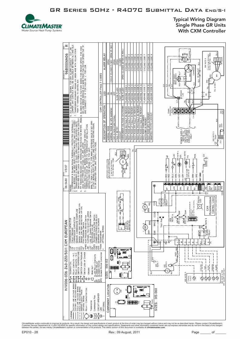
GR Series 50Hz - R407C Submittal Data Eng/S-I
Typical Wiring DiagramSingle Phase GR UnitsWith CXM Controller

ClimateMaster works continually to improve its products. As a result, the design and specifications of each product at the time of order may be changed without notice and may not be as described herein. Please contact ClimateMaster's Customer Service Department at +1-405-745-6000 for specific information on the current design and specifications. Statements and other information contained herein are not express warranties and do not form the basis of any bargain between the parties, but are merely ClimateMaster's opinion or commendation of its products. The latest version of this document is available at climatemaster.com.
Page ______ of ______Rev.: 09 August, 2011EP010 - 29
GR Series 50Hz - R407C Submittal Data Eng/S-I
Typical Wiring DiagramSingle Phase GR UnitsWith DXM Controller

ClimateMaster works continually to improve its products. As a result, the design and specifications of each product at the time of order may be changed without notice and may not be as described herein. Please contact ClimateMaster's Customer Service Department at +1-405-745-6000 for specific information on the current design and specifications. Statements and other information contained herein are not express warranties and do not form the basis of any bargain between the parties, but are merely ClimateMaster's opinion or commendation of its products. The latest version of this document is available at climatemaster.com.
Page ______ of ______Rev.: 09 August, 2011EP010 - 30
GR Series 50Hz - R407C Submittal Data Eng/S-I
Typical Wiring DiagramSingle Phase GR Units
With CXM & MPC Controller

ClimateMaster works continually to improve its products. As a result, the design and specifications of each product at the time of order may be changed without notice and may not be as described herein. Please contact ClimateMaster's Customer Service Department at +1-405-745-6000 for specific information on the current design and specifications. Statements and other information contained herein are not express warranties and do not form the basis of any bargain between the parties, but are merely ClimateMaster's opinion or commendation of its products. The latest version of this document is available at climatemaster.com.
Page ______ of ______Rev.: 09 August, 2011EP010 - 31
GR Series 50Hz - R407C Submittal Data Eng/S-I
Typical Wiring DiagramThree Phase GR UnitsWith CXM Controller

ClimateMaster works continually to improve its products. As a result, the design and specifications of each product at the time of order may be changed without notice and may not be as described herein. Please contact ClimateMaster's Customer Service Department at +1-405-745-6000 for specific information on the current design and specifications. Statements and other information contained herein are not express warranties and do not form the basis of any bargain between the parties, but are merely ClimateMaster's opinion or commendation of its products. The latest version of this document is available at climatemaster.com.
Page ______ of ______Rev.: 09 August, 2011EP010 - 32
GR Series 50Hz - R407C Submittal Data Eng/S-I
Typical Wiring DiagramThree Phase GR UnitsWith DXM Controller

ClimateMaster works continually to improve its products. As a result, the design and specifications of each product at the time of order may be changed without notice and may not be as described herein. Please contact ClimateMaster's Customer Service Department at +1-405-745-6000 for specific information on the current design and specifications. Statements and other information contained herein are not express warranties and do not form the basis of any bargain between the parties, but are merely ClimateMaster's opinion or commendation of its products. The latest version of this document is available at climatemaster.com.
Page ______ of ______Rev.: 09 August, 2011EP010 - 33
GR Series 50Hz - R407C Submittal Data Eng/S-I
General:Furnish and install ClimateMaster “Genesis” Water Source Heat Pumps, as indicated on the plans. Equipment shall be completely assembled, piped and internally wired. Capacities and characteristics as listed in the schedule and the specifications that follow.
Horizontal/Vertical Water Source Heat Pumps:Units shall be supplied completely factory built for an entering water temperature range from -6.7° to 43.3°C as standard. Equivalent units from other manufacturers can be proposed provided approval to bid is given 10 days prior to bid closing. All equipment listed in this section must be rated in accordance with (but not certified by) American Refrigeration Institute/ International Standards Organization (AHRI/ISO), and shall have CE Mark. All units shall be fully quality tested by factory run testing under normal operating conditions and water flow rates as described herein. Quality control system shall automatically perform via computer: triple leak check, pressure tests, evacuate and accurately charge system, perform detailed heating and cooling mode tests, and quality cross check all operational and test conditions to pass/fail data base. Detailed report card will ship with each unit displaying all test performance data. Note: If unit fails on any cross check, system shall not be allowed unit to ship. Serial numbers will be recorded by factory and furnished to contractor on report card for ease of unit warranty status. Units tested without water flow are not acceptable.
Basic Construction: Horizontal Units shall have one of the following air flow arrangements: Left Inlet/Straight (Right) Discharge; Right Inlet/Straight (Left) Discharge; Left Inlet/Back Discharge; or Right Inlet/Back Discharge as shown on the plans. Units must have the ability to be field convertible from straight to back or back to straight discharge with no additional parts or unit structure modification. Horizontal units will have factory installed hanger brackets with rubber isolation grommets packaged separately.
Vertical Units shall have one of the following air flow arrangements: Left Return/Top Discharge, Right Return/Top Discharge, as shown on the plans.
If units with these arrangements are not used, the contractor is responsible for any extra costs incurred by other trades. All units (horizontal and vertical) must have a minimum of three access panels for serviceability of compressor compartment. Units having only one access panel to compressor/heat exchangers/expansion device/refrigerant piping shall not be acceptable.
The heat pumps shall be fabricated from heavy gauge galvanized steel. All interior surfaces shall be lined with 12.7mm thick, dual density, 28 kg/m3 acoustic type glass fiber insulation. Insulation placement shall be designed in a manner that will eliminate any exposed edges to prevent the introduction of glass fibers into the air stream.
Vertical heat pumps shall be fabricated from heavy gauge galvanized steel with powder coat paint finish. The color will be Polar Ice. Both sides of the steel shall be painted for added protection.
Standard cabinet panel insulation must meet NFPA 90A requirements, air erosion and mold growth limits of UL-181, stringent fungal resistance test per ASTM-C1071 and ASTM G21, and shall meet zero level bacteria growth per ASTM G22. Unit insulation must meet these stringent requirements or unit(s) will not be accepted.
All horizontal units to have factory installed 25.4mm discharge air duct collars, 25.4mm filter rails with 25.4mm filters factory installed, and factory installed unit-mounting brackets. Vertical units to have field installed discharge air duct collar, shipped loose and 25.4mm filter rails with 25.4mm filters factory installed. If units with these factory installed provisions are not used, the contractor is responsible for any extra costs to field install these provisions, and/or the extra costs for his sub-contractor to install these provisions.
All units must have an insulated panel separating the fan compartment from the compressor compartment. Units with the compressor in the air stream are not acceptable. Units shall have a factory installed 25.4mm wide filter rail for filter removal from either side. Units shall have a 25.4mm thick throwaway type glass fiber filter. The contractor shall purchase one spare set of filters and replace factory shipped filters on completion of start-up. Filters shall be standard sizes. If units utilize non-standard filter sizes then the contractor shall provide 12 spare filters for each unit.
Cabinets shall have separate holes and knockouts for entrance of line voltage and low voltage control wiring. All factory-installed wiring passing through factory knockouts and openings shall be protected from sheet metal edges at openings by plastic ferrules. Supply and return water connections shall be copper FPT fittings, and shall be securely mounted flush to the cabinet corner post allowing for connection to a flexible hose without the use of a back-up wrench. Water connections that protrude through the cabinet or require the use of a backup wrench shall not be allowed. All water connections and electrical knockouts must be in the compressor compartment corner post as to not interfere with the serviceability of unit. Contractor shall be responsible for any extra costs involved in the installation of units that do not have this feature. Contractor must ensure that units can be easily removed for servicing and coordinate locations of electrical conduit and lights with the electrical contractor.
Genesis Standard (GR) SeriesEngineering Specifications Page 1

ClimateMaster works continually to improve its products. As a result, the design and specifications of each product at the time of order may be changed without notice and may not be as described herein. Please contact ClimateMaster's Customer Service Department at +1-405-745-6000 for specific information on the current design and specifications. Statements and other information contained herein are not express warranties and do not form the basis of any bargain between the parties, but are merely ClimateMaster's opinion or commendation of its products. The latest version of this document is available at climatemaster.com.
Page ______ of ______Rev.: 09 August, 2011EP010 - 34
GR Series 50Hz - R407C Submittal Data Eng/S-I
Option: Contractor shall install 50.8mm filter brackets and 50.8mm glass fiber throwaway filters on all units.
Option: UltraQuiet package shall consist of a discharge muffler (except rotary compressors) and high technology sound attenuating material that is strategically applied to the compressor and air handling compartment casings and fan scroll in addition to the standard ClimaQuiet system design, to further dampen and attenuate sound transmissions.
Option: The unit will be supplied with cupro nickel coaxial water to refrigerant heat exchanger.
Option: The unit will be supplied with internally factory mounted two-way water valve for variable speed pumping requirements. A factory-mounted or field-installed high pressure switch shall be installed in the water piping to disable compressor operation in the event water pressures build due to water freezing in the piping system.
Option: The unit will be supplied with internally factory mounted automatic water flow regulators.
Option: The unit shall be supplied with extended range Insulation option, which adds closed cell insulation to internal water lines, and provides insulation on suction side refrigeration tubing including refrigerant to water heat exchanger.
Fan and Motor Assembly:Blower shall have inlet rings to allow removal of wheel and motor from one side without removing housing. Units shall have a direct-drive centrifugal fan. The fan motor shall be 3-speed, permanently lubricated, PSC type, with internal thermal overload protection. Units supplied without permanently lubricated motors must provide external oilers for easy service. The fan motor on small and medium size units (006-042) shall be isolated from the fan housing by a torsionally flexible motor mounting system with rubber type grommets to inhibit vibration induced high noise levels associated with “hard wire belly band” motor mounting. The fan motor on larger units (048 & 060) shall be isolated with flexible rubber type isolation grommets only. The fan and motor assembly must be capable of overcoming the external static pressures as shown on the schedule. Airflow/Static pressure rating of the unit shall be based on a wet coil and a clean filter in place. Ratings based on a dry coil and / or no filter, or on an ESP less than 6.35 mm w.g. shall NOT be acceptable.
Refrigerant Circuit: Units shall have a sealed refrigerant circuit including a high efficiency scroll, rotary or reciprocating compressor designed for heat pump operation, a thermostatic expansion valve for refrigerant metering, an enhanced corrugated aluminum lanced fin and rifled copper tube refrigerant to air heat exchanger, reversing valve, coaxial (tube in tube) refrigerant to water heat exchanger, and safety controls including a high pressure switch, low pressure switch (loss of charge), water coil low temperature sensor, and air coil low temperature sensor. Access fittings shall be factory installed on high and low pressure refrigerant lines to facilitate field service. Activation of any safety device shall prevent compressor operation via a microprocessor lockout circuit. The lockout circuit shall be reset at the thermostat or at the contractor supplied disconnect switch. Units that cannot be reset at the thermostat shall not be acceptable.
Hermetic compressors shall be internally sprung. The compressor shall have a dual level vibration isolation system. The compressor will be mounted on vibration isolation springs or grommets to a large heavy gauge compressor mounting plate, which is then isolated from the cabinet base with rubber grommets for maximized vibration attenuation. Compressor shall have thermal overload protection. Compressor shall be located in an insulated compartment away from air stream to minimize sound transmission.
Refrigerant to air heat exchangers shall utilize enhanced corrugated lanced aluminum fins and rifled copper tube construction rated to withstand 3101 kPa refrigerant working pressure. Refrigerant to water heat exchangers shall be of copper inner water tube and steel refrigerant outer tube design, rated to withstand 3101 kPa working refrigerant pressure and 3101 kPa working water pressure. The refrigerant to water heat exchanger shall be “electro-coated” with a low cure cathodic epoxy material a minimum of 0.4 mils thick (0.4 – 1.5 mils range) on all surfaces. The black colored coating shall provide a minimum of 1000 hours salt spray protection per ASTM B117-97 on all external steel and copper tubing. The material shall be formulated without the inclusion of any heavy metals and shall exhibit a pencil hardness of 2H (ASTM D3363-92A), crosshatch adhesion of 4B-5B (ASTM D3359-95), and impact resistance of 184 kg-cm direct (ASTM D2794-93).
Refrigerant metering shall be accomplished by thermostatic expansion valve only. Expansion valves shall be dual port balanced types with external equalizer for optimum refrigerant metering. Units shall be designed and tested for operating ranges of entering water temperatures from -6.7° to 43.3°C. Reversing valve shall be four-way solenoid activated refrigerant valve, which shall default to heating mode should the solenoid fail to function. If the reversing valve solenoid defaults to cooling mode, an additional low temperature thermostat must be provided to prevent over-cooling an already cold room.
Drain Pan:The drain pan shall be constructed of galvanized steel and have a powder coat paint application to further inhibit corrosion. This corrosion protection system shall meet the stringent 1000 hour salt spray test per ASTM B117. If plastic type material is used, it must be HDPE (High Density Polyethylene) to avoid thermal cycling shock stress failure over the lifetime of the unit. Stainless Steel materials are also acceptable. Drain pan shall be fully insulated. Drain outlet shall be located at pan as to allow complete and unobstructed drainage of condensate. Drain outlet for horizontal units shall be connected from pan directly
Genesis Standard (GR) SeriesEngineering Specifications Page 2

ClimateMaster works continually to improve its products. As a result, the design and specifications of each product at the time of order may be changed without notice and may not be as described herein. Please contact ClimateMaster's Customer Service Department at +1-405-745-6000 for specific information on the current design and specifications. Statements and other information contained herein are not express warranties and do not form the basis of any bargain between the parties, but are merely ClimateMaster's opinion or commendation of its products. The latest version of this document is available at climatemaster.com.
Page ______ of ______Rev.: 09 August, 2011EP010 - 35
GR Series 50Hz - R407C Submittal Data Eng/S-I
to FPT fitting. No hidden internal tubing extensions from pan outlet extending to unit casing (that can create drainage problems) will be accepted. The unit as standard will be supplied with solid-state electronic condensate overflow protection. Mechanical float switches will NOT be accepted.
Vertical units shall be furnished with a PVC FPT condensate drain connection and an internal factory installed condensate trap. If units without an internal trap are used, the contractor is responsible for any extra costs to field install these provisions, and/or the extra costs for his sub-contractor to install these provisions.
Electrical: A control box shall be located within the unit compressor compartment and shall contain a 50VA transformer, 24 volt activated, 2 or 3 pole compressor contactor, terminal block for thermostat wiring and solid-state controller for complete unit operation. Reversing valve and fan motor wiring shall be routed through this electronic controller. Units shall be name-plated for use with time delay fuses or HACR circuit breakers. Unit controls shall be 24 Volt and provide heating or cooling as required by the remote thermostat / sensor.
Solid State Control System (CXM): Units shall have a solid-state control system. Units utilizing electro-mechanical control shall not be acceptable. The control system microprocessor board shall be specifically designed to protect against building electrical system noise contamination, EMI, and RFI interference. The control system shall interface with a heat pump type thermostat. The control system shall have the following features:
a. Anti-short cycle time delay on compressor operation.b. Random start on power up mode.c. Low voltage protection.d. High voltage protection.e. Unit shutdown on high or low refrigerant pressures.f. Unit shutdown on low water temperature.g. Condensate overflow electronic protection.h. Option to reset unit at thermostat or disconnect.i. Automatic intelligent reset. Unit shall automatically reset the unit 5 minutes after trip if the fault has cleared. If a fault
occurs 3 times sequentially without thermostat meeting temperature, then lockout requiring manual reset will occur.j. Ability to defeat time delays for servicing.k. Light emitting diode (LED) on circuit board to indicate high pressure, low pressure, low voltage, high voltage, low water/
air temperature cut-out, condensate overflow, and control voltage status.l. The low-pressure switch shall not be monitored for the first 120 seconds after a compressor start command to prevent
nuisance safety trips.m. 24V output to cycle a motorized water valve or other device with compressor contactor.n. Unit Performance Sentinel (UPS). The UPS warns when the heat pump is running inefficiently.o. Water coil low temperature sensing (selectable for water or anti-freeze).p. Air coil low temperature sensing.
NOTE: Units not providing the 8 safety protections of anti-short cycle, low voltage, high voltage, high refrigerant pressure, low pressure (loss of charge), air coil low temperature cut-out, water coil low temperature cut-out, and condensate overflow protections will not be accepted.
Option: Enhanced solid state control system (DXM)This control system features two stage control of cooling and two stage control of heating modes for exacting temperature and dehumidification purposes.
This control system coupled with a multi-stage thermostat will better dehumidify room air by automatically running the heat pump’s fan at lower speed on the first stage of cooling thereby implementing low sensible heat ratio cooling. On the need for higher cooling performance the system will activate the second stage of cooling and automatically switch the fan to the higher fan speed setting. This system may be further enhanced with a humidistat. Units not having automatic low sensible heat ratio cooling will not be accepted; as an alternate a hot gas reheat coil may be provided with control system for automatic activation.
Control shall have all of the above mentioned features of the CXM control system along with the following expanded features:
a. Removable thermostat connector.b. Night setback control.c. Random start on return from night setback.d. Minimized reversing valve operation (Unit control logic shall only switch the reversing valve when cooling is demanded for
the first time. The reversing valve shall be held in this position until the first call for heating, ensuring quiet operation and increased valve life.).
e. Override temperature control with 2-hour timer for room occupant to override setback temperature at the thermostat.f. Dry contact night setback output for digital night setback thermostats.
Genesis Standard (GR) SeriesEngineering Specifications Page 3

ClimateMaster works continually to improve its products. As a result, the design and specifications of each product at the time of order may be changed without notice and may not be as described herein. Please contact ClimateMaster's Customer Service Department at +1-405-745-6000 for specific information on the current design and specifications. Statements and other information contained herein are not express warranties and do not form the basis of any bargain between the parties, but are merely ClimateMaster's opinion or commendation of its products. The latest version of this document is available at climatemaster.com.
Page ______ of ______Rev.: 09 August, 2011EP010 - 36
GR Series 50Hz - R407C Submittal Data Eng/S-I
g. Ability to work with heat pump or heat/cool (Y, W) type thermostats.h. Ability to work with heat pump thermostats using O or B reversing valve control.i. Emergency shutdown contacts.j. Boilerless system heat control at low loop water temperature.k. Ability to allow up to 3 units to be controlled by one thermostat.l. Relay to operate an external damper.m. Ability to automatically change fan speed from multistage thermostat.n. Relay to start system pump.o. 75 VA control transformer. Control transformer shall have load side short circuit and overload protection via a built in
circuit breaker.
Remote Service Sentinel (CXM/DXM):Solid state control system shall communicate with thermostat to display (at the thermostat) the unit status, fault status, and specific fault condition, as well as retrieve previously stored fault that caused unit shutdown. The Remote Service Sentinel allows building maintenance personnel or service personnel to diagnose unit from the wall thermostat. The control board shall provide a signal to the thermostat fault light, indicating a lockout. Upon cycling the G (fan) input 3 times within a 60 second time period, the fault light shall display the specific code as indicated by a sequence of flashes. A detailed flashing code shall be provided at the thermostat LED to display unit status and specific fault status such as over/under voltage fault, high pressure fault, low pressure fault, low water temperature fault, condensate overflow fault, etc. Units that do not provide this remote service sentinel shall not be acceptable.
Option: Lonworks interface systemUnits shall have all the features listed above (either CXM or DXM) and the control board will be supplied with a LONWORKS interface board, which is LONMark certified. This will permit all units to be daisy chained via a 2-wire twisted pair shielded cable. The following points must be available at a central or remote computer location: a. Space temperature b. Leaving water temperaturec. Discharge air temperatured. Command of space temperature setpointe. Cooling statusf. Heating statusg. Low temperature sensor alarmh. Low pressure sensor alarmi. High pressure switch alarmj. Condensate sensor alarmk. Hi/low voltage alarml. Fan “ON/AUTO” position of space thermostat as specified abovem. Unoccupied / occupied commandn. Cooling commando. Heating commandp. Fan “ON / AUTO” commandq. Fault reset commandr. Itemized fault code revealing reason for specific shutdown fault (any one of 7)
This option also provides the upgraded 75VA control transformer with load side short circuit and overload protection via a built in circuit breaker.
Option: MPC (Multiple Protocol Control) interface system Units shall have all the features listed above (either CXM or DXM) and the control board will be supplied with a Multiple Protocol interface board. Available protocols are BACnet MS/TP, Modbus, or Johnson Controls N2. The choice of protocol shall be field selectable/changeable via the use of a simple selector switch. Protocol selection shall not require any additional programming or special external hardware or software tools. This will permit all units to be daisy chain connected by a 2-wire twisted pair shielded cable. The following points must be available at a central or remote computer location: a. Space temperature b. Leaving water temperaturec. Discharge air temperatured. Command of space temperature setpointe. Cooling statusf. Heating statusg. Low temperature sensor alarmh. Low pressure sensor alarmi. High pressure switch alarmj. Condensate overflow alarmk. Hi/low voltage alarml. Fan “ON/AUTO” position of space thermostat as specified above
Genesis Standard (GR) SeriesEngineering Specifications Page 4

ClimateMaster works continually to improve its products. As a result, the design and specifications of each product at the time of order may be changed without notice and may not be as described herein. Please contact ClimateMaster's Customer Service Department at +1-405-745-6000 for specific information on the current design and specifications. Statements and other information contained herein are not express warranties and do not form the basis of any bargain between the parties, but are merely ClimateMaster's opinion or commendation of its products. The latest version of this document is available at climatemaster.com.
Page ______ of ______Rev.: 09 August, 2011EP010 - 37
GR Series 50Hz - R407C Submittal Data Eng/S-I
m. Unoccupied / occupied commandn. Cooling commando. Heating commandp. Fan “ON / AUTO” commandq. Fault reset commandr. Itemized fault code revealing reason for specific shutdown fault (any one of 7)
This option also provides the upgraded 75VA control transformer with load side short circuit and overload protection via a built in circuit breaker.
Warranty:Climate Master shall warranty equipment for a period of 12 months from start up or 18 months from shipment (whichever occurs first).
Option: Extended 4-year compressor warranty covers compressor for a total of 5 years.
Option: Two-Year Extended Warranty provides coverage for a period of 30 months from date of shipment or 24 months from the date of start-up (whichever occurs first).
FIELD INSTALLED OPTIONS
Hose Kits: All units 35 kW and below shall be connected with hoses. The hoses shall be 61cm long, braided stainless steel; fire rated hoses complete with adapters. Only fire rated hoses will be accepted.
Valves:The following valves are available and will be shipped loose:a. Ball valve; bronze material, standard port full flow design, FPT connections.b. Ball valve with memory stop and PT port.c. “Y” strainer with blowdown valve; bronze material, FPT connections.d. Motorized water valve; slow acting, 24v, FPT connections.
Hose Kit Assemblies:The following assemblies ship with the valves already assembled to the hose described:a. Supply and return hoses having ball valve with PT port.b. Supply hose having ball valve with PT port; return hose having automatic flow regulator valve with PT ports, and ball valve.c. Supply hose having “Y” strainer with blowdown valve, and ball valve with PT port; return hose having automatic flow
regulator with PT ports, and ball valve.d. Supply hose having “Y” strainer with blowdown valve, and ball valve with PT port; return hose having ball valve with PT port.
Thermostats:The thermostat shall be a ClimateMaster mechanical or electronic type thermostat as selected below with the described features: a. Single Stage Standard Manual Changeover (ATM11C11) Thermostat shall be a single-stage, horizontal mount, manual changeover with HEAT-OFF-COOL system switch and fan
ON-AUTO switch. Thermostat shall have a mechanical temperature set point indicator. Thermostat shall only require 4 wires for connection. Mercury bulb thermostats are not acceptable.
b. Single Stage Digital Auto or Manual Changeover (ATA11U01) Thermostat shall be a single-stage, digital, auto or manual changeover with HEAT-OFF-COOL-AUTO system switch and
fan ON-AUTO switch. Thermostat shall have an LCD display with temperature and set-point(s) in ºF or ºC. The Thermostat shall provide permanent memory of set-point(s) without batteries. A fault LED shall be provided to display specific fault condition. Thermostat shall provide temperature display offset for custom applications.
c. Single Stage Digital Automatic or Manual Changeover with Two-Speed Fan Control (ATA11C04) – DXM and PSC Fan required
Thermostat shall be a single-stage, digital, auto or manual changeover with HEAT-OFF-COOL-AUTO system switch, fan ON-AUTO switch, and fan LO-HI switch. Thermostat shall have an LCD display with temperature and set-point(s) in ºF or ºC. A fault LED shall be provided to display specific fault condition. Thermostat shall allow use of an accessory remote temperature sensor (AST009), but may be operated with internal sensor via orientation of a jumper.
Genesis Standard (GR) SeriesEngineering Specifications Page 5

ClimateMaster works continually to improve its products. As a result, the design and specifications of each product at the time of order may be changed without notice and may not be as described herein. Please contact ClimateMaster's Customer Service Department at +1-405-745-6000 for specific information on the current design and specifications. Statements and other information contained herein are not express warranties and do not form the basis of any bargain between the parties, but are merely ClimateMaster's opinion or commendation of its products. The latest version of this document is available at climatemaster.com.
Page ______ of ______Rev.: 09 August, 2011EP010 - 38
GR Series 50Hz - R407C Submittal Data Eng/S-I
d. Single Stage Digital Automatic Changeover (ATA11C06) Thermostat shall be a single-stage, digital, auto or manual changeover with HEAT-OFF-COOL-AUTO system switch and
fan ON-AUTO switch. Thermostat shall have an LCD display with temperature and set-point(s) in ºF or ºC. A fault LED shall be provided to display specific fault condition. Thermostat shall allow use of an accessory remote temperature sensor (AST009), but may be operated with internal sensor via orientation of a jumper.
e. Multistage Digital Automatic Changeover (ATA22U01) Thermostat shall be multi-stage (2H/2C), manual or automatic changeover with HEAT-OFF-COOL-AUTO-EM HEAT
system settings and fan ON-AUTO settings. Thermostat shall have an LCD display with temperature, set-point(s), mode, and status indication. The temperature indication shall be selectable for ºF or ºC. The thermostat shall provide permanent memory of set-point(s) without batteries. A fault LED shall be provided to indicate specific fault condition(s). Thermostat shall provide temperature display offset for custom applications. Thermostat shall allow unit to provide better dehumidification with optional DXM controller by automatically using lower fan speed on stage 1 cooling (higher latent cooling) as main cooling mode, and automatically shifting to high speed fan on stage 2 cooling.
f. Multistage Manual Changeover Programmable 5/2 Day (ATP21U01) Thermostat shall be 5 day/2 day programmable (with up to 4 set points per day), multi-stage (2H/1C), manual changeover
with HEAT-OFF-COOL-EM HEAT system settings and fan ON-AUTO settings. Thermostat shall have an LCD display with temperature, set-point(s), mode, and status indication. The temperature indication shall be selectable for ºF or ºC. The thermostat shall provide permanent memory of set-point(s) without batteries. Thermostat shall provide convenient override feature to temporarily change set point.
g. Multistage Automatic or Manual Changeover Programmable 7 Day (ATP32U03) Thermostat shall be 7 day programmable (with up to 4 set points per day), multi-stage (3H/2C), automatic or manual
changeover with HEAT-OFF-COOL-AUTO-EM HEAT system settings and fan ON-AUTO settings. Thermostat shall have a blue backlit dot matrix LCD display with temperature, set-points, mode, and status indication. The temperature indication shall be selectable for ºF or ºC. Time display shall be selectable for 12 or 24 hour clock. Fault identification shall be provided (when used with ClimateMaster CXM or DXM controls) to simplify troubleshooting by providing specific unit fault at the thermostat with red backlit LCD during unit lockout. The thermostat shall provide permanent memory of set-points without batteries. Thermostat shall provide heating set-point range limit, cooling set-point range limit, temperature display offset, keypad lockout, dead-band range setting, and inter-stage differential settings. Thermostat shall provide progressive recovery to anticipate time required to bring space temperature to the next programmed event. Thermostat shall provide an installer setup for configuring options and for setup of servicing contractor name and contact information. Thermostat shall allow the use of an accessory remote and/or outdoor temperature sensor (AST008). Thermostat navigation shall be accomplished via five buttons (up/down/right/left/select) with menu-driven selections for ease of use and programming.
h. Multistage Automatic or Manual Changeover Programmable 7 Day with Humidity Control (ATP32U04) Thermostat shall be 7 day programmable (with up to 4 set points per day), multi-stage (3H/2C), automatic or
manual changeover with HEAT-OFF-COOL-AUTO-EM HEAT system settings and fan ON-AUTO settings. Separate dehumidification and humidification set points shall be configurable for discreet outputs to a dehumidification option and/or an external humidifier. Installer configuration mode shall allow thermostat dehumidification mode to operate with ClimaDry reheat or with ECM fan dehumidification mode via settings changes. Thermostat shall have a blue backlit dot matrix LCD display with temperature, relative humidity, set-points, mode, and status indication. The temperature indication shall be selectable for ºF or ºC. Time display shall be selectable for 12 or 24 hour clock. Fault identification shall be provided (when used with ClimateMaster CXM or DXM controls) to simplify troubleshooting by providing specific unit fault at the thermostat with red backlit LCD during unit lockout. The thermostat shall provide permanent memory of set-points without batteries. Thermostat shall provide heating set-point range limit, cooling set-point range limit, temperature display offset, keypad lockout, dead-band range setting, and inter-stage differential settings. Thermostat shall provide progressive recovery to anticipate time required to bring space temperature to the next programmed event. Thermostat shall provide an installer setup for configuring options and for setup of servicing contractor name and contact information. Thermostat shall allow the use of an accessory remote and/or outdoor temperature sensor (AST008). Thermostat navigation shall be accomplished via five buttons (up/down/right/left/select) with menu-driven selections for ease of use and programming.
DDC Sensors:ClimateMaster wall mounted DDC sensor to monitor room temperature and interfaces with optional interface system described above. Several types as described below:a. Sensor only with no display (LON and MPC).b. Sensor with override (LON only).c. Sensor with setpoint adjustment and override (MPC only).d. Sensor with setpoint adjustment and override, LCD display, status/fault indication (LON and MPC).
Genesis Standard (GR) SeriesEngineering Specifications Page 6

ClimateMaster works continually to improve its products. As a result, the design and specifications of each product at the time of order may be changed without notice and may not be as described herein. Please contact ClimateMaster's Customer Service Department at +1-405-745-6000 for specific information on the current design and specifications. Statements and other information contained herein are not express warranties and do not form the basis of any bargain between the parties, but are merely ClimateMaster's opinion or commendation of its products. The latest version of this document is available at climatemaster.com.
Page ______ of ______Rev.: 09 August, 2011EP010 - 39
GR Series 50Hz - R407C Submittal Data Eng/S-I
Notes:

ClimateMaster works continually to improve its products. As a result, the design and specifications of each product at the time of order may be changed without notice and may not be as described herein. Please contact ClimateMaster's Customer Service Department at +1-405-745-6000 for specific information on the current design and specifications. Statements and other information contained herein are not express warranties and do not form the basis of any bargain between the parties, but are merely ClimateMaster's opinion or commendation of its products. The latest version of this document is available at climatemaster.com.
Page ______ of ______Rev.: 09 August, 2011EP010 - 40
GR Series 50Hz - R407C Submittal Data Eng/S-I
Date: Item: Action:08/09/11 Unit Maximum Working Water Pressure Updated to Reflect New Safeties
09/28/10 Engineering Specifications Updated
08/05/10 Entire Document Removed I-P UnitsUpdated Engineering Specification Options
06/12/08 Engineering Specifications Verbiage Updates
11/20/07 First Published
Revision History
Top Related