


Languages
Pages
Legal


GENERAL ELECTRIC
AIR COOLEDSCREW WATER CHILLERSR-134a
AASC Series AASC055B thru AASC445B 55 TR thru 445 TR | | | 194 kW thru 1565 kW
GE_AASC_Series.indd 1 3/26/12 5:20 PM

GE_AASC_Series.indd 2 3/26/12 5:20 PM
1
Model decoding . . . . . . . . . . . . . . . . . . . . . . . . . . . . . . . . . . . . . . . . . . . . . . . . . . . . . . . . . . . . . . . . . . . . . . . . . . . . 2
Unit features, standard specifi cations & options . . . . . . . . . . . . . . . . . . . . . . . . . . . . . . . . . . . . . . . . . . . . . 3-7
Physical data . . . . . . . . . . . . . . . . . . . . . . . . . . . . . . . . . . . . . . . . . . . . . . . . . . . . . . . . . . . . . . . . . . . . . . . . . . . 8-11
Selection procedure . . . . . . . . . . . . . . . . . . . . . . . . . . . . . . . . . . . . . . . . . . . . . . . . . . . . . . . . . . . . . . . . . . . . . 12-13
Ethylene glycol solution capacity correction . . . . . . . . . . . . . . . . . . . . . . . . . . . . . . . . . . . . . . . . . . . . . . . . . 14
Performance data . . . . . . . . . . . . . . . . . . . . . . . . . . . . . . . . . . . . . . . . . . . . . . . . . . . . . . . . . . . . . . . . . . . . . . 15-20
Electrical data . . . . . . . . . . . . . . . . . . . . . . . . . . . . . . . . . . . . . . . . . . . . . . . . . . . . . . . . . . . . . . . . . . . . . . . . . . . . 21
Water side pressure drop . . . . . . . . . . . . . . . . . . . . . . . . . . . . . . . . . . . . . . . . . . . . . . . . . . . . . . . . . . . . . . . . . . 22
Unit dimensions . . . . . . . . . . . . . . . . . . . . . . . . . . . . . . . . . . . . . . . . . . . . . . . . . . . . . . . . . . . . . . . . . . . . . . . 23-28
Typical schematic wiring diagram . . . . . . . . . . . . . . . . . . . . . . . . . . . . . . . . . . . . . . . . . . . . . . . . . . . . . . . 29-31
Microprocessor controller . . . . . . . . . . . . . . . . . . . . . . . . . . . . . . . . . . . . . . . . . . . . . . . . . . . . . . . . . . . . . . 32-34
Application guidelines . . . . . . . . . . . . . . . . . . . . . . . . . . . . . . . . . . . . . . . . . . . . . . . . . . . . . . . . . . . . . . . . . 35-44
Rigging instructions . . . . . . . . . . . . . . . . . . . . . . . . . . . . . . . . . . . . . . . . . . . . . . . . . . . . . . . . . . . . . . . . . . . . . . 45
Installation clearance . . . . . . . . . . . . . . . . . . . . . . . . . . . . . . . . . . . . . . . . . . . . . . . . . . . . . . . . . . . . . . . . . . . . . 46
Mounting location . . . . . . . . . . . . . . . . . . . . . . . . . . . . . . . . . . . . . . . . . . . . . . . . . . . . . . . . . . . . . . . . . . . . . . . . 47
Load distribution . . . . . . . . . . . . . . . . . . . . . . . . . . . . . . . . . . . . . . . . . . . . . . . . . . . . . . . . . . . . . . . . . . . . . . 48-49
Continuing research results in steady improvements. Therefore, these specifi cations are subject to change without notice
CONTENTS
GE_AASC_Series.indd 1 3/26/12 5:20 PM

2
MODEL DECODING & PRODUCT INFORMATION
GE_AASC_Series.indd 2 3/26/12 5:20 PM
AA
SC
GE
AIR
CO
OLE
D
SCRE
W W
ATE
R
CH
ILLE
RS
9EL
ECTR
ICA
LSU
PPLY
( V-P
h-H
z)
5, 6
& 7
UN
IT S
IZE
055
060
070
075
090
100
110
120
130
140
150
170
185
200
215
240
255
275
300
315
330
350
370
405
445
L:3
80/4
15-3
-50
(4
WIR
E)
1, 2
, 3 &
4
B
ASI
C
(SER
IES)
B: R
-134
a
8
REF
RIG
ER-
ANT
10 C
ON
DEN
SER
CO
IL
A :
ALU
MIN
UM
FIN
B :
PRE-
COA
TED
ALU
MIN
UM
FIN
C :
CO
PPER
FIN
D :
COAT
EDAL
UM
INU
M F
INW
ITH
THER
MO
GU
ARD
E:
COAT
EDC
OPP
ER F
IN W
ITH
THER
MO
GU
ARD
(SEE
NO
TE #
1
BELO
W)
11C
IRC
UIT
BR
EAK
ER
OPT
ION
S
12C
OO
LER
OPT
ION
S
A:S
TAN
DA
RD
WIT
HVI
CTA
ULI
C C
ON
N.
B:F
LAN
GE
CO
NN
(O
PTIO
NA
L)
C:A
SME
STA
MPE
DW
ITH
VIC
TAU
LIC
C
ON
N.
(OPT
ION
AL)
D:A
SME
STA
MPE
DW
ITH
FLA
NG
EC
ON
N.(
OPT
ION
AL)
A:C
OM
PRES
SOR
CIR
CU
IT
BREA
KER
13C
OM
PRES
SOR
OPT
ION
S
14H
GB
PO
PTIO
NS
A:S
TAN
DA
RD U
NIT
W
ITH
OU
T SU
CTI
ON
SERV
ICE
VALV
E
B
: UN
IT W
ITH
SU
CTI
ON
SER
VIC
E VA
LVE
(O
PTIO
N)
A
: STA
ND
ARD
UN
IT
WIT
HO
UT
HG
BP &
W
ITH
OU
T SU
CTI
ON
SER
VIC
E VA
LVE
B
: W
ITH
HG
BP &
W
ITH
OU
T SU
CTI
ON
SE
RVIC
E VA
LVE
(O
PTIO
N)
C
: W
ITH
OU
T H
GBP
&
WIT
H S
UC
TIO
N
SERV
ICE
VALV
E
(OPT
ION
)
D
: W
ITH
HG
BP &
W
ITH
SU
CTI
ON
SER
VIC
E VA
LVE
(O
PTIO
N)
14 &
15
OPT
ION
S&
AC
CES
SOR
IES
SEE
NO
TE #
2
BELO
W
NO
TES:
1. F
OR
OTH
ER C
OA
TIN
G, S
PEC
IFY
YOU
R RE
QU
IREM
ENTS
IN W
RITI
NG
.2.
CO
MPU
TER
SELE
CTE
D D
IGIT
S (F
ROM
‘AA
’ TO
‘ZZ'
) DES
CRI
BIN
G O
THER
OPT
ION
S &
AC
CES
SORI
ES O
R C
OM
BIN
ATI
ON
S TH
EREO
F, S
UC
H A
S'
- CO
ND
ENSE
R C
OIL
GU
ARD
- CO
OLE
R G
UA
RD- U
NIT
DIS
CO
NN
ECT
SWIC
H- C
OM
PRES
SOR
ENC
LOSU
RE- W
ATE
R FL
OW
SW
ITC
H- S
PRIN
G IS
OLA
TOR
- MU
LTI-
Resi
sTec
PIP
ING
- MU
LTI-
Resi
sTec
SH
EET
MET
AL
etc.
..
:

3
FEATURESThese AASC air cooled screw water chillers off er the ultimate combination of energy saving design, superior engineering features and fl exibility of application as required by today’s market.
Wide size range for every application need.
Equipped with the advanced controller from Microprocessor Control System (MCS) as standard. This controller monitors both analog and digital inputs in order to achieve precise control and full protective functions of the air cooled water chiller. It has the complete hardware and software necessary to control the chiller and to ensure the highest energy efficiency and reliability.
Designed to conform to ARI standard 550/590 water chilling packages using the vapor compression cycle. Designed to conform to ANSI/ASHRAE 15-1994 Safety code for Mechanical Refrigeration.
Compact unit design and excellent serviceability.
All packaged chillers incorporate compact water coolers with enhanced inner grooved copper tubes expanded into a steel tubular sheets which offer efficient water flow as well as heat transfer design that results in optimal unit performance.
High Energy Efficiency Ratio (EER) semi-hermetic compact twin screw compressors.
Single point power connection to minimize job site installation cost and time.
Complete factory wired control panel for all compressor motor starters, fan motor starters and microprocessor controller that provides all necessary operating and full safety control.
Compressor motors are with part winding start or star delta start.
Low noise condenser fans, direct drive at 940 RPM with rolled form venturi design to eliminate short circuiting of airflow.
All fans are high quality aluminum propeller type with aerodynamic design, top discharge, provided with protective grille mounted on top panel within the unit casing.
All condenser fan motors are totally enclosed air over type (TEAO) with class ‘’F’’ winding insulation and ball bearings. Inherent thermal protection of the automatic reset type and specially designed for outdoor application..
STANDARD SPECIFICATIONSCABINET
All units are of heavy gauge (G-90) galvanized steel. The steel sheet panels are zinc coated and galvanized by hot dip process of lock-forming quality conforming to ASTM A 653 commercial weight G-90 followed by air dry paint or backed on electrostatic polyester dry powder coat.
CAPACITY CONTROL
These chillers are equipped with stepless capacity control system as standard for very accurate response to load requirements and best part load effi ciency. Each compressor is equipped with a slider controller that enables to modulate capacity between 25% to 100%, thus giving a broad range to control total chiller capacity between 10% to 100% on an average. This system has following advantages:
1. Infinite capacity modulation that allows the compressor capacity to exactly match the cooling load.
2. Reduces compressor cycling that leads to better operational reliability.
3. Reduces operating cost.
4. For units with Hot gas bypass (optional): The unit modulates to approximately 50% of its compressor lowest unloaded capacity.
UNIT FEATURES, STANDARD SPECIFICATIONS & OPTIONS
GE_AASC_Series.indd 3 3/26/12 5:20 PM
4
UNIT FEATURES, STANDARD SPECIFICATIONS & OPTIONS
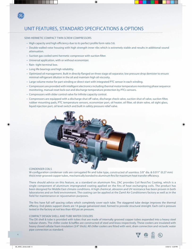
SEMI-HERMETIC COMPACT TWIN SCREW COMPRESSORS
High capacity and high efficiency due to its perfect profile form ratio 5:6.
Double-walled rotor housing with high strength inner ribs which is extremely stable and results in additional sound attenuation.
Suction gas cooled semi-hermetic compressor with suction filter.
Universal application, with or without economizer.
Rain- tight terminal box.
Long life bearings and high reliability.
Optimized oil management. Built in directly flanged on three stage oil separator, low pressure drop demister to ensure minimal refrigerant dilution in the oil and maintain high oil viscosity.
Large volume motor for part winding or direct start with integrated PTC sensor in each winding.
Compressors are provided with intelligent electronics including thermal motor temperature monitoring phase sequence monitoring, manual reset lock-out and discharge temperature protection by PTCs sensors.
Compressors with slider control valve for Infinite capacity control.
Compressors are equipped with a discharge shut off valve, discharge check valve, suction shut of valve, suction filter, rubber mounting pads, PTC temperature sensors, economizer port, oil heater, oil filter, oil drain valve, oil sight glass, liquid injection port, oil level switch and built in safety pressure relief valve.
GE_AASC_Series.indd 4 3/26/12 5:20 PM
CONDENSER COILSW-confi guration condenser coils are corrugated fi n and tube type, constructed of seamless 3/8” dia. & 0.011” (0.27 mm)thick inner grooved copper tubes, mechanically bonded to aluminum fi ns for maximum heat transfer effi ciency.
There should advice on this feature, as a standard on aluminum fins, ZAC provides Coil ResisTec Coating, which is a single component of aluminum impregnated coating applied on the fins of heat exchanging coils. The product has been designed for Middle East climate conditions. A high chemical, abrasion and UV resistance has been proven in both laboratories and on field environment. The coating can be applied at the Zamil Air Conditioners factory as well as in the field for maintenance or rejuvenation purposes.
The fins have full self spacing collars which completely cover each tube. The staggered tube design improves the thermal effiency. End plates support sheets are 14 gauge galvanized steel, formed to provide structural strenght. Each coil is pressure tested in the factory at not less than 450 psi air pressure.
COMPACT DESIGN SHELL AND TUBE WATER COOLERSThe DX shell & tube is provided with tubes that are made of internally grooved copper tubes expanded into a heavy steel tubular sheets. The chiller cooler & baffl es are constructed of steel and brass respectively. These coolers are insulated with heavy closed cellular foam insulation (3/4” thick). All chiller coolers are fi tted with vent, drain connection and victaulic water pipe connection as standard.
5
UNIT FEATURES, STANDARD SPECIFICATIONS & OPTIONS
CONTROL PANEL
The control panel design is equivalent to NEMA 4 (IP55) with hinged door for easy access ensuring dust and weather- proof construction. Internal power and control wiring is neatly routed, adequately anchored and all wires identifi ed with cable markers as per NEC standards applicable to HVAC industry. The electrical controls used in the control panel are UL approved which are reliable in operation at high ambient conditions for a long period.
CONDENSER FANS
Condenser fans, the impeller and motors are so constructed to form an integral unit. All fan motors shall be three phase with class ‘’F’’ winding insulation and ball bearings for high ambient application. These fan motors are of totally enclosed air over type (TEAO) with inherent thermal protection of automatic reset type.
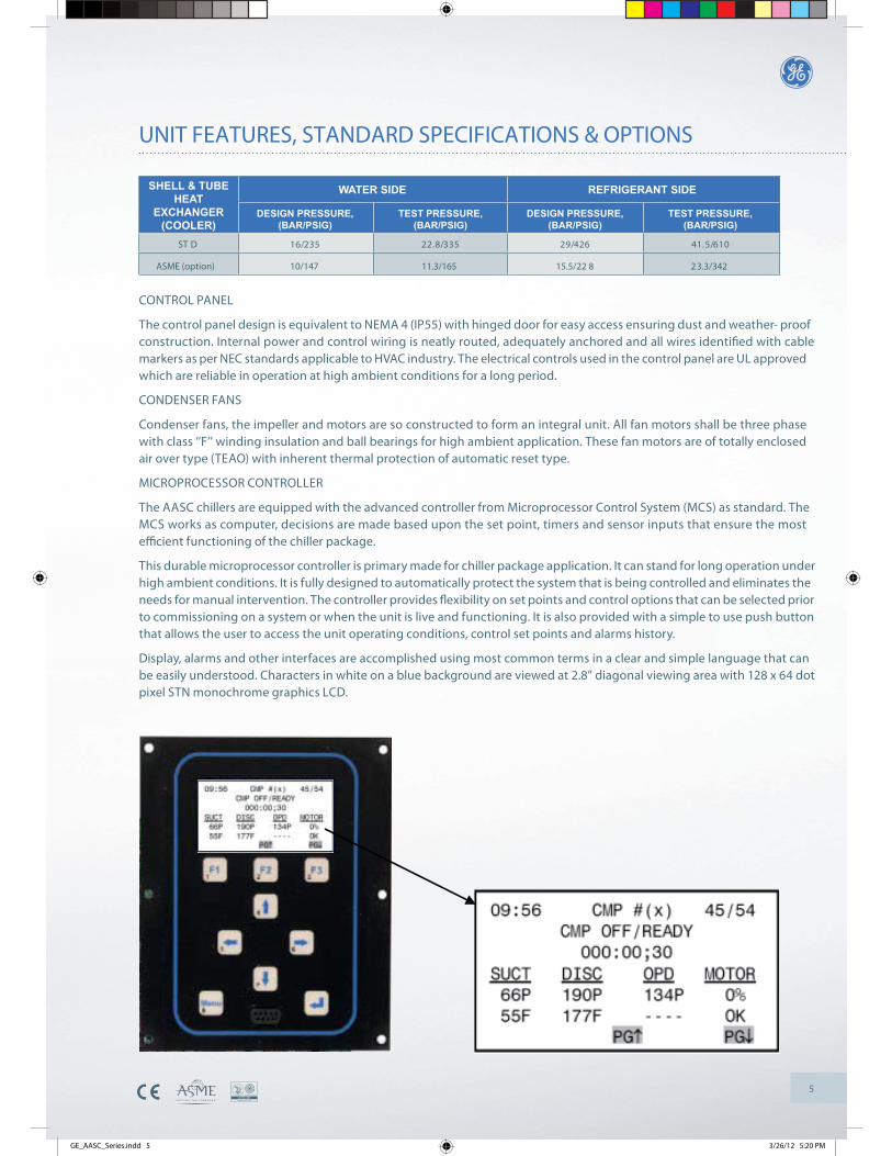
MICROPROCESSOR CONTROLLER
The AASC chillers are equipped with the advanced controller from Microprocessor Control System (MCS) as standard. The MCS works as computer, decisions are made based upon the set point, timers and sensor inputs that ensure the most effi cient functioning of the chiller package.
This durable microprocessor controller is primary made for chiller package application. It can stand for long operation under high ambient conditions. It is fully designed to automatically protect the system that is being controlled and eliminates the needs for manual intervention. The controller provides fl exibility on set points and control options that can be selected prior to commissioning on a system or when the unit is live and functioning. It is also provided with a simple to use push button that allows the user to access the unit operating conditions, control set points and alarms history.
Display, alarms and other interfaces are accomplished using most common terms in a clear and simple language that can be easily understood. Characters in white on a blue background are viewed at 2.8” diagonal viewing area with 128 x 64 dot pixel STN monochrome graphics LCD.
EDIS TNAREGIRFEREDIS RETAW
DESIGN PRESSURE,(BAR/PSIG)
TEST PRESSURE,(BAR/PSIG)
DESIGN PRESSURE,(BAR/PSIG)
TEST PRESSURE,(BAR/PSIG)
SHELL & TUBEHEAT
EXCHANGER(COOLER)
016/5.14624/92533/8.22532/61ST D
10/147 11.3/165 15.5/22 8 23.3/342ASME (option)
GE_AASC_Series.indd 5 3/26/12 5:20 PM
6
UNIT FEATURES, STANDARD SPECIFICATIONS & OPTIONS
STANDARD CONTROL & SAFETY DEVICES MICROPROCESSOR CONTROLLER: This controller monitors analog and digital inputs to achieve precise control & safety functions of the unit.
COMPRESSOR IN-BUILT PROTECTION DEVICE: Protects the compressor by monitoring:
A) Motor winding temperature in case of overload.
B) Discharge gas temperature in case of overheating.
C) Phase reversal for direction of rotation.
STARTERS: The part winding or star delta starter is operated by the control circuit and provides power to the compressor motors. These devices are rated to safely handle both RLA and LRA of motors.
CRANKCASE HEATERS: Each compressor has immersion type crankcase heater. The compressor crankcase heater is always on when the compressors are de-energized. This protect the system against refrigerant migration, oil dilution and potential compressor failure.
HIGH PRESSURE SWITCH: This switch provides an additional safety protection in the case of excessive discharge pressure.
STANDARD ACCESSORIES UNIT ON-OFF SWITCH: ON-OFF switch is provided for manually switching the unit control circuit.
INDICATOR LIGHTS: LED lights indicates power ON to the units, MENU adjustment and FAULT indications due to trip on safety devices.
ELECTRONIC EXPANSION VALVE: Electronic expansion valve is used to regulate the refrigerant fl ow to the water cooler and maintain a constant superheat and load optimization.
FILTER DRIER (REPLACEABLE CORE TYPE): Refrigerant circuits are kept free of harmful moisture, sludge, acids and oil contaminating particles by the fi lter drier.
SIGHT GLASS: A moisture indicating sight glass installed in the liquid line. An easy-to-read color indicator shows moisture contents and provides a mean for checking the system refrigerant charge.
LIQUID LINE SOLENOID VALVE: Closes when the compressor is off to prevent any liquid refrigerant from accumulating in the water cooler during the off cycle.
UNDER VOLTAGE AND PHASE PROTECTION: Protects against low incoming voltage as well as single phasing, phase reversal and phase imbalance by de-energizing the control circuit. It is an automatic reset device, but it can be set up for manual reset.
COMPRESSOR CIRCUIT BREAKERS: Protects against compressor branch circuit fault. When tripped (manually or automatically), the breaker opens the power supply to the compressor and control circuit through auxiliary contacts.
OPTIONSHOT GAS BYPASS SYSTEM: Hot gas bypass is provided on the lead circuit to permit operation of the system down to 50% of its unloaded capacity. Under low ambient condition, it controls temperature by eliminating the need to cycle the compressor on and off , ensuring narrow temperature swing and lengthen the life span of the compressor.
WATER FLOW SWITCH: Paddle type fi eld adjustable fl ow switch for water cooler circuits. Interlock into unit safety circuits so that the unit will remain off until water fl ow is determine.
UNIT MOUNT SPRING ISOLATORS: This housed spring assemblies have a neoprene friction pad on the bottom to prevent vibration transmission.
LIQUID COOLERS: ASME code stamped liquid cooler.
PRESSURE GAUGES: Suction & discharge pressures gauges.
NON-FUSED MAIN DISCONNECT SWITCHES: De-energize power supply during servicing/repair works as well as with door interlock.
GE_AASC_Series.indd 6 3/26/12 5:20 PM
7
UNIT FEATURES, STANDARD SPECIFICATIONS & OPTIONS
CONDENSER COIL GUARD: Protects the condenser coil from physical damage.
COMPRESSOR/COOLER GUARD: Protects the compressor and cooler from vandalism.
COMPRESSOR ENCLOSURE BOX: Reduces compressor operating noise and keeps the compressor clean.
FLANGED COOLER CONNECTION: Easy on-site piping connections.
COOLER HEATER WRAPPED : Prevents freezing up of water on low ambient temperature.
COPPER FINS/TUBES CONDENSER COILS : For seashore salty corrosive environments.
COATED COPPER/ALUMINUM FINS CONDENSER COILS : For seashore or acid corrosive environments.
ResisTec COATED COPPER FINS/TUBES CONDENSER COILS: For seashore or acid corrosive environments.
BMS: BACNET, MODBUS, Johnson control and LON work.
MULTI ResisTec : A two component coating system that withstands the extreme climate conditions. The coating can beapplied to all metal parts of HVAC equipment; the piping, the compressors and grids might require a different pre- treatmentand layer build up. Please check ResisTec product information sheets, the heat exchangers can not be coated using thistype. The coating can be applied at the Zamil Air Conditioners factory as well as in the field for maintenance or rejuvenationpurposes.
GE_AASC_Series.indd 7 3/26/12 5:20 PM

8
PHYSICAL DATA
UNIT SIZE AASC055B AASC060B AASC070B AASC075B AASC090B AASC100B
COMPRESSOR
44-537-00863-537-00802-537-008 21-537-008 40-537-008 40-537-008REBMUN TRAP
221111SROSSERPMOC FO REBMUN
OIL CHARGE PER COMPRESSOR, Liters 16 16 16 18 14 16
% )SSELPETS( LORTNOC YTICAPAC 52-001 05-001
CINORTCELE)LANRETNI( NOITCETORP DAOLREVO ROTOM
OIL LUBRICATION INJECTION
REFRIGERANT R-134a
EVLAV NOISNAPXE CINORTCELEECIVED EVLAV NOISNAPXE
CONTROL VOLTAGE 220V-1Ph-50Hz
CONDENSERCONDENSER COIL Tube Dia.- Rows - Fins per inch 3/8–3–12 3/8–3–12 3/8–4–12 3/8–4–12 3/8–3–12 3/8–4–12
Total face area, Sq. ft. 7 0 70 80 105 120 120
651364010740124401246376463764MFC ,WOLFRIA
008/6008/6008/4008/4008/4008/4mm ,.AID NAF/NAF FO REBMUN
04904904904904904905-3-083 @ MPR ROTOM NAF
COOLER (SHELL & TUBE TYPE)
COOLER PART NUMBER 800-898-00 (1) 800-898-00 (1) 800-898-01 (1) 800-898-01 (1) 800-898-02 (1) 800-898-03 (1)
372372372372372372mm ,RETEMAID LLEHS
788278827391739173917391mm ,HTGNEL
TOTAL WATER HOLDING VOLUME, Liters 7 7 77 74 74 118 113
001001001001001001mm .AID EPIP TUO/NI RETAW
ECONOMIZER.A.NREBMUN TRAP 800-516-67 (1) 800-516-67 (1 ) N.A. 800-516-67 (2 ) N.A.
.A.N.V.E.T.A.N.V.E.T.V.E.T.A.NECIVED NOISNAPXE
GENERALNUMBER OF REFRIGERANT CIRCUITS 1 1 1 1 2 2
REFRIGERANT CHARGE PER COMP., kg (COMP. 1/2) 37 41 46 51 30 33
SOUND PRESSURE LEVEL, dBA (3m./5m./10m.) 70.6/67/61.8 70.6/67/61.8 71.2/67.6/62.4 72.6/69.1/63.9 72.4/68.8/63.6 72.4/68.9/63. 6
SHIPPING /OPERATING WEIGHTS (Aluminum coils), kg 2099/217 0 2120/2191 2254/2325 2690/276 1 3599/3697 3784/3882
SHIPPING /OPERATING WEIGHTS (Copper coils), kg 2253/232 4 2274/2345 2510/2581 3026/309 7 3863/3961 4167/4265
NOTES: 1. All compressors with slider control valve unloading.
2. All compressors operate at 2950 RPM @ 50Hz.
3. Cooler vent and drain size are 1/2" MPT.
4. Sound pressure level : ±2dBA.
GE_AASC_Series.indd 8 3/26/12 5:20 PM
9
PHYSICAL DATA
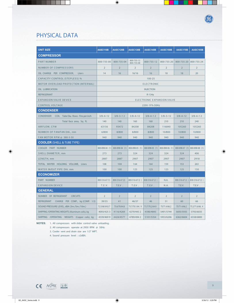
UNIT SIZE AASC110B AASC120B AASC130B AASC140B AASC150B AASC170B AASC185B
COMPRESSOR
42-537-00802-537-00802-537-008 21-537-00840-537-008 00-537-008REBMUN TRAP
2222222SROSSERPMOC FO REBMUN
OIL CHARGE PER COMPRESSOR, Liters 14 16 16/16 16 18 18 20
52-001% )SSELPETS( LORTNOC YTICAPAC
CINORTCELE)LANRETNI( NOITCETORP DAOLREVO ROTOM
OIL LUBRICATION INJECTION
REFRIGERANT R-134a
EVLAV NOISNAPXE CINORTCELEECIVED EVLAV NOISNAPXE
zH05-hP1-V022 EGATLOV LORTNOC
CONDENSERCONDENSER COIL Tube Dia.- Rows - Fins per inch 3/8–4–12 3/8–3–1 2 3/8–4–12 3/8–4–1 2 3/8–3–12 3/8–4–12 3/8–4–1 2
Total face area, Sq. ft. 140 140 160 160 210 210 240
06250106250104861180248802482743965136MFC ,WOLFRIA
008/01008/01008/01008/8008/8008/8008/6mm ,.AID NAF/NAF FO REBMUN
04904904904904904904905-3-083 @ MPR ROTOM NAF
COOLER (SHELL & TUBE TYPE)
COOLER PART NUMBER 800-898-04 (1) 800-898-04 (1) 800-898-05 (1) 800-898-05 (1) 800-898-06 (1) 800-898-07 (1) 800-898-08 (1)
604423423423423372372mm ,RETEMAID LLEHS
8192709270927092709278827882mm ,HTGNEL
TOTAL WATER HOLDING VOLUME, Liters 108 108 164 164 159 153 263
051521521521521001001mm .AID EPIP TUO/NI RETAW
ECONOMIZERPART NUMBER 800-516-67 (1) 800-516-67 (2) 800-516-67 (2 ) 800-516-67 (2 ) N.A. 800-516-67 (2 ) 800-516-67 (2 )
.V.E.TECIVED NOISNAPXE T.E.V . T .E.V . T .E.V . N .A. T.E.V. T.E.V .
GENERALNUMBER OF REFRIGERANT CIRCUITS 2 2 2 2 2 2 2
REFRIGERANT CHARGE PER COMP., kg (COMP. 1/2) 39/35 41 46/37 46 51 60 66
SOUND PRESSURE LEVEL, dBA (3m./5m./10m.) 72.5/68.9/63.7 73.6/70/64.8 73.7/70.1/64. 9 73.7/70.2/64.9 75/71.4/66.2 75/71.4/66.2 75.2/71.6/66. 4
SHIPPING /OPERATING WEIGHTS (Aluminum coils), kg 4093/425 3 4116/4269 4279/443 2 4590/4843 5491/5744 5693/5935 5793/6035
SHIPPING /OPERATING WEIGHTS (Copper coils), kg 4539/469 9 4424/4577 4789/494 2 5101/5354 5953/6206 6362/6604 6558/6800
NOTES: 1. All compressors with slider control valve unloading.
2. All compressors operate at 2950 RPM @ 50Hz.
3. Cooler vent and drain size are 1/2" MPT.
4. Sound pressure level : ±2dBA.
800-735-12 800-735-08
GE_AASC_Series.indd 9 3/26/12 5:20 PM

10
PHYSICAL DATA
NOTES: 1. All compressors with slider control valve unloading.
2. All compressors operate at 2950 RPM @ 50Hz.
3. Cooler vent and drain size are 1/2" MPT.
4. Sound pressure level : ±2dBA.
UNIT SIZE AASC200B AASC215B AASC240B AASC255B AASC275B AASC300B
COMPRESSOR
23-537-00882-537-008 42-537-00802-537-008 23-537-008 82-537-008REBMUN TRAP
333322SROSSERPMOC FO REBMUN
OIL CHARGE PER COMPRESSOR, Liters 23 23 18 20 23 23
CAPACITY CONTROL (STEPLESS) % 61-001 52-001
CINORTCELE)LANRETNI( NOITCETORP DAOLREVO ROTOM
OIL LUBRICATION INJECTION
REFRIGERANT R-134a
EVLAV NOISNAPXE CINORTCELEECIVED EVLAV NOISNAPXE
CONTROL VOLTAGE 220V-1Ph-50Hz
CONDENSERCONDENSER COIL Tube Dia.- Rows - Fins per inch 3/8–4–12 3/8–4–12 3/8–3–12 3/8–3–12 3/8–4–12 3/8–4–12
Total face area, Sq. ft. 2 40 276 315 315 360 360
864981846981213012213012213621213621MFC ,WOLFRIA
008/81008/81008/81008/81008/21008/21mm ,.AID NAF/NAF FO REBMUN
04904904904904904905-3-083 @ MPR ROTOM NAF
COOLER (SHELL & TUBE TYPE)
COOLER PART NUMBER 800-898-20 (1) 800-898-20 (1) 800-898-09 (1) 800-898-09 (1) 800-898-10 (1) 800-898-11 (1)
805805604604604604mm ,RETEMAID LLEHS
539253928192819281928192mm ,HTGNEL
TOTAL WATER HOLDING VOLUME, Liters 256 256 242 242 419 419
002002051051051051mm .AID EPIP TUO/NI RETAW
ECONOMIZERPART NUMBER 800-516-67 (2) 800-516-67 (2) N.A. N.A. N.A. N.A.
.A.N.A.N.A.N.A.N.V.E.T.V.E.TECIVED NOISNAPXE
GENERALNUMBER OF REFRIGERANT CIRCUITS 2 2 3 3 3 3
REFRIGERANT CHARGE PER COMP., kg (COMP. 1/2) 70 75 51 59 64 68
SOUND PRESSURE LEVEL, dBA (3m./5m./10m.) 76/72.5/67.2 76.1/72.6/67.3 77.4/73.9/68.7 77.6/74.1/68.8 77.8/74.3/69 77.9/74.4/69.1
SHIPPING /OPERATING WEIGHTS (Aluminum coils), kg 6092/633 4 6262/6504 8698/9117 8635/905 4 9279/9698 9329/9748
SHIPPING /OPERATING WEIGHTS (Copper coils), kg 6587/709 9 7142/7384 9391/9810 9328/9747 10427/10846 10478/1089 7
GE_AASC_Series.indd 10 3/26/12 5:20 PM
11
PHYSICAL DATA
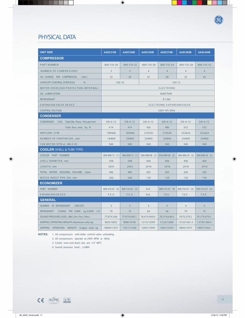
UNIT SIZE AASC315B AASC330B AASC350B AASC370B AASC405B AASC445B
COMPRESSOR
23-537-00882-537-008 42-537-00882-537-008 23-537-008 82-537-008REBMUN TRAP
444433SROSSERPMOC FO REBMUN
OIL CHARGE PER COMPRESSOR, Liters 23 23 23 20 23 23
CAPACITY CONTROL (STEPLESS) % 21-001 61-001
CINORTCELE)LANRETNI( NOITCETORP DAOLREVO ROTOM
OIL LUBRICATION INJECTION
REFRIGERANT R-134a
EVLAV NOISNAPXE CINORTCELEECIVED EVLAV NOISNAPXE
CONTROL VOLTAGE 220V-1Ph-50Hz
CONDENSERCONDENSER COIL Tube Dia.- Rows - Fins per inch 3/8–4–12 3/8–4–12 3/8–4–12 3/8–4–12 3/8–4–12 3/8–4–12
Total face area, Sq. ft. 4 14 414 420 480 552 552
426252426252025012025012864981864981MFC ,WOLFRIA
008/42008/42008/02008/02008/81008/81mm ,.AID NAF/NAF FO REBMUN
04904904904904904905-3-083 @ MPR ROTOM NAF
COOLER (SHELL & TUBE TYPE)
COOLER PART NUMBER 800-898-12 (1) 800-898-12 (1) 800-898-08 (2) 800-898-08 (2) 800-898-20 (2) 800-898-20 (2)
604604604604805805mm ,RETEMAID LLEHS
819281928192819253925392mm ,HTGNEL
TOTAL WATER HOLDING VOLUME, Liters 406 406 263 263 256 256
051051051051002002mm .AID EPIP TUO/NI RETAW
ECONOMIZERPART NUMBER 800-516-67 (3) 800-516-67 (3) N.A. 800-516-67 (4) 800-516-67 (4) 800-516-67 (4)
.V.E.T.V.E.TECIVED NOISNAPXE N.A. T.E.V. T.E.V . T .E.V.
GENERALNUMBER OF REFRIGERANT CIRCUITS 3 3 4 4 4 4
REFRIGERANT CHARGE PER COMP., kg (COMP. 1/2) 70 75 64 66 70 75
SOUND PRESSURE LEVEL, dBA (3m./5m./10m.) 77.8/74.3/69 77.9/74.4/69.1 78.4/74.9/69.9 78.2/74.6/69.4 79/75.5/70.2 79.1/75.6/70.3
SHIPPING /OPERATING WEIGHTS (Aluminum coils), kg 9633/10052 9690/10109 12115/12599 12125/12609 13132/1361 6 13176/1366 0
SHIPPING /OPERATING WEIGHTS (Copper coils), kg 10954/11373 11011/11430 13455/13939 13657/14141 14893/15377 14937/15421
NOTES: 1. All compressors with slider control valve unloading.
2. All compressors operate at 2950 RPM @ 50Hz.
3. Cooler vent and drain size are 1/2" MPT.
4. Sound pressure level : ±2dBA.
GE_AASC_Series.indd 11 3/26/12 5:20 PM

12
SELECTION PROCEDURE (ENGLISH UNITS)
TABLE - 2
EVAPORATOR FOULINGFACTOR (HR-FT2-0F/BTU)
0.0001 00.0002 50.0005 00.0007 50.0010 0
CAPACITYCORRECTION
FACTOR1.00 00.99 20.97 80.96 50.95 1
POWERINPUT
FACTOR1.00 00.99 70.99 00.98 40.97 8
ARISTANDARDS
ARI-550/590-98ARI-590-86ARI-590-81
TABLE - 3CHILLED WATER TEMPERATURE RISE (0F)
CO
RR
ECTI
ON
FA
CTO
R (
0 F)
0
-0.2
-0.45 10
+0.4
+0.2
+0.6
15 20
ELEVATION ABOVESEA LEVEL (FT.)
CAPACITYCORRECTION
FACTOR0
200 0400 0600 0800 0
1000 0
1.000.990.980.970.960.95
TABLE - 1
DESIGN REQUIREMENTS
The following design requirements must be known to select a package chiller.
1. Required cooling capacity in tons 2. Leaving chilled water temperature in °F (LCWT) 3. Chilled water fl ow rate in GPM4. Chilled water cooling range in °F (water in temp. - water out temp.) 5. Design ambient temperature 6. Minimum ambient temperature 7. Altitude8. Electrical power supply
SAMPLE SELECTION
Select an Air Cooled Packaged chiller for the following conditions: Required system capacity is 110 tons at 54°F entering chilled water and 44°F leaving water. Design ambient temperature is 95°F. Altitude is 2000 feet above sea level. Water cooler fouling factor is 0.00010. Power supply: 380/415V-3Ph-50Hz.
STEP-1: UNIT SELECTION
Entering the capacity performance data at given LCWT and ambient temperature.AASC120B chiller unit at sea level will produce 115.7 tons and 123 kW compressor power input at 44°F leaving chilled water temperature with 10°F water temperature diff erence and 95°F ambient temperature.
For the conditions required, the unit actual cooling capacity when corrected for altitude(0.99) and fouling factor (1.0). Capacity = 115.7x0.99x1.0 = 114.5 Tons, which then exceedsthe requirements. So the selection is correct.
STEP-2: CHILLED WATER FLOW (GPM):
Water GPM = Required capacity (Tons) x 24 = 110 x 24 = 264 GPM Cooling Range, ΔT 10°F
Referring to pressure drop chart (page # 22), pressure drop 264 GPM = 13.3 ffl of water for selected model.
NOTE: The total fl ow rate should be divided by 2 for models AASC350B - AASC445B to fi nd out the total pressure drop.
STEP-3: ELECTRICAL
Refer to electrical data at 380/415V-3Ph-50Hz, the main power wire size for AASC120B is to be sized for a minimum circuit ampacity (MCA) of 269 Amps and maximum over current protection (MOCP) of 374 Amps.
STEP-4: CHILLED WATER PUMP SELECTION
For chilled water pump selection, add all pressure drop in the closed chilled water loop piping to the pressure drop calculated in step 2.
STEP-5: LCWT CORRECTION
Refer to table-3: Add correction factor to design leaving chilled water temperature (LCWT) when chilled water temperature range is above 10°F and subtract correction from design leaving chilled water temperature (LCWT) when water temperature range is below 10°F.
EXAMPLE: If LCWT rise is 12.5°F, enter correction curve at 12.5°F and read the correction factor of 0.2. The corrected LCWT is 44+0.2 = 44.2°F.
NOTE: 1. When the chilled water temperature rise is less than 5°F, the high water fl ow rate will result to excessive pressure drop. In such cases, contact factory for special selection of a cooler with wider baffl e spacing. 2. Please refer to water pressure drop curves.
GE_AASC_Series.indd 12 3/26/12 5:20 PM

13
SELECTION PROCEDURE (METRIC UNITS)
TABLE - 2
EVAPORATOR FOULINGFACTOR (M2-0C/W)
0.0000180.0000440.0000880.0001320.000176
CAPACITYCORRECTION
FACTOR1.00 00.99 20.97 80.96 50.95 1
POWERINPUT
FACTOR1.00 00.99 70.99 00.98 40.97 8
ARISTANDARDS
ARI-550/590-98ARI-590-86ARI-590-81
TABLE - 3CHILLED WATER TEMPERATURE RISE (0C)
CO
RR
ECTI
ON
FA
CTO
R (0
C)
+0.33
+0.22
+0.11
-0.11
-0.2254 6 7 8
0
109
ELEVATION ABOVESEA LEVEL (Meter)
CAPACITYCORRECTION
FACTOR0
600120 0180 0240 0300 0
1.000.990.980.970.960.95
TABLE - 1
DESIGN REQUIREMENTS
The following design requirements must be known to select a proper package chiller.
1. Required cooling capacity in kilowatt (kW) 2. Leaving chilled water temperature in °C (LCWT) 3. Chilled water fl ow rate in LPS4. Chilled water cooling range in °C (water in temp. - water out temp.) 5. Design ambient temperature 6. Minimum ambient temperature 7. Altitude8. Electrical power supply
SAMPLE SELECTION
Select an Air Cooled Packaged chiller for the following conditions: Required system capacity is 395 kW at 12°C entering chilled water and 6°C leaving water. Design ambient temperature is 35°C. Altitude is 600 meter abovesea level. Water cooler fouling factor is 0.000018. Power supply: 380/415V-3Ph-50Hz.
STEP-1: UNIT SELECTION
Entering the capacity performance data at given LCWT and ambient temperature. AASC120B chiller unit at sea level will produce 405.1 kW and 122.8 kW compressor power input at 6°C leaving chilled water temperature with 6°C water temperature diff erence and 35°C ambient temperature.
For the conditions required, the unit actual cooling capacity when corrected for altitude (0.99) and fouling factor (1.0). Capacity = 405.1x0.99X1.0 = 401 kW,which then exceeds the requirements. So the selection is correct.
STEP-2: CHILLED WATER FLOW (LPS):
Water LPS = Required capacity (kW) x 0.239 = 395 x 0.239 = 15.7 LPS Cooling Range, ΔT 6°C
Referring to pressure drop chart (page # 22), pressure drop at 15.7 LPS = 36 kPa for selected model.
NOTE: The total fl ow rate should be divided by 2 for models AASC350B - AASC445B to fi nd out the total pressure drop.
STEP-3: ELECTRICAL
Refer to electrical data at 380/415V-3Ph-50Hz, the main power wire size for AASC120B is to be sized for a minimum circuit ampacity (MCA) of 269 Amps and maximum over current protection (MOCP) of 374 Amps.
STEP-4: CHILLED WATER PUMP SELECTION
For chilled water pump selection, add all pressure drop in the closed chilled water loop piping to the pressure drop calculated in step 2.
STEP-5: LCWT CORRECTION
Refer to table-3: Add correction factor to design leaving chilled water temperature (LCWT) when chilled water temperature range is above 6°C and subtract correction from design leaving chilled water temperature (LCWT) when water temperature range is below 6°C.
EXAMPLE: If LCWT rise is 7.4°C, enter correction curve at 7.4°C and read the correction factor of 0.11. The corrected LCWT is 6°C+0.11 = 6.11°C.
NOTE: 1. When the chilled water temperature rise is less than 3°C, the high water fl ow rate will result to excessive pressure drop. In such cases, contact factory for special selection of a cooler with wider baffl e spacing. 2. Please refer to water pressure drop curves.
GE_AASC_Series.indd 13 3/26/12 5:20 PM
14
ETHYLENE GLYCOL SOLUTION CAPACITY CORRECTION (ANTIFREEZE)
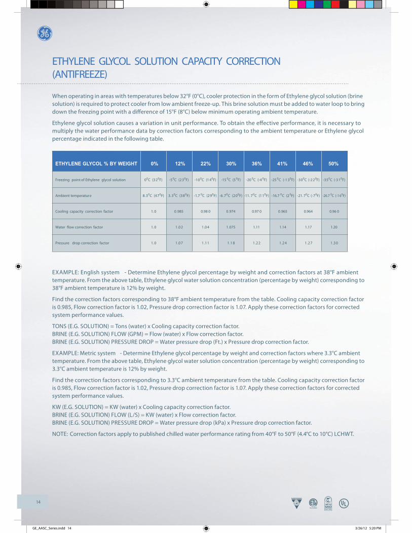
When operating in areas with temperatures below 32°F (0°C), cooler protection in the form of Ethylene glycol solution (brine solution) is required to protect cooler from low ambient freeze-up. This brine solution must be added to water loop to bring down the freezing point with a diff erence of 15°F (8°C) below minimum operating ambient temperature.
Ethylene glycol solution causes a variation in unit performance. To obtain the eff ective performance, it is necessary to multiply the water performance data by correction factors corresponding to the ambient temperature or Ethylene glycol percentage indicated in the following table.
EXAMPLE: English system - Determine Ethylene glycol percentage by weight and correction factors at 38°F ambient temperature. From the above table, Ethylene glycol water solution concentration (percentage by weight) corresponding to 38°F ambient temperature is 12% by weight.
Find the correction factors corresponding to 38°F ambient temperature from the table. Cooling capacity correction factor is 0.985, Flow correction factor is 1.02, Pressure drop correction factor is 1.07. Apply these correction factors for corrected system performance values.
TONS (E.G. SOLUTION) = Tons (water) x Cooling capacity correction factor. BRINE (E.G. SOLUTION) FLOW (GPM) = Flow (water) x Flow correction factor. BRINE (E.G. SOLUTION) PRESSURE DROP = Water pressure drop (Ft.) x Pressure drop correction factor.
EXAMPLE: Metric system - Determine Ethylene glycol percentage by weight and correction factors where 3.3°C ambient temperature. From the above table, Ethylene glycol water solution concentration (percentage by weight) corresponding to 3.3°C ambient temperature is 12% by weight.
Find the correction factors corresponding to 3.3°C ambient temperature from the table. Cooling capacity correction factor is 0.985, Flow correction factor is 1.02, Pressure drop correction factor is 1.07. Apply these correction factors for corrected system performance values.
KW (E.G. SOLUTION) = KW (water) x Cooling capacity correction factor. BRINE (E.G. SOLUTION) FLOW (L/S) = KW (water) x Flow correction factor. BRINE (E.G. SOLUTION) PRESSURE DROP = Water pressure drop (kPa) x Pressure drop correction factor.
NOTE: Correction factors apply to published chilled water performance rating from 40°F to 50°F (4.4°C to 10°C) LCHWT.
ETHYLENE GLYCOL % BY WEIGHT 0% 12% 22% 30% 36% 41% 46% 50%
Freezing point of Ethylene glycol solution 00C (320F) -50C (230F) -100C (140F) -15 0C (50F) -20 0C (-4 0F) -25 0C (-1 30F) -300C (-2 20F) -350C (-3 10F)
Ambient temperature 8. 30C (470F) 3. 30C (380F) -1.7 0C (290F) -6. 70C (200F) -11. 70C (110F) -16.7 0C (20F) -21. 70C (-70F) -26.7 0C (-1 60F)
Cooling capacity correction factor 1. 0 0.985 0.98 0 0.974 0.97 0 0.965 0.964 0.96 0
Water flow correction factor 1. 0 1.0 2 1.0 4 1.075 1.11 1.14 1.17 1.20
Pressure drop correction factor 1. 0 1.0 7 1.1 1 1.1 8 1.2 2 1.2 4 1.2 7 1.3 0
GE_AASC_Series.indd 14 3/26/12 5:20 PM
15
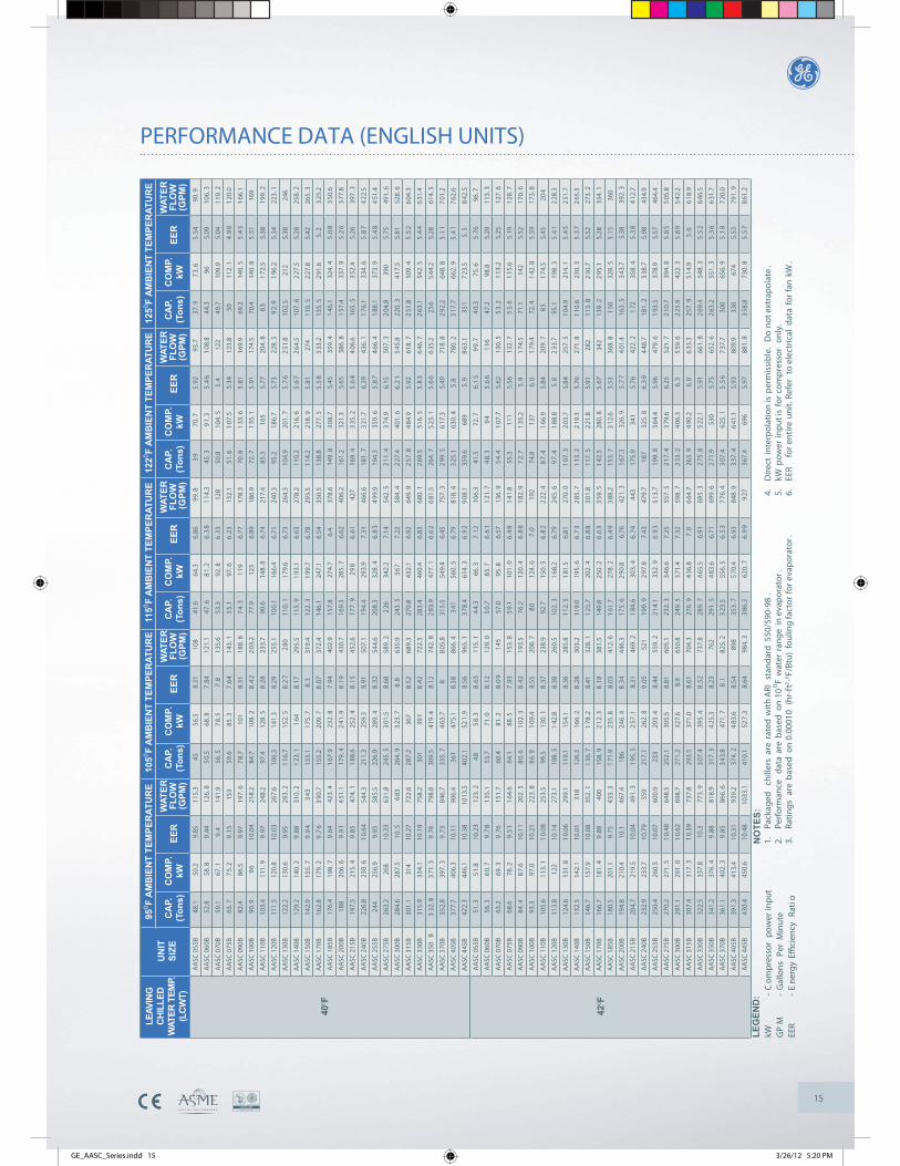
PERFORMANCE DATA (ENGLISH UNITS)
AA
SC 0
55B
48.1
50.2
9.85
115.
345
56.5
8.31
108
41.6
64.3
6.86
99.8
39
70.7
5.9
293
.737
.97
3.6
5.5
490
.9
AA
SC 0
60B
52.8
58.8
9.4
412
6.8
50.
568
.87
.84
121.
147
.68
1.2
6.3
81
14.3
45.3
91.
35
.46
108
.844
.396
5.09
106.
3
AA
SC 0
70B
59.1
67.1
9.4
141.
956
.57
8.5
7.8
135.
653
.392
.86
.33
128
50.8
104.
55
.412
249
.710
9.9
5.04
119.
2
AA
SC 0
75B
63.7
75.
29
.15
153
59.6
85.3
7.6
414
3.1
55.
197
.66
.23
132.
151
.61
07.5
5.34
123.
850
112.
14
.98
120
.0
AA
SC 0
90B
82.4
86.5
9.97
197.
67
8.7
101
8.31
188.
87
4.3
119
6.77
178.
370
.81
33.6
5.8
116
9.9
69.2
140.
55
.43
166
.1
AA
SC 1
00B
90.9
96
10.0
421
8.2
84.7
108.
28
.42
203
.277
.912
36.
8918
6.9
72.7
135
.15
.91
174.
570
.414
0.8
5.5
116
9
AA
SC 1
10B
103.
411
1.9
9.9
724
8.2
97.4
128.
58
.28
233.
790
.614
8.8
6.74
217.
485
.316
55.
7720
4.8
83
172
.55.
3819
9.2
AA
SC 1
20B
111.
512
0.8
10.0
326
7.6
106.
314
1.3
8.29
255.
110
0.1
166.
46.
7124
0.3
95.2
186.
75.
7322
8.5
92.
91
96.2
5.34
223.
1
AA
SC 1
30B
122.
213
0.6
9.95
293.
21
16.7
152.
58
.27
280
110.
117
9.6
6.73
264.
310
4.9
201.
75
.76
251
.810
2.5
212
5.38
246
AA
SC 1
40B
129.
214
0.2
9.8
831
0.2
123
.11
648.
1729
5.5
115.
91
93.1
6.63
278.
211
0.2
216.
65
.67
264
.510
7.6
227
.55.
2825
8.2
AA
SC 1
50B
142.
915
5.7
9.9
43
4313
3.1
175.
78
.331
9.4
122.
31
99.7
6.78
293.
511
4.2
218.
95
.81
274
110.
52
27.8
5.42
265.
3
AA
SC 1
70B
162.
817
9.2
9.7
63
90.7
155.
220
9.7
8.0
737
2.4
146.
124
7.1
6.54
350.
513
8.8
277.
55
.58
333
.213
5.5
291
.65.
23
25.2
AA
SC 1
85B
176.
419
8.7
9.6
442
3.4
167
.923
2.8
7.9
440
2.9
157.
827
4.7
6.4
378.
614
9.8
308
.75.
4535
9.4
146
.132
4.4
5.0
83
50.6
AA
SC 2
00B
188
206.
69
.91
451
.117
9.4
241
.98
.19
430.
716
9.3
285.
76.
6240
6.2
161.
232
1.3
5.65
386.
81
57.4
337.
95
.26
377
.8
AA
SC 2
15B
197.
521
5.4
9.8
547
4.1
188
.625
2.4
8.1
545
2.6
177.
92
98
6.6
142
716
9.4
335
.25
.64
406
.616
5.5
352
.45.
2639
7.3
AA
SC 2
40B
226.
823
0.6
10.
6454
4.3
211.
325
9.3
8.91
507.
119
4.4
293.
97.
3146
6.6
181.
73
21.7
6.29
436.
11
76.1
334.
65
.87
422
.5
AA
SC 2
55B
244
256.
99.
9358
5.5
226.
928
9.4
8.3
254
4.6
208.
332
8.4
6.8
34
99.9
194.
335
9.6
5.8
74
66.4
188
. 137
3.9
5.4
84
51.4
AA
SC 2
75B
263.
226
810
.33
631.
824
5.5
301
.58.
6858
9.2
226
342.
27.
1454
2.5
211
.43
74.9
6.15
507.
32
04.8
390
5.75
491.
6
AA
SC 3
00B
284.
628
7.5
10.5
683
264.
93
23.7
8.8
635.
924
3.5
367
7.22
584.
42
27.4
401.
66
.21
545
.822
0.3
417
.55.
8152
8.6
AA
SC 3
15B
301.
131
410
.27
722.
628
7.2
367
8.52
689.
327
0.8
432.
16.
9264
9.9
257
.84
84.9
5.92
618.
72
51.8
509.
45
.52
604
.3
AA
SC 3
30B
315.
933
4.1
10.1
975
8.2
301
391
8.4
272
2.3
283.
446
0.4
6.83
680.
12
69.5
516.
55
.83
646
.72
63.1
542.
55
.44
631
.4
AA
SC 3
50B
332
.83
71.3
9.7
679
8.8
309.
541
9.4
8.12
742.
82
83.9
477.
16
.62
681
.526
4.7
523
.15
.66
635
.225
65
44.2
5.28
614.
5
AA
SC 3
70B
352.
839
7.3
9.7
384
6.7
335.
74
65.7
88
05.8
315.
554
9.4
6.45
757.
32
99.5
617
.35.
4971
8.8
292
.264
8.8
5.1
17
01.2
AA
SC 4
05B
377.
740
6.3
10.1
190
6.4
361
475.
18.
3886
6.4
341
560.
56.
7981
8.4
325
.163
0.4
5.8
780.
23
17.7
662.
95
.41
762
.6
AA
SC 4
45B
422.
344
6.1
10.3
810
13.5
402.
152
1.9
8.56
965.
13
78.4
614.
36
.92
908
.135
9.6
689
5.9
863
.135
17
23.5
5.5
842
.5
AA
SC 0
55B
51.3
51.
810
.23
123.
24
85
8.3
8.6
311
5.1
44.
366
.37
.12
106.
341
.572
.76
.15
99.
74
0.3
75.6
5.7
696
.7
AA
SC 0
60B
56.3
60.
79
.78
135
.153
.771
.08
.12
129.
05
0.7
83.7
6.6
11
21.7
48.
39
45
.66
116
47.2
98.8
5.29
113.
3
AA
SC 0
70B
63.2
69.3
9.7
615
1.7
60.4
81.2
8.0
91
4557
.095
.86.
5713
6.9
54.
41
07.7
5.62
130.
55
3.2
113
.25.
2512
7.6
AA
SC 0
75B
68.6
78.2
9.5
11
64.6
64.1
88.5
7.9
315
3.8
59.
110
1.0
6.4
81
41.8
55.3
111
5.56
132.
75
3.6
115
.65.
1912
8.7
AA
SC 0
90B
84.4
87.
610
.11
202.
58
0.6
102
.38
.42
193.
576
.212
0.4
6.8
81
82.9
72.
71
35.2
5.9
174
.571
.114
25.
5217
0.6
AA
SC 1
00B
93.3
97.0
10.2
122
3.8
86.
91
09.4
8.55
208.
78
012
4.6
7.0
192
74.8
137
6.0
179
.472
.41
42.8
5.5
917
3.8
AA
SC 1
10B
105.
611
3.1
10.
0825
3.5
99.5
130.
18
.37
238.
992
.715
0.5
6.8
22
22.4
87.
41
66.9
5.84
209.
78
51
74.5
5.45
204
AA
SC 1
20B
113.
812
210
.14
273.
110
8.5
142
.88.
3826
0.5
102.
31
68.2
6.79
245.
69
7.4
188
.85.
82
33.7
95.1
198.
35
.41
228
.3
AA
SC 1
30B
124.
613
1 .8
10.
0629
9.1
119.
115
4.1
8.36
285.
811
2.5
181
.56.
8127
0.0
107
.32
03.7
5.84
257.
51
04.9
214.
15
.45
251
.7
AA
SC 1
40B
132.
514
2.1
10.0
131
812
6.3
166.
28
.28
303.
211
9.0
195.
66
.73
285
.71
13.2
219
.35.
7627
1.8
110
.623
0.3
5.3
72
65.5
AA
SC 1
50B
146.
715
7.9
10.0
835
2.1
136
.71
78.2
8.41
328.
11
25.7
202.
46
.88
301
.811
7.5
221
.85.
9128
211
3.8
230
.75.
5227
3.2
AA
SC 1
70B
166.
718
1.4
9.8
840
015
8.9
212
.38
.18
381.
514
9.8
250.
26
.63
359
.51
42.5
280.
85
.67
342
139.
22
95.1
5.28
334.
1
AA
SC 1
85B
180.
520
1.1
9.75
433.
31
71.9
235
.88.
0341
2.6
161
.727
8.2
6.4
93
88.2
153.
73
12.6
5.53
368.
81
5032
8.5
5.1
536
0
AA
SC 2
00B
194.
821
0.4
10.1
467.
418
624
6.4
8.3
444
6.3
175.
62
90.8
6.76
421.
31
67.3
326.
95
.77
401
.416
3.5
343
.75.
3839
2.3
AA
SC 2
15B
204.
721
9.5
10.0
449
1.3
195
.52
57.1
8.31
469.
21
84.6
303.
46
.74
443
175.
934
15.
7642
2.2
172
358.
45
.38
412
.7
AA
SC 2
40B
232.
923
3.7
10.7
955
921
7.1
262.
89
.05
521
199.
92
97.8
7.43
479.
718
732
5.8
6.3
94
48.7
181.
23
38.7
5.98
434.
9
AA
SC 2
55B
250.
426
0.5
10.0
760
0.9
233
293
.48.
4455
9.2
214
.133
2.9
6.9
35
13.7
199.
83
64.4
5.96
479.
61
93.5
378.
95.
5746
4.4
AA
SC 2
75B
270.
227
1.5
10.
4864
8.5
252.
130
5.5
8.81
605.
123
2.3
346
.67.
2555
7.5
217
.43
79.6
6.25
521.
72
10.7
394.
85
.85
505
.8
AA
SC 3
00B
291.
129
1.0
10.
6269
8.7
271.
232
7.6
8.9
650.
824
9.5
371
.47.
3259
8.7
233
.24
06.3
6.3
559
.62
25.9
422.
35
.89
542
.2
AA
SC 3
15B
307.
431
7.3
10.
3973
7.8
293.
537
1.0
8.61
704.
327
6.9
436
.87.
06
64.7
263.
94
90.2
6.0
633
.325
7.9
514
.95.
66
18.9
AA
SC 3
30B
322.
533
7.8
10.3
773.
93
07.4
395.
48
.52
737.
828
9.7
465
.56.
9169
5.3
275
.85
22.1
5.91
661.
82
69.4
548.
35
.52
646
.5
AA
SC 3
50B
341.
237
6.4
9.8
881
8.9
317.
54
25.3
8.23
762
291.
54
83.6
6.71
699.
62
71.9
530
5.75
652.
62
63.2
551.
35
.36
631
.7
AA
SC 3
70B
361.
140
2.3
9.8
586
6.6
343
.847
1.7
8.1
825.
23
23.5
556.
56
.53
776
.43
07.4
625.
15
.56
737
.730
065
6.9
5.1
87
20.0
AA
SC 4
05B
391.
341
3.4
10.3
193
9.2
374.
24
83.6
8.54
898
353.
75
70.4
6.93
848.
93
37.4
641
.15.
9380
9.9
330
674
5.53
791.
9
AA
SC 4
45B
430.
445
0.6
10.4
810
33.1
410.
152
7.3
8.64
984.
33
86.3
620.
76
.99
927
367.
469
65.
9788
1.8
358
.873
0.8
5.5
78
61.2
LEAV
ING
CHIL
LED
WAT
ER T
EMP.
(LCW
T)
UN
ITSI
ZE
950 F
AM
BIE
NT
TEM
PER
ATU
RE
1050 F
AM
BIE
NT
TEM
PER
ATU
RE
1150 F
AM
BIE
NT
TEM
PER
ATU
RE
1220 F
AM
BIE
NT
TEM
PER
ATU
RE
1250 F
AM
BIE
NT
TEM
PER
ATU
RE
CA
P.(T
ons)
LEG
END
:kW
-C
ompr
esso
r po
wer
inpu
tG
PM
-G
allo
ns P
er M
inut
eEE
R-
Ene
rgy
Effici
ency
Rat
io
400 F
420 F
CO
MP.
kWEE
RW
ATER
FLO
W(G
PM)
CA
P.(T
ons)
CO
MP.
kWEE
RW
ATER
FLO
W(G
PM)
CA
P.(T
ons)
CO
MP.
kWEE
RW
ATER
FLO
W (G
PM)
CA
P.(T
ons)
CO
MP.
kWEE
RW
ATER
FLO
W(G
PM)
CA
P.(T
ons)
CO
MP.
kWW
ATER
FLO
W(G
PM)
EER
NO
TES:
1.Pa
ckag
ed
chill
ers
are
rate
d w
ith A
RI s
tand
ard
550/
590-
98.
2.Pe
rfor
man
ce
data
are
bas
ed o
n 10
0 F w
ater
ran
ge i
n ev
apor
ator
.3.
Ratin
gs a
re b
ased
on
0.00
010
(hr-
ft2 -0 F/
Btu)
fou
ling
fact
or f
or e
vapo
rato
r.
4.D
irect
inte
rpol
atio
n is
per
mis
sibl
e. D
o no
t ext
rapo
late
.5.
kW p
ower
inpu
t is
for c
ompr
esso
r on
ly.
6.EE
R fo
r ent
ire u
nit.
Refe
r to
ele
ctric
al d
ata
for f
an k
W.
GE_AASC_Series.indd 15 3/26/12 5:20 PM
16
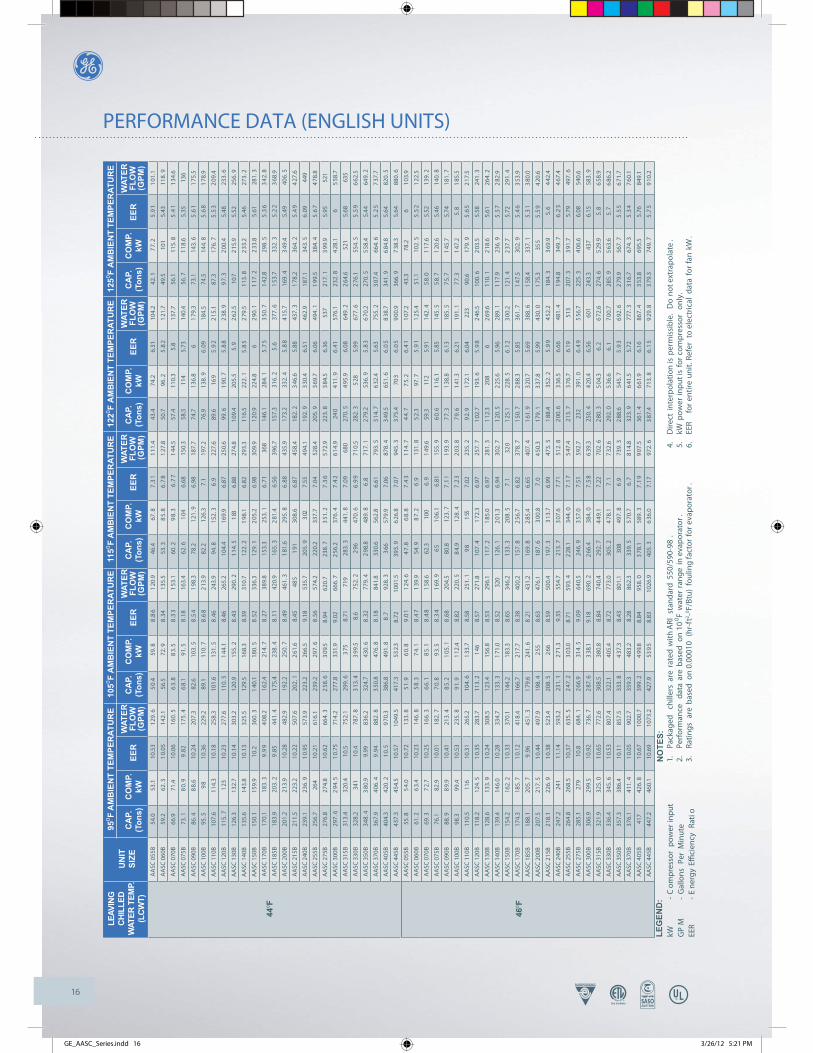
PERFORMANCE DATA (ENGLISH UNITS)
LEG
END
:kW
-C
ompr
esso
r po
wer
inpu
tG
PM
-G
allo
ns P
er M
inut
eEE
R-
Ene
rgy
Effici
ency
Rat
io
440 F
460 F
NO
TES:
1.Pa
ckag
ed
chill
ers
are
rate
d w
ith A
RI s
tand
ard
550/
590-
98.
2.Pe
rfor
man
ce
data
are
bas
ed o
n 10
0 F w
ater
ran
ge i
n ev
apor
ator
.3.
Ratin
gs a
re b
ased
on
0.00
010
(hr-
ft2 -0 F/
Btu)
fou
ling
fact
or f
or e
vapo
rato
r.
4.D
irect
inte
rpol
atio
n is
per
mis
sibl
e. D
o no
t ext
rapo
late
.5.
kW p
ower
inpu
t is
for c
ompr
esso
r on
ly.
6.EE
R fo
r ent
ire u
nit.
Refe
r to
ele
ctric
al d
ata
for f
an k
W.
AA
SC 0
55B
54.0
53.1
10.5
312
9.6
50.
459
.88
.86
120
.946
.467
.87
.31
111
.443
.474
.26.
3110
4.2
42.1
77.
25
.91
101
.1
AA
SC 0
60B
59.2
62.3
10.
0514
2.1
56.5
72.9
8.3
413
5.5
53.3
85.
86
.78
127
.850
.796
.25
.82
121
.749
.510
15.
4311
8.9
AA
SC 0
70B
66.9
71.4
10.0
616
0.5
63.
88
3.5
8.3
31
53.1
60.2
98.
36
.77
144
.557
.411
0.3
5.8
137.
756
.111
5.8
5.4
11
34.6
AA
SC 0
75B
73.1
80.
99
.82
175.
46
8.1
91.5
8.1
816
3.4
62.6
104
6.68
150.
358
.51 1
45.
7314
0.4
56.7
118
.65.
3513
6
AA
SC 0
90B
86.4
88.
610
.24
207.
382
.610
3.5
8.5
41
98.3
78.2
121.
96.
9818
7.7
74.7
136.
86
179
.373
.114
3.6
5.6
11
75.5
AA
SC 1
00B
95.5
98
10.3
622
9.2
89.1
110.
78
.68
213
.982
.212
6.3
7.1
197.
276
.913
8.9
6.0
918
4.5
74.5
144.
85
.68
178
.9
AA
SC 1
10B
107.
611
4.3
10.1
825
8.3
101.
613
1.5
8.4
624
3.9
94.8
152.
36
.922
7.6
89.6
169
5.9
22
15.1
87.3
176.
75
.53
209
.4
AA
SC 1
20B
115.
71
2310
.23
277.
611
0.5
144
.18.
4626
5.2
104.
416
9.9
6.87
250.
699
.61
90.7
5.8
82
38.9
97.
32
00.4
5.48
233.
6
AA
SC 1
30B
126.
313
2.7
10.1
430
3.2
120.
915
5.2
8.4
329
0.2
114
.51
836.
8827
4.8
109.
420
5.5
5.9
262
.510
72
15.9
5.52
256.
9
AA
SC 1
40B
135.
614
3.8
10.1
332
5.5
129.
516
8.3
8.39
310.
712
2.2
198
.16.
8229
3.3
116.
522
2.1
5.8
52
79.5
113.
82
33.2
5.46
273.
2
AA
SC 1
50B
150.
115
9.9
10.2
360.
31
40.1
180.
58
.52
336.
312
9.1
205
.26.
9830
9.9
120.
922
4.8
62
90.1
117
. 22
33.8
5.61
281.
3
AA
SC 1
70B
170.
118
3.3
9.9
94
08.2
162.
421
4.7
8.2
738
9.8
153.
325
3.1
6.7
136
814
6.1
284.
15
.75
350
.71
42.8
298.
55
.36
342
.8
AA
SC 1
85B
183.
920
3.2
9.8
544
1.4
175
.423
8.4
8.1
142
0.9
165.
32
81.4
6.56
396.
715
7.3
316.
25
.637
7.6
153
.733
2.3
5.2
23
68.9
AA
SC 2
00B
201.
221
3.9
10.2
848
2.9
192.
225
0.7
8.4
946
1.3
181
.629
5.8
6.8
843
5.9
173.
233
2.4
5.8
84
15.7
169.
43
49.4
5.49
406.
5
AA
SC 2
15B
211.
522
3.2
10.2
250
7.6
202.
12
61.6
8.45
485
191
308.
66.
8745
8.4
182.
23
46.6
5.88
437.
31
78.2
364.
25
.49
427
.6
AA
SC 2
40B
239.
123
6.9
10.
9557
3.9
223.
226
6.5
9.18
535.
720
5.9
302
7.55
494.
119
2.9
330
.46.
5146
2.9
187.
134
3.5
6.0
944
9
AA
SC 2
55B
256.
726
410
.21
616.
123
9.2
297.
68
.56
574.
222
0.2
337.
77.
0452
8.4
205.
93
69.7
6.06
494.
11
99.5
384.
45
.67
478
.8
AA
SC 2
75B
276.
827
4.8
10.6
266
4.3
258
.63
09.5
8.94
620.
723
8.7
351
.27
.36
572
.922
3.8
384
.56.
3653
721
7.1
399
.95.
9552
1
AA
SC 3
00B
297.
62
94.5
10.
7571
4.2
277.
833
1.9
9.02
666.
72
56.2
376.
47
.42
614
.924
04
11.9
6.4
157
6.1
232.
84
28.1
65
58.7
AA
SC 3
15B
313.
432
0.4
10.5
752.
129
9.6
375
8.71
719
283.
344
1.8
7.0
968
027
0.5
495
.96.
0864
9.2
264
.652
15.
6863
5
AA
SC 3
30B
328.
234
110
.478
7.8
313
.43
99.5
8.6
752.
22
9647
0.6
6.9
97
10.5
282.
35
285.
9967
7.6
276
.155
4.5
5.5
96
62.5
AA
SC 3
50B
348.
43
80.9
9.99
836.
232
4.7
430.
68
.32
779.
42
98.8
489.
86
.871
7.1
279
.253
6.9
5.8
36
70.2
270.
55
58.4
5.44
649.
2
AA
SC 3
70B
367.
940
6.4
9.9
488
2.8
350
.847
6.8
8.1
884
1.8
330.
656
2.8
6.61
793.
53
14.7
632
.45.
6375
5.2
307
.466
4.6
5.2
57
37.7
AA
SC 4
05B
404.
342
0.2
10.
59
70.3
386.
849
1.8
8.7
928.
33
6657
9.9
7.06
878.
43
49.5
651.
66
.05
838
.734
1.9
684
.85.
6482
0.5
AA
SC 4
45B
437.
345
4.5
10.5
710
49.5
417.
353
2.3
8.72
1001
.539
3.9
626
.87.
0794
5.3
375
.470
36
.05
900
.936
6.9
738
.35.
6488
0.6
AA
SC 0
55B
55.8
54.
010
.72
133.
85
1.9
60.
89
.01
124
.64
7.8
68.
87
.43
114
.74
4.7
75.
26
.41
107
.243
.378
.26
103
.9
AA
SC 0
60B
61.2
63.
410
.23
146.
85
8.3
74.
18
.47
139
.954
.98
7.2
6.9
131.
85
2.3
97.7
5.9
11
25.4
51.1
102.
55
.52
122
.5
AA
SC 0
70B
69.3
72.
710
.25
166.
36
6.1
85.
18
.48
158
.662
.310
06.
91
49.6
59.3
112
5.91
142.
45
8.0
117
.65.
5213
9.2
AA
SC 0
75B
76.1
82.9
10.0
118
2.7
70.
89
3.5
8.3
41
69.9
65
106
.16.
8115
5.9
60.
61
16.1
5.85
145.
55
8.7
120
.65.
4614
0.8
AA
SC 0
90B
88.9
89.
910
.41
213.
48
5.2
105
.18
.68
204.
580
.812
3.7
7.1
11
93.9
77.
31
38.8
6.13
185.
57
5.7
145
.75.
7418
1.7
AA
SC 1
00B
98.3
99.4
10.5
323
5.8
91.
91
12.4
8.82
220.
58
4.9
128.
47
.23
203
.87
9.6
141
.36.
2119
1.1
77.
31
47.2
5.8
185
.5
AA
SC 1
1 0B
110.
511
610
.31
265.
210
4.6
133
.78.
5825
1.1
98
155
7.02
235.
29
2.9
172
.16.
0422
390
.617
9.9
5.6
52
17.5
AA
SC 1
20B
118.
212
4.5
10.
3528
3.7
113.
21
468.
5727
1.8
107.
41
72.3
6.97
257.
71
02.7
193.
65
.98
246
.510
0.6
203
.55.
5824
1.3
AA
SC 1
30B
128.
613
3.9
10.
2430
8.5
123.
415
6.8
8.53
296.
111
7.2
185
.06.
9728
1.3
112
.320
86
269
.611
0.1
218
.65.
6126
4.2
AA
SC 1
40B
139.
414
6.0
10.2
833
4.7
133.
31
71.0
8.52
320
126.
12
01.3
6.94
302.
71
20.5
225
.65.
9628
9.1
117
.923
6.9
5.5
72
82.9
AA
SC 1
50B
154.
216
2.2
10.
3337
0.1
144.
218
3.3
8.65
346.
213
3.3
208.
57
.132
01
25.1
228.
56
.12
300
.212
1.4
237
.75.
7229
1.4
AA
SC 1
70B
174.
318
5.7
10.
1241
8.4
166.
721
7.7
8.38
400.
215
7.8
256
.76.
8237
8.7
150
.72
88.3
5.85
361.
71
47.5
302.
95
.46
353
.9
AA
SC 1
85B
188.
120
5.7
9.9
645
1.3
179
.624
1.6
8.2
143
1.2
169.
82
85.4
6.65
407.
41
61.9
320
.75.
6938
8.6
158
.433
7.1
5.3
13
80.0
AA
SC 2
00B
207.
521
7.5
10.
4449
7.9
198.
42
558.
6347
6.1
187.
63
00.8
7.0
450
.317
9.1
337
.85.
9943
0.0
175
.335
55
.59
420
.6
AA
SC 2
15B
218.
122
6.9
10.
3852
3.4
208.
52
668.
5950
0.4
197.
33
13.7
6.99
473.
51
88.4
352.
25
.99
452
.218
4.3
369
.95.
64
42.4
AA
SC 2
40B
247.
224
111
.14
593.
223
1.1
271
.39.
3555
4.7
213.
73
07.6
7.71
512.
82
00.6
336
.56.
6648
1.4
194
.834
9.7
6.2
34
67.4
AA
SC 2
55B
264.
826
8.5
10.3
763
5.5
247
.23
03.0
8.71
593.
42
28.1
344.
07
.17
547
.421
3.7
376
.76.
1951
320
7.3
391
.75.
7949
7.6
AA
SC 2
75B
285.
127
910
.868
4.1
266
.931
4.5
9.0
964
0.5
246.
93
57.0
7.51
592.
723
239
1.0
6.4
95
56.7
225.
34
06.6
6.08
540.
6
AA
SC 3
00B
306.
929
9.5
10.9
273
6.7
287
.63
38.1
9.18
690.
22
66.4
384.
07
.58
639
.325
0.4
420
.46.
5660
124
3.3
437
6.15
583.
9
AA
SC 3
15B
321.
932
5.0
10.
6577
2.6
308.
538
0.8
8.84
740.
429
2.7
449
.17.
2270
2.6
280
.35
04.3
6.2
672
.627
4.6
529
.95.
86
58.9
AA
SC 3
30B
336.
434
5.6
10.
5380
7.4
322.
140
5.4
8.72
773.
030
5.2
478
.17.
17
32.6
292.
05
36.6
6.1
700
.728
5.9
563
.65.
76
86.2
AA
SC 3
50B
357.
338
6.4
10.1
185
7.5
333.
84
37.3
8.43
801.
130
849
7.8
6.9
739.
32
88.6
545.
75
.93
692
.62
79.9
567.
75
.55
671
.7
AA
SC 3
70B
376.
141
1.4
10.
0590
2.7
359.
348
3.2
8.28
862.
333
9.5
570
.76.
78
14.8
323.
96
41.5
5.72
777.
33
16.7
674.
35
.34
760
.1
AA
SC 4
05B
417
426.
81
0.67
1000
.739
9.2
499
.88.
8495
8.0
378
.158
9.3
7.1
99
07.5
361.
46
61.9
6.16
867.
43
53.8
695.
55.
7684
9.1
AA
SC 4
45B
447.
246
0.1
10.6
910
73.2
427.
953
9.5
8.83
1026
.940
5.3
636
.07.
1797
2.6
387
.471
3.8
6.1
59
29.8
379
.374
9.7
5.7
59
10.2
LEAV
ING
CHIL
LED
WAT
ER T
EMP.
(LCW
T)
UN
ITSI
ZE
950 F
AM
BIE
NT
TEM
PER
ATU
RE
1050 F
AM
BIE
NT
TEM
PER
ATU
RE
1150 F
AM
BIE
NT
TEM
PER
ATU
RE
1220 F
AM
BIE
NT
TEM
PER
ATU
RE
1250 F
AM
BIE
NT
TEM
PER
ATU
RE
CA
P.(T
ons)
CO
MP.
kWEE
RW
ATER
FLO
W(G
PM)
CA
P.(T
ons)
CO
MP.
kWEE
RW
ATER
FLO
W(G
PM)
CA
P.(T
ons)
CO
MP.
kWEE
RW
ATER
FLO
W (G
PM)
CA
P.(T
ons)
CO
MP.
kWEE
RW
ATER
FLO
W(G
PM)
CA
P.(T
ons)
CO
MP.
kWW
ATER
FLO
W(G
PM)
EER
GE_AASC_Series.indd 16 3/26/12 5:21 PM

17
PERFORMANCE DATA (ENGLISH UNITS)
LEG
END
:kW
-C
ompr
esso
r po
wer
inpu
tG
PM
-G
allo
ns P
er M
inut
eEE
R-
Ene
rgy
Effici
ency
Rat
io
480 F
500 F
NO
TES:
1.Pa
ckag
ed
chill
ers
are
rate
d w
ith A
RI s
tand
ard
550/
590-
98.
2.Pe
rfor
man
ce
data
are
bas
ed o
n 10
0 F w
ater
ran
ge i
n ev
apor
ator
.3.
Ratin
gs a
re b
ased
on
0.00
010
(hr-
ft2 -0 F/
Btu)
fou
ling
fact
or f
or e
vapo
rato
r.
4.D
irect
inte
rpol
atio
n is
per
mis
sibl
e. D
o no
t ext
rapo
late
.5.
kW p
ower
inpu
t is
for c
ompr
esso
r on
ly.
6.EE
R fo
r ent
ire u
nit.
Refe
r to
ele
ctric
al d
ata
for f
an k
W.
AA
SC 0
55B
57.2
54.8
10.8
713
7.3
53.
361
.69
.13
127
.84
969
.77
.53
117.
545
.876
.16.
510
9.9
44.4
79.1
6.0
91
06.5
AA
SC 0
60B
62.7
64.2
10.
3615
0.4
59.7
75.1
8.5
814
3.3
56.3
88.
36
.98
135.
153
.698
.95
.99
128.
652
.310
3.8
5.6
125.
6
AA
SC 0
70B
71.1
73.8
10.3
917
0.7
67.
88
6.3
8.6
162.
76
3.9
101.
36
.99
153.
560
.911
3.4
614
6.2
59.5
119
5.61
142.
8
AA
SC 0
75B
78.4
84.
210
.15
188
72.8
958.
4517
4.7
66.
81
07.7
6.91
160.
362
.311
7.7
5.9
31
49.5
60.3
122.
25.
5414
4.7
AA
SC 0
90B
92.1
91.
610
.61
221.
188
.410
7.1
8.8
62
12.1
83.9
126
7.27
201.
480
.41
41.2
6.27
193
78.
81
48.2
5.88
189.
2
AA
SC 1
00B
101.
810
1.3
10.7
324
4.4
95.
411
4.8
8.9
822
8.9
88.3
131.
17.
3821
283
143.
86
.37
199
.38
0.7
149
.55.
9719
3.6
AA
SC 1
10B
114.
81
18.5
10.5
12
75.4
109
136.
88.
7526
1.5
102.
515
8.7
7.18
245.
99
7.4
176
.36.
1923
3.9
95.
21
84.4
5.8
228
.5
AA
SC 1
20B
122.
312
6.7
10.5
329
3.5
117.
414
8.9
8.73
281.
811
1.7
175
.97.
1126
8.1
107.
219
7.8
6.1
12
57.2
105.
120
85.
7225
2.2
AA
SC 1
30B
132.
513
5.9
10.4
131
7.9
127.
415
9.4
8.6
830
5.9
121
.518
8.3
7.1
12
91.6
116.
821
1.7
6.1
32
80.2
114.
62
22.5
5.75
275
AA
SC 1
40B
144.
214
8.6
10.
4634
613
8.1
174.
28
.67
331.
313
0.9
205.
17
.08
314
.112
5.2
229.
86
.09
300
.512
2.6
241
.35.
72
94.3
AA
SC 1
50B
159.
416
5.3
10.5
382.
514
9.4
186.
98.
83
58.5
138.
42
12.6
7.24
332.
213
0.1
233
6.25
312.
41
26.5
242.
45
.86
303
.5
AA
SC 1
70B
180
189
10.2
943
217
2.4
221.
78
.53
413.
816
3.5
261.
56
.95
392
.515
6.5
293.
65
.97
375
.615
3.2
308
.35.
5836
7.7
AA
SC 1
85B
193.
820
9.2
10.1
465.
21
85.5
245.
98
.34
445.
117
5.6
290
.66.
7642
1.5
167.
932
6.7
5.7
94
02.9
164.
33
43.3
5.41
394.
4
AA
SC 2
00B
213.
62
20.9
10.6
512.
720
4.4
259.
18.
7649
0.5
193.
530
5.6
7.1
14
64.5
185
343
.26
.144
418
1.1
360
.65.
6943
4.6
AA
SC 2
15B
224.
423
0.5
10.
5353
8.6
214.
827
0.3
8.72
515.
420
3.4
318.
77
.148
8.2
194
.435
7.5
6.1
466.
61
90.4
375.
65
.745
7
AA
SC 2
40B
257.
12
46.1
11.3
761
724
0.8
277.
29
.55
577.
82
2331
4.2
7.8
953
5.3
209.
73
43.6
6.82
503.
42
03.8
357.
16
.448
9.2
AA
SC 2
55B
274.
927
4.2
10.5
765
9.8
257.
130
9.7
8.8
861
723
7.7
351.
77
.32
570
.52
23.1
385.
16
.33
535
.521
6.7
400
.45.
9352
0
AA
SC 2
75B
295.
728
4.5
11.
0170
9.6
277.
332
0.8
9.28
665.
425
7.1
364
.27.
6761
724
1.9
398
.86.
6558
0.7
235
.241
4.6
6.2
456
4.4
AA
SC 3
00B
320.
43
06.8
11.
1676
8.9
301.
134
6.9
9.39
722.
72
80.1
394.
27
.78
672
.126
4.2
431
.76.
7563
425
7.1
448
.86.
3461
7
AA
SC 3
15B
334.
533
1.7
10.
8680
2.7
321.
338
9.2
9.03
771.
230
5.9
459.
37
.38
734
.12
93.7
516
6.36
704.
82
88.1
542.
25
.96
691
.4
AA
SC 3
30B
348.
83
52.7
10.7
283
7.1
334.
84 1
4.2
8.8
980
3.4
318
.348
8.7
7.2
676
430
5.4
548
.66.
2573
2.9
299
.457
6.2
5.8
57
18.7
AA
SC 3
50B
369.
33
93.9
10.2
788
6.4
345.
744
6.2
8.5
782
9.7
319
.850
87
.03
767
.630
0.3
556
.96.
0672
0.7
291
.55
79.2
5.67
699.
7
AA
SC 3
70B
387.
641
8.4
10.
293
0.4
370.
94
91.9
8.4
890
.235
1.3
581
.26.
8184
333
5.8
653
.35.
8380
5.8
328
.768
6.7
5.4
478
8.8
AA
SC 4
05B
429.
34
33.3
10.8
410
30.3
411.
350
7.7
8.9
898
7.1
390
598.
57.
3193
6.1
373
.267
2.1
6.2
78
95.8
365.
67
06.1
5.86
877.
3
AA
SC 4
45B
463.
346
9.3
10.
8811
1244
4.6
551
.19
106
74
22.6
650.
17
.33
1014
.340
5.3
729
.76.
39
72.7
397.
47
66.5
5.9
953
.7
AA
SC 0
55B
5955
.711
.05
141.
75
56
2.7
9.2
91
3250
.770
.97.
6712
1.6
47.4
77.
46
.63
113
.846
80.4
6.21
110.
4
AA
SC 0
60B
64.5
65.
210
.51
154.
76
1.5
76.
48
.714
7.6
58
89.8
7.0
91
39.2
55.3
100.
56
.09
132
.75
41
05.5
5.7
129
.7
AA
SC 0
70B
73.1
74.
910
.53
175.
46
9.8
87.
68
.72
167
.465
.910
2.9
7.1
158.
16
2.8
115
.16.
11
50.7
61.4
120.
75
.71
147
.4
AA
SC 0
75B
80.6
85.7
10.2
819
3.4
75
96.
68
.57
179.
96
8.9
109.
57
.01
165
.364
.311
9.6
6.0
31
54.3
62.
31
24.2
5.64
149.
5
AA
SC 0
90B
95.1
93.
110
.79
228.
29
1.2
108
.99
218.
886
.61
287.
3920
7.9
83
143
.26.
3919
9.2
81.
41
50.3
5.99
195.
3
AA
SC 1
00B
105.
410
3.6
10.
8825
2.9
98.7
117.
49
.11
236.
891
.413
3.5
7.5
219.
38
5.9
145
.76.
5120
6.2
83.
51
50.9
6.13
200.
4
AA
SC 1
10B
118.
612
0.8
10.6
728
4.6
112.
51
39.3
8.89
270
105.
71
61.5
7.29
253.
71
00.5
179
.26.
2924
1.2
98.
11
87.3
5.89
235.
5
AA
SC 1
20B
126.
512
9.1
10.
7130
3.5
121.
415
1.6
8.87
291.
311
5.4
179
7.23
277
110.
72
01.1
6.2
12
65.7
108.
52
11.4
5.81
260.
5
AA
SC 1
30B
137.
313
8.4
10.6
132
9.5
132
162.
48.
8431
6.8
125
.819
1.5
7.2
53
01.9
120.
92
15.1
6.25
290.
11
18.6
226
5.86
284.
6
AA
SC 1
40B
148.
515
1.1
10.
6135
6.4
142.
217
7.1
8.8
341.
413
4.9
208
.37.
1932
3.8
129
.12
33.3
6.19
309.
91
26.5
244.
85
.830
3.5
AA
SC 1
50B
164.
616
8.3
10.
6739
4.9
154.
219
0.3
8.94
370.
114
2.9
216.
37
.36
343
134.
42
36.8
6.36
322.
71
30.6
246
.25.
9631
3.5
AA
SC 1
70B
185.
919
2.4
10.
4644
6.2
178.
122
5.7
8.66
427.
416
8.9
266
7.06
405.
51
61.7
298.
36
.08
388
.115
8.4
313.
35
.69
380
.2
AA
SC 1
85B
200.
321
3.2
10.2
748
0.8
191.
72
50.7
8.47
460
181.
62
95.9
6.87
435.
81
73.6
332
.45.
94
16.7
170
349
.25.
5140
8.0
AA
SC 2
00B
219.
422
4.2
10.
7452
6.5
210.
126
3.1
8.87
504.
119
9.2
310.
37
.21
478
190.
63
48.3
6.19
457.
31
86.6
365.
95
.79
447.
9
AA
SC 2
15B
230.
423
3.9
10.
6755
2.9
220.
627
4.4
8.84
529.
520
9.2
323
.47.
25
02.2
200.
33
62.7
6.19
480.
61
96.1
380.
95
.847
0.8
AA
SC 2
40B
265.
625
0.5
11.5
663
7.5
248
.72
82.1
9.71
596.
92
30.4
319.
48
.02
552
.921
6.6
349
6.95
520
210
.536
2.6
6.5
15
05.3
AA
SC 2
55B
284.
127
9.5
10.
7568
1.9
265.
631
5.5
9.02
637.
524
5.5
358
7.44
589.
32
30.5
391.
76
.44
553
.222
3.8
407
6.04
537.
1
AA
SC 2
75B
306.
028
9.8
11.
2173
4.3
286.
832
6.7
9.44
688.
326
5.9
370
.57.
8163
8.1
250
.24
05.3
6.78
600.
52
43.2
421.
26
.36
583
.7
AA
SC 3
00B
330.
931
2.6
11.
3379
4.3
310.
735
3.1
9.54
745.
728
8.7
400
.77.
96
92.8
272.
14
38.3
6.86
653.
12
64.7
455.
46
.44
635
.3
AA
SC 3
15B
345.
233
7.5
11.0
482
8.4
331
.53
95.9
9.17
795.
53
15.4
466.
87
.575
73
02.8
523.
96
.47
726
.629
755
0.2
6.0
67
12.7
AA
SC 3
30B
360.
335
9.3
10.
8986
4.7
345.
642
1.8
9.02
829.
532
8.5
497
7.37
788.
43
1555
7.3
6.3
57
56.1
308.
95
855.
9574
1.3
AA
SC 3
50B
382.
240
2.0
10.
4391
7.3
357.
645
5.1
8.71
858.
233
0.7
517
.47.
1579
3.6
310
.55
66.6
6.16
745.
13
01.4
589
5.77
723.
4
AA
SC 3
70B
400.
742
6.4
10.3
696
1.6
383
.45
01.3
8.53
920.
13
63.1
591.
96
.92
871
.634
7.2
664
.85.
9383
3.4
340
698.
55
.54
815
.9
AA
SC 4
05B
440.
943
9.5
10.9
910
58.1
422.
751
5.2
9.1
1014
.540
1.3
607
.37.
4296
3.2
384
.568
1.8
6.3
79
22.7
376.
77
16.2
5.96
904.
1
AA
SC 4
45B
479.
047
8.3
11.0
511
49.6
459.
456
1.4
9.14
1102
.543
6.5
661
.57.
4510
47.7
418.
57
41.7
6.41
1004
.541
0.3
778
.66.
09
84.8
LEAV
ING
CHIL
LED
WAT
ER T
EMP.
(LCW
T)
UN
ITSI
ZE
950 F
AM
BIE
NT
TEM
PER
ATU
RE
1050 F
AM
BIE
NT
TEM
PER
ATU
RE
1150 F
AM
BIE
NT
TEM
PER
ATU
RE
1220 F
AM
BIE
NT
TEM
PER
ATU
RE
1250 F
AM
BIE
NT
TEM
PER
ATU
RE
CA
P.(T
ons)
CO
MP.
kWEE
RW
ATER
FLO
W(G
PM)
CA
P.(T
ons)
CO
MP.
kWEE
RW
ATER
FLO
W(G
PM)
CA
P.(T
ons)
CO
MP.
kWEE
RW
ATER
FLO
W (G
PM)
CA
P.(T
ons)
CO
MP.
kWEE
RW
ATER
FLO
W(G
PM)
CA
P.(T
ons)
CO
MP.
kWW
ATER
FLO
W(G
PM)
EER
GE_AASC_Series.indd 17 3/26/12 5:21 PM

18
PERFORMANCE DATA (METRIC UNITS)U
NIT
SIZE
LEG
END
:kW
-C
ompr
esso
r po
wer
inpu
tLP
S-
Lite
rs P
er S
econ
dC
OP
-C
oeffi
cien
t of
Per
form
anc
e
40 C 50 C
NO
TES:
1.Pa
ckag
ed
chill
ers
are
rate
d w
ith A
RI s
tand
ard
550/
590-
98.
2.Pe
rfor
man
ce
data
are
bas
ed o
n 60 C
wat
er r
ange
in
evap
orat
or.
3.Ra
tings
are
bas
ed o
n 0.
0000
18
(m2
-0 C/W
) fo
ulin
g fa
ctor
for
eva
pora
tor.
4.D
irect
inte
rpol
atio
n is
per
mis
sibl
e. D
o no
t ext
rapo
late
.5.
kW p
ower
inpu
t is
for c
ompr
esso
r on
ly.
6.C
OP
for e
ntire
uni
t. Re
fer
to e
lect
rical
dat
a fo
r fan
kW
.
LEAV
ING
CHIL
LED
WAT
ER T
EMP.
(LCW
T)
350 C
AM
BIE
NT
TEM
PER
ATU
RE
400 C
AM
BIE
NT
TEM
PER
ATU
RE
460 C
AM
BIE
NT
TEM
PER
ATU
RE
500 C
AM
BIE
NT
TEM
PER
ATU
RE
520 C
AM
BIE
NT
TEM
PER
ATU
RE
CA
P.(k
W)
CO
MP.
kWC
OP
WAT
ERFL
OW
(LPS
)C
AP.
(kW
)C
OM
P.kW
CO
PW
ATER
FLO
W(L
PS)
CA
P.(k
W)
CO
MP.
kWC
OP
WAT
ERFL
OW
(LPS
)C
AP.
(kW
)C
OM
P.kW
CO
PW
ATER
FLO
W(L
PS)
CA
P.(k
W)
CO
MP.
kWW
ATER
FLO
W(L
PS)
CO
P
AA
SC 0
55B
167.
249
.92
.87
6.7
157.
555
.52
.46
6.3
144.
66
3.8
2.0
5.8
135.
370
.21.
725.
413
0.4
73.7
1.5
95
.2
AA
SC 0
60B
184.
158
.52
.75
7.3
176.
667
.42
.33
7.0
165.
880
.51
.86
6.6
157.
690
.81
.59
6.3
153.
196
.41
.46
6.1
AA
SC 0
70B
206.
266
.82
.74
8.2
198
76.
92
.32
7.9
186
92.
11
.85
7.4
176.
910
41
.57
7.1
171.
911
0.5
1.4
56
.9
AA
SC 0
75B
222.
575
.02
.67
8.9
209.
583
.82
.27
8.4
192.
196
.91
.82
7.7
179.
410
71.
557.
217
2.7
112
.51
.43
6.9
AA
SC 0
90B
287.
38
6.2
2.9
11
1.5
275.
899
.12.
4711
.02
59.4
118.
21
.98
10.3
246
.91
33.2
1.69
9.8
240
.214
1.4
1.5
69
.6
AA
SC 1
00B
317.
09
5.7
2.9
31
2.6
297.
51
06.5
2.5
11.9
271
.912
2.2
2.0
210
.82
53.4
134
.51.
7210
.124
3.8
141
.31.
589.
7
AA
SC 1
10B
361.
111
1.4
2.91
14.4
342.
212
6.2
2.4
613
.631
6.7
147.
81
.97
12.6
297
.91
64.4
1.68
11.9
288
173
.51.
5511
.5
AA
SC 1
20B
389.
412
0.3
2.9
315
.537
3.1
138.
52
.47
14.9
350
165.
31
.97
143
32.3
186.
11.
6713
.332
2.8
197
.51.
5412
.9
AA
SC 1
30B
426.
613
0.1
2.9
17.0
409.
514
9.6
2.46
16.3
384.
917
8.4
1.9
71
5.3
366.
220
1.1
1.68
14.6
356
213
.41.
5514
.2
AA
SC 1
40B
450.
913
9.7
2.8
818
.043
1.9
160.
72
.43
17.2
404
.819
1.7
1.9
41
6.1
384
.22
15.8
1.65
15.3
373.
12
28.9
1.52
14.9
AA
SC 1
50B
498.
515
5.1
2.9
19.9
467
.717
2.8
2.4
71
8.6
427.
11
98.3
1.99
17.0
397.
92
181.
6915
.938
2.6
228
.71.
5615
.3
AA
SC 1
70B
568.
317
8.5
2.85
22.7
544.
320
5.5
2.4
21.7
510.
22
45.3
1.92
20.3
484
.22
76.5
1.63
19.3
470.
22
93.4
1.5
18.
7
AA
SC 1
85B
615.
719
7.9
2.8
124
.658
9.1
228.
22
.36
23.5
551
.227
2.7
1.8
82
2.0
522
.33
07.5
1.59
20.8
506.
83
26.4
1.46
20.2
AA
SC 2
00B
655.
620
5.8
2.89
26.1
628.
923
72.
4425
.159
0.8
283.
51
.94
23.6
561
.63
201.
6522
.454
5.8
339
.91.
5121
.8
AA
SC 2
15B
688.
92
14.6
2.87
27.5
661
247.
22.
4326
.462
129
5.7
1.9
324
.85
90.4
333.
81
.64
23.
55
73.9
354.
61
.51
22.
9
AA
SC 2
40B
790.
92
29.7
3.1
31.5
742
.425
5.1
2.6
52
9.6
678.
929
22.
1427
.16
33.3
320.
51
.83
25.
36
09.5
335.
91
.69
24.
3
AA
SC 2
55B
850.
825
5.8
2.9
33.9
797.
428
4.6
2.47
31.8
727.
63
26.2
22
96
77.4
358.
11
.71
27
651
.137
5.4
1.5
82
6.0
AA
SC 2
75B
918 .
02
66.9
3.01
36.6
862.
429
6.6
2.5
834
.47
89.4
339.
92
.09
31.5
736
.737
3.4
1.7
92
9.4
709
.239
1.6
1.6
52
8.3
AA
SC 3
00B
993.
528
6.4
3.0
639
.69
3231
8.5
2.6
237
.285
1.5
364.
82
.12
347
93.7
400.
21
.81
31.
77
63.6
419.
41
.67
30.
4
AA
SC 3
15B
1051
.63
133
41.
910
08.3
359.
92.
5440
.294
6.8
429.
22.
0337
.88
99.9
483.
31
.73
35.
98
74.6
512.
81
.59
34.
9
AA
SC 3
30B
1103
.333
2.9
2.9
84
410
56.7
383.
32
.51
42.
19
90.7
457.
32
.039
.594
0.6
514
.81.
73
7.5
913
.754
6.0
1.5
73
6.4
AA
SC 3
50B
1161
.236
9.7
2.8
54
6.3
108
8.2
412.
42.
4243
.499
2.1
473
.91.
9439
.692
2.8
521
1.65
36.8
886.
55
46.4
1.52
35.3
AA
SC 3
70B
1231
.539
5.8
2.8
44
9.1
1178
.245
6.4
2.3
847
.01
102.
45
45.5
1.89
44.0
1044
.661
51
.641
.710
13.6
652.
81
.47
40.
4
AA
SC 4
05B
1317
.140
4.7
2.9
55
2.5
126
54
65.6
2.49
50.4
1190
.255
6.4
1.9
94
7.5
113
2.7
627
.91.
6945
.211
01.7
667
1.5
54
3.9
AA
SC 4
45B
1474
.644
4.5
3.0
35
8.8
1411
.751
1.7
2.55
56.3
132
2.8
610
.12.
0352
.712
55.3
686.
71
.72
50.
11
219.
17
28.3
1.58
48.6
AA
SC 0
55B
175.
851
.12.
957.
016
5.7
56.9
2.54
6.6
152
.265
.32.
066.
11
42.5
71.9
1.78
5.7
137
.575
.41.
645.
5
AA
SC 0
60B
193.
059
.92.
837.
718
5.2
692.
397.
417
4.2
82.4
1.9
26
.916
5.7
92.9
1.6
46
.616
1.1
98.7
1.5
16
.4
AA
SC 0
70B
216.
368
.42.
828.
620
7.8
78.8
2.38
8.3
195.
594
.31.
97
.818
6.1
106.
41
.62
7.4
181.
111
31.
497.
2
AA
SC 0
75B
234.
176
.92.
749.
322
0.4
86.1
2.33
8.8
202
.399
.31.
888.
11
89.1
109.
61
.67.
51
82.2
115.
11
.47
7.3
AA
SC 0
90B
294.
787
.32
.95
11.8
282
.910
0.3
2.5
11
1.3
266.
31
19.6
2.01
10.6
253
.513
4.7
1.7
21
0.1
246
.714
2.9
1.5
99
.8
AA
SC 1
00B
326
96.8
2.98
1330
5.9
107
.72.
5412
.227
9.6
123
.82.
0511
.12
60.6
136.
41
.75
10.
42
50.7
143.
31
.61
10.
0
AA
SC 1
10B
369.
811
2.9
2.9
514
.735
0.5
127.
92
.514
.032
4.4
149
.62.
01
2.9
305
.216
6.4
1.7
11
2.2
295
.117
5.5
1.5
71
1.8
AA
SC 1
20B
398.
712
1.8
2.9
715
.938
2.1
140.
22
.515
.235
8.5
167
.21.
9914
.33
40.6
188.
31
.713
.633
0.9
199
.71.
5613
.2
AA
SC 1
30B
437.
213
1.7
2.9
417
.441
9.6
151.
42
.49
16.7
394
.718
0.5
2.0
15.7
375.
62
03.3
1.71
15.0
365.
32
15.8
1.57
14.6
AA
SC 1
40B
462.
714
1.6
2.9
218
.544
3.3
162.
92
.47
17.7
415
.819
4.2
1.9
716
.63
94.9
218.
51
.68
15.
73
83.7
231.
71
.54
15.
3
AA
SC 1
50B
512.
715
7.4
2.9
420
.44
8117
5.3
2.5
19.2
439.
520
1.1
2.0
217
.54
09.6
220.
91
.72
16.
33
93.9
231.
61
.59
15.
7
AA
SC 1
70B
583.
118
0.9
2.8
923
.355
8.7
208.
32
.44
22.3
524
248.
61
.94
20.9
497
.627
9.9
1.6
51
9.8
483
.429
71.
5219
.3
AA
SC 1
85B
632.
020
0.7
2.8
525
.260
4.8
231.
42
.424
.156
6.3
276
.51.
92
2.6
537
311.
61
.61
21.4
521
.233
0.7
1.4
82
0.8
AA
SC 2
00B
677.
820
9.3
2.9
42
76
50.4
241.
12
.48
25.
96
11.3
288.
31
.98
24.4
581
.432
5.2
1.6
82
3.2
565
.334
5.3
1.5
42
2.5
AA
SC 2
15B
7 12.
721
8.3
2.9
328
.468
3.9
251.
62
.47
27.3
642
.830
0.8
1.9
725
.66
11.6
339.
21
.68
24.
45
94.7
360.
21
.54
23.
7
AA
SC 2
40B
812.
523
2.8
3.1
532
.476
2.6
258.
52
.69
30.4
697
.529
5.7
2.1
727
.86
50.9
324.
41
.86
26.
06
26.6
339.
91
.72
25.
0
AA
SC 2
55B
874.
025
9.5
2.9
434
.981
9.2
288.
72
.51
32.7
747
.533
0.6
2.0
329
.86
96.1
362.
81
.74
27.
86
69.4
380.
21
.626
.7
AA
SC 2
75B
943.
727
0.6
3.0
637
.688
6.6
300.
72
.62
35.4
811
.634
4.4
2.1
232
.47
57.7
378.
11
.82
30.
27
29.5
396.
31
.68
29.
1
AA
SC 3
00B
101
82
90.2
3.1
40.
69
54.9
322.
62
.65
38.
18
72.5
369.
22
.14
34.
88
13.4
404.
81
.84
32.
47
82.6
424
1.6
93
1.2
AA
SC 3
15B
1076
.13
16.6
3.04
42.9
103
23
64.2
2.57
41.1
969.
44
34.2
2.05
38.7
921.
84
88.7
1.75
36.8
896.
35
18.4
1.61
35.7
AA
SC 3
30B
1129
.333
7.1
3.0
14
510
81.3
388
2.54
43.1
101
4.6
462.
82
.03
40.
59
63.8
520.
71
.73
38.
49
36.5
552.
11
.59
37.
3
AA
SC 3
50B
1193
.537
5.3
2.8
94
7.6
1118
.441
8.6
2.45
44.6
101
9.8
480
.61.
9740
.794
8.8
528
1.68
37.8
911.
75
53.5
1.54
36.4
AA
SC 3
70B
1264
.140
1.4
2.8
85
0.4
1209
.746
2.9
2.4
248
.21
132.
655
31.
9245
.210
73.9
623.
21
.62
42.8
104
2.4
661
.41.
4941
.6
AA
SC 4
05B
1362
.04
11.3
3.0
54.
313
08.3
473.
42
.54
52.2
123
1.6
565
.52.
0349
.111
72.8
637.
81
.73
46.
81
141.
26
77.3
1.59
45.5
AA
SC 4
45B
1508
.044
9.8
3.0
76
0.1
1443
.851
7.8
2.58
57.6
135
3.4
617
.12.
0554
.012
84.9
694.
21
.75
51.
21
248.
17
36.0
1.6
49.
8
GE_AASC_Series.indd 18 3/26/12 5:21 PM

19
PERFORMANCE DATA (METRIC UNITS)
LEG
END
:kW
-C
ompr
esso
r po
wer
inpu
tLP
S-
Lite
rs P
er S
econ
dC
OP
-C
oeffi
cien
t of
Per
form
anc
e
60 C 70 C
NO
TES:
1.Pa
ckag
ed
chill
ers
are
rate
d w
ith A
RI s
tand
ard
550/
590-
98.
2.Pe
rfor
man
ce
data
are
bas
ed o
n 60 C
wat
er r
ange
in
evap
orat
or.
3.Ra
tings
are
bas
ed o
n 0.
0000
18
(m2
-0 C/W
) fo
ulin
g fa
ctor
for
eva
pora
tor.
4.D
irect
inte
rpol
atio
n is
per
mis
sibl
e. D
o no
t ext
rapo
late
.5.
kW p
ower
inpu
t is
for c
ompr
esso
r on
ly.
6.C
OP
for e
ntire
uni
t. Re
fer
to e
lect
rical
dat
a fo
r fan
kW
.
UN
ITSI
ZE
LEAV
ING
CHIL
LED
WAT
ER T
EMP.
(LCW
T)
350 C
AM
BIE
NT
TEM
PER
ATU
RE
400 C
AM
BIE
NT
TEM
PER
ATU
RE
460 C
AM
BIE
NT
TEM
PER
ATU
RE
500 C
AM
BIE
NT
TEM
PER
ATU
RE
520 C
AM
BIE
NT
TEM
PER
ATU
RE
CA
P.(k
W)
CO
MP.
kWC
OP
WAT
ERFL
OW
(LPS
)C
AP.
(kW
)C
OM
P.kW
CO
PW
ATER
FLO
W(L
PS)
CA
P.(k
W)
CO
MP.
kWC
OP
WAT
ERFL
OW
(LPS
)C
AP.
(kW
)C
OM
P.kW
CO
PW
ATER
FLO
W(L
PS)
CA
P.(k
W)
CO
MP.
kWW
ATER
FLO
W(L
PS)
CO
P
AA
SC 0
55B
185.
752
.53
.05
7.4
174.
758
.42
.61
7.0
160.
26
7.0
2.1
36
.414
9.9
73.
61
.83
6.0
144.
47
7.1
1.6
95
.8
AA
SC 0
60B
203.
761
.62
.91
8.1
195.
470
.92.
467.
81
83.6
84.6
1.97
7.3
174.
795
.31.
687.
016
9.9
101.
11
.55
6.8
AA
SC 0
70B
229.
570
.52
.91
9.1
220.
281
.22
.46
8.8
207.
19
6.9
1.9
78
.319
7.1
109.
21
.68
7.9
191.
81
15.8
1.54
7.6
AA
SC 0
75B
250.
07
9.7
2.8
41
0.0
235.
089
.02.
419.
421
5.1
102
.51.
948.
62
00.8
112.
71.
668
193
.311
8.3
1.5
37
.7
AA
SC 0
90B
300.
98
8.2
2.9
91
2.0
289.
110
1.4
2.5
411
.527
2.3
120.
82
.04
10.9
259
.513
61.
7510
.325
2.7
144
.31.
6110
.1
AA
SC 1
00B
333.
09
7.7
3.0
21
3.3
312.
81
08.8
2.58
12.5
286.
21
25.2
2.08
11.4
267
138.
11.
7710
.625
7.0
145
.11.
6310
.2
AA
SC 1
10B
376.
311
3.9
2.97
1535
6.9
129.
12.
5214
.233
0.9
151.
12
.02
13.2
311
.71
68.1
1.73
12.4
301.
61
77.3
1.59
12.0
AA
SC 1
20B
405.
112
2.8
2.9
916
.238
8.5
141.
42
.52
15.5
365
.116
8.8
2.0
114
.63
47.2
190
1.71
13.8
337.
62
01.6
1.58
13.5
AA
SC 1
30B
443.
513
2.6
2.97
17.7
426.
115
2.6
2.5
217
.040
1.3
182
.02.
0216
.038
2.4
205
1.72
15.2
372.
22
17.5
1.59
14.8
AA
SC 1
40B
472.
614
3.1
2.9
618
.845
3.1
164.
82
.518
.142
5.5
196
.42.
017
.04
04.6
220
.91
.716
.13
93.3
234.
21
.57
15.
7
AA
SC 1
50B
523.
915
9.2
2.9
820
.949
1.9
177.
42
.53
19.6
450
203.
52
.04
17.
94
19.9
223
.51.
7516
.740
4.2
234
.31.
6116
.1
AA
SC 1
70B
594.
318
2.7
2.92
23.7
569.
921
0.5
2.4
622
.753
5.2
251
.21.
9721
.35
08.8
282
.81.
6720
.349
4.6
300
.01.
5419
.7
AA
SC 1
85B
643.
620
2.7
2.8
825
.761
6.4
233.
82
.42
24.6
577
.927
9.4
1.9
22
3.0
548
.63
14.9
1.63
21.9
532.
93
34.2
1.5
21.
3
AA
SC 2
00B
698.
721
2.6
2.99
27.9
670.
624
5.0
2.5
226
.763
0.8
292.
82
.01
25.2
600
.43
30.2
1.71
23.9
584.
13
50.5
1.57
23.3
AA
SC 2
15B
734.
822
1.8
2.9
729
.370
5.3
255.
72
.51
28.1
663
.530
5.5
2.0
126
.56
31.7
344.
41
.71
25.
26
14.7
365.
51
.57
24.
5
AA
SC 2
40B
831.
42
35.5
3.19
33.2
781
261.
62
.72
31.1
715.
129
9.3
2.2
28.5
668
328.
21
.89
26.6
643
.43
43.8
1.74
25.7
AA
SC 2
55B
893.
626
2.6
2.9
835
.683
8.2
292.
22
.54
33.4
765.
83
34.7
2.06
30.5
713
.936
7.2
1.7
62
8.5
686
.838
4.8
1. 6
32
7.4
AA
SC 2
75B
964.
62
73.6
3.1
38.5
906
.830
4.1
2.6
53
6.2
831.
13
48.3
2.15
33.1
776
.638
2.3
1.8
53
17
48.2
400.
71
.71
29.
8
AA
SC 3
00B
1037
.829
3.2
3.1
44
1.4
974.
532
6.1
2.68
38.9
891.
83
73.2
2.17
35.6
832.
54
09.2
1.86
33.2
801.
64
28.6
1.72
32.0
AA
SC 3
15B
1094
.831
9.4
3.0
64
3.7
1050
.836
7.6
2.5
94
1.9
988
.543
8.3
2.0
839
.49
41.1
493.
51
.77
37.
59
15.7
523.
41.
6336
.5
AA
SC 3
30B
1148
.134
0.1
3.0
44
5.8
110
0.6
391.
82.
5643
.910
33.9
467.
22
.05
41.2
983
.35
25.6
1.75
39.2
956.
35
57.3
1.61
38.1
AA
SC 3
50B
1217
.537
9.5
2.9
24
8.5
114
1.9
423.
42.
4845
.510
42.7
486.
21
.99
41.6
971
.353
41.
73
8.7
933
.955
9.8
1.5
63
7.2
AA
SC 3
70B
1287
.34
05.3
2.9
51.
312
32.8
467.
72
.44
49.2
115
5.8
558
.91.
9446
.110
97.3
629.
81
.64
43.
81
065.
96
68.3
1.51
42.5
AA
SC 4
05B
1404
.141
7.6
3.0
65
6.0
134
9.2
480.
72.
5853
.812
7157
4.2
2.0
65
0.7
121
1.4
647
.31.
7648
.311
79.3
687.
11
.62
47.
0
AA
SC 4
45B
1530
.845
3.4
3.0
96
1.0
1466
.852
2.2
2.6
58.5
137
6.8
622
.52.
0754
.913
08.7
700.
21
.76
52.
21
272.
27
42.4
1.62
50.7
AA
SC 0
55B
192.
953
.63.
117.
718
1.1
59.5
2.67
7.2
165
.868
.12.
176.
61
54.8
74.7
1.86
6.2
149
.178
.21.
725.
9
AA
SC 0
60B
211.
662
.82.
978.
42
02.7
72.3
2.5
18
.119
0.3
86.2
2.0
17
.618
0.9
96.9
1.7
27
.217
5.9
102.
81
.58
7.0
AA
SC 0
70B
239.
372
.02.
979.
52
29.5
82.9
2.5
19
.221
5.6
98.8
2.0
18
.620
5.1
111.
21
.72
8.2
199.
51
17.8
1.58
8.0
AA
SC 0
75B
2 62.
381
.92
.91
10.5
246
.09
1.3
2.4
79
.822
4.7
104.
81
.98
9.0
209.
31
151.
78.
32
01.3
120.
51
.56
8.0
AA
SC 0
90B
307.
989
.23
.02
12.3
296
.010
2.6
2.5
71
1.8
279.
31
22.3
2.07
11.1
266
.513
7.6
1.7
71
0.6
259
.714
5.9
1.6
41
0.4
AA
SC 1
00B
340.
698
.73
.06
13.6
320
.311
0.1
2.6
11
2.8
293.
71
26.9
2.11
11.7
274
.514
01
.810
.92
64.5
147.
11
.66
10.
5
AA
SC 1
10B
383.
611
5.2
3.0
15.3
364
.613
0.6
2.5
41
4.5
338.
91
532.
0513
.532
01
70.3
1.75
12.8
310.
11
79.6
1.61
12.4
AA
SC 1
20B
411.
812
3.9
3.0
216
.439
5.6
142.
82
.55
15.8
372
.717
0.5
2.0
414
.93
55.2
192.
11
.74
14.
23
45.8
203.
81
.613
.8
AA
SC 1
30B
449.
613
3.5
2.9
917
.943
2.6
153.
72
.54
17.3
408
.518
3.5
2.0
416
.33
90.1
206.
81
.74
15.
63
80.1
219.
51
.61
15.
2
AA
SC 1
40B
483.
414
4.9
2.9
919
.346
3.9
166.
82
.53
18.5
436
.519
8.9
2.0
217
.44
15.7
223.
71
.73
16.
64
04.5
237.
11
.59
16.
1
AA
SC 1
50B
535.
516
1.1
3.0
121
.450
3.6
179.
72
.56
20.1
461
.820
6.2
2.0
718
.44
31.7
226.
51
.77
17.
24
15.9
237.
41
.64
16.
6
AA
SC 1
70B
606.
018
4.6
2.9
524
.258
1.8
212.
82
.49
23.2
547
.425
41.
9921
.852
1.4
286
.11
.720
.85
07.4
303.
51
.56
20.
2
AA
SC 1
85B
655.
220
4.6
2.9
26.1
628
.323
6.3
2.4
42
5.1
590.
22
82.5
1.94
23.5
561
.331
8.5
1.6
52
2.4
545
.833
8.0
1.5
22
1.8
AA
SC 2
00B
719.
021
5.8
3.0
428
.769
0.5
248.
82
.56
27.5
650
297.
32
.04
25.9
619
.333
5.1
1.7
42
4.7
602
.835
5.6
1.6
24.0
AA
SC 2
15B
756.
122
5.2
3.0
230
.172
6.1
259.
72
.55
29.0
683
.831
0.2
2.0
427
.36
51.6
349.
41
.74
26.
06
34.4
370.
71
.625
.3
AA
SC 2
40B
853.
223
8.7
3.2
334
.080
2.5
265.
32
.76
32.0
736
.230
3.5
2.2
429
.46
88.8
332.
81
.92
27.
56
64.0
348.
61
.78
26.
5
AA
SC 2
55B
915.
726
6.1
3.0
136
.586
0.0
296.
32
.57
34.3
787
.233
9.5
2.0
931
.47
35.1
372.
61
.79
29.
37
07.9
390.
41
.65
28.
2
AA
SC 2
75B
987.
327
6.9
3.1
439
.492
9.4
308.
02
.69
37.1
853
.535
2.8
2.1
834
.07
98.9
387.
31
.88
31.
97
70.4
405.
81
.74
30.
7
AA
SC 3
00B
1061
.729
6.8
3.1
74
2.3
999
330.
52
.71
39.
89
1737
8.6
2. 2
36.6
858.
14
15.2
1.89
34.2
827.
44
34.9
1.75
33.0
AA
SC 3
15B
1116
.63
22.7
3.1
44.
510
73.3
371.
72
.62
42.8
101
2.1
443
.52.
14
0.4
965
.74
99.5
1.8
38.
59
40.7
529.
91
.66
37.
5
AA
SC 3
30B
1169
.13
43.4
3.07
46.6
112
2.7
396
2.59
44.8
105
7.2
472
.52.
0742
.210
07.7
531.
81
.77
40.
29
81.1
563.
91
.63
39.
1
AA
SC 3
50B
1242
.338
3.9
2.9
54
9.5
1167
.042
8.6
2.5
46.5
106
8.1
492
.42.
0142
.699
6.8
540
.91.
7239
.79
59.5
567.
01
.59
38.
3
AA
SC 3
70B
1310
.440
9.3
2.9
35
2.3
1256
.547
2.6
2.46
50.1
118
0.4
565
.11.
9647
.111
22.6
637
1.6
644
.81
091.
66
76.0
1.53
43.5
AA
SC 4
05B
1445
.04
23.7
3.1
57.
613
89.2
488.
02
.62
55.4
130
9.9
582
.72.
15
2.2
124
9.6
656
.71.
7949
.812
17.1
696.
91
.65
48.
5
AA
SC 4
45B
1555
.945
7.4
3.1
26
2.0
1493
.252
7.3
2.6
25
9.5
1405
629.
02
.09
56.
01
338.
37
07.7
1.79
53.4
1302
.675
0.4
1.6
45
1.9
GE_AASC_Series.indd 19 3/26/12 5:21 PM

20
PERFORMANCE DATA (METRIC UNITS)
LEG
END
:kW
-C
ompr
esso
r po
wer
inpu
tLP
S-
Lite
rs P
er S
econ
dC
OP
-C
oeffi
cien
t of
Per
form
anc
e
80 C
100 C
NO
TES:
1.Pa
ckag
ed
chill
ers
are
rate
d w
ith A
RI s
tand
ard
550/
590-
98.
2.Pe
rfor
man
ce
data
are
bas
ed o
n 60 C
wat
er r
ange
in
evap
orat
or.
3.Ra
tings
are
bas
ed o
n 0.
0000
18
(m2
-0 C/W
) fo
ulin
g fa
ctor
for
eva
pora
tor.
4.D
irect
inte
rpol
atio
n is
per
mis
sibl
e. D
o no
t ext
rapo
late
.5.
kW p
ower
inpu
t is
for c
ompr
esso
r on
ly.
6.C
OP
for e
ntire
uni
t. Re
fer
to e
lect
rical
dat
a fo
r fan
kW
.
UN
ITSI
ZE
LEAV
ING
CHIL
LED
WAT
ER T
EMP.
(LCW
T)
350 C
AM
BIE
NT
TEM
PER
ATU
RE
400 C
AM
BIE
NT
TEM
PER
ATU
RE
460 C
AM
BIE
NT
TEM
PER
ATU
RE
500 C
AM
BIE
NT
TEM
PER
ATU
RE
520 C
AM
BIE
NT
TEM
PER
ATU
RE
CA
P.(k
W)
CO
MP.
kWC
OP
WAT
ERFL
OW
(LPS
)C
AP.
(kW
)C
OM
P.kW
CO
PW
ATER
FLO
W(L
PS)
CA
P.(k
W)
CO
MP.
kWC
OP
WAT
ERFL
OW
(LPS
)C
AP.
(kW
)C
OM
P.kW
CO
PW
ATER
FLO
W(L
PS)
CA
P.(k
W)
CO
MP.
kWW
ATER
FLO
W(L
PS)
CO
P
AA
SC 0
55B
197.
954
.33
.16
7.9
185.
76
0.3
2.7
7.4
169.
868
.92.
26
.815
8.4
75.
51
.89
6.3
152.
579
.11
.74
6.1
AA
SC 0
60B
217.
06
3.7
3.0
18
.720
7.9
73.3
2.5
48
.319
5.1
87.3
2.0
47
.818
5.4
98.
11
.74
7.4
180.
210
4.0
1.6
7.2
AA
SC 0
70B
246.
173
.13
.02
9.8
235.
984
.22
.55
9.4
221.
61
00.2
2.04
8.8
210.
711
2.6
1.7
48
.420
4.9
119.
21
.68.
2
AA
SC 0
75B
270.
98
3.4
2.9
51
0.8
253.
792
.92.
510
.123
1.3
106.
42.
019.
22
15.3
116.
71
.72
8.6
207
122.
11
.59
8.3
AA
SC 0
90B
316.
89
0.5
3.0
71
2.6
304.
910
4.2
2.6
112
.228
8.2
124.
12
.11
11.5
275
.51
39.6
1.81
11.0
268.
714
81.
6710
.7
AA
SC 1
00B
350.
310
0.1
3.11
14.0
330
111
.82.
6513
.230
3.3
129
2.14
12.1
284.
11
42.2
1.84
11.3
274.
11
49.2
1.69
10.9
AA
SC 1
10B
394.
411
6.9
3.04
15.7
375.
713
2.9
2.5
815
.035
0.6
155.
82
.08
14.0
332
.21
73.5
1.78
13.2
322.
41
83.1
1.65
12.9
AA
SC 1
20B
421.
712
5.4
3.0
616
.840
6.0
144.
82
.58
16.2
383
.817
3.1
2.0
715
.33
66.9
195.
21.
7714
.635
7.8
207
.21.
6314
.3
AA
SC 1
30B
458.
413
4.8
3.02
18.3
442.
115
5.4
2.5
717
.641
8.9
185.
82
.07
16.
740
1.2
209.
41.
7716
.039
1.6
222
.31.
6415
.6
AA
SC 1
40B
496.
714
7.0
3.0
319
.847
7.4
169.
42
.56
19.0
450
.120
2.0
2.0
61
7.9
429
.42
27.1
1.76
17.1
418.
32
40.7
1.62
16.7
AA
SC 1
50B
549.
816
3.5
3.0
521
.95
1818
2.4
2.6
20.7
476.
320
9.5
2.1
19.0
446
.22
30.1
1.81
17.8
430.
52
41.2
1.67
17.2
AA
SC 1
70B
621.
118
7.1
2.99
24.8
597.
121
5.8
2.5
223
.856
3.2
257
.72.
0222
.55
37.5
290
.21.
7321
.452
3.6
307
.91.
5920
.9
AA
SC 1
85B
670.
120
7.2
2.9
426
.764
3.5
239.
52
.47
25.7
606
286.
51
.97
24.
25
77.5
323
.11.
6823
562.
33
42.9
1.55
22.4
AA
SC 2
00B
739.
021
93.
0829
.571
0.1
252.
62
.628
.366
9.2
301
.82.
0726
.763
8.2
340
.01.
7725
.562
1.6
360
.81.
6324
.8
AA
SC 2
15B
777.
022
8.6
3.0
631
.074
6.6
263.
62
.58
29.8
703
.831
4.8
2.0
728
.16
71.4
354.
41
.77
26.
86
54.0
375.
91
.63
26.
1
AA
SC 2
40B
881.
12
42.8
3.29
35.1
830.
027
0.0
2.8
133
.17
63.2
308.
92
.28
30.4
715
.433
8.7
1.9
72
8.5
690
.535
4.7
1.8
22
7.5
AA
SC 2
55B
943.
927
0.6
3.0
637
.688
7.8
301.
52
.62
35.4
814.
73
45.7
2.12
32.5
762
.237
9.4
1.8
33
0.4
734
.939
7.6
1.6
92
9.3
AA
SC 2
75B
1016
.428
1.1
3.1
94
0.5
958
.331
2.9
2.7
338
.28
82.2
358
.62.
2335
.28
27.4
393.
61
.92
33.
07
98.8
412.
41
.77
31.
9
AA
SC 3
00B
1096
.630
2.2
3.2
34
3.7
103
4.9
337.
02.
7641
.39
54.1
386.
42
.25
38.
08
95.9
424.
01
.94
35.
78
65.5
444.
21
.834
.5
AA
SC 3
15B
1148
.732
7.5
3.1
44
5.8
1106
.437
7.7
2.6
64
4.1
104
6.9
451
.22.
1441
.710
01.6
508.
31
.83
39.
99
77.3
539.
41
.69
39.
0
AA
SC 3
30B
1200
.234
8.4
3.1
14
7.9
115
4.9
402.
22.
6246
.110
91.3
480.
42
.11
43.5
104
3.2
540
.81.
84
1.6
101
7.5
573
.61.
6640
.6
AA
SC 3
50B
1274
389.
52
.98
50.
81
199.
14
35.3
2.53
47.8
1100
.650
0.3
2.0
54
3.9
102
9.6
549
.81.
7541
.199
2.4
576.
31
.62
39.
6
AA
SC 3
70B
1340
.241
4.4
2.9
65
3.4
1287
.047
8.9
2.4
951
.31
211.
95
73.0
1.98
48.3
1155
.164
6.1
1.6
94
6.1
112
4.6
685
.81.
5544
.8
AA
SC 4
05B
1485
.442
9.7
3.1
55
9.2
142
8.7
495.
12.
6657
.013
48.6
591.
22
.13
53.8
128
7.8
666
.01.
8251
.31
255.
17
06.7
1.68
50.0
AA
SC 4
45B
1594
.346
3.6
3.1
56
3.6
1533
.053
4.9
2.66
61.1
144
8.2
638
.92.
1357
.713
83.6
719.
21
.82
55.
21
349.
07
62.7
1.68
53.8
AA
SC 0
55B
208.
555
.93.
248.
319
5.6
62.0
2.78
7.8
179
.170
.82.
267.
11
67.3
77.5
1.95
6.7
161
.281
.11.
86
.4
AA
SC 0
60B
227.
665
.43.
089.
12
18.2
75.3
2.6
18
.720
5.0
89.7
2.0
98
.219
5.1
100.
71
.79
7.8
189.
81
06.7
1.65
7.6
AA
SC 0
70B
258.
275
.13
.09
10.3
247
.68
6.4
2.6
19
.923
2.9
102.
82
.09
9.3
221.
811
5.3
1.7
98
.821
5.8
122.
11
.65
8.6
AA
SC 0
7 5B
284.
885
.93
.02
11.4
266
.99
5.7
2.5
610
.624
3.7
109.
52
.07
9.7
227.
111
9.9
1.7
79
.121
8.5
125.
41
.63
8.7
AA
SC 0
90B
336.
493
.53
.17
13.4
324
.110
7.5
2.7
12.9
306.
71
27.9
2.18
12.2
293
.614
3.6
1.8
81
1.7
286
.615
2.1
1.7
41
1.4
AA
SC 1
00B
373.
210
4.2
3.2
14.9
351
.811
6.5
2.7
21
4.0
323.
91
33.7
2.21
12.9
304
.114
6.0
1.9
21
2.1
293
.815
2.2
1.7
81
1.7
AA
SC 1
10B
420.
612
1.4
3.1
416
.840
1.2
138.
02
.66
16.0
375
.216
1.8
2.1
515
.03
56.1
179.
91
.85
14.
23
46.1
189.
81
.71
13.
8
AA
SC 1
20B
448.
712
9.7
3.1
517
.943
2.5
149.
92
.66
17.2
409
.717
9.3
2.1
416
.33
92.5
202.
01
.83
15.
63
83.2
214.
41
.69
15.
3
AA
SC 1
30B
487.
413
9.2
3.1
319
.447
0.5
160.
52
.65
18.8
446
.919
1.8
2.1
417
.84
28.9
216.
11
.84
17.
14
19.2
229.
21
.716
.7
AA
SC 1
40B
525.
915
1.7
3.1
22
150
617
4.9
2.6
420
.24
78.1
208
.42.
1219
.14
57.0
234.
11
.82
18.
24
45.7
248.
01
.68
17.
8
AA
SC 1
50B
583.
316
9.1
3.1
423
.355
0.3
188.
72
.68
21.9
507
.121
6.6
2.1
720
.24
76.1
237.
71
.87
19.
04
59.9
249.
01
.73
18.
3
AA
SC 1
70B
658.
719
3.2
3.0
826
.363
3.9
223.
02
.625
.359
9.0
266
.12.
0923
.95
72.7
299.
41
.79
22.
85
58.6
317.
41
.65
22.
3
AA
SC 1
85B
709.
921
4.2
3.0
228
.368
2.6
247.
72
.54
27.2
644
.229
6.2
2.0
325
.76
15.1
333.
71
.73
24.
55
99.6
354.
01
.623
.9
AA
SC 2
00B
777.
022
5.1
3.1
631
.074
7.5
259 .
92
.66
29.8
706
.131
0.4
2.1
328
.26
74.7
349.
61
.82
26.
96
57.6
370.
71
.68
26.
2
AA
SC 2
15B
816.
323
4.9
3.1
432
.678
5.4
271.
12
.65
31.3
742
.032
3.6
2.1
329
.67
09.2
364.
01
.82
28.
36
91.7
385.
91
.68
27.
6
AA
SC 2
40B
940.
025
1.4
3.4
37.5
886
.127
9.6
2.9
13
5.3
816.
03
19.6
2.37
32.5
766
.035
0.0
2.0
43
0.5
739
.936
6.3
1.8
92
9.5
AA
SC 2
55B
1005
.728
0.6
3.1
64
0.1
946
.731
2.8
2.7
37.8
870.
03
58.3
2.2
34.
78
15.2
392.
91
.89
32.
57
86.6
411.
41
.75
31.
4
AA
SC 2
75B
1083
.529
0.9
3.3
43.2
1022
.432
3.9
2.8
340
.894
2.6
370
.82.
3137
.688
5.3
406
.51.
9935
.385
5.5
425
.71.
8534
.1
AA
SC 3
00B
1173
.531
4.1
3.3
34
6.8
1108
.835
0.3
2.8
644
.21
024.
44
01.3
2.33
40.8
963.
84
39.9
2.02
38.4
932
.246
0.6
1.8
73
7.2
AA
SC 3
15B
1223
.833
93
.25
48.8
1180
.239
1.3
2.7
54
7.1
111
9.1
467
.32
.22
44.6
107
2.8
526
.01
.942
.810
4855
7.7
1.76
41.8
AA
SC 3
30B
1277
.63
61.1
3.2
50.
91
231
417
.02.
7149
.111
65.8
497.
62
.18
46.
51
116.
65
59.6
1.87
44.5
1090
.359
3.1
1.7
34
3.5
AA
SC 3
50B
1354
.940
4.0
3.0
75
4.0
1276
.345
1.5
2.61
50.9
117
3.4
518
.32.
1146
.810
99.4
568.
71
.81
43.
81
060.
85
95.7
1.67
42.3
AA
SC 3
70B
1419
.842
8.3
3.0
55
6.6
1365
.349
5.4
2.5
654
.41
288.
35
92.5
2.04
51.4
1230
.266
7.5
1.7
44
9.1
119
9.1
708
.11.
6147
.8
AA
SC 4
05B
1561
.944
1.3
3.2
36
2.3
1504
.250
8.9
2.7
360
.01
422.
96
07.6
2.19
56.7
1361
.368
4.1
1.8
75
4.3
132
8.3
725
.71.
7353
.0
AA
SC 4
45B
1698
.448
0 .6
3.2
56
7.7
1636
.155
52
.74
65.
215
4966
2.2
2.2
61.8
1483
.274
4.7
1.8
95
9.1
144
8.1
789
.21
.74
57.
7
GE_AASC_Series.indd 20 3/26/12 5:21 PM
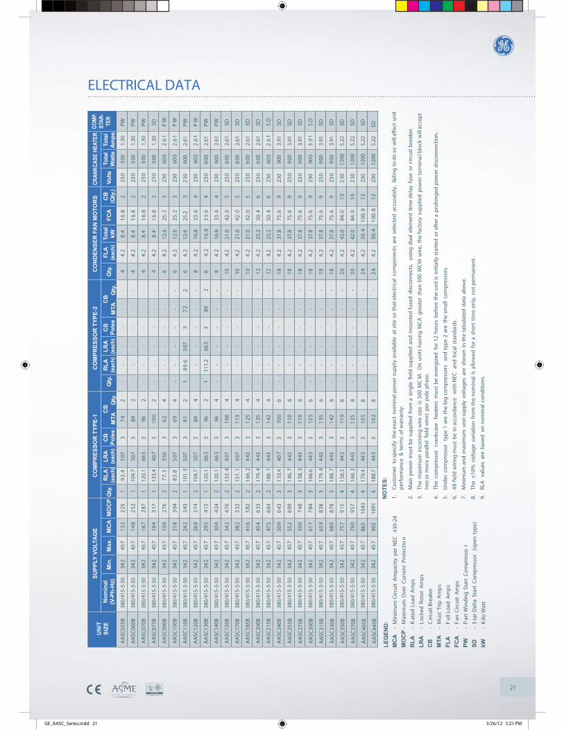
21
ELECTRICAL DATACR
ANKC
ASE
HEAT
ER
Tota
lW
atts
Volts
Tota
lA
mps
CB
(Qty
.)FC
ATo
tal
kWFL
A(e
ach)
Qty
.C
BPo
les
LRA
(eac
h)R
LA(e
ach)
Qty
.C
BPo
les
LRA
(eac
h)R
LA(e
ach)
380/
415-
3-50
380/
415-
3-50
380/
415-
3-50
380/
415-
3-50
380/
415-
3-50
380/
415-
3-50
380/
415-
3-50
380/
415-
3-50
380/
415-
3-50
380/
415-
3-50
380/
415-
3-50
380/
415-
3-50
380/
415-
3-50
380/
415-
3-50
380/
415-
3-50
380/
415-
3-50
380/
415-
3-50
380/
415-
3-50
380/
415-
3-50
380/
415-
3-50
380/
415-
3-50
380/
415-
3-50
380/
415-
3-50
380/
415-
3-50
380/
415-
3-50
AA
SC05
5B
AA
SC06
0B
AA
SC07
0B
AA
SC07
5B
AA
SC09
0B
AA
SC10
0B
AA
SC11
0B
AA
SC12
0B
AA
SC13
0B
AA
SC14
0B
AA
SC15
0B
AA
SC17
0B
AA
SC18
5B
AA
SC20
0B
AA
SC21
5B
AA
SC24
0B
AA
SC25
5B
AA
SC27
5B
AA
SC30
0B
AA
SC31
5B
AA
SC33
0B
AA
SC35
0B
AA
SC37
0B
AA
SC40
5B
AA
SC44
5B
UN
ITSI
ZE
SUPP
LY V
OLT
AG
EC
OM
PRES
SOR
TYP
E-1
CO
MPR
ESSO
R T
YPE-
2C
ON
DEN
SER
FA
N M
OTO
RS
MO
CP
MC
AM
ax.
Min
.N
omin
al(V
-Ph-
Hz)
342
342
342
342
342
342
342
342
342
342
342
342
342
342
342
342
342
342
342
342
342
342
342
342
342
457
457
457
457
457
457
457
457
457
457
457
457
457
457
457
457
457
457
457
457
457
457
457
457
457
132
225
19
2.4
507
37
42
--
--
--
44
.28.
41
6.8
223
03
001.
30PW
148
252
110
4.7
507
384
2-
--
--
-4
4.2
8.4
16.
82
230
300
1.30
PW
167
287
112
0.1
663
396
2-
--
--
-4
4.2
8.4
16.
82
230
300
1.30
PW
184
317
113
3.4
407
310
02
--
--
--
44
.28.
41
6.8
223
03
001.
30SD
199
276
27
7.3
350
36
24
--
--
--
64
.212
.625
.23
230
600
2.6
1P
W
218
304
28
5.8
507
36
94
--
--
--
64
.212
.625
.23
230
600
2.6
1P
W
242
343
110
1.5
507
38
12
18
9.6
507
37
22
64
.212
.625
.23
230
600
2.61
PW
269
374
210
4.7
507
384
4-
--
--
-8
4.2
16.8
33.6
423
060
02
.61
PW
295
415
112
0.1
663
396
21
111.
266
33
892
84.
21
6.8
33.
64
230
600
2.61
PW
304
424
212
0.1
663
396
4-
--
--
-8
4.2
16.8
33.6
423
060
02.
61PW
342
476
213
3.4
407
31
004
--
--
--
104.
221
.042
.05
230
600
2.61
SD
382
533
215
1.1
407
31
134
--
--
--
104.
221
.042
.05
230
600
2.61
SD
416
582
21
66.2
443
31
254
--
--
--
104
.221
.042
.05
230
600
2.61
SD
454
633
21
79.4
443
31
354
--
--
--
124
.225
.250
.46
230
600
2.61
SD
475
664
218
8.7
443
31
424
--
--
--
124.
225
.250
.46
230
600
2.6
1S
D
509
643
31
33.4
407
310
06
--
--
--
184
.237
.875
.69
230
900
3.91
SD
552
699
31
46.7
443
31
106
--
--
--
184
.237
.875
.69
230
900
3.91
SD
590
748
31
58.3
443
31
196
--
--
--
184
.237
.875
.69
230
900
3.91
SD
617
784
31
66.6
443
312
56
--
--
--
184
.237
.875
.69
230
900
3.9
1S
D
659
838
31
79.4
443
31
356
--
--
--
184
.237
.875
.69
230
900
3.91
SD
689
878
31
88.7
443
31
426
--
--
--
184
.237
.875
.69
230
900
3.91
SD
757
915
41
58.3
443
311
98
--
--
--
204
.242
.084
.01
02
3012
005.
22SD
790
957
41
66.2
443
31
258
--
--
--
204
.242
.084
.01
02
3012
005.
22SD
863
1043
417
9.4
443
313
58
--
--
--
244
.250
.41
00.8
12
230
1200
5.22
SD
903
1091
418
8.7
443
314
28
--
--
--
244
.250
.41
00.8
12
230
1200
5.22
SD
Qty
.
COM
P.ST
AR-
TER
Qty
.M
TAC
BQ
ty.
MTA
CB
NO
TES:
1.C
usto
mer
to
spec
ify t
he e
xact
nom
inal
pow
er s
uppl
y av
aila
ble
at s
ite s
o th
at e
lect
rical
com
pone
nts
are
sele
cted
acc
urat
ely,
fai
ling
to d
o so
will
aff
ect
unit
perf
orm
ance
& t
erm
s of
war
rant
y.
2.M
ain
pow
er m
ust
be s
uppl
ied
from
a s
ingl
e fie
ld s
uppl
ied
and
mou
nted
fuse
d di
scon
nect
s,
usin
g du
al e
lem
ent
time
dela
y fu
se o
r ci
rcui
t br
eake
r.
3.Th
e m
axim
um in
com
ing
wire
siz
e is
500
MC
M.
On
units
hav
ing
MC
A g
reat
er t
han
500
MC
M w
ire, t
he fa
ctor
y su
pplie
d po
wer
ter
min
al b
lock
will
acc
ept
two
or m
ore
para
llel
field
wire
s pe
r po
le p
hase
.
4.Th
e co
mpr
esso
r cr
ankc
ase
heat
ers
mus
t be
ene
rgiz
ed f
or 1
2 ho
urs
befo
re t
he u
nit i
s in
itial
ly s
tart
ed o
r af
ter
a pr
olon
ged
pow
er d
isco
nnec
tion.
5.U
nder
com
pres
sor
type
1 a
re t
he b
ig c
ompr
esso
rs
and
type
2 a
re t
he s
mal
l co
mpr
esso
rs.
6.A
ll fie
ld w
iring
mus
t be
in a
ccor
danc
e w
ith N
EC
and
loca
l st
anda
rds
.
7.M
inim
um a
nd m
axim
um u
nit s
uppl
y vo
ltage
s ar
e sh
own
in th
e ta
bula
ted
data
abo
ve.
8.Th
e ±
10%
vol
tage
var
iatio
n fr
om th
e no
min
al is
allo
wed
for
a s
hort
tim
e on
ly, n
ot p
erm
anen
t.
9.RL
A v
alue
s ar
e ba
sed
on n
omin
al c
ondi
tions
.
LEG
END
:M
CA
-M
inim
um C
ircui
t A
mpa
city
per
NEC
43
0-24
MO
CP
-M
axim
um O
ver
Cur
rent
Pro
tect
ion
RLA
-R
ated
Loa
d A
mps
LRA
-L
ocke
d Ro
tor
Am
ps
CB
-C
ircui
t Bre
aker
MTA
-M
ust
Trip
Am
ps
FLA
-F
ull L
oad
Am
ps
FCA
-F
an C
ircui
t A
mps
PW-
Par
t W
indi
ng S
tart
Com
pres
sor
SD-
Sta
r D
elta
Sta
rt C
ompr
esso
r (o
pen
type
)
kW-
Kilo
Wat
t
GE_AASC_Series.indd 21 3/26/12 5:21 PM
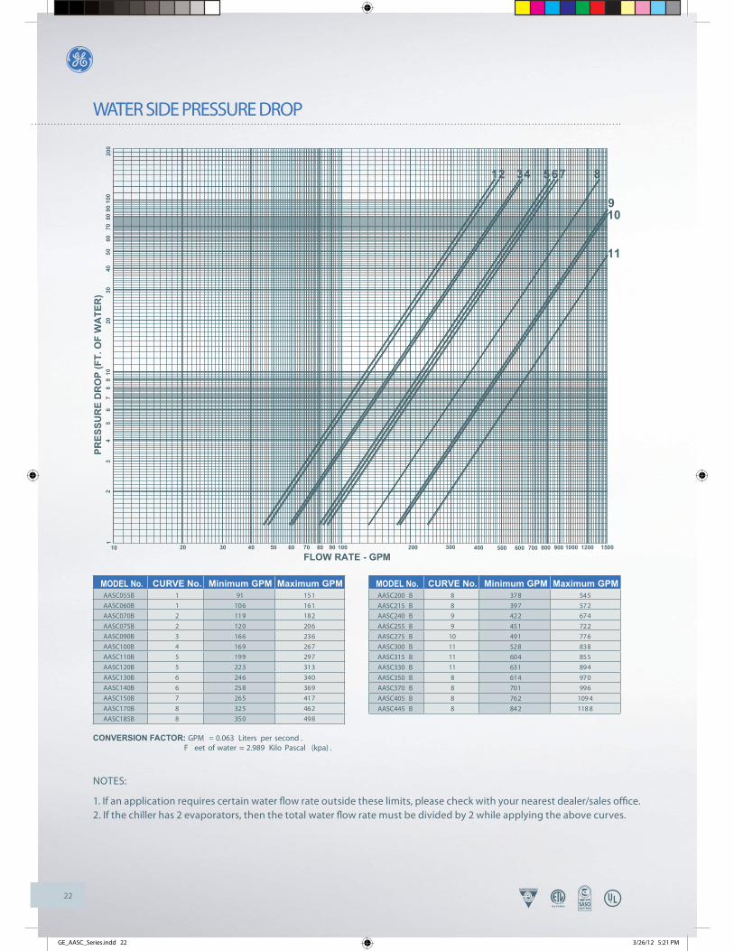
22
WATER SIDE PRESSURE DROP
11
109
8765421 3
PRES
SUR
E D
RO
P (F
T. O
F W
ATE
R)
1
10 20
23
48
06
601
97
35
005
0240
7010
090
8020
0
FLOW RATE - GPM604030 50 9070 80 100 300200 400 500 600 15001000800700 900 1200
CURVE No. Maximum GPM MODEL No.AASC055BAASC060BAASC070B
AASC075BAASC090BAASC100BAASC110B
AASC120B
AASC130B
AASC140B
AASC150B
AASC170B
AASC185B
112
2345
5
6
6
7
8
8
151161182
206236267297
313
340
369
417
462
498
Minimum GPM91
106119
120166169199
223
246
258
265
325
350
CONVERSION FACTOR: GPM = 0.063 Liters per second . F eet of water = 2.989 Kilo Pascal (kpa) .
CURVE No. Maximum GPM MODEL No.AASC200 BAASC215 BAASC240 B
AASC255 BAASC275 BAASC300 BAASC315 B
AASC330 B
AASC350 B
AASC370 B
AASC405 B
AASC445 B
545572674
722776838855
894
970
996
109 4
118 8
Minimum GPM378397422
451491528604
631
614
701
762
842
889
9101111
11
8
8
8
8
NOTES:
1. If an application requires certain water fl ow rate outside these limits, please check with your nearest dealer/sales offi ce. 2. If the chiller has 2 evaporators, then the total water fl ow rate must be divided by 2 while applying the above curves.
GE_AASC_Series.indd 22 3/26/12 5:21 PM

23
DIMENSIONS
NOTE: 1. Cooler dimensions are subject to chenge without notice. Final dimensions will be provided upon order placement. 2. All dimensions are in mm, unless otherwise specified.
AASC055B, AASC060B, AASC070B & AASC075B
AASC090B, AASC100B & AASC110B
MODEL A B
AASC055B - AASC070B 2260 360
AASC075B 3124 800
DIMENSIONS
GE_AASC_Series.indd 23 3/26/12 5:21 PM
2486

24
DIMENSIONS
AASC120B, AASC130B & AASC140B
AASC150B, AASC170B & AASC185B
MODEL A B C
AASC120B 2486 940 342
AASC130B - AASC140B 2450 960 372
DIMENSIONS
MODEL A B C
AASC150B - AASC170B 2450 1880 372
AASC185B 2360 190 0 412
DIMENSIONS
GE_AASC_Series.indd 24 3/26/12 5:21 PM
NOTE: 1. Cooler dimensions are subject to chenge without notice. Final dimensions will be provided upon order placement. 2. All dimensions are in mm, unless otherwise specified.
2486

25
DIMENSIONS
NOTE: 1. Cooler dimensions are subject to chenge without notice. Final dimensions will be provided upon order placement. 2. All dimensions are in mm, unless otherwise specified.
AA
SC20
0B &
AA
SC21
5B
MO
DEL
A
AA
SC20
0B
231
5
AA
SC21
5B24
65
DIM
ENSI
ON
S
GE_AASC_Series.indd 25 3/26/12 5:21 PM
443
2412
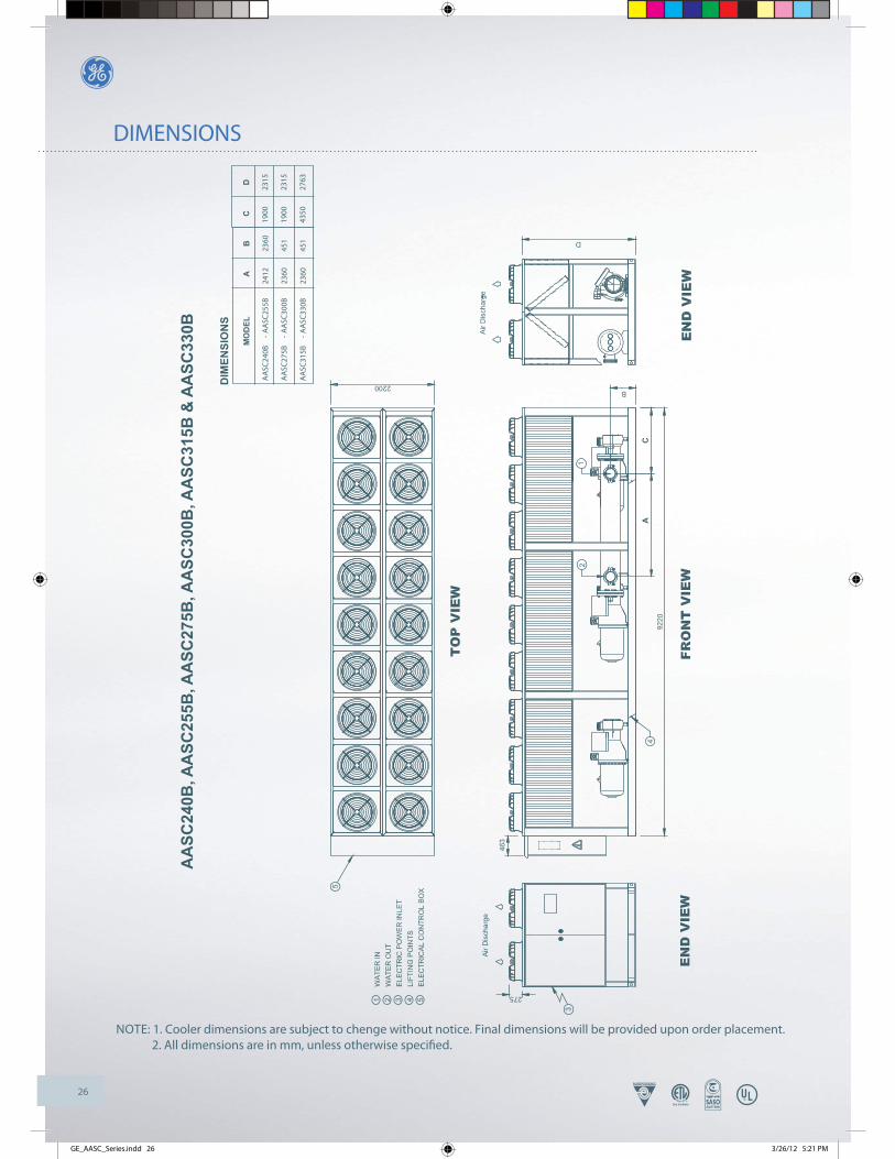
26
DIMENSIONS
NOTE: 1. Cooler dimensions are subject to chenge without notice. Final dimensions will be provided upon order placement. 2. All dimensions are in mm, unless otherwise specified.
AA
SC24
0B, A
ASC
255B
, AA
SC27
5B, A
ASC
300B
, AA
SC31
5B &
AA
SC33
0B
D
GE_AASC_Series.indd 26 3/26/12 5:21 PM
MO
DEL
A
AC
B
AA
SC24
0B
- A
ASC
255B
2412
2360
AA
SC27
5B
- A
ASC
300B
2360
451
AA
SC31
5B
- A
ASC
330B
2360
451
DIM
ENSI
ON
S
CD
1900
2315
1900
2315
4350
2763

27
DIMENSIONS
NOTE: 1. Cooler dimensions are subject to chenge without notice. Final dimensions will be provided upon order placement. 2. All dimensions are in mm, unless otherwise specified.
AA
SC35
0B &
AA
SC37
0B
GE_AASC_Series.indd 27 3/26/12 5:21 PM

28
DIMENSIONS
NOTE: 1. Cooler dimensions are subject to chenge without notice. Final dimensions will be provided upon order placement. 2. All dimensions are in mm, unless otherwise specified.
AA
SC40
5B &
AA
SC44
5B
GE_AASC_Series.indd 28 3/26/12 5:21 PM
2412
2412
1931
3507
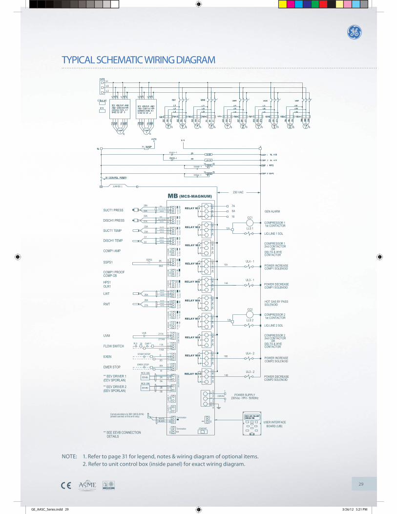
29
TYPICAL SCHEMATIC WIRING DIAGRAM
NOTE: 1. Refer to page 31 for legend, notes & wiring diagram of optional items. 2. Refer to unit control box (inside panel) for exact wiring diagram.
DIGITALANALOG
+5 GND SI
COMP1 PROOF
UL3 - 2W
** SEE EEVB CONNECTIONDETAILS
Communications to SB1 (MCS-SI16)
(EEV SPORLAN)** EEV DRIVER 2
(EEV SPORLAN)** EEV DRIVER 1
MCS-1B6
MCS-1B6
EEVB2
EEVB1
+ - GND
+ - GND
Termination
+ - GND
BLACK
ETHERNET
RS232
USER INTERFACEBOARD (UIB)
230VAC
230 VAC
PO
WER
IN
TerminationWHITE
RELAY M-10
GND Vout5B
5A2A
2B
GND Vout
POWER SUPPLY
2230Vac -1PH - 50/60Hz
1
14B
COMP2 SOLENOIDPOWER DECREASE
FLOW SWITCH
EMER STOP
EXENSTART/STOP
EMER STOP
UVMUVR
CWP *FLS 10
RWT26A
27A
HPS1OLR1
LWT
COMP CB
25A
+5 GND SI+5 GND SI
RELAY M-9
11AA
+5 GND SI
2G
WA
+5 GND SI
G
RELAY M-8
ANALOGDIGITAL
211A
11A
211AA
+5 GND SI
CONTACTOR
UL4 - 215B POWER INCREASE
COMP2 SOLENOID
LIQ LINE 2 SOL
2nd CONTACTOR
DELTA & WYE OR
COMPRESSOR 2
RELAY M-6
RELAY M-7
ANALOGDIGITAL
+5 GND SI
BLACKSHIELDWHITE
DIGITALANALOG
+5 GND SI
RELAY M-5ANALOGDIGITAL
ANALOGDIGITAL
+5 GND SI+5 GND SI
WHITE
BLACKSHIELD
CC2
LLS 212B
SOLENOID
COMPRESSOR 21st CONTACTOR
HOT GAS BY PASS
UL3 - 114A POWER DECREASE
COMP1 SOLENOID
COMP1 AMP
SSPS1SSPS1
DISCH1 TEMP
SUCT1 TEMP22A
C1
23A
D1
SUCT1 PRESS
DISCH1 PRESS
29A
30A
28A
31A
JUMPER 1
COMPRESSOR 11st CONTACTOR
+5 GND SI
RELAY M-4
DIGITALANALOG
DIGITALANALOG8AA
8A
+5 GND SI
RELAY M-3
RELAY M-2
DIGITALANALOG
+5 GND SI
SHIELD
BLACK
WHITE
BLACK
DIGITALANALOG
WHITESHIELD
+5 GND SI
OR
UL4 - 115A
DELTA & WYE CONTACTOR
POWER INCREASECOMP1 SOLENOID
LLS 112A
2nd CONTACTORCOMPRESSOR 1
LIQ LINE 1 SOL
MB
RELAY M-1DIGITALANALOG
BLCK/SHIELD
RED
RED
WHITEBLCK/SHIELD
+5 G ND SI
WHITE
+5 GND SI
DIGITALANALOG
COM NO NC
(MCS-MAGNUM)
6A
CC116
7AGEN ALARM
GND Vout GND Vout
COM NO NCCOM NO NC
COM NO NCCOM NO NC
COM NO NCCOM NO NC
230 VAC
GE_AASC_Series.indd 29 3/26/12 5:21 PM

30
TYPICAL SCHEMATIC WIRING DIAGRAM
+5 GND SI
SHIELDBLACK
WHITE
WHITE
CB
DB
+5 GND SI
+5 GN D SI+5 GND SI
AN ALOGDIGITAL
DIGITAL
ANALOGDIGITAL
DIGITALANALOG
ANALOG
+5 GND SI+5 GND SI
ANALOGDIGITAL
DIGITALANALOG
ANALOGDIGITAL
DIGITALANALOG
SB1RED +5 GND SI
+5 GND SI
WHITE
REDBLCK/SHIELD
WHITE
BLACK
31B
30B
29B
22BSHIELD
BLCK/SHIELD
28B +5 GND SI+5 GND SI
ANALOGDIGITAL
DIGITALANALOG
ANALOGDIGITAL
ANALOGDIGITAL
(MCS-SI16-230)
LIQUID
SOLENOIDINJECTION 2
230 VAC
PO
WER
IN
Termination2
ANALOGDIGITAL
DIGITALANALOG
1
230VAC
DISCH2 PRESS
SUCT2 TEMP
DISCH2 TEMP
SSPS2
COMP2 AMP
COMP CBCOMP2 PROOF
SUCT2 PRESS
ANALOGDIGI TAL
DIGITA L
+5 GND SI
ANALOG
23B
+5 GND SI+5 GN D SI
8BSSPS2
+5 GND SI
8BB
+5 GND SI
+5 GND SI
HPS2OLR2
LI 1LIQUID
SOLENOIDINJECTION 1
(MCS-RO8-230)SB2
20A
RELAY 1-1
COM NO NC
RELAY 1-5
COM NO NC
20B
+ - GND
Communications to SB2 (MCS-RO8)
BLACKWHITE
Communications to MB (MCS-MAGNUM)
FMC6
FMC7
FMC8
FMC10
FMC9
SETTING TEMP = 36degF
EXTERNAL DEVICE
RELAY M-6
MB (MCS-MAGNUM)
HTR1 SB1(MCS-SI13-230)
102B
103B
+5 GND SI
DIGITALAN ALOG
HGBPHOT GAS BY PASSSOLENOID
15 MB (MCS-MAGNUM)
102A
103A
+5 GND SI
DIGITALANALOG
FMC2
FMC1
FMC4
FMC3
FMC5
Communications to SB1 (MCS-SI16)
FAN 9
FAN 1
FAN 3
FAN 7
FAN 5
RELAY 1-8RELAY 1-4
WHITE
BLACK
Termination
+ - GN D
TK1110 21A
COM NO NC
1
230VAC
2
230 VAC
PO
WER
IN
POWER SUPPLY230Vac -1PH - 50/60Hz
21B
COM NO NC
111TK2
RELAY 1-3
19ATK7116
118 TK9
COM NO NC
18A
TK3
TK5114
112
COM NO NC
RELAY 1-2
RELAY 1-7
19B
COM NO NC
117TK8
119TK10
COM NO NC
RELAY 1-6
115
113TK4
TK618B
FAN 10
FAN 2
FAN 4
FAN 8
FAN 6
POWER SUPPLY230Vac -1PH - 50/60Hz
LI 2
CT1
230 VAC
COMP AMP1
CT2COMP AMP2230 VAC
HEATER TAPE
COM NO NC
NOTE: 1. Refer to next page for legend, notes & wiring diagram of optional items. 2. Refer to unit control box (inside panel) for exact wiring diagram.
GE_AASC_Series.indd 30 3/26/12 5:21 PM

31
TYPICAL SCHEMATIC WIRING DIAGRAM
12B
SB1(MCS-SI13-230)
CB4A-1
OLR2A-1
CB2A-122B
10BHPS2
COMP CB
OLR2HPS2
COMP2 PROOF
+5 GND SI
ANALOGDIGITAL
ANALOGDIGITAL
+5 GND SI
COMP2 FM
COMP2
FAN7FAN8
CONTROL PANEL FAN5FAN6
FAN1FAN2 FAN4
FAN3
COMP1 FM
CONTROL PANEL
COMP1
CCA3-1ACB1A-1 +5 GND SI
22A
10A
22B
10B
CB2A-1
HPS2HPS2OLR2
COMP CBCOMP2 PROOF
HPS1HPS1OLR1
COMP1 PROOFCOMP CB
DIGITALDIGITAL
ANALOG
+5 GND SI
OLR2A-1
CCA4-1A110B
110BB
11B
9BB
ANALOG
+5 GND SI
DIGITAL
SB1(MCS-SI13-230)
DIGITAL
110A
+5 GND SI
ANALOG
OLR1A-1
9AA
11A
110AA
ANALOG
CC3A-2
CC5A-2
CC6A-2
CC4A-2
RELAY M-8
12B
RELAY M-3
MB (MCS-MAGNUM)
61BCC4
62BCC6
CC5
61ACC3
62A
12AMB (MCS-MAGNUM)
2
110B23BCCA4-1A
9B11B
9BB
OLR4A-1110BB
CC2A-1
OLR1A-1
CB3A-1CB1A-122A
10AHPS1
HPS1OLR1
COMP CBCOMP1 PROOF
RELAY M-8
CCA3-1A
DIGITALANALOG
+5 GND SI
DIGITALANALOG
+5 GND SI
23A
9A11AOLR3A-1
110A
110AA
9AA
MB (MCS-MAGNUM)
61BCC4
CC1A-1
12A
RELAY M-3
MB (MCS-MAGNUM)2
CC361A
230 VAC
2nd CCFOR COMP #1
COM NO NC
230 VAC
2nd CCFOR COMP #2
COM NO NC
WYE CCFOR COMP #1
FOR COMP #1DELTA CC
WYE CCFOR COMP #2
FOR COMP #2DELTA CC
230 VAC
COM NO NCCOM NO NC
230 VAC
LEGEND
CB CIRCUIT BREAKER
COM P C OMPRESSOR
CC COMPRESSOR CONTACTO R
CC A C OMPRESSOR CONTACTOR AUXILIARY
CWP CHILLED WATER PUMP
DISC H D ISCHARG E
ETB EARTH TERMINAL BLOCK
EE V E LECTRONIC EXPANSIOV VALV E
EEVB ELECTRONIC EXPANSIOV VALVE BOAR D
EXEN REMOTE ENABLE/DISABLE
F F US E
FL S F LOW SWITCH
FM FAN MOTOR
FMC FAN MOTOR CONTACTO R
GND ELECTRICAL GROUNDING
HPS HIGH PRESSURE SWITCH
HGBS HOT GAS BYPASS SOLENOID
HTR COMPRESSOR CRANKCASE HEATER
HVTB HIGH VOLTAGE TERMINAL BLOCK
HZ HERTZ (ELECTRICAL FREQUENCY)
L... LINE (ELECTRICAL POWER LINE/PHASE )
LI LIQUID INJECTION SOLENOID
LLS LIQUID LINE SOLENOID
LW T L EAVING WATER TEMPERATUREMB MASTER BOARDMC S MICROPROCESSOR CONTROL SYSTE MNTB NEUTRAL TERMINAL BLOC KOLR OVER LOAD RELAY
PT PRESSURE TRANSDUCER
PH PHASE (ELECTRICAL PHASE)
RWT RETURN WATER TEMPERATUR E
SB SLAVE BOAR D
S1 CONTROL SWITCH
SSP S S OLID STATE PROTECTION SYSTEM
SUCT SUCTIO NTK FAN MOTOR THERMAL CONTAC TTRANS TRANSFORMERTS TEMPERATURE SENSOR
UL UNLOADERUVM UNDER VOLTAGE MONITO R
UVR UNDER VOLTAGE RELA YTERMINAL BLOCK OR TERMINATION POIN T
- - - - - FIELD WIRING
* FIELD SUPPL Y
TERMINATION JUMPER IS CLOSED
TERMINATION JUMPER IS OPEN
NOTES1. POWER SUPPLY, 380/415V-3Ph-50Hz .
ALL FIELD WIRING TO COMPLY WITH LOCAL CODES.
2. FUSES TO DUAL ELEMENT TYPE .
3. USE COPPER CONDUCTORS ONLY.
4. FUSED DISCONNECT SWITCH OR CIRCUIT BREAKERTO BE PROVIDED BY END USER WITH RATING ASRECOMMENDED BY MANUFACTURER.
5. POWER MUST BE SUPPLIED TO CRANKCAS EHEATER FOR MINIMUM OF 12 HOURS PRIOR TOSYSTEM START UP .IF POWER IS OFF 6 HOURS OR MORE, CRANKCASEHEATER MUST BE ON FOR 12 HOURS BEFOR EOPERATING THE SYSTEM .
FAILURE TO FOLLOW THESE INSTRUCTIONS MAYRESULT IN COMPRESSOR DAMAGE.
6. MARK THE BOX AT THE UPPER RIGHT CORNER OFTHE RESPECTIVE OPTIONAL ITEM, IF THE OPTIONA LITEM IS INCLUDED IN THE UNIT .
GE_AASC_Series.indd 31 3/26/12 5:21 PM
32
MICROPROCESSOR CONTROLLER
SEQUENCE OF OPERATIONFor Initial start up of the unit, the following conditions must be met:
1. Power to the unit shall be continuously energized for 12 hours minimum.
2. Control power has been accomplished and the display shows no alarm.
3. All safety conditions are satisfied.
4. Chilled water pump is running normal and chilled water flow switch contact is closed.
5. Customer control or remote on/off is switched to run mode, if any.
Staging ON and OFF sequence is accomplished based on the controlled water temperature. Using the stepless compressor capacity control (called slider), the controller will drive the slider to maintain the required demand as constant as possible.
COMPRESSOR STAGE – ON SEQUENCEStage-1:
If the controlled water temperature is above the water temperature set point the fi rst compressor or the compressor with less running hours will start by unloading for certain second. A� erwards, slider will move then to part load or to full capacity of the compressor depends upon the required load demand of the unit.
As the discharge pressure of the running compressor rises, the corresponding fan will turn ON accordingly to its fan stage – ON set point. If the discharge falls below the fan stage – OFF set point value, the corresponding fan then will turn OFF.
Stage-2:
A� er such time delay. If the controlled water temperature is still above from the water temperature set point. The 2nd
compressor or the next less running hours compressor will start by unloading for certain time. Then the slider will move to part load or to full capacity of the compressor depends upon on the load demand of the unit.
As the discharge pressure of the 2nd compressor rises, the corresponding fan at the 2nd circuit will turn ON accordingly to its fan stage – ON set point. If the discharge falls below the fan stage – OFF set point value, the corresponding fan then will turn OFF.
For the unit with more than two refrigerant circuits, all compressor staging will be the same as illustrated above. For the unit with one circuit, the staging will based from the part load to the full capacity of the compressor.
COMPRESSOR STAGE – OFF SEQUENCEDuring the staging OFF, the FIFO (First-In First-Out) sequence is adopted as standard. If the compressor equalization is not activated the LIFO (Last-In First-Out) then will be adopted.
As the demand load decreases and when the water temperature falls below the water temperature set point. The fi rst compressor or the compressor with most running hours will then start unloading. If the water temperature continuously falls below the set point the fi rst compressor then will turn OFF.
If the water temperature still below the set point the next compressor with most running hours will start unloading, then OFF.
GE_AASC_Series.indd 32 3/26/12 5:21 PM
33
MICROPROCESSOR CONTROLLER
The controller consists of the following hardware:
1. User Interface Board (UIB): the display board – LCD with user friendly control push buttons. 2. Main Board Controller: Equipped with advanced logic to safely operate the chiller and run at its most efficiency. 3. Auxiliary Board Controller: Only when applicable, this serves as an extension of analog and digital I/O’s.4. Electronic Expansion Valve Board: Communicate with the Main Board to control the electronic expansion valve at its
high efficient and performance.5. Sensors: The devices that feeding inputs to the controller.
Display Information:
Easily accessible measurements for unit and each circuit include the following:
1. Circuit suction and discharge pressure 2. Circuit suction and discharge temperature 3. Leaving and return water temperature4. Compressor amps percentage 5. Compressor status 6. Compressor drawn Ampere 7. Fan status8. Solenoid status 9. Expansion Valve status 10. Circuit Suction and Discharge Superheat value 11. Current Unit Cooling Capacity Status 12. Current Circuit Cooling Capacity Status 13. Ambient Temperature (optional) 14. Lockouts and 60 History of Alarms 15. Target temperature set point 16. Sensor input/output set up 17. Real Time Graphical Display 18. Analog and Digital Input/output Status 19. Circuit Suction and Discharge Saturated Value 20. Unit Cooling and Expansion Valve Rate of Change
System Protection:
The following system protection is provided to insure system reliability:
Chiller Unit Standard Lockouts:
1. Freeze Protection 2. No Water Flow Protection3. Phase Loss Protection 4. Over and Under Voltage Protection 5. Serial Communication Error
Compressor Circuit Safeties and Lockouts:
1. Compressor Motor Winding Overheating 2. Low Suction Pressure 3. High and Low Discharge Pressure 4. High Discharge Temperature5. High and Low Motor amps 6. Sensors Error 7. Anti recycle time delay for compressor
GE_AASC_Series.indd 33 3/26/12 5:21 PM

34
MICROPROCESSOR CONTROLLER
Microprocessor Control System (MCS) Main Feature provides the following:
1. A special software was been developed for air cooled chiller application with screw compressors.2. Compressor Lead / Lag operation. This is to balance the run hours operation of every compressor in the chiller unit.3. The user interface board is having 9 user friendly push buttons with simple identification for easy accessing the data
and information from the display.4. The controller is equipped with self diagnostic functions. That in case of any errors, it will give an alarm and shut off
only the affected circuit or the whole unit if necessary. The full description of the alarm/error is visible in the display.5. A special control zone based on the Leaving or Return Water Temperature that leads the compressor function to
maintain the unit capacity at its target set point.6. A flexible authorization levels is available. This is to maximize the security on the control system.7. Thru Volt free contact, the chiller unit can be remotely enable/disabled.8. Energy efficient compressor staging for multi screw compressor chiller unit. This provides the user with additional
capabilities in fine tuning the efficiency of the screw compressor.9. Adaptive capacity control where the controller takes the necessary corrective action when reached at critical status
of temperature or pressure in the circuit prior to a safety being tripped.10. Compressor ampere is monitored continuously by the controller, for safety operation and its properly locates the
position of the compressor slider.11. BMS protocol like Bacnet, Modbus, Johnson Control and Lonworks are available, it can configure from the controller
set up menu and can be connected thru its available port in the controller board.12. A windows based program (MCS-Connect) was installed to monitor and access all data at the microprocessor using
a windows based computer for easy servicing.13. In an occurrence of lockouts/alarm, the last reading of every sensors are logged in the microprocessor and it can be
viewed using the UIB or a PC.14. Seven days operating schedule plus holidays can be encoded or programmed to the controller to ON and OFF the
chiller unit accordingly.15. Components are UL approved as standard.16. The controller automatically performs a 144 data logging of all I/Os signal and saved it into the microprocessor; this
logged data can be presented using its built in graphing function.
BMS Interfacing (optional):
A standard on board RS-485 port is provided for interfacing with building management system as well as to communicate both locally and remotely. For more interfacing connectivity also a RS-232 and Ethernet port was provided as standard. The controller can be interfaced to diff erent protocol like Bacnet, Modbus, Johnson Control and Lonworks.
Controller network can support 20 Main Boards and its associated inputs/outputs using the RS-232 or RS-485 connection. Note that RS-232 transmissions should not exceed 50 feet in length and for RS-485 transmission should not exceed 1 mile.
Part of the BMS features. Is the MCS-Connect, this is a PC- support so� ware that was available at the controller. With this features, all the points of each individual refrigerant circuits and unit status, alarms, set points, analog and digital inputs / outputs can be viewed. Also the controller confi guration on the chiller unit can be easily done using a local or remote PC.
PC minimum system requirements to run the program:
Windows 2000; Pentium 1.0 MHz or Faster; 40 GB Hard drive; 256 RAM; 56k Modem & VGA display capable for 256 color.
MCS also provides the Volt free contact connection for BMS:
1. Remote Unit Run and Stop Enable – remotely enable/disable the chiller unit thru volt free contact from the field.2. General Alarm – a volt free contact from the controller that closes when a chiller unit indicates a problem.3. Emergency Stop – a volt free contact when closes from remote it enable the chiller unit to immediately shut down in
case of emergency situation.4. Compressor Run Status – This is a relay output closure from the controller board to the BMS indicating the compressor is running.5. Chiller Water Reset – An analog input (0 to 5 V) supplied to the board from the BMS. A reading of 2.5V will result in a
zero adjustment. A reading of less than 2.5V will result for a negative adjustment, and a greater then 2.5V will result in a positive adjustment.
GE_AASC_Series.indd 34 3/26/12 5:21 PM

35
APPLICATION GUIDELINES
INTRODUCTION
These guidelines should be considered when designing systems and their installation utilizing GE AASC series liquid chillers. Stable operation, performance and reliability of units is off en dependent upon proper compliance with these recommendations. When any application varies from these guidelines, it should be referred with GE Air Conditioners for specifi c recommendations.
UNIT SELECTION/SIZING
Unit selection procedure and capacities are provided in this catalog for proper selection. The GE electronic selection program may also be utilized for this purpose.
Over sizing chillers beyond a maximum limit of 5 – 10 % in order to assure adequate capacity or considering future expansions is not recommended. Over sizing adversely aff ects the operating effi ciency due to erratic system operation and excessive compressor cycling which also results in reduced compressor life. It should be noted that, units operate more effi ciently when fully loaded rather than larger equipment operating at partial capacities. In addition, an oversized unit is usually more costly to purchase, install and operate.
When over sizing is desired due to anticipation of future plant expansion, consider using multiple units. For example, install a single chiller for the present load requirement and install a second chiller for the foreseen additional load demand due to expansion. Further, it is also recommended that installing two chillers instead of a single chiller be considered in applications where partial load operation at low capacities is necessary.
Operation of two chillers at higher loading is preferred to operating a single chiller at or near its minimum possible capacity.
FOULING FACTOR AND WATER REQUIREMENT
The tabulated performance data provided in this catalog are based on a fouling factor of 0.00010 hr-ft2 -°F/Btu (0.000018 m2 -°C/W). As fouling factor is increased, unit capacity decreases and power input increases. For unit selection at other fouling factors, apply appropriate correction factor from the table provided in this catalog.
These chillers are suitable for operation with well maintained water systems. Using unclean and untreated water may result in scale and deposit formation causing reduced cooler effi ciency or heat transfer and corrosion or pitting leading to possible equipment damage. The more scale forming material and suspended solids in the system water, the greater the chances of scale and deposit formation and fouling. These include calcium, magnesium, biological growth (algae, fungi and bacteria), dirt, silt, clays, organic contaminants (oils), silica, etc. which should be kept to the minimum to retard scale and deposit formation. In order to prevent corrosion and pitting, the pH value of the water fl owing through the cooler must be kept between 7 and 8.5. GE recommends that a water treatment specialist is consulted to provide and maintain water treatment, this is particularly critical with glycol systems.
EFFECT OF ALTITUDE ON UNIT CAPACITY
The tabulated performance data provided in this catalog are for use at or near sea level altitude application. At altitudes substantially above sea level, the decreased air density will reduce condenser capacity and therefore unit capacity. For unit selection at these higher altitudes, apply appropriate correction factor from the table provided in this catalog.
HIGH AMBIENT CONSIDERATION
These chillers are designed for year round operation over a range of ambient temperatures. As a standard, these chillers can start and operate satisfactorily up to 125°F (52°C) ambient temperature at rated nominal voltage.
WATER FLOW RATES AND COOLER PRESSURE DROP
The maximum and minimum water fl ow rates for all unit models and the pressure drop chart are provided in this catalog. The design water fl ow rate must be within this range. Design fl ow rates below the minimum limits will result in laminar fl ow causing freeze-up problems, stratifi cation and poor control and fl ow rates beyond the maximum limits cause excessive pressure drop and severe tube erosion.
During unit operation, water fl ow rate must not vary more than ± 5% from the design fl ow rate. The water fl ow switch should be calibrated accordingly. The piping and pumping layout should be right for the application and must assure proper water return and circulation. When using glycol solution, fl ow rate and pressure drop are higher than with water, therefore care must be taken not to exceed the limits. In such applications, consult GE Air Conditioners for specifi c recommendations.
GE_AASC_Series.indd 35 3/26/12 5:22 PM
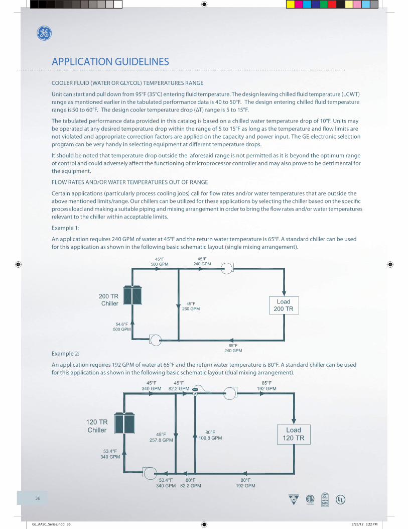
36
APPLICATION GUIDELINES
Load200 TR
200 TRChiller
54.6°F500 GPM
45°F500 GPM
45°F240 GPM
65°F240 GPM
45°F260 GPM
Load120 TR
120 TRChiller
45°F340 GPM
80°F109.8 GPM
45°F257.8 GPM
80°F82.2 GPM
53.4°F340 GPM
80°F192 GPM
65°F192 GPM
53.4°F340 GPM
45°F82.2 GPM
COOLER FLUID (WATER OR GLYCOL) TEMPERATURES RANGE
Unit can start and pull down from 95°F (35°C) entering fl uid temperature. The design leaving chilled fl uid temperature (LCWT) range as mentioned earlier in the tabulated performance data is 40 to 50°F. The design entering chilled fl uid temperature range is 50 to 60°F. The design cooler temperature drop (ΔT) range is 5 to 15°F.
The tabulated performance data provided in this catalog is based on a chilled water temperature drop of 10°F. Units may be operated at any desired temperature drop within the range of 5 to 15°F as long as the temperature and fl ow limits are not violated and appropriate correction factors are applied on the capacity and power input. The GE electronic selection program can be very handy in selecting equipment at diff erent temperature drops.
It should be noted that temperature drop outside the aforesaid range is not permitted as it is beyond the optimum range of control and could adversely aff ect the functioning of microprocessor controller and may also prove to be detrimental for the equipment.
FLOW RATES AND/OR WATER TEMPERATURES OUT OF RANGE
Certain applications (particularly process cooling jobs) call for fl ow rates and/or water temperatures that are outside the above mentioned limits/range. Our chillers can be utilized for these applications by selecting the chiller based on the specifi c process load and making a suitable piping and mixing arrangement in order to bring the fl ow rates and/or water temperatures relevant to the chiller within acceptable limits.
Example 1:
An application requires 240 GPM of water at 45°F and the return water temperature is 65°F. A standard chiller can be used for this application as shown in the following basic schematic layout (single mixing arrangement).
Example 2:
An application requires 192 GPM of water at 65°F and the return water temperature is 80°F. A standard chiller can be used for this application as shown in the following basic schematic layout (dual mixing arrangement).
GE_AASC_Series.indd 36 3/26/12 5:22 PM

37
APPLICATION GUIDELINES
COOLER FREEZE PROTECTION
If the unit is located in an area where ambient temperatures fall below 32°F (0°C), cooler protection in the form of Ethylene Glycol Solution is required to protect the cooler and fl uid piping from low ambient freeze-up. This glycol solution must be added to the water system loop to bring down the freezing point of water to a diff erence of 15°F (8.3°C) below minimum operating ambient temperature.
Using this glycol solution causes a variation in unit performance, fl ow rate and pressure drop, therefore appropriate correction factors from the aforementioned table in this catalog should be applied.
MULTIPLE CHILLER ARRANGEMENT OR PLANT CONFIGURATION
A multiple chiller system has two or more chillers connected by parallel or series piping to a common distribution system. Multiple chiller arrangements off er the advantage of operational fl exibility, standby capacity and less disruptive maintenance. Also, they off er some standby capacity if repair work must be done on a chiller from a set of duty chillers. Starting in-rush current is reduced, as well as power costs at partial-load conditions.
A multiple chiller arrangement should be provided if the system load is greater than a single chiller capacity, standby capability is desired, large temperature drop (greater than 15°F) is desired or application calls for splitting the total capacity for better part load operation.
In designing a multiple chiller plant, units of same size should be preferred over diff erent sizes to facilitate balanced water fl ow. It is mandatory that cooler fl ow rates must be balanced to ensure proper fl ow to each chiller based on its respective capacity. As mentioned above, two basic multiple chiller systems are used: parallel and series chilled water fl ow.
In the parallel arrangement, liquid to be chilled is divided among the liquid chillers; the multiple chilled streams are combined again in a common line after chilling. Water temperatures (EWT or LWT) can be used to cycle units On and Off based on the cooling demand. Parallel arrangements permit adding chillers in the future for plant expansion with the appropriate considerations beforehand.
In the series arrangement, the chilled liquid pressure drop may be higher unless coolers with fewer liquid-side passes or baffl es are used. No over chilling by either unit is required, and compressor power consumption is lower than it is for the parallel arrangement at partial loads. It is also possible to achieve higher overall entering to leaving temperature drops, which may in turn provide the opportunity for lower chilled water design temperature, lower design fl ow and resulting installation and operational cost savings. Series chiller arrangements can be controlled in several ways based on the water temperatures depending on cooling demand.
A valved piping bypass is suggested around each chiller to facilitate future servicing as it gives the personnel an option for service without a complete shutdown.
GE recommends the parallel arrangement for design temperature drops (ΔT) up to 15°F and the series arrangement beyond that i.e., 16 to 20°F. Complete design details on these parallel and series chilled water fl ow arrangements can be found in the ASHRAE handbooks and other design literature which should be referred by the designer in preparing his detailed designs.
PIPING ARRANGEMENTS AND PLANT LAYOUT
Our chillers are suitable for incorporating in ‘Two Pipe’ single temperature systems or ‘Four Pipe’ independent load systems. The system piping circuit (load distribution circuit) should be basically parallel piping either Direct Return or Reverse Return system with a good pumping arrangement.
The method of circuiting and pumping is a judgment decision by the designer. The designer must weigh the pros and cons of cost, nature of load and confi guration of building, energy economics, fl exibility, installation requirements and others to determine the best arrangement for his project. In all cases, it must be ensured that the design water fl ow is constantly maintained through the chillers at all stages of operation. Some suggested arrangements with basic schematic layouts are as follows:
GE_AASC_Series.indd 37 3/26/12 5:22 PM

38
APPLICATION GUIDELINES
CHWS
CHWR
Load Load
3-WayValve
3-WayValve
Constant Speed Pump
Chiller
A. Single or multiple chillers with constant water fl ow through chillers and load system:
In this type of arrangement, constant water fl ow through the chillers and load distribution piping circuit is maintained. Before proceeding further, a brief explanation on the operation of a typical chilled water system / valves which is fundamental to the design or analysis of a system.
Where multiple zones of control are required, the various load devices are controlled fi rst; then the source (chillers) system capacity is controlled to follow the capacity requirement of the loads. Control valves are commonly used to control loads. These valves control the capacity of each load by varying the amount of water fl ow through the load device. Control valves for these applications are two-way (straight-through) and three-way valves. The eff ect of either valve is to vary the amount of water fl owing through the load device. With a two-way valve, as the valve strokes from full-open to full-closed, the quantity of water fl owing through the load gradually decreases from design fl ow to no fl ow. The three-way mixing valve has the same eff ect on the load as the two way valve – as the load reduces, the quantity of water fl owing through the load decreases in proportion to the load and the diff erence amount is directed through a bypass.
In terms of load control, a two-way valve and a three-way valve perform identical functions – they both vary the fl ow through the load as the load changes. The fundamental diff erence between the two-way valve and the three-way valve is that as the source or distribution system sees the load, the two-way valve provides a variable fl ow load response and the three-way valve provides a constant fl ow load response.
Referring to the foregoing schematic layout, this is a conventional system and is not as energy effi cient as the two-way valve systems especially on the pumping side due to constant water circulation in the system. On multiple chiller installations, pumps are required to operate continuously and the sequencing of chillers is dependent on water temperatures.
GE_AASC_Series.indd 38 3/26/12 5:22 PM

39
APPLICATION GUIDELINES
Flow Sensor
CHWR
P
2-Way Valve
Load
CHWSA
B
Variable Speed Secondary Pump
SystemController
Load
2-Way Valve
Constant SpeedPrimary Pump
Chiller
B. Single or multiple chillers with constant water fl ow through chillers and variable water fl ow through load system (primary/secondary pumping arrangement):
This system is called a Primary – Secondary System and in this arrangement, the generation zone is separated from the transportation or distribution zone. In this type of arrangement also, constant water fl ow through the chillers is maintained, however the quantity of water fl owing through the load distribution pump/piping system decreases in proportion to the load and the diff erence amount is directed through a bypass pipe that connects the supply and return headers. This bypass pipe forms a ‘Hydraulic Coupling’ between the points A – B and is also called as Common Bridge or Decoupling Line. The sequence of operation is similar as the foregoing system with the following explanation:
The speed of the secondary chiller pump is controlled by the diff erential pressure sensor/transmitter, maintaining the desired diff erential pressure (ΔT) across the cooling coils, their control valves and the branch piping. This pump speed is modulated within a broad range in order to reduce the pumping head and alter the water fl ow rate based on the changing load conditions.
The primary pumps are constant speed pumps and the design fl ow rate through the chillers remains constant. Each chillerpump combination operates independently from the remaining chillers and each pump is shutdown when the respective chiller is stopped. The sequencing of chillers is dependent on water fl ow. If greater fl ow is demanded than that supplied by the chiller-pumps, return water is forced through the bypass into the supply header. This fl ow indicates a need for additional chiller capacity and another chiller-pump starts. Excess bypass fl ow with reference to the set points in the system controller in the opposite direction i.e., into the return header indicates overcapacity and the chiller-pumps are turned off .
Energy is saved because the system head and water fl ow rate are reduced on the Secondary Pump when there are partial cooling loads on the system and due to cycling of Primary Pumps.
UNIT LOCATION AND INSTALLATION
These chillers are designed for outdoor installation and can be installed at ground level or on a suitable roo� op location. In order to achieve good operation, performance and trouble-free service, it is essential that the proposed installation location and subsequent installing procedures meet the following requirements:
The most important consideration while deciding upon the location of air cooled chillers is the provision for supply of adequate ambient air to the condenser and removal of heated discharge air from the condenser. This is accomplished by maintaining sufficient clearances which have been specified in this Catalog around the units and avoiding obstructions in the condenser air discharge area to prevent the possibility of warm air circulation. Further, the condenser fans are propeller type and are not recommended for use with ductwork or other hindrances in the condenser air stream. Where these requirements are not complied, the supply or discharge airflow restrictions or warm air recirculation will cause higher condensing temperatures resulting in poor unit operation, higher power consumption and possible eventual failure of equipment.
GE_AASC_Series.indd 40 3/26/12 5:22 PM

40
APPLICATION GUIDELINES
The unit’s longitudinal axis should be parallel to the prevailing wind direction in order to ensure a balanced air flow through the condenser coils. Consideration should also be given to the possibility of down-drafts caused by adjacent buildings, which may cause recirculation or uneven unit airflow. For locations where significant cross winds are expected, an enclosure of solid or louver type is recommended to prevent wind turbulence interfering with the unit airflow. When units are installed in an enclosure, the enclosure height should not exceed the height of the unit.
The location should be selected for minimum sun exposure and away from hot air sources, steam, exhaust vents and sources of airborne chemicals that could attack the condenser coils and steel parts of the unit. Avoid locations where the sound output and air discharge from the units may be objectionable.
If the location is an area which is accessible to unauthorized persons, steps must be taken to prevent access to the unit by means of a protective fence. This will help to prevent the possibility of vandalism, accidental damage or possible harm caused by unauthorized removal of panels or protective guards exposing rotating or high voltage components.
The clearance requirements prescribed above are necessary to maintain good airflow and provide access for unit operation and maintenance. However, it is also necessary to consider access requirements based on practical considerations for servicing, cleaning and replacing large components.
The unit must be installed on a ONE-PIECE, FLAT and LEVELLED {within 1/2’’ (13 mm) over its length and width} / CONCRETE BASE that extends fully to support the unit. The carrying or supporting structure should be capable of handling complete operating weight of the unit as given in the Physical Data tables in this Catalog.
For ground level installations, it must be ensured that the concrete base is stable and does not settle or dislocate upon installation of the unit which can strain the refrigerant lines resulting in leaks and may also cause compressor oil return problems. It is recommended that the concrete slab is provided with appropriate footings. The slab should not be connected to the main building foundation to avoid noise and vibration transmission.
For rooftop installations, choose a place with adequate structural strength to safely support the entire operating weight of the unit. The unit shall be mounted on a concrete slab similar to ground installations. The roof must be reinforced for supporting the individual point loads at the mounting isolator locations. It must be checked and ensured that the concrete base is perfectly horizontal and levelled, especially if the roof has been pitched to aid in water removal. It should be determined prior to installation if any special treatment is required to assure a levelled installation else it could lead to the above mentioned problems.
Vibration isolators are necessary for installing these chillers in order to minimize the transmission of vibrations. The two types of vibration isolators generally utilized for mounting these units are Neoprene Pads and Spring Isolators. Neoprene Pads are recommended for ground level normal installations jobs where vibration isolation is not critical and job costs must be kept to a minimum. Spring Isolators are recommended for ground level installations which are noise- sensitive areas or exposed to wind loads and all roof top installations. For critical installations (extremely noise and vibration sensitive areas), follow the recommendations of structural and acoustical consultants.
Based on the specific project requirements, choose the type of vibration isolators best suited for the application. Carefully select the vibration isolators’ models / configuration based on the respective point loads and place each mount in its correct position following the Load Distribution Data and Mounting Drawings provided in this Catalog. Refer to the Schematic Mounting Layout drawings provided in the IOM manual of these chillers for further details in this regard.
COOLER PIPING CONNECTIONS
The following pertinent guidelines are served to ensure satisfactory operation of the units. Failure to follow these recommendations may cause improper operation and loss of performance, damage to the unit and diffi culty in servicing and maintenance:
Water piping must be connected correctly to the unit i.e., water must enter from the inlet connection on the cooler and leave from the outlet connection.
A flow switch must be installed in the field piping at the outlet of the cooler (in horizontal piping) and wired back to the unit control panel using shielded cable. There should be a straight run of piping of at least five pipe diameters on either side of the flow switch. Paddle type flow switches can be obtained from GE which are supplied as optional items.
The chilled water pump(s) installed in the piping system should discharge directly into the unit cooler. The pump(s) may be controlled external to the unit - but an interlock must be wired to the unit control panel (as shown in the wiring diagram) so that the unit can start only upon proof of pump operation.
GE_AASC_Series.indd 41 3/26/12 5:22 PM

41
APPLICATION GUIDELINES
Flexible connections suitably selected for the fluid and pressure involved should be provided as mandatory in order to minimize transmission of vibrations to the piping / building as some movement of the unit can be expected during normal operation. The piping and fittings must be separately supported to prevent any loading on the cooler.
The cooler must be protected by a strainer, preferably of 20 mesh, fitted as close as possible to the liquid inlet connection, and provided with a means of local isolation.
Thermometer and pressure gauge connections should be provided on the inlet and outlet connections of each cooler. Pressure gauges are recommended to check the water pressure before and after the cooler and to determine if any variations occur in the cooler and system. When installing pressure taps to measure the amount of pressure drop across the water side of the cooler, the taps should be located in the water piping a minimum of 24 inches downstream from any connection (flange etc.) but as near to the cooler as possible.
Drain and air vent connections should be provided at all low and high points in the piping system to permit complete drainage of the cooler and piping as well as to vent any air in the pipes. Hand shut-off valves are recommended for use in all lines to facilitate servicing.
The system water piping must be flushed thoroughly before connecting to the unit cooler. The cooler must not be exposed to flushing velocities or debris released during flushing. It is recommended that a suitably sized bypass and valve arrangement is installed to allow flushing of the piping system. The bypass can be used during maintenance to isolate the cooler without disrupting flow to other units.
The following is a suggested piping arrangement at the chiller for single unit installations. For multiple chiller installations, each unit should be piped as shown:
OUT
IN
Isolating Valve - Normally Open
Isolating Valve - Normally Closed
Balancing Valve
Flow meter
Strainer
Pressure tapping
Flow Switch
Connection (�anged / Victaulic)
Pipe work
Flexible connection
Note: For chillers with two coolers, the connecting pipes for entering and leaving water on one cooler must be joined to the corresponding pipes on the other cooler before connecting to the main headers in the system piping.
GE_AASC_Series.indd 42 3/26/12 5:22 PM

42
APPLICATION GUIDELINES
CHILLED FLUID VOLUME REQUIREMENT
The volume of water in a piping system loop is critical to the smooth and proper operation of a chilled water system. If suffi cient volume of water is not there in the system, the temperature control can be lost resulting in erratic system operation and excessive compressor cycling. Therefore, to prevent this eff ect of a ‘Short Water Loop’ ensure that total volume of water in the piping system loop equals or exceeds 3 Gallons per Nominal Ton of cooling capacity for standard air conditioning applications and 6 Gallons per Nominal Ton of cooling capacity for process cooling jobs where accuracy is vital and applications requiring operation at very low ambient temperatures and low loading conditions.
For example, chiller model AASC100B operating with a design water fl ow rate of 205 GPM for a standard air conditioning application would require 100 (Nom. Cap.) x 3 = 300 Gallons of water in the piping system loop.
To achieve the aforementioned water volume requirements, it may be necessary to install a tank in the piping system loop to increase the volume of water in the system and therefore, reduce the rate of change of return water temperature. This tank should be provided on the return water side to the chiller and the tank should be baffl ed to ensure that there is no stratifi cation and the entering stream thoroughly mixes with the tank water. See recommended tank design schematics below:
TANK SCHEMATIC
SUGGESTIONS ON SYSTEM DESIGN AND PIPING PRACTICES
The prospective chilled water system should be designed to the specifi c requirements of the owner and to achieve the most effi cient system possible. Following are some recommendations:
The first decision a designer of a chilled water system must make is the selection of the temperature differential. Temperature differential is the difference between the supply water and the return water temperatures. There is no one temperature difference for all chilled water systems. The actual temperature difference that is selected for a specific installation is determined by the cost of the cooling coils for various temperature differences and the effect that higher differences may have on the operating cost of the chillers. A careful balance between energy savings and first cost should be made by the designer. These are the decisions that must be made by the designer for each application and only experienced designers should entertain water temperature differences in excess of 12°F on chilled water systems. A number of conditions must be recognized before making the final selection of temperature differential:
a) An increase in temperature differential decreases water flow and therefore saves pumping energy.
b) An increase in temperature differential may increase the cost of cooling coils that must operate with a higher mean temperature difference.
c) Higher temperature differentials increase the possibilities of loss of temperature difference in coils due to dirt on the air side and chemical deposits on the water side of them.
d) Laminar flow on the water side due to lower velocities at low loads on a coilisal ways a concern of the water system designer. The possibility of laminar flow is greater with higher temperature differences. Laminar flow reduces the heat-transfer rate and should not occur in a coil at any point in its load range. Many systems operate inefficiently because of coils that were selected at too low a friction loss through them at design load; therefore, at reduced loads and flows, they operate with laminar flow.
GE_AASC_Series.indd 43 3/26/12 5:22 PM
43
APPLICATION GUIDELINES
Control of Return Water Temperature: Return water temperature is one of the most important operating values for a chilled water system. It tells the operator just how good a job the control system and coils are doing in converting energy from the chillers to the air or water systems that are cooling the building. This is such a basic criterion that it should be addressed early in the design of a chilled water system. The proper method of controlling return temperature is through the correct selection of control valves and cooling coils. In conclusion, one of the designer’s most important tasks is the selection of a sound temperature differential that will provide maximum possible system efficiency. The second step in this process is to ensure that the differential is maintained after the system is commissioned.
The water system should be configured to distribute the water efficiently with a minimum use of energy-wasting devices. These devices are listed here:
a) Three-way temperature control valves.
b) Balancing valves, manual or automatic.
c) Pressure-reducing or pressure-regulating valves.
The piping should be designed without:
a) Reducing flanges or threaded reducing couplings.
b) Bullhead connections (e.g., two streams connected to the run connections of a tee with the discharge on the branch of the tee).
The friction for the piping should be calculated for all pipe runs, fittings and valves.
Cooling coils should be selected with a high enough water velocity in the tubes to avoid laminar flow throughout the normal load range imposed on the coils.
Coil control valves and their actuators should be sized to ensure that they can operate at all loads on the system without lifting the valve head off the valve seat.
Expansion tank should be provided to so that water volume changes can be accommodated. Expansion tanks are generally connected to the suction side of the pump - lowest pressure point.
Pumps in parallel must always operate at the same speed. There may be some exceptional cases where parallel pumps are operated at different speeds, but only experienced designers should make evaluations for such a proposed operation. Also, it is better to use pumps of the same size when operating them in parallel. Variable speed pumps should be controlled so that pumps operating in parallel never have more than one percent difference in actual operating speed. Mixing of constant and variable speed pumps in parallel operation is wrong and leads to disastrous results.
Distribution pumps should be selected for maximum effi ciency at the design condition and within the economic constraints of the project. Distribution pumps should be added and subtracted to avoid operation of pumps at points of high thrust and poor effi ciency. Pump sequencing should achieve maximum possible system effi ciency.
Differential pressure control (bypass) valves should never be installed at the pump discharges.
Check valves should be provided in pump discharges when pumps are operating in parallel. Pump discharge check valves should be center guided, spring loaded, disc type check valves and should be sized so that the check valve is full open at design flow rate. Generally this will require the check valve to be one pipe size smaller than the connecting piping.
Circuiting Chilled water to Multiple Chillers : There are fundamentals for the circuiting of chillers that should not be violated in order to achieve maximum efficiency. Some of these are:
a) Design the piping arrangement so that energy consumption of chillers is not increased.
b) Arrange the piping so that all chillers receive the same return water temperature.
c) Ensure that the required design water flow through the coolers is always maintained.
GE_AASC_Series.indd 44 3/26/12 5:22 PM

44
RIGGING INSTRUCTIONS
ATTENTION TO RIGGERS
Hook rigging sling thru holes in base rail, as shown below. Holes in base rail are centered around the unit center of gravity. Center of gravity is not unit center line. Ensure center of gravity aligns with the main li� ing point before li� ing. Use spreader bar when rigging, to prevent the slings from damaging the unit.
CAUTION
All panels should be in place when rigging. Care must be taken to avoid damage to the coils during handling. Insert packing material between coils & slings as necessary.
MODELS: AASC055B - AASC215B
MODELS: AASC240B - AASC330B
MODELS: AASC350B - AASC445B
PROPER CLEARANCETO BE PROVIDED
SPREADER BAR
LIFT
SPREADER BAR
PROPER CLEARANCETO BE PROVIDED
LIFT
LIFT
SPREADER BAR
PROPER CLEARANCETO BE PROVIDED
LIFT
GE_AASC_Series.indd 45 3/26/12 5:22 PM
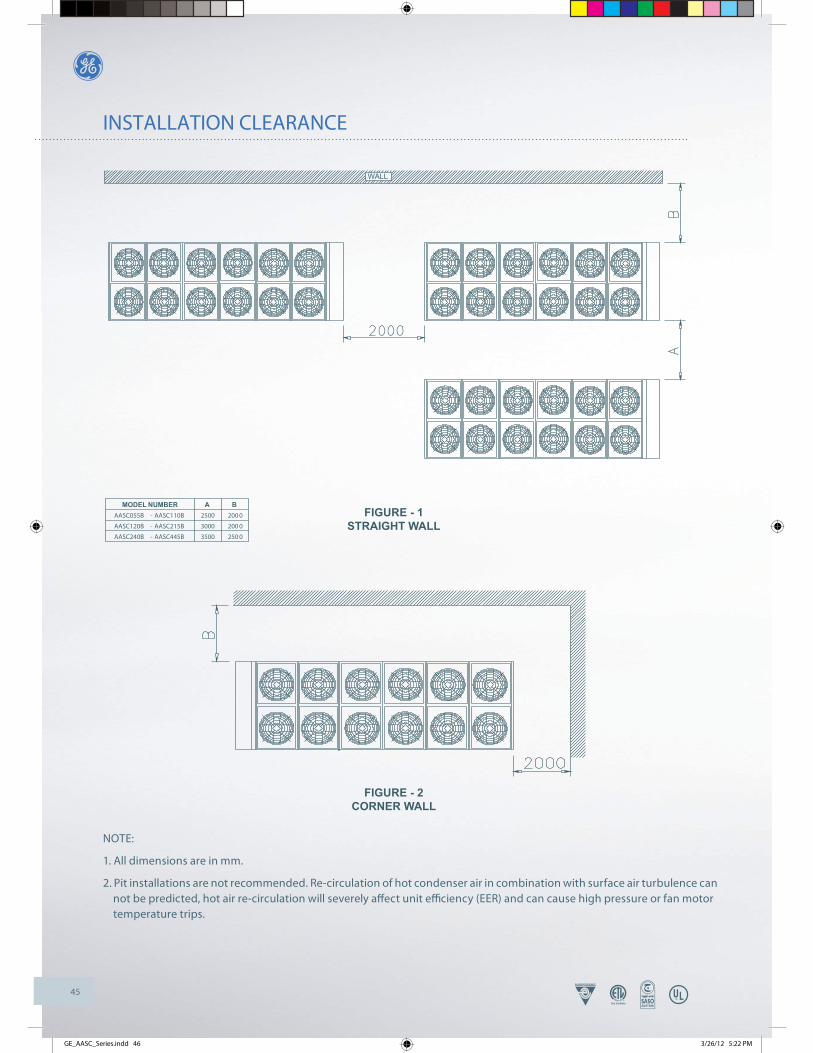
45
NOTE:
1. All dimensions are in mm.
2. Pit installations are not recommended. Re-circulation of hot condenser air in combination with surface air turbulence can not be predicted, hot air re-circulation will severely aff ect unit effi ciency (EER) and can cause high pressure or fan motor temperature trips.
INSTALLATION CLEARANCE
WALL
FIGURE - 2CORNER WALL
FIGURE - 1STRAIGHT WALL
MODEL NUMBER A BAASC055B - AASC110B 2500 200 0
AASC120B - AASC215B 3000 200 0
AASC240B - AASC445B 3500 250 0
GE_AASC_Series.indd 46 3/26/12 5:22 PM
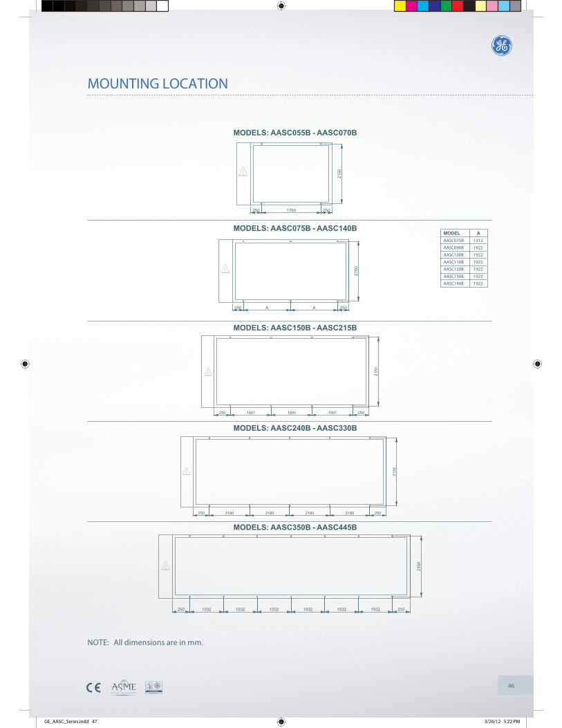
46
NOTE: All dimensions are in mm.
MODELS: AASC075B - AASC140B
MODELS: AASC150B - AASC215B
MODELS: AASC240B - AASC330B
MODELS: AASC350B - AASC445B
MODELS: AASC055B - AASC070B
MODEL AAASC075B 1312
AASC090B 1922
AASC100B 1922
AASC110B 1922
AASC120B 1922
AASC130B 1922
AASC140B 1922
MOUNTING LOCATION
GE_AASC_Series.indd 47 3/26/12 5:22 PM
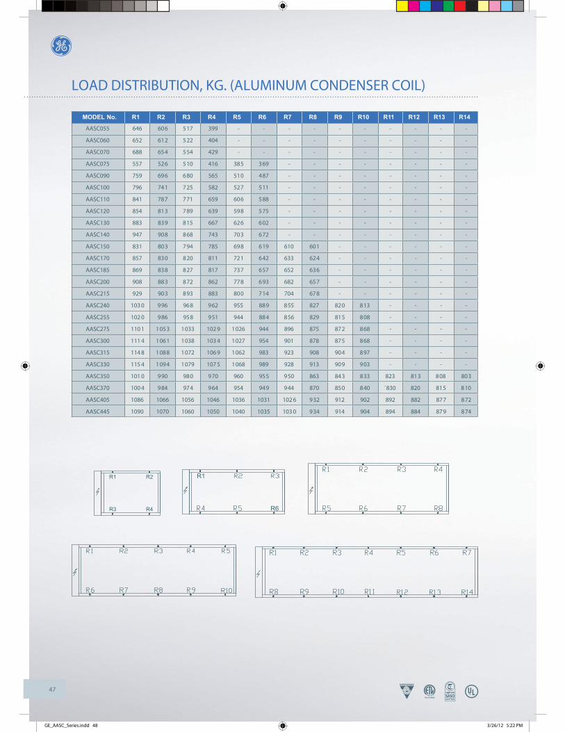
47
LOAD DISTRIBUTION, KG. (ALUMINUM CONDENSER COIL)
MODEL No. R1 R2 R3 R4 R5 R6 R7 R8 R9 R10 R11 R12 R13 R14
AASC055 646 606 517 399 - - - - - - - - - -
AASC060 652 612 522 404 - - - - - - - - - -
AASC070 688 654 554 429 - - - - - - - - - -
AASC075 557 526 510 416 385 369 - - - - - - - -
AASC090 759 696 680 565 510 487 - - - - - - - -
AASC100 796 741 725 582 527 511 - - - - - - - -
AASC110 841 787 771 659 606 588 - - - - - - - -
AASC120 854 813 789 639 598 575 - - - - - - - -
AASC130 883 839 815 667 626 602 - - - - - - - -
AASC140 947 908 868 743 703 672 - - - - - - - -
AASC150 831 803 794 785 698 619 610 601 - - - - - -
AASC170 857 830 820 811 721 642 633 624 - - - - - -
AASC185 869 838 827 817 737 657 652 636 - - - - - -
AASC200 908 883 872 862 778 693 682 657 - - - - - -
AASC215 929 903 893 883 800 714 704 678 - - - - - -
AASC240 103 0 996 968 962 955 889 855 827 820 813 - - - -
AASC255 102 0 986 958 951 944 884 856 829 815 808 - - - -
AASC275 110 1 1053 1033 102 9 1026 944 896 875 872 868 - - - -
AASC300 111 4 1061 1038 103 4 1027 954 901 878 875 868 - - - -
AASC315 114 8 1088 1072 106 9 1062 983 923 908 904 897 - - - -
AASC330 115 4 1094 1079 107 5 1068 989 928 913 909 903 - - - -
AASC350 101 0 990 980 970 960 955 950 863 843 833 823 813 808 803
AASC370 100 4 984 974 964 954 949 944 870 850 840 `830 820 815 810
AASC405 1086 1066 1056 1046 1036 1031 102 6 932 912 902 892 882 877 872
AASC445 1090 1070 1060 1050 1040 1035 103 0 934 914 904 894 884 879 874
R3
R1
R4
R2
R6
R1
GE_AASC_Series.indd 48 3/26/12 5:22 PM

48
LOAD DISTRIBUTION, KG. (COPPER CONDENSER COIL)
R3
R1
R4
R2
R6
R1
MODEL No. R1 R2 R3 R4 R5 R6 R7 R8 R9 R10 R11 R12 R13 R14
AASC055 685 645 555 438 - - - - - - - - - -
AASC060 691 651 560 442 - - - - - - - - - -
AASC070 752 718 618 493 - - - - - - - - - -
AASC075 613 581 566 472 441 425 - - - - - - - -
AASC090 803 740 724 609 554 531 - - - - - - - -
AASC100 852 809 789 643 599 575 - - - - - - - -
AASC110 916 864 845 733 678 663 - - - - - - - -
AASC120 905 864 841 690 649 626 - - - - - - - -
AASC130 968 924 901 752 711 687 - - - - - - - -
AASC140 103 2 993 953 828 789 757 - - - - - - - -
AASC150 888 861 852 843 755 677 668 659 - - - - - -
AASC170 941 913 904 895 805 726 716 707 - - - - - -
AASC185 964 933 923 913 833 753 747 732 - - - - - -
AASC200 100 4 978 968 958 874 788 778 752 - - - - - -
AASC215 103 9 1013 1003 993 910 824 814 788 - - - - - -
AASC240 110 0 1065 1038 103 1 1024 958 924 896 889 883 - - - -
AASC255 108 9 1055 1027 102 0 1017 953 925 898 884 877 - - - -
AASC275 121 6 1168 1148 114 4 1141 1059 1010 990 986 983 - - - -
AASC300 122 8 1175 1153 114 9 1142 1069 1016 993 989 983 - - - -
AASC315 1280 1220 1205 1201 1194 1115 105 5 1040 103 6 1029 - - - -
AASC330 1286 1226 1211 1207 1200 1121 106 0 1045 104 2 1035 - - - -
AASC350 1105 1085 1075 1065 1055 1050 104 5 959 939 929 919 909 904 899
AASC370 1114 1094 1084 1074 1064 1059 105 4 979 959 949 939 929 924 919
AASC405 1212 1192 1182 1172 1162 1157 115 2 1058 103 8 1028 1018 1008 1003 998
AASC445 1216 1196 1186 1176 1166 1161 115 6 1060 104 0 1030 1020 1010 1005 100 0
GE_AASC_Series.indd 49 3/26/12 5:22 PM

Middle East Air Conditioners Co. Ltd.
Middle East Air Conditioners Co. Ltd.P.O. Box 14346 Dammam 31424 KSA
Kingdom of Saudi Arabia| Tel: +966 3 847 2688 Fax: +966 3 847 2931
GE_AASC_Series.indd 50 3/26/12 5:22 PM
Top Related