


Languages
Pages
Legal


Page 1
Textmasterformat, Disclaimer
Author / Department HC XX
Workshop Nasional AFMIDPW AFMI Jawa Tengah
Semarang, 4 – 5 Mei 2017
General Discussion :
Performing QA – QC for CT Scan
Restricted © Siemens Healthcare GmbH, 2016
Page 2
Textmasterformat, Disclaimer
Author / Department HC XX
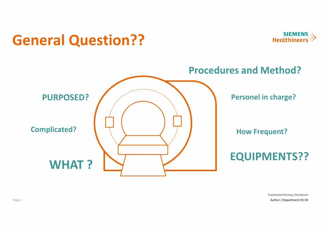
General Question??
EQUIPMENTS??WHAT ?
PURPOSED? Personel in charge?
Complicated?
Procedures and Method?
How Frequent?

Page 3
Textmasterformat, Disclaimer
Author / Department HC XX
What is QA Procedures?
[WORLD HEALTH ORGANIZATION; Quality Assurance in Diagnostic Radiology, WHO, Geneva .1982]
High Quality Image
AdequateDiagnostics
Lowest Cost
LeastPossibleExposure
Quality Assurance

Page 4
Textmasterformat, Disclaimer
Author / Department HC XX
What is QA Procedures?
Quality assurance is a comprehensive concept that comprises all of the oversight and management
practices developed by the CT imaging team led by the supervising physician to ensure that :
1. Every imaging procedure is necessary and appropriate to the clinical problem at hand
2. The combination of acquisition parameters used for each exam is appropriate to address the clinical
question
3. The images generated contain information critical to the solution of that problem
4. The recorded information is correctly interpreted and made available in a timely fashion to the
patient’s physician
5. The examination results in the lowest possible risk to the patient and is consistent with Objective 2
(above)
[ American College of Radiology ; 2012]
Page 5
Textmasterformat, Disclaimer
Author / Department HC XX
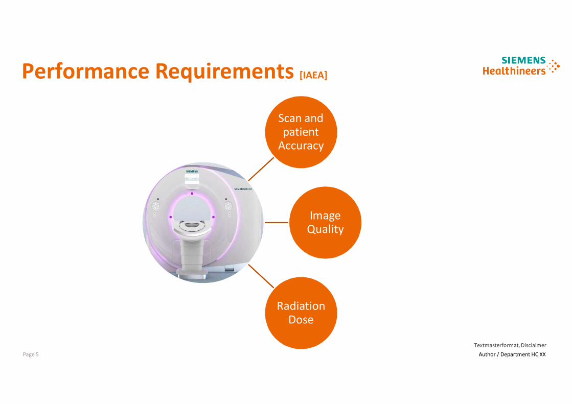
Scan andpatient
Accuracy
ImageQuality
RadiationDose
Performance Requirements [IAEA]
Page 6
Textmasterformat, Disclaimer
Author / Department HC XX
What is QC Procedures?
Bagian dari program QA yang meliputi teknik monitoring dan pemeliharaan alat serta
sistem radiologi
[Jeffrey Papp; Quality Management in the Imaging Sciences Fourth Edition.2013]
Page 7
Textmasterformat, Disclaimer
Author / Department HC XX
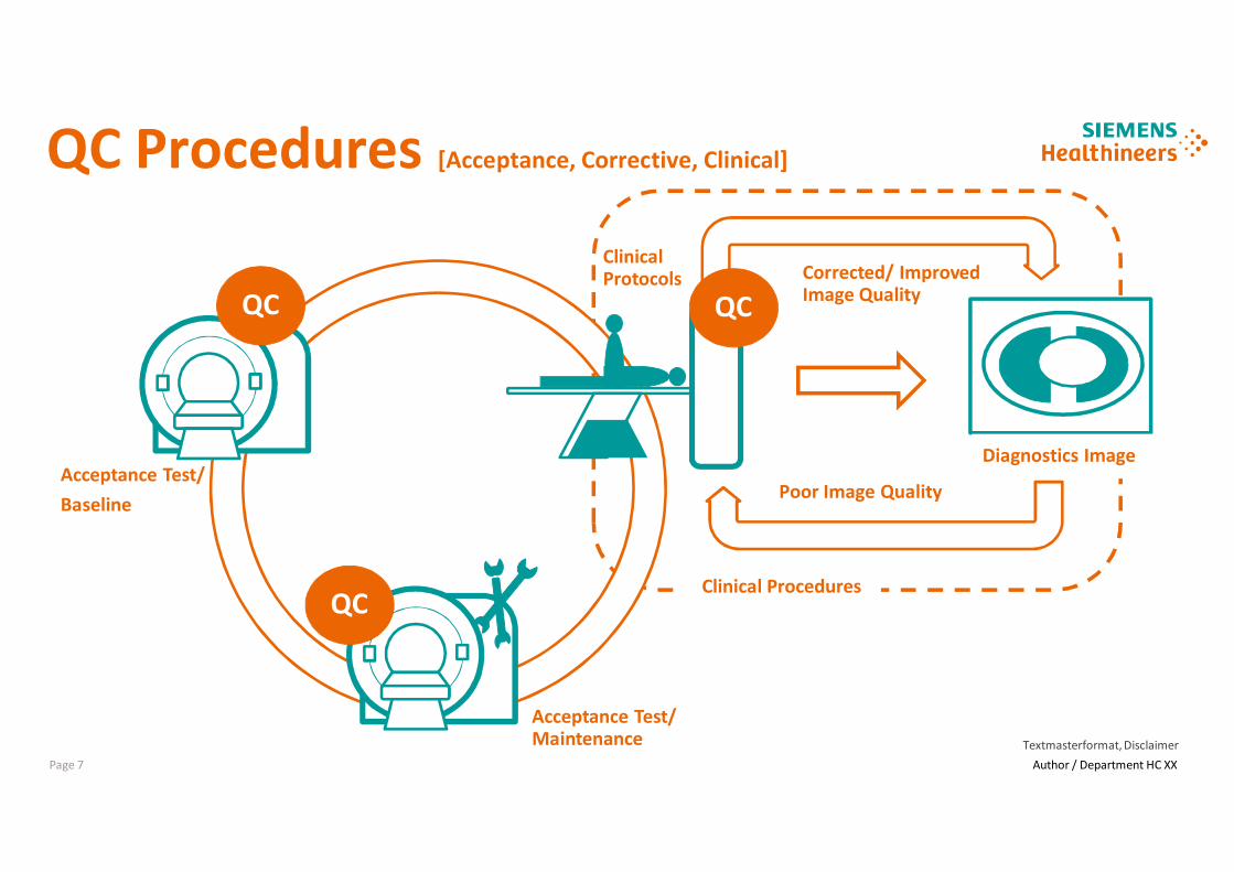
QC Procedures [Acceptance, Corrective, Clinical]
Acceptance Test/
Baseline
Acceptance Test/Maintenance
ClinicalProtocols
Diagnostics Image
Poor Image Quality
Corrected/ ImprovedImage QualityQC
QC
QC
Clinical Procedures

Page 8
Textmasterformat, Disclaimer
Author / Department HC XX
Purposed QC Procedures [Base Line]
Base Line
Tolerance
Tolerance
Corrective
Corrective
Results
Me
asu
rem
en
t
Time/ Period

Page 9
Textmasterformat, Disclaimer
Author / Department HC XX
Personel In Charge QA- QC?
QA – QC
PROGRAMS
Registrant/ Licensee
Radiologist
Technologist/ Radiographer
Medical Physicist

Page 10
Textmasterformat, Disclaimer
Author / Department HC XX
Personel In Charge QA- QC?
REGISTRANT / LICENSEE
1. Ensure that all regulatory and/or licensing requirements are met
2. Ensure that all radiologists, radiographers, medical physicists and other personnel who work at the
facility are appropriately qualified and trained and meet all continuing education and experience
requirements
3. Ensure that a QA programs is in place that encompasses all aspects of the imaging process, it may
be delegated into appropriate staff which has qualification and experiences.
[Quality Assurance Programme for Computed Tomography: Diagnostic and Therapy Applications IAEA]

Page 11
Textmasterformat, Disclaimer
Author / Department HC XX
Personel In Charge QA- QC?
RADIOLOGIST
1. Ensuring that medical physicists and radiographers have adequate training and continuous
education courses in CT & Ensuring that all equipment is appropriately maintained
2. Motivating, supervising and managing all aspects related to the QA programme in the area of CT
3. Providing an orientation programme for radiographers based on a carefully established procedures
manual
4. Designating a single radiographer to be the primary QC radiographer to perform the prescribed QC
tests and oversee those that have been delegated to other individuals
[Quality Assurance Programme for Computed Tomography: Diagnostic and Therapy Applications IAEA]

Page 12
Textmasterformat, Disclaimer
Author / Department HC XX
Personel In Charge QA- QC?
RADIOLOGIST
5. Ensuring availability of the equipment and the necessary materials for the implementation of the
QC tests
6. Arranging staffing and scheduling so that adequate time is available to carry out the QC tests and to
record and interpret the results
7. Ensuring that a medical physicist is available to oversee the equipment related QC programme and
to perform the medical physicist’s tests
[Quality Assurance Programme for Computed Tomography: Diagnostic and Therapy Applications IAEA]

Page 13
Textmasterformat, Disclaimer
Author / Department HC XX
Personel In Charge QA- QC?
RADIOLOGIST
8. Reviewing the radiographer’s test results at least every 3 months, or more frequently if consistency
has not yet been achieved, and reviewing the medical physicist’s test results annually, or more
frequently as needed
9. Designating an individual to oversee the radiation protection programme for employees, patients
and other individuals in the surrounding area
10. Ensuring that records of employee qualifications, mammography technique and procedures,
infection control procedures, QC, safety and protection are properly maintained and updated in the
CT QC procedures manual
11. Providing feedback continually, both positive and negative, to radiographers on image quality and
QC procedures
[Quality Assurance Programme for Computed Tomography: Diagnostic and Therapy Applications IAEA]
Page 14
Textmasterformat, Disclaimer
Author / Department HC XX
Personel In Charge QA- QC?
RADIOGRAPHER
1. Ensuring that the appropriate protocol and technique factors are used for the requested
examination
2. Ensuring that the QC tests are performed, interpreted and recorded appropriately. This is best
achieved when one radiographer assumes overall responsibility for QC matters and is able to train
others to assist in QC activities.
3. Recording imaging problems
4. Undertaking additional continuous education courses.
[Quality Assurance Programme for Computed Tomography: Diagnostic and Therapy Applications IAEA]
Page 15
Textmasterformat, Disclaimer
Author / Department HC XX
Personel In Charge QA- QC?
MEDICAL PHYSICIST
1. Advising the facility on CT image quality and on radiation protection of the patient, staff and
members of the public
2. Advising the facility on acquisition, installation and shielding for CT
3. Conducting tests to ensure the safety and proper performance of equipment used in CT. These
include acceptance, commissioning and routine QC tests
4. Advising the radiologist and radiographer on optimization
5. Providing oversight and advice to the radiographer who carries out the radiographer’s component
of the QC programme.
[Quality Assurance Programme for Computed Tomography: Diagnostic and Therapy Applications IAEA]

Page 16
Textmasterformat, Disclaimer
Author / Department HC XX
Quality Control Ct Scan
Equipments

Page 17
Textmasterformat, Disclaimer
Author / Department HC XX
Unrestricted © Siemens Healthcare GmbH, 2016
Alat Ukur Radiasi dan
Phantom Dosimetry
Phantom Image Quality
/ Performance Phantom
QC Equipments
Analysis Software

Page 18
Textmasterformat, Disclaimer
Author / Department HC XX
Unrestricted © Siemens Healthcare GmbH, 2016
FDA Recommendations
• Contrast Scale
• Noise
• Tomographic Thickness
• Spatial Resolution (High – Low
Contrast)
• CT Number (reverence material)
Manufactures Phantom
Unrestricted © Siemens Healthcare GmbH, 2016

Page 19
Textmasterformat, Disclaimer
Author / Department HC XX
Unrestricted © Siemens Healthcare GmbH, 2016
QC Protocols :
• CT Slice position
• Slice thickness
• CT number homogeneity
• Noise
• Water CT number
• MTF
• Table positioning
“Siemens” Standard QC Phantom

Page 20
Textmasterformat, Disclaimer
Author / Department HC XX
Unrestricted © Siemens Healthcare GmbH, 2016
QC Protocols :
• Slice position
• Slice thickness
• Spatial resolution
• Low contrast
• Noise
• Water CT number
“General Electric” Standard QC Phantom
Page 21
Textmasterformat, Disclaimer
Author / Department HC XX
Unrestricted © Siemens Healthcare GmbH, 2016
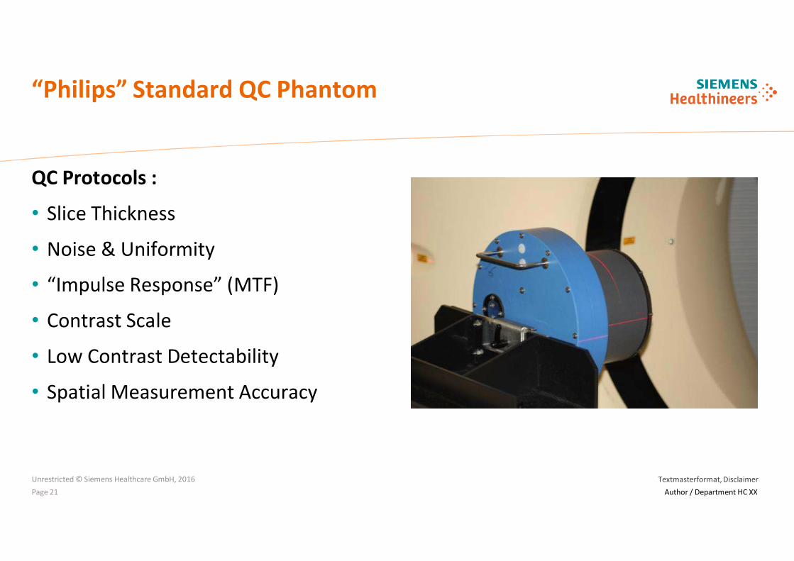
QC Protocols :
• Slice Thickness
• Noise & Uniformity
• “Impulse Response” (MTF)
• Contrast Scale
• Low Contrast Detectability
• Spatial Measurement Accuracy
“Philips” Standard QC Phantom

Page 22
Textmasterformat, Disclaimer
Author / Department HC XX
Unrestricted © Siemens Healthcare GmbH, 2016
QC Protocols :
• Slice Thickness
• Noise & Uniformity
• “Impulse Response” (MTF)
• Contrast Scale
• Low Contrast Detectability
• Spatial Measurement Accuracy
“Toshiba” Standard QC Phantom

Page 23
Textmasterformat, Disclaimer
Author / Department HC XX
Quality Control CT Scan
ACR Quality Control Manual ; 2012
Unrestricted © Siemens Healthcare GmbH, 2016
Procedures andMethods

Page 24
Textmasterformat, Disclaimer
Author / Department HC XX
• CT Number Accuracy
• Artifact Evaluation
• CT Number Uniformity
• Image Noise
• Visual Inspection
• Hard Copy
QA & QC Procedures for Medical Physicist
Unrestricted © Siemens Healthcare GmbH, 2016
• Visual Inspection & Clinical Protocols Review
• Scout Prescription and Alignment Light Accuracy
• Image Thickness – Axial Mode & Sequence
Mode
• Table Travel Accuracy
• Radiation Beam Width
• Dosimetery
• Hard Copy
• Low-Contrast Performance
Daily/ WeeklyMonthly/ Anually
QC

Page 25
Textmasterformat, Disclaimer
Author / Department HC XX
Objectives :
• Ensure that the CT scanner and adjacent areas are safe.
• Ensure that a selection of clinical protocols appropriately
utilizes the scanner features
• Ensure that these protocols obtain the diagnostic image
quality required
Frequency :
• Acceptance test, Annually or after relevant services
Equipments :
• Visual programs and review check list
• QC Charts and Log
• Written Safety procedures
Visual Inspectionand Review Clinical Protocol
Unrestricted © Siemens Healthcare GmbH, 2016
Page 26
Textmasterformat, Disclaimer
Author / Department HC XX
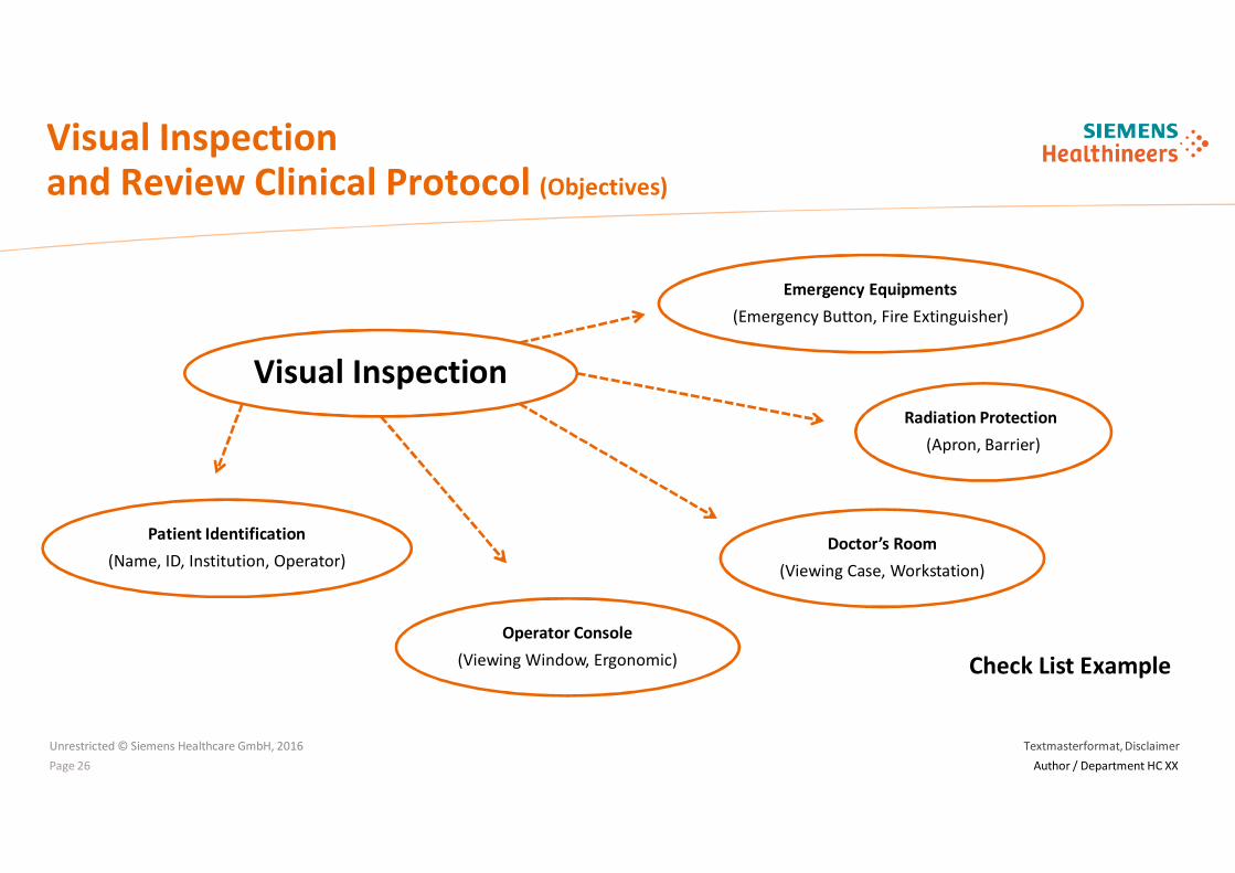
Visual Inspectionand Review Clinical Protocol (Objectives)
Unrestricted © Siemens Healthcare GmbH, 2016
Visual Inspection
Patient Identification
(Name, ID, Institution, Operator)Doctor’s Room
(Viewing Case, Workstation)
Operator Console
(Viewing Window, Ergonomic)
Radiation Protection
(Apron, Barrier)
Emergency Equipments
(Emergency Button, Fire Extinguisher)
Check List Example

Page 27
Textmasterformat, Disclaimer
Author / Department HC XX
Visual Inspectionand Review Clinical Protocol (Objectives)
Unrestricted © Siemens Healthcare GmbH, 2016
Clinical Protocols
Dose Reduction Methods
(Iterative Reconstruction, Dose Modulation)
Acquisition and Reconstruction Parameters
(kV, mA, Collimation, Pitch, Reconstruction Slice )
Review of Clinical Protocols
(Adult/ Pediatric, Head/ Abdomen, HR Thorax)

Page 28
Textmasterformat, Disclaimer
Author / Department HC XX
Detector Configuration and Collimation :
• The largest value of detector configuration or beam collimation available for the scan should be
used whenever practical, as this improves dose efficiency.
Acquisition and Reconstruction Factors :
• Lower kV settings should be considered for pediatric scans as well as those scans that use
intravenous or oral contrast.
• High-Resolution Chest (HRC) protocol should incorporate a sharp reconstruction kernel or filter.
Clinical Dose :
• Doses should be as low as necessary to accomplish the diagnostic task.
• Develop radiation dose thresholds during any new CT protocol design.
Recommendation Regarding Clinical Protocols [AAPM]
Unrestricted © Siemens Healthcare GmbH, 2016

Page 29
Textmasterformat, Disclaimer
Author / Department HC XX
Objectives :
• To verify that the incorporated alignment lights correctly
indicate the scan position and that the scout image
prescription correctly identifies the scan position
Frequency :
• Acceptance test, Annually or after relevant services
Equipments :
• Phantom that incorporates externally visible radiopaque
fiducial markers or an image-center indication
Criteria (IAEA) :
• Acceptable ± 5mm, Achievable ± 1 mm (Beam Alignment)
• Acceptable ± 2mm, Achievable ± 1 mm (Scout Accuracy)
Scout and Alignment Light Accuracy
Unrestricted © Siemens Healthcare GmbH, 2016

Page 30
Textmasterformat, Disclaimer
Author / Department HC XX
Test Procedure : (Beam Alignment)
• Using the alignment lights, carefully position the phantom to
the radiopaque markers/ Image center Indication in all 3
orthogonal planes.
• Zero the table location indication.
• Scan the phantom in axial mode using a reconstructed scan
width less than 2 mm or as thin as the scanner can produce
in axial mode at the zero position.
• Use a technique appropriate to the phantom to allow
accurate visualization of the fiducial markers; for most
phantoms, the adult abdomen technique works well.
Unrestricted © Siemens Healthcare GmbH, 2016
Scout and Alignment Light Accuracy

Page 31
Textmasterformat, Disclaimer
Author / Department HC XX
Test Procedure : (Light Accuracy)
• Scan the entire phantom in scout mode.
• Magnify the image, if possible, and position a single slice at
the location of the radiopaque fiducial markers.
• Perform an axial scan using a reconstructed scan width less
than 2 mm or as thin as the scanner can produce in axial
mode.
Unrestricted © Siemens Healthcare GmbH, 2016
Scout and Alignment Light Accuracy

Page 32
Textmasterformat, Disclaimer
Author / Department HC XX
Analysis : (Light Accuracy)
• Scan the entire phantom in scout mode.
• Magnify the image, if possible, and position a single slice at
the location of the radiopaque fiducial markers.
• Perform an axial scan using a reconstructed scan width less
than 2 mm or as thin as the scanner can produce in axial
mode.
Unrestricted © Siemens Healthcare GmbH, 2016
Scout and Alignment Light Accuracy

Page 33
Textmasterformat, Disclaimer
Author / Department HC XX
Objectives :
• To ensure that the reconstructed imaged slice width is similar
to that selected on the CT scanner console
Frequency :
• Acceptance test, Annually or after relevant services
Equipments :
• A phantom with internal targets that allow the determination
of reconstructed image thickness
Criteria (IAEA) :
Image Thickness
Unrestricted © Siemens Healthcare GmbH, 2016
Nominal Slice (mm) Acceptable
≤ 1 mm < nominal + 0.5 mm
>1 mm and ≤ 2 mm ± 50%
>2 mm ± 1 mm
Page 34
Textmasterformat, Disclaimer
Author / Department HC XX
Test Procedures : (Sequence Mode)
• Align the axial z sensitivity test device so that its axis coincides
with the axis of rotation of the CT scanner with the image
centred in the FOV.
• Perform an SPR to confirm acceptable alignment and to
define the tomographic plane.
• Select a scan protocol.
• Scan the test object as required.
• Repeat for all other selected scan protocols.
Image Thickness
Unrestricted © Siemens Healthcare GmbH, 2016

Page 35
Textmasterformat, Disclaimer
Author / Department HC XX
Test Procedures : (Helical Mode)
• Place the helical z sensitivity test object on the CT couch or
secure it on a stand so that it is centred in the FOV and
aligned such that the metal foil insert is parallel to the
tomographic plane.
• Perform an SPR and define the scanned volume for helical
scanning to ensure the metal foil is fully imaged.
• Select a scan protocol.
• Scan the test object.
• Reconstruct images at intervals of approximately one tenth of
the nominal imaged slice width.
Image Thickness
Unrestricted © Siemens Healthcare GmbH, 2016

Page 36
Textmasterformat, Disclaimer
Author / Department HC XX
Unrestricted © Siemens Healthcare GmbH, 2016
Data Analysis :
• Place an ROI over the central portion of each reconstructed
image corresponding to the position of the metal disc insert
and measure the average CT number in it.
• Plot the measured values of the CT number versus image
position (distance in the z axis direction) in chart.
• Determine CTmax and CTb.
• Determine the FWHM by calculating the distance between
the two points corresponding to the CThalf values.
• Simple linear interpolation may be used to obtain this
distance more accurately. This distance represents the
imaged slice width .
Image Thickness
( )b
bMaxhalf CT
CTCTCT +
-=
2
0
5
10
15
20
25
30
FWHM

Page 37
Textmasterformat, Disclaimer
Author / Department HC XX
Unrestricted © Siemens Healthcare GmbH, 2016
Image Thickness
( )b
bMaxhalf CT
CTCTCT +
-=
2
0
10
20
30
40
50
60
70
80
FWHM
Slice Width

Page 38
Textmasterformat, Disclaimer
Author / Department HC XX
Objectives :
• To verify that the patient table translates as indicated
Frequency :
• Acceptance test, Annually or after relevant services
Equipments :
• A phantom with 2 sets of external fiducial markers of known
separation
Criteria (IAEA) :
• The table translation accuracy and return to a fixed position
should be accurate to within 2 mm
Table Travel Accuracy
Unrestricted © Siemens Healthcare GmbH, 2016

Page 39
Textmasterformat, Disclaimer
Author / Department HC XX
Test Procedures :
• If possible, add weight to the tabletop to simulate the weight
of an average patient.
• Using the alignment light, carefully position the phantom
such that the first set of fiducial markers is in the axial plane.
• Zero the table position indication.
• Move the table to the second set of external fiducial
markers.
• Record the table position.
• Translate the table to full extension and return to the first set
of fiducial markers.
• Record the new table position.
Table Travel Accuracy
Unrestricted © Siemens Healthcare GmbH, 2016

Page 40
Textmasterformat, Disclaimer
Author / Department HC XX
Unrestricted © Siemens Healthcare GmbH, 2016
Data Analysis :
• Compare the distance between the fiducial markers as
determined by the table travel to the known distance.
• Compare the first fiducial marker table position to the new
position recorded after the table extension and return.
Criteria (IAEA) :
• The table translation accuracy and return to a fixed position
should be accurate to within 2 mm
Table Travel Accuracy

Page 41
Textmasterformat, Disclaimer
Author / Department HC XX
Objectives :
• To measure the radiation beam width and to assess its
relationship to the nominal collimated beam width
• To determine the extent of over-beaming
Frequency :
• Acceptance test, Commisioning, Annualy or after relevant
services
Equipments :
• External radiation detector (CR Plate, Gafchromic Film, TLD
array)
• Atenuator Plate
Criteria (IAEA) :
• Within 3mm or 30% of Applied Colimator
Radiation Beam Width
Unrestricted © Siemens Healthcare GmbH, 2016

Page 42
Textmasterformat, Disclaimer
Author / Department HC XX
Test Procedures :
• Place film on a flat foam block to minimize scatter on the film.
• Raise the couch so that the film surface is on the isocentre of
the scanner.
• Mark the isocentre of the film.
• Scan the film in axial mode for one collimation setting using a
set kV and mAs as required to give the film a density that is
clearly below the film maximum density.
• Repeat for all other selected scan protocols.
Radiation Beam Width
Unrestricted © Siemens Healthcare GmbH, 2016

Page 43
Textmasterformat, Disclaimer
Author / Department HC XX
Data Analysis :
• Plot the profile of the density of the exposed film using a film
scanning device
• Defines the FWHM value for the film, apply the density value
for the FWHM to each of the beams plotted to determine the
X ray beam width.
Radiation Beam Width
Unrestricted © Siemens Healthcare GmbH, 2016

Page 44
Textmasterformat, Disclaimer
Author / Department HC XX
Unrestricted © Siemens Healthcare GmbH, 2016
Radiation Beam Width
Criteria (IAEA) :
• Within 3mm or 30% of Applied Colimator
0
5
10
15
20
25
30
Density
FWHM
Slice Width

Page 45
Textmasterformat, Disclaimer
Author / Department HC XX
Objectives :
• To verify that the low-contrast performance of clinical
protocols is adequate for diagnosis
Frequency :
• Acceptance test, Annualy or after relevant services
Equipments :
• A phantom that incorporates low-contrast targets of known
contrast
Low Contrast Performance
Unrestricted © Siemens Healthcare GmbH, 2016

Page 46
Textmasterformat, Disclaimer
Author / Department HC XX
Test Procedures :
• Align the phantom.
• Perform clinical scans covering the low-contrast section of
the phantom (No Dose Modulation).
• At a minimum, the scans performed should include the
following:
• Adult head (average)
• Pediatric head (1 year old)
• Adult abdomen (70 kg)
• Pediatric abdomen (5 years old; 40-50 lb, approx. 20 kg)
Low Contrast Performance
Unrestricted © Siemens Healthcare GmbH, 2016
Page 47
Textmasterformat, Disclaimer
Author / Department HC XX
Data Analysis : (Visual Analysis)
• View each series and determine the image that provides the
best low-contrast performance.
• Adjust the window width/level to optimize visibility of the
low-contrast targets.
• Record the size and/or contrast of the barely visualized
target.
Low Contrast Performance
Unrestricted © Siemens Healthcare GmbH, 2016

Page 48
Textmasterformat, Disclaimer
Author / Department HC XX
Data Analysis : (Numeric Analysis)
• View each series and determine the image that provides the
best low-contrast performance .
• Place ROI to measure HU number of the target material and
structure adjacent the target
• Calculate CNR from largest representative target and
adjacent background
Low Contrast Performance
Unrestricted © Siemens Healthcare GmbH, 2016

Page 49
Textmasterformat, Disclaimer
Author / Department HC XX
Unrestricted © Siemens Healthcare GmbH, 2016
Low Contrast Performance
Scan protocol CNR
Adult Head 1.0
Pediatric Head 1.0
Adult Abdomen 1.0
Pediatric Abdomen 0.5
Criteria :
( )stdev
meanmean
BG
BGTCNR
-=

Page 50
Textmasterformat, Disclaimer
Author / Department HC XX
Objectives :
• To ensure that the spatial resolution of a reconstructed image
complies with manufacture standards.
Frequency :
• Acceptance test, Annualy or after relevant services
Equipments :
• A phantom that incorporates with spatial resolution either for
visual analysis or MTF analysis
Spatial Resolution
Unrestricted © Siemens Healthcare GmbH, 2016

Page 51
Textmasterformat, Disclaimer
Author / Department HC XX
Test Procedures :
• Align the phantom.
• Perform clinical scans covering the low-contrast section of
the phantom (No Dose Modulation).
• At a minimum, the scans performed should include the
following:
• Adult abdomen (average)
• High Resolution Chest
Spatial Resolution
Unrestricted © Siemens Healthcare GmbH, 2016
Page 52
Textmasterformat, Disclaimer
Author / Department HC XX
Data Analysis : (Visual Analysis)
• View each series and determine the image that provides the
best high-contrast target.
• Adjust the window width/level to optimize visibility of the
low-contrast targets.
• Determine and record the highest frequency visible in the
image.
Data Analysis : (Software Analysis)
• Use proper software (some may provide by CT Manufacture)
to create MTF for determine spatial resolution
Spatial Resolution
Unrestricted © Siemens Healthcare GmbH, 2016

Page 53
Textmasterformat, Disclaimer
Author / Department HC XX
Unrestricted © Siemens Healthcare GmbH, 2016
Criteria (IAEA) :
• Within manufacture criteria
Spatial Resolution
Scan protocol Limiting Resolution
Adult Abdomen 6 lp/cm
High-Resolution Chest 8 lp/cm

Page 54
Textmasterformat, Disclaimer
Author / Department HC XX
Objectives :
• To verify that the CT numbers reported by the CT scanner are
acceptably accurate and vary as expected.
Frequency :
• Acceptance test, Annualy or after relevant services
Equipments :
• A phantom that incorporates targets that provide different
known CT number values.
• Phantom provide by manufacture for co-responding test
CT Number Accuracy, Artifacts, Noise and Uniformity
Unrestricted © Siemens Healthcare GmbH, 2016

Page 55
Textmasterformat, Disclaimer
Author / Department HC XX
Test Procedures :
• Align the phantom.
• Perform clinical scans covering the low-contrast section of
the phantom (No Dose Modulation).
• If possible, the scans performed should include the
following:
• Adult Head
• Pediatric Head
• Adult abdomen (average)
• Pediatric Abdomen
CT Number Accuracy, Artifacts, Noise and Uniformity
Unrestricted © Siemens Healthcare GmbH, 2016

Page 56
Textmasterformat, Disclaimer
Author / Department HC XX
Data Analysis : (CT Number Accuracy)
• Select the image most central to the module containing the
CT number accuracy targets.
• Adjust the window width/level to optimize visibility of the
targets.
• Place a circular ROI, approximately 80% of the size of the
target, in each target.
• Record the measured CT number mean for each target
CT Number Accuracy, Artifacts, Noise and Uniformity
Unrestricted © Siemens Healthcare GmbH, 2016

Page 57
Textmasterformat, Disclaimer
Author / Department HC XX
Unrestricted © Siemens Healthcare GmbH, 2016
CT Number Accuracy, Artifacts, Noise and Uniformity
Criteria [IAEA] :
• Acceptable± 5 from baseline value, achievable± 4
(water)
• Acceptable± 10 from baseline value (material)

Page 58
Textmasterformat, Disclaimer
Author / Department HC XX
Data Analysis : (Noise and Uniformity)
• Select image of water phantom (homogen, no air inside).
• Adjust the window width/level to optimize visibility of the
targets.
• Place a circular ROI, at least in 5 position inside the phantom
which represent central and peripheral area of the phantom.
• Record the measured CT number mean for each target ROI
Criteria :
CT Number Accuracy, Artifacts, Noise and Uniformity
Unrestricted © Siemens Healthcare GmbH, 2016
Test Type Acceptable Achievable
Image noise ±25% of the baseline ±10% of the baseline
Uniformity ±10 ±4

Page 59
Textmasterformat, Disclaimer
Author / Department HC XX
Data Analysis : (Artifacts)
• Select image of water phantom (homogen, no air inside).
• Adjust the window width/level to optimize visibility of the
targets.
• Visual interpretation of image to evaluate a possible artifacts
shown
Criteria :
• No visual artefacts shown in the image
CT Number Accuracy, Artifacts, Noise and Uniformity
Unrestricted © Siemens Healthcare GmbH, 2016

Page 60
Textmasterformat, Disclaimer
Author / Department HC XX
Unrestricted © Siemens Healthcare GmbH, 2016
CT Number Accuracy, Artifacts, Noise and Uniformity
Criteria [IAEA] :
• No Artifacts shown in the image
Test Type Acceptable Achievable
Image noise ±25% of the baseline ±10% of the baseline
Uniformity ±10 ±4

Page 61
Textmasterformat, Disclaimer
Author / Department HC XX
Objectives :
• To measure doses for verification of scanner performance and
to allow for calculation of dosimetric quantities relevant to
patient exam estimates.
Frequency :
• Acceptance test, Annualy or after relevant services
Equipments :
• Calibrated electrometer and CTDI pencil ionization chamber
(10- or 15-cm long)
• 16-cm (head) CTDI dosimetry phantom
• 32-cm (adult body) CTDI dosimetry phantom
Dosimetry
Unrestricted © Siemens Healthcare GmbH, 2016

Page 62
Textmasterformat, Disclaimer
Author / Department HC XX
Dosimetry

Page 63
Textmasterformat, Disclaimer
Author / Department HC XX
CTDIw dan CTDIvol
centralPeripheral
w CTDICTDICTDI 1001003
1
3
2×+×=
x
y
z
Detector÷øöç
èæ
=
ncollimatiototalscanperfeed
wvol
CTDICTDI
pitch
wvol
CTDICTDI =
Multi Slice/ VolumetricScan

Page 64
Textmasterformat, Disclaimer
Author / Department HC XX
Unrestricted © Siemens Healthcare GmbH, 2016
Criteria :
• Dose Calculation in Air : Output at every kVp ±5%
from baseline
• CTDIvol for clinical protocols : Less than Dose Reference
Level
• Verify scanner CTDIvol :±10%
Dosimetry

Page 65
Textmasterformat, Disclaimer
Author / Department HC XX
Unrestricted © Siemens Healthcare GmbH, 2016
Semarang, 4 – 5 May 2017
Thanks all
For Your Kind
Attention
Top Related