


Languages
Pages
Legal


GDS200/250
GROUND DRIVE
MULTI-SPREADER
USER MANUAL
WM2-GDS200

2
INDEX
Section:
Description: Page No:
1 Introduction 3
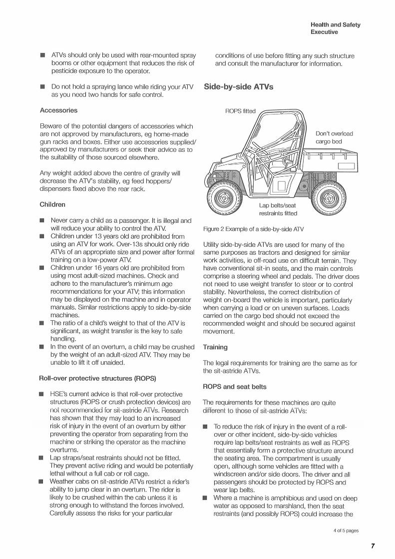
HSE Information Sheet 4-8
2 In the interest of safety: DO NOT 9
3 In the interest of safety: DO 9
4 Instructions / Warning Decals 10
5 Lifting 11
6 Operating Instructions and Adjustments 11
6.1 Attaching to the Towing Vehicle 11
6.2 Operating principles 12
6.3 Calibration 13
6.4 Spreader Pattern Adjustment 14
6.5 Spreader Settings Chart 15
7 Maintenance / Service 16
7.1 Daily 16
8 Specification 22
9 Parts Information 23-28
10 Logic Manufacturing Product Owner 29
LOGIC: Declaration of conformity 30
7.2 Weekly 17
7.3 End of Season 18
7.4 Drive Belt Replacement Procedure 19
7.4.1 Main Drive ‘V’ Belt 19
7.4.2 Spinner Drive Belt 20-21
7.4.3 Tonneau Cover Kit Fitting 21
SERIAL NO: ------------------------------------------------- Date of purchase: -------------------------------------------------
IMPORTANT INFORMATION: Fill in immediately. Use when ordering replacement spare parts or additional optional extras

3
INTRODUCTION 1
With the purchase of your LOGIC GROUND DRIVE MULTI – SPREADER you have made an excellent choice.
This machine should give first class service for a long time, if used correctly and maintained as described in this manual.
The flexibility of ground drive allows a wide choice of towing vehicle and spreading width variation will suit many situations.
Design and construction is of high quality, with anti – corrosive components used throughout.
Various options such as wheels, mudguards, couplings, flashing beacon and road lights are available to complete whatever specification is required.
If after reading this manual there are any queries, please get in touch, we will be pleased to help.
NORTH & EXPORT SOUTH LOGIC MANUFACTURING LTD LOGIC MH LTD - New Whiteway Works, Foundry Industrial Estate Fossecross Industrial Estate Bridge End, Hexham Chedworth. Cheltenham Northumberland NE46 4JL Gloucestershire GL54 4NW Tel: 01434 606661 Fax: 01434 608143 Tel: 01285 720930 Fax:01285 720840 E-mail: [email protected] E-mail: [email protected] www.LogicToday.co.uk www.LogicToday.co.uk

4

5

6
7

8

9
This symbol means WARNING or CAUTION. Personal safety or damage will be at risk if these instructions are ignored. Most accidents are caused by neglect or carelessness. Avoid needless accidents by following the safety precautions listed below.
2 IN THE INTEREST OF SAFETY: DO NOT
DO NOT – Operate the spreader unless you have read this entire manual.
DO NOT – Operate the spreader if any parts are defective, replace any defective parts before use.
DO NOT – Touch moving parts.
DO NOT – Exceed sensible towing speeds. (Max 30mph)
3 IN THE INTEREST OF SAFETY: DO
DO – Follow all manufacturer’s guidelines.
DO – Attach the spreader to a suitable towing vehicle.
DO – Follow all manufacturer’s service instructions.
DO – Be aware of travelling conditions – Do not exceed sensible speeds.
DO – Follow all safety instructions in this manual.
DO – Make sure all persons are a safe distance when operating the spreader, especially when operating in areas used by the public.
DO – Make sure all nuts bolts and fittings are secure before using and check at regular intervals during operation.
DO – Avoid excessively steep slopes or adverse ground conditions.
!!!!

10
4 INSTRUCTIONS / WARNING DECALS
The above decals should be located on your spreader. If any of the above decals are not located on your spreader or are damaged in any way contact Logic for some
Replacements decals before use.
!!!!

11
LIFTING POINTS 5
The GDS has three lifting point positions, always lift from the lifting points clearly marked on the GDS.
• Use lifting slings, never lifting chains.
• To ensure safe lifting always lift the spreader using lifting slings that comply with BS EN1492-1.
• Never lift the GDS200/250 when the hopper is loaded.
• Always check lifting load limits before lifting
• Lifting equipment manufacturers guidelines must be followed at all times.
• Position lifting slings where you see this symbol:
• Ensure pedestrians are clear from danger.
• Protect any paint work to prevent straps causing damage
NB: Refer to the manufactures weight plate located on the spreader for unladen lifting weight
OPERATING INSTRUCTIONS AND ADJUSTMENTS 6
The spreader is designed to give safe and dependable service if operated according to instructions and intended use.
Read and understand this manual before operating the unit, as failure to do so could result in personal injury or equipment damage.
INITIAL CHECK
Make sure that all nuts, bolts and fittings are securely fixed, and that all packaging materials e.g. wire bands, tape etc have been removed.
6.1 ATTACHING TO THE TOWING VEHICLE
The Logic Multi – Spreader can be towed by a wide range of suitable vehicles from the largest of ATVs to tractors, vans, pickups and 4 X 4s etc.
Standard coupling is by swivel ball hitch although options include clevis or ring for tractor type hitches.
The Multi-Spreader should be as level as possible during operation. The coupling housing can be positioned above or below the drawbar to achieve this. If other measures are required, please contact the Logic office for advice.
Attach the wire cable (secondary coupling, for statutory safeguard) to a point on the towing bracket, a suggested position would be over the ball, then attach the swivel coupling to the ball. Ensure the coupling is properly seated and check for any obstructions that may effect full movement.

12
6.2 OPERATING PRINCIPLES
The following procedures should enable operators to get the best results from this machine in most circumstances.
1. Before loading, check that the belt drive is disengaged and the feed gate is closed.
2. It is essential that the towing vehicle weight restrictions (if any) are taken into account. (See manufactures plate on GDS for loading limits)
3. Never overload the hopper and take particular note of the tyres for signs of wear or deflation.
Check tyre pressure regularly, lug tread tyres should be 26 psi.
Road tyres should be 45 Psi.
4. The hopper should be filled through the loading screen to prevent any foreign bodies entering the discharge mechanism causing damage or blockages. Filling by hand does not take long and should not cause any problems. Filling with a mechanical shovel requires more caution to prevent the agitator bar from being pushed sideways. Fill the hopper slowly and from a central position.
5. Check the drive is still disengaged, and then drive carefully to the operation area at the maximum speed of 30 mph.
6. Set the discharge feed gate to the required opening for the appropriate application rate. See calibration section. NOTE If the load has consolidated after a long journey from the store area, attach the hand lever to the agitator beam and shake vigorously, open the feed gate to maximum for the first 5-10 seconds then re-set the feed gate to the appropriate setting.
7. Check that the offset vanes on the drop chute are set correctly. See calibration guide.
8. Move the engagement lever to the ‘drive’ position. Variations of the engagement lever handle are available to improve the ease of use from the operator’s position.
9. Move off with the towing vehicle to reach the operating speed as quickly and safely as possible.
10. Maintain the correct forward speed as far as possible; in the understanding that speeding up will create a wider spread width, slowing forward speed will reduce the spread width. In many cases a fluctuation in speed will be necessary to cope with road junctions, traffic lights and hazards of various kinds. The unit is small and manoeuvrable enough to go over the treatment area again to fill in any missed pieces.
11. When treating highways with a precautionary application of salt, it is advisable to travel on the nearside of the road with the offset adjustment set to cover the centre area of both carriageways, bearing in mind dry salt will bounce a further distance and an area of 1 metre on the margins of the road will not need treatment as traffic will soon disperse salt particles to the full width of the road.
When spreading onto snow-covered roads, there will be no bounce effect so that a wider spreading width will be required. An appropriate increase in material feed to the spinner could be considered to increase the application rate per square metre.
WHEN SPREADING IS COMPLETE OR WHEN THE HOPPER IS EMPTY IT IS ESSENTIAL THAT THE ENGAGEMENT LEVER IS MOVED TO DISENGAGE.
FAILURE TO DO THIS, ESPECIALLY WHEN TRAVELLING DISTANCES OR AT HIGHER SPEEDS CAN RESULT IN DAMAGE TO THE DISC AND AGITATOR DRIVE SYSTEM.
!!!!

13
6.3 CALIBRATION
The Logic Multi–Spreader is capable of spreading a wide range of flow-able products, the most common being salt, sand and grit.
In most cases the operating principles and calibration are the same, with just one mechanical adjustment for application rate.
All materials will vary slightly, depending on density and moisture, etc, even in the same heap, a range of conditions will be found.
The following steps are intended as a guide only and it is highly recommended that simple test runs are carried out in the filling area before setting out, to check that the spreading quantity and pattern are satisfactory.
The main controlling factor is forward speed, which dictates the spreading width. The application rate will then be controlled by the feed gate setting.
The recommended minimum forward speed is 5 mph (8 kph). This would be used in confined spaces, or where a minimum spreading width is required e.g. a footpath. At this speed the spreading width will be approx. 5’ (1.5 m). Recommended maximum speed is 15 mph (24 kph) which will result in a spreading width of approx. 32’ (10 m) suitable for car parks and roads, etc.
The feed gate setting at the back of the hopper controls the material flow and therefore the application rate (grams per sq metre).
The slide opens from zero to 6.5 (65mm) which should give a wide range of application rates for any situation.
CALIBRATION STAGES
1. Decide what spread width is required in relation to a safe working speed.
As a guide (standard g/box) 5 mph = 1.5m (fast g/box) 5mph = 3m
10 mph = 6m = 10m
15 mph = 10m = 14m
2. Select the feed gate setting to achieve the desired application rate.
This will depend on trials carried out with materials to be spread at the time.
As a guide Setting 2 (cm) at 5 mph (s g/b)= 25 gr/sq m, (f g/b) = 12 gr/sq m
(using salt) Setting 2 (cm) at 10 mph (s g/b)= 5 gr/sq m, (f g/b) = 3 gr/sq m
Setting 4 (cm) at 5 mph (s g/b)= 50 gr/sq m, (f g/b) = 25 gr/sq m
Setting 4 (cm) at 10 mph (s g/b)= 10 gr/sq m, (f g/b) = 6 gr/sq m
Setting 6 (cm) at 5 mph (s g/b)= 80 gr/sq m, (f g/b) = 40 gr/sq m
Setting 6 (cm) at 10 mph (s g/b)= 20 gr/sq m, (f g/b) = 12 gr/sq m
Setting 6 (cm) at 15 mph (s g/b)= 12 gr/sq m, (f g/b) = 7 gr/sq m
(Note - s g/b = standard gearbox, f g/b = fast gearbox).
3. To check the accuracy of the settings, try a few trial runs over a clean area of concrete or road surface, at the correct forward speed. Check the spread width, which may vary due to bouncing material if it is very dry.
Check the application rate by sweeping up 1 square metre and weighing the contents. Alternatively, use a 1m x 1m piece of paper to collect the material. Several passes over the area will provide a more accurate average result.
4. Write down results for future reference.
14
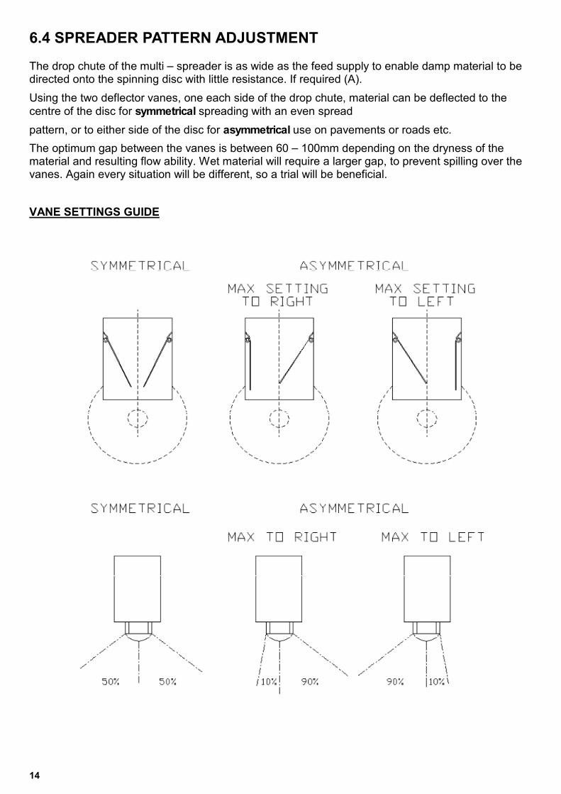
6.4 SPREADER PATTERN ADJUSTMENT
The drop chute of the multi – spreader is as wide as the feed supply to enable damp material to be directed onto the spinning disc with little resistance. If required (A).
Using the two deflector vanes, one each side of the drop chute, material can be deflected to the
centre of the disc for symmetrical spreading with an even spread
pattern, or to either side of the disc for asymmetrical use on pavements or roads etc.
The optimum gap between the vanes is between 60 – 100mm depending on the dryness of the material and resulting flow ability. Wet material will require a larger gap, to prevent spilling over the vanes. Again every situation will be different, so a trial will be beneficial.
VANE SETTINGS GUIDE

15
6.5 SPREADER SETTINGS CHART
MATERIAL TOWING VEHICLE
OPERATING
SPEED (mph)
SPREAD
WIDTH (m)
FEED GATE
SETTING
APPLICATION
RATE (gms/sqm)
(EXAMPLE)
SAND (wet) Kubota Tractor 10 6 4 10
6.6 SPREADER TYRE PRESSURES
TYRE SIZE/MAKE RECOMMENDED
PRESSURE WT950L 7-14 Fieldmax 26 psi
WT950R 7-14 Fieldmax 26 psi
WT750 195/60R14 Camac 45 psi
WT750 195/60R14 Hankook 45 psi
16
Always empty the hopper before any routine work
!!!!
7 MAINTENANCE / SERVICE
7.1 DAILY
1. Check the condition of the tyres and tyre pressure – for lug-tread tyres – 26psi,
road tyres – 45psi.
2. Check wheel nuts are tight – 65 lbs ft torque.
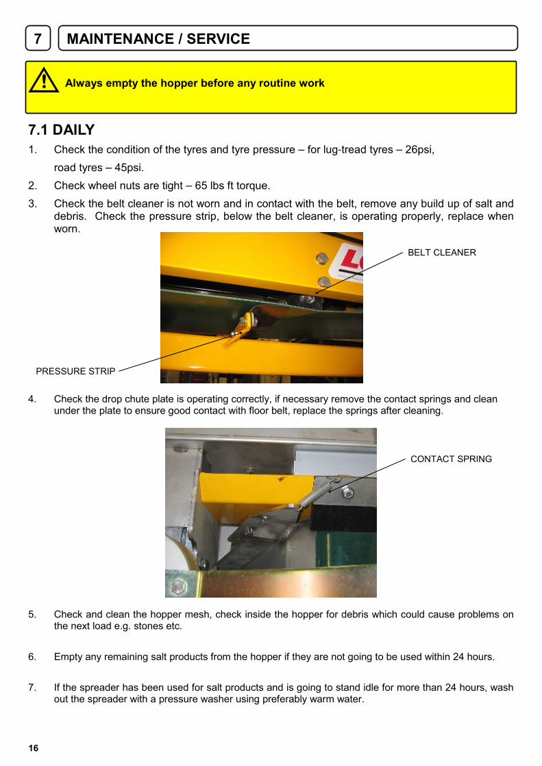
3. Check the belt cleaner is not worn and in contact with the belt, remove any build up of salt and debris. Check the pressure strip, below the belt cleaner, is operating properly, replace when worn.
4. Check the drop chute plate is operating correctly, if necessary remove the contact springs and clean under the plate to ensure good contact with floor belt, replace the springs after cleaning.
5. Check and clean the hopper mesh, check inside the hopper for debris which could cause problems on the next load e.g. stones etc.
6. Empty any remaining salt products from the hopper if they are not going to be used within 24 hours.
7. If the spreader has been used for salt products and is going to stand idle for more than 24 hours, wash out the spreader with a pressure washer using preferably warm water.
BELT CLEANER
PRESSURE STRIP
CONTACT SPRING

17
7.2 WEEKLY
1. Remove the transmission cover and check the condition of all the belts.
2. Check the idling pulley on the main drive belt for dust build up and signs of wear. Check that the lower belt stop on the drive axle is not fouled by any foreign objects or dirt. The gap between the stop and the belt pulley should be approx 6mm (A). If this needs adjusting, remove the stop from the axle and hold in a vice to carefully bend the loop to the correct angle.
3. Check the belt trap at the gearbox end of the drive belt surrounding the outer part of the 3 belt pulley, for signs of miss-alignment or required cleaning, re-adjust if necessary. ( For details of resetting, see page 16.)
4. Check the link belt stud heads are at 90° to the direction of travel.
5. Check the plygene flap on the disc deflector plate surrounding the spreading disc for signs of wear. Replace if necessary.
6. Grease the axle bearings, 2-3 pumps of a grease gun should be sufficient.
7. Check the feed gate adjustment knob for lubrication. Use a metal-free, anti-seize compound
8. Pressure wash the machine especially around the conveyor belt area. Use warm water if possible.
9. Check and lubricate the jack and drawbar coupling with an aerosol penetrating oil.
A

18
7.3 END OF SEASON
1. Check the cam housing on the gearbox drive of the agitator, remove the 4 bolts, dismantle and clean out, check for signs of wear. Replace the lubricating agent. Use Grease-Super lube part no MLU-020 from Logic. Check the other parts of the agitation system.
2. Thoroughly clean the inside of the transmission housing, including all the belts and belt trap on the main drive belt.
3. Release the tension on the floor belt, thoroughly check the condition of the belt top and bottom. Check the condition of the rollers for damage or wear. On the drive roller there is a nylon bearing at each side. The idling roller has no replacement bearing as it is made of bearing material, check for play on both rollers. When re-tensioning the floor belt at the beginning of a season as a guide 10-12mm of thread should be showing from the locknut on the tensioning bolts (factory setting). DO NOT OVER TIGHTEN. All that will happen if the floor belt is not tight will be slippage, over tight could cause belt damage and excessive wear on bearings. Tighten 1mm at a time to overcome any slippage.
4. Check the main drive axle and bearings for signs of wear and replace any suspect bearings.
5. Grease all sliding parts including feed gate, engagement levers and linkages.
6. Check the gearbox output shafts for signs of wear.
NOTE Both gearboxes are maintenance free. They should not be tampered with or taken apart for any reason, unless authorised by Logic.
7. Slacken the bolts securing the drop chute vanes to allow free movement during the lay-off period.
8. Check damage to paint work and repair.
9. Pressure wash thoroughly inside and out using warm water.
10. Store in a dry place if possible.
TENSIONING BOLT
SETTING GUIDE 10-12MM

19
7.4 DRIVE BELT REPLACEMENT PROCEDURE
7.4.1 MAIN DRIVE ‘V’ BELT
1. Disengage the drive mechanism and remove the transmission cover.
2. Jack up the drive side (nearside) of the axle. NOTE place a sturdy piece of wood across the bottom of the chassis cross member for the jack to be positioned under. Support the rest of the spreader to ensure complete stability.
B
MAIN DRIVE
PULLEY
C
D
3. Remove the nearside drive wheel from the axle.
4. Remove the nylon idle pulley (C) from the drive engagement linkage.
5. Remove the drive belt stop bracket (D)
6. Remove the belt trap (A) from the transmission guard.
7. Remove the drive belt (B) from the main drive pulley and axle pulley.
8. Remove the two bolts securing the drive wheel axle bearing. Allow the axle to drop just enough to remove the drive belt.
9. Replace the old belt with a genuine replacement belt from Logic.
10. Re-assemble the drive belt system in reverse order of disassembly. NOTE When replacing the belt trap around the main drive pulley, adjust the securing bolts of the bracket to ensure it just clears the pulley and belt.
11. There is no further tensioning to be carried out as this is built into the engagement linkage.
A

20
7.4.2 SPINNER DRIVE LINK BELT
1. Remove the transmission cover.
2. Remove the belt trap surrounding the outer groove of the main drive pulley.
3. Remove the main drive ‘V’ belt (D) from the pulley. (See previous page)
D
4. Place a suitable cloth around the link belt (E) to provide a safe means of pulling the belt sideways while rotating the main drive pulley. This method should enable movement of the belt from grooves on both pulleys until it is free.
5. Replace the link belt with a genuine pre-stretched Logic part. NOTE The direction of travel is important when fitting the new belt, ensure the tails are leading.
E
21
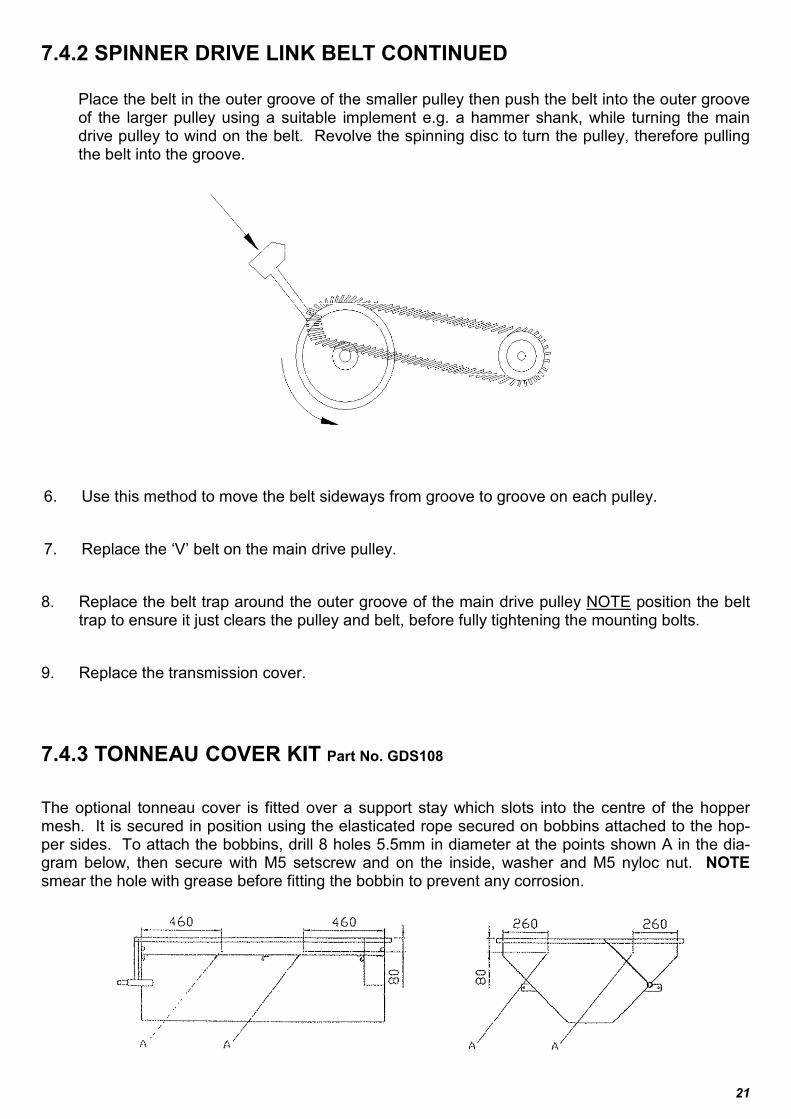
7.4.2 SPINNER DRIVE LINK BELT CONTINUED
Place the belt in the outer groove of the smaller pulley then push the belt into the outer groove of the larger pulley using a suitable implement e.g. a hammer shank, while turning the main drive pulley to wind on the belt. Revolve the spinning disc to turn the pulley, therefore pulling the belt into the groove.
6. Use this method to move the belt sideways from groove to groove on each pulley.
7. Replace the ‘V’ belt on the main drive pulley.
8. Replace the belt trap around the outer groove of the main drive pulley NOTE position the belt trap to ensure it just clears the pulley and belt, before fully tightening the mounting bolts.
9. Replace the transmission cover.
7.4.3 TONNEAU COVER KIT Part No. GDS108
The optional tonneau cover is fitted over a support stay which slots into the centre of the hopper mesh. It is secured in position using the elasticated rope secured on bobbins attached to the hop-per sides. To attach the bobbins, drill 8 holes 5.5mm in diameter at the points shown A in the dia-gram below, then secure with M5 setscrew and on the inside, washer and M5 nyloc nut. NOTE smear the hole with grease before fitting the bobbin to prevent any corrosion.

22
8 SPECIFICATIONS
Road Specification Off-Road Specification
Hopper Capacity 465 litres 465 litres
Carrying Capacity Approx 500kg dry salt Approx 500kg dry salt
Wheel Size 195/60 R14 27 x 7-14 Lug Tread
Offset Spreading Yes - Left and Right Yes - Left and Right
Hopper Metal Thickness 2mm 2mm
Drive Engagement Hand Lever Hand Lever
Towing Hitch 50mm Swivel Coupling 50mm Swivel Coupling
Mudguards Standard N/A
Lights Standard N/A
Unladen Weight (Stainless) 298kg 279kg
Unladen Weight(Painted) 306kg 287kg
OPTIONS
Standard Gearbox 1.5 - 10m Spread width Based on dry rock salt
High Speed Gearbox 3 - 14m Spread width Based on dry rock salt
GDS106 Flashing Beacon
GDS108 Tonneau Cover c/w Support
WT811 25 x 10-12 Flotation Wheels
Towing Clevis/ Jaw 45mm Clevis to take a 16mm pin
Towing Ring 30, 40, 50mm ID Rings avialable

23
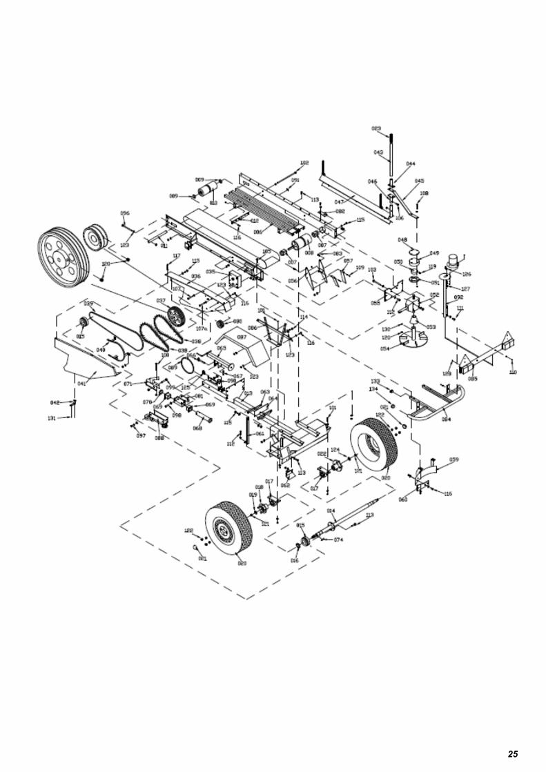
9 PARTS DIAGRAM AND PARTS LIST

24
Item Part Number Description
001 GDS200-001A Hopper
001 GDS250-001A Hopper Stainless Steel
002 GDS200-179 Hopper Deflector strip
003 GDS200-118 Hopper Front Deflector Strip
004 GDS200-007LA Conveyor Nearside Panel
005 GDS200-007RA Conveyor Offside panel
006 GDS200-017A Conveyor Bed
007 GDS200-109 Drive Roller Bearing
008 GDS200-108 Drive Roller
009 GDS200-126 Idle Pulley Seal
010 GDS200-110 Conveyor Belt Idle Roller
011 GDS200-049 Idle Roller Shaft
012 GDS200-119 Conveyor Belt Cleaner
013 GDS200-008A Chassis
014 GDS200-163A Axle
015 GDS200-105 Axle Drive Pulley
016 GDS200-125 Axle Pulley seal
017 GDS200-127 Bearing Pillow Block
018 GDS200-164 Wheel Drive-Hub
019 GDS200-038 Wheel Hub Washer
020 WT950 L/R / WT750 Wheel & Tyre Off Road/On Road
021 SA200-1010 End Cap 52 mm
022 SA900H Hub Heavy Duty
023 S201-30 Handle Grip
025 GDS200-032A Drive Engagement Handle
026 GDS200-030A Handle Centre Link
027 GDS200-053 Handle Link Pivot Pin
028 FCG04074SS Clip R 4 x 74
029 GDS200-114 Handle Linkage Spring
030 GDS200-046A Handle Bottom Link
030 GDS250-046A Handle Bottom Link Stainless Steel
031 GDS200-016A Drive Engagement Lever
032 GDS200-115 Engagement Lever Return Spring
033 GDS200-099A Idle Pulley Bush
034 GDS200-098 Idle Pulley
035 GDS200-103 Spur Reduction Gearbox
036 GDS200-009A Transmission Guard
036 GDS250-009A Transmission Guard Stainless Steel
037 GDS200-106 Spur Gearbox Pulley
038 GDS200-113 Rear Drive Belt
039 GDS200-112 Main Drive Belt
25

26
Item Part Number Description
040 GDS200-101A Belt Trap
041 GDS200-235A Transmission Guard Cover (Bolt on )
041 GDS250-235A Transmission Guard Cover (Bolt on ) Stainless Steel
042 GDS200-147 Transmission Guard Latch
043 GDS200-156 Agitator Handle
044 GDS200-070A Agitator Handle Assembly
044 GDS250-070A Agitator Handle Assembly Stainless Steel
045 GDS200-050 Agitator-Connecting Spring
046 GDS200-166A Spring Top Mounting
046 GDS250-166A Spring Top Mounting Stainless Steel
047 GDS200-021A Agitator
048 GDS200-012 Cam Housing Top Clamp Plate
048 GDS250-012 Cam Housing Top Clamp Plate Stainless Steel
049 GDS200-096 Cam Housing
050 GDS200-034/GDS200-234 Agitator Cam Std / High Speed
051 GDS200-097 Cam Housing Bottom Clamp Plate
052 GDS200-104/GDS200-204 Disc Gearbox Std/High Speed
053 GDS200-131 Spreader Disc Cone
054 GDS200-182SS Spreader Disc Assembly (Stainless steel)
055 GDS200-090 Rear Gearbox Mounting Profile
055 GDS250-090 Rear Gearbox Mounting Profile Stainless Steel
056 GDS200-132A Drop Chute
056 GDS250-132A Drop Chute Stainless Steel
057 GDS200-134A Drop Chute Side Deflector
057 GDS250-134A Drop Chute Side Deflector Stainless Steel
059 GDS200-044A Disc Deflector
059 GDS250-044A Disc Deflector Stainless Steel
060 GDS200-144 Disc Deflector Strip
061 GDS200-159SS Chassis – Hopper Brace
062 GDS200-062A Deflector Bracket
063 GDS200-085 Pressure Strip Clamp Plate
064 GDS200-120 Belt Cleaner Pressure Strip
065 GDS200-172A Jack
066 SLB600-07 Jack Pin
066 SLB600-07SS Jack Pin Stainless Steel
067 FCG03054SS Clip R 3 x 54
068 CM100-04 Draw Tube
069 CM100-03A Bush Nyloc
070 CM100-01A Thrust Washer
071 C900 Coupling
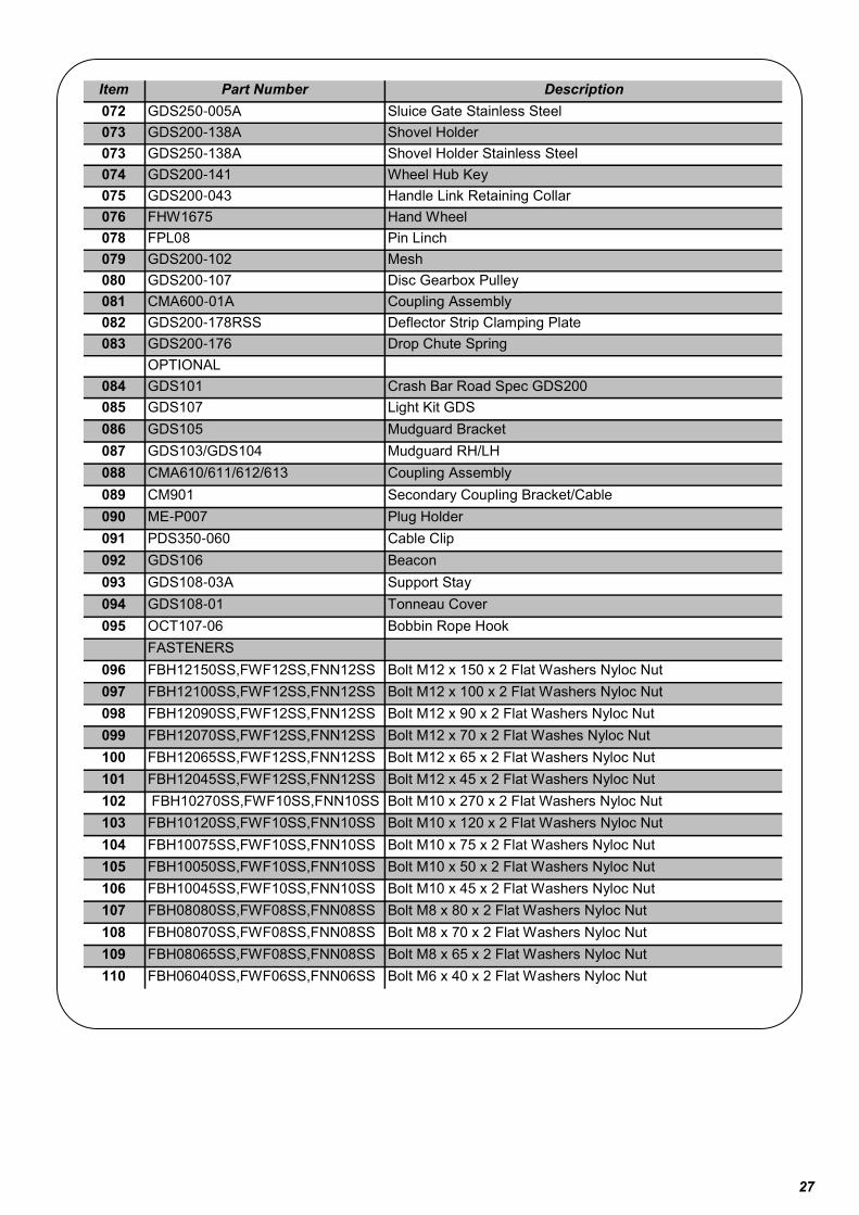
072 GDS200-005A Sluice Gate
27
Item Part Number Description
072 GDS250-005A Sluice Gate Stainless Steel
073 GDS200-138A Shovel Holder
073 GDS250-138A Shovel Holder Stainless Steel
074 GDS200-141 Wheel Hub Key
075 GDS200-043 Handle Link Retaining Collar
076 FHW1675 Hand Wheel
078 FPL08 Pin Linch
079 GDS200-102 Mesh
080 GDS200-107 Disc Gearbox Pulley
081 CMA600-01A Coupling Assembly
082 GDS200-178RSS Deflector Strip Clamping Plate
083 GDS200-176 Drop Chute Spring
OPTIONAL
084 GDS101 Crash Bar Road Spec GDS200
085 GDS107 Light Kit GDS
086 GDS105 Mudguard Bracket
087 GDS103/GDS104 Mudguard RH/LH
088 CMA610/611/612/613 Coupling Assembly
089 CM901 Secondary Coupling Bracket/Cable
090 ME-P007 Plug Holder
091 PDS350-060 Cable Clip
092 GDS106 Beacon
093 GDS108-03A Support Stay
094 GDS108-01 Tonneau Cover
095 OCT107-06 Bobbin Rope Hook
FASTENERS
096 FBH12150SS,FWF12SS,FNN12SS Bolt M12 x 150 x 2 Flat Washers Nyloc Nut
097 FBH12100SS,FWF12SS,FNN12SS Bolt M12 x 100 x 2 Flat Washers Nyloc Nut
098 FBH12090SS,FWF12SS,FNN12SS Bolt M12 x 90 x 2 Flat Washers Nyloc Nut
099 FBH12070SS,FWF12SS,FNN12SS Bolt M12 x 70 x 2 Flat Washes Nyloc Nut
100 FBH12065SS,FWF12SS,FNN12SS Bolt M12 x 65 x 2 Flat Washers Nyloc Nut
101 FBH12045SS,FWF12SS,FNN12SS Bolt M12 x 45 x 2 Flat Washers Nyloc Nut
102 FBH10270SS,FWF10SS,FNN10SS Bolt M10 x 270 x 2 Flat Washers Nyloc Nut
103 FBH10120SS,FWF10SS,FNN10SS Bolt M10 x 120 x 2 Flat Washers Nyloc Nut
104 FBH10075SS,FWF10SS,FNN10SS Bolt M10 x 75 x 2 Flat Washers Nyloc Nut
105 FBH10050SS,FWF10SS,FNN10SS Bolt M10 x 50 x 2 Flat Washers Nyloc Nut
106 FBH10045SS,FWF10SS,FNN10SS Bolt M10 x 45 x 2 Flat Washers Nyloc Nut
107 FBH08080SS,FWF08SS,FNN08SS Bolt M8 x 80 x 2 Flat Washers Nyloc Nut
108 FBH08070SS,FWF08SS,FNN08SS Bolt M8 x 70 x 2 Flat Washers Nyloc Nut
109 FBH08065SS,FWF08SS,FNN08SS Bolt M8 x 65 x 2 Flat Washers Nyloc Nut
110 FBH06040SS,FWF06SS,FNN06SS Bolt M6 x 40 x 2 Flat Washers Nyloc Nut

28
Item Part Number Description
111 FSH10035SS,FWF10SS,FNN10SS S/Screw M10 x 35 x 2 Flat washers Nyloc Nut
112 FSH10030SS,FWF10SS,FNN10SS S/Screw M10 x 30 x 2 Flat Washers Nyloc Nut
113 FSH10025SS,FWF10SS,FNN10SS S/Screw M10 x 25 x 2 Flat Washers Nyloc Nut
114 FSH08030SS,FWF08SS,FNN08SS S/Screw M8 x 30 x 2 Flat Washers Nyloc Nut
115 FSH08025SS,FWF08SS,FNN08SS S/Screw M8 x 25 x 2 Flat Washers Nyloc Nut
116 FSH08020SS,FWF08SS,FNN08SS S/Screw M8 x 20 x 2 Flat Washers Nyloc Nut
117 FSH08016SS,FWF08SS,FNN08SS S/Screw M8 x 16 x 2 Flat Washers Nyloc Nut
118 FSH05016SS,FWF05SS,FNN05SS S/Screw M5 x 16 x 2 Flat Washers Nyloc Nut
119 FSG10020SS G/Screw M10 x 20
120 FSG08008SS G/Screw M8 x 8
121 FNN16150 Nyloc Nut M16 x 1.5MM Pitch
122 SA200-1006 Wheel Nut M12
123 FWR08025SS Repair Washer M8 x 25
124 FWF16SS Flat Washer M16
125 FXS06 Shackle Galv 6 MM
126 S216-044 On/Off Toggle Switch
127 S216-045 On/Off Switch Boot
128 FSS06012 Screw S/Tap Pan/H
129 FPL06 Pin Linch 06 MM
130 FSG08010SS G/Screw M8 x10
131 FRP05010SS P/Rivet 4.8 x 10
132 TA102-03 Grease Nipple
133 FSH06016SS S/Screw Hex Head M6 x 16 SSA2
134 FIP025025 Insert Plastic 25 X 25 X 2-32 MM
135 FIP042026 Insert Plastic 42.4 OD X 2.6/4
136 MSU-C032 Clip Spring
137 FSD05016SS,FWF05SS,FNN05SS S/Screw M5 x 16 x 2 Flat Washers, Nyloc Nut
138 GDS200-239A Agitator Parking Mount
139 FSH08025SS,FWF08SS,FNN08SS S/Screw M8 x 25 x 2 Flat Washers Nyloc Nut

29
10 LOGIC MANUFACTURING PRODUCTS OWNER
This Logic Manufacturing product is guaranteed against faulty workmanship and materials for a period of 6 months from the date of purchase.
On Engine-Powered equipment, the engine manufactures guarantee will apply, any claims being subject to their terms and conditions.
All claims must be made in writing within 28 days of the alleged failure.
All claims must be made through the dealer who originally supplied the machine.
Any defective parts must be kept for inspection and if requested, sent to the factory or dealer.
The customer must bring equipment for repair to the dealer.
This guarantee becomes void if unauthorised modifications have been made, or if parts not manufactured, supplied or approved by Logic Manufacturing have been fitted to the machine.
We accept no liability for normal wear and tear, misuse or abuse, or where recommended maintenance has not been carried out.
All guarantee work must be authorised by Logic manufacturing prior to any work being done. Work carried out without our consent may not be reimbursed.

30
DECLARATION OF CONFORMITY
93 / 44 EEC
LOGIC MANUFACTURING LTD
Foundry Industrial Estate
Bridge End
HEXHAM
Northumberland
Product Type: GDS200/250—GROUND DRIVE SPREADER RANGE
Covered By Technical File Number: CE – GDS200
Serial Number:
Standards and Regulations Used:
The Supply of Machinery (Safety) Regulations 1992
HSE Guide Lines on ATV Equipment (Agric Sheet No. 33)
Place of Issue: United Kingdom
Name of Authorised Representative: S A WEIR
Position of Authorised Representative: PRODUCT DEVELOPMENT MANAGER
Declaration,
I declare that as the authorised representative, the above information in relation to the supply / manufacture of this product, is in conformity with the stated standards and other related documents following the provisions of 93/68EEC directives
Signature of Authorised Representative
Date: 05/07/2010
Top Related