


Languages
Pages
Legal

Product Bulletin FX10 "Standard" Issue Date 05 2004
© 2002 Johnson Controls, Inc. 1 Order Nr. DS 24.430 E, Rev. B www.johnsoncontrols.com
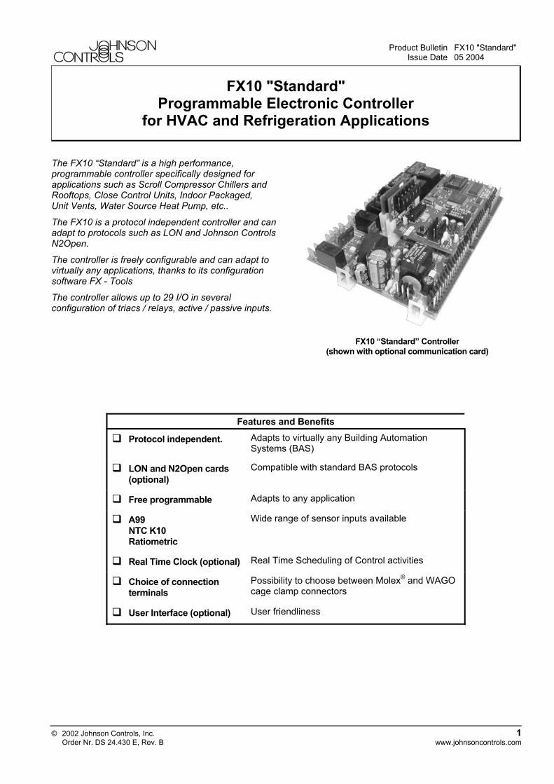
FX10 "Standard" Programmable Electronic Controller
for HVAC and Refrigeration Applications
The FX10 “Standard” is a high performance, programmable controller specifically designed for applications such as Scroll Compressor Chillers and Rooftops, Close Control Units, Indoor Packaged, Unit Vents, Water Source Heat Pump, etc..
The FX10 is a protocol independent controller and can adapt to protocols such as LON and Johnson Controls N2Open.
The controller is freely configurable and can adapt to virtually any applications, thanks to its configuration software FX - Tools
The controller allows up to 29 I/O in several configuration of triacs / relays, active / passive inputs.
FX10 “Standard” Controller
(shown with optional communication card)
Features and Benefits
Protocol independent. Adapts to virtually any Building Automation Systems (BAS)
LON and N2Open cards (optional)
Compatible with standard BAS protocols
Free programmable Adapts to any application
A99 NTC K10 Ratiometric
Wide range of sensor inputs available
Real Time Clock (optional) Real Time Scheduling of Control activities
Choice of connection terminals
Possibility to choose between Molex® and WAGO cage clamp connectors
User Interface (optional) User friendliness
2 FX10 "Standard"
Controller Overview
Input / Output • 6 analog inputs (AI) • 12 digital inputs (DI) • Up to 9 relays (DO) or 7 relays and 2 triacs • 2 Pulse Width Modulation Outputs (PWM)
User Interface (optional) A user interface can be associated to the FX10 for display and keyboard operations. A display link interface is necessary for the connection, see "Accessories" codes on page 8.
Communication Interface (optional) The FX10 can be integrated in supervisory systems thanks to plug-in communication cards. Several cards are available depending on the supported protocol: LON, N2Open.
Real Time Clock (optional) This Plug-in card allows the introduction of functions based on a weekly time schedule.
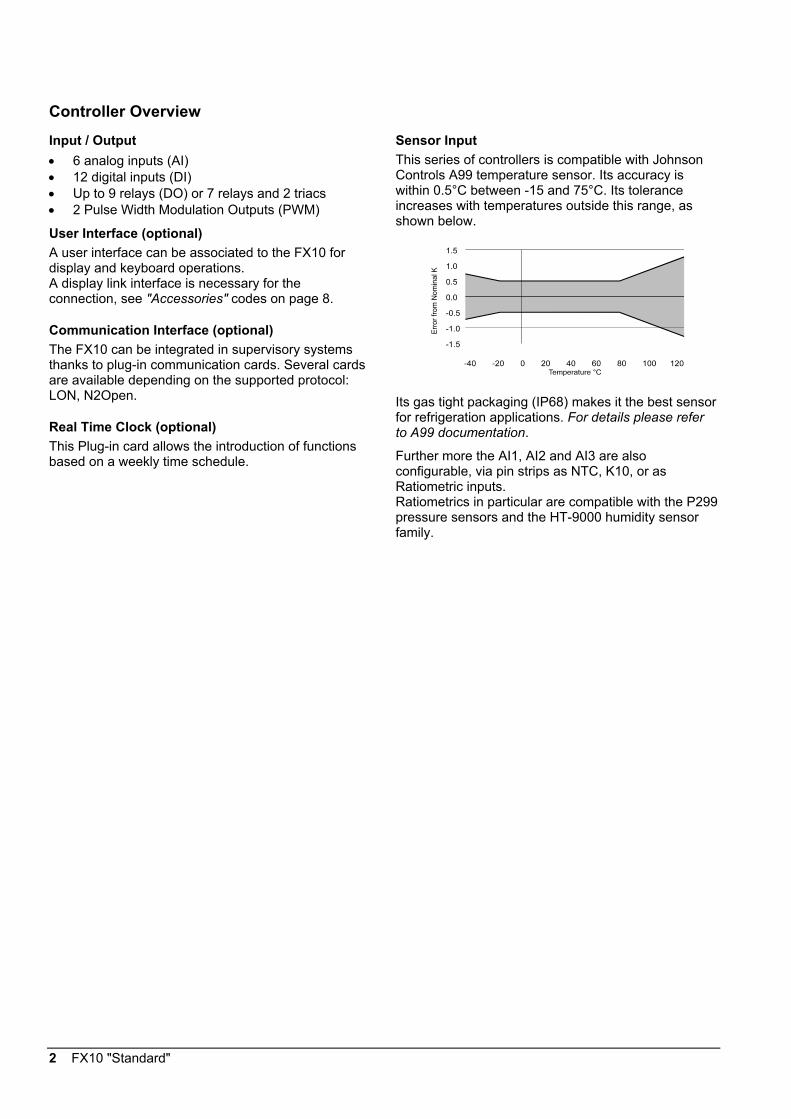
Sensor Input This series of controllers is compatible with Johnson Controls A99 temperature sensor. Its accuracy is within 0.5°C between -15 and 75°C. Its tolerance increases with temperatures outside this range, as shown below.
Its gas tight packaging (IP68) makes it the best sensor for refrigeration applications. For details please refer to A99 documentation.
Further more the AI1, AI2 and AI3 are also configurable, via pin strips as NTC, K10, or as Ratiometric inputs. Ratiometrics in particular are compatible with the P299 pressure sensors and the HT-9000 humidity sensor family.
FX10 "Standard" 3
Software and configuration The FX10 “Standard” is fully programmable with the Johnson Controls FX-Tools configuration software. The configuration is object oriented and free from any programming language. Several object libraries are available to quickly develop and/or customise an application. The software will be available under a license fee and will allow the full configuration of the control strategy and display application.
The applications available with the FX-TOOLS are:
FX-AppMaker: to develop and customise the control application and the network profile.
FX-UIMaker: to decide how to display data with one of the FX displays. Preview features included.
FX-Simulator: to test and debug the application on a PC before proceeding with the real hardware.
FX-Loader: to download to the target controller the developed control application and display configuration at the click of a button. N2Open, LON, BACnet MSTP protocol supported.
FX-CommPro: for the complete control of the network profile of the connected unit. Parameter configuration, machine tuning, default parameters saving for successive configurations are things all possible with the CommPro with the 3 protocol supported: N2Open, LON, BACnet MSTP
The software package can also be tested and evaluated in demo version. This version allows the complete use and testing of the software package but it will allow to download the developed strategy only to a demo case or to a demo controller.
4 FX10 "Standard"
Security The FX-TOOLS and the FX controllers comes with an embedded security features based on the use of two IDs: the family ID and the customer ID.
Family ID: permits to discriminate among an FX05, FX10 or FX15. The first thing that an FX designer does when he starts developing an application is to choose the target device (target controller). An application developed for an FX15 will not be downloadable to an FX05, the family ID of the controller and the one of the application do not match. Of course, in order to be able to reuse the work done with one controller with another controller of the family, the AppMaker allows to re-edit the application so to make it compatible with a different FX controller from the original one.
Customer ID: the licensed tools will come with 2 customer IDs, a public one and a private one. The application saved with the public ID will be downloadable to all standard FX controllers (provided the family ID matches). These public applications will also be readable and editable by whoever has the FX-TOOLs and access to these source application files (note that it is not possible to upload the application file from the controller).
The application saved with the private customer ID will also be downloadable to all FX standard controllers but, from that moment on, the controller is automatically baptised with the specific private ID. From that moment on that controller will only be downloadable with applications that has a matching private ID. Moreover the application source files saved with the private ID can only be read and edited by FX designers that have installed in their PC the very same private ID.
The DEMO ID is a particular private ID that is only compatible with the demo controllers or the demo cases (see "Ordering Codes" on page 23).
WARNING
Shock Hazard
When servicing make sure that:
• The electrical supply to the controller is switched off to avoid possible damage to the equipment, personal injury or shock.
• You do not touch or attempt to connect or disconnect wires.

FX10 "Standard" 5
I/O Details Type Remark/Application Analog Input (AI) AI1, AI2, AI3
A99 Range: -40 to 100°C Accuracy: ± 0.5°C @ 20°C ambient (sensor not included) NTC (K10) Range: 0 ÷ 100°C Accuracy: ±0.5°C @ 20°C ambient (sensor not included) Ratiometric Range: 0.5 to 4.5 V Resolution: 10 mV
Software configurable and jumper selectable. See "Jumper Configuration" on page 7. Application: temperature, humidity or pressure
AI4, AI5, AI6 A99 Range: -40 to 100°C Accuracy: ± 0.5°C @ 20°C ambient (sensor error not included)
Application: temperature, humidity pressure (through input converter)
Digital Input (DI) DI1, DI2 Voltage free contacts with safety control feature Disconnect respectively DO1 and DO2
relay outputs. Function selectable through jumpers. See "Note" on the next page. Application: high temperature/pressure cut out
DI3, DI4, DI5, DI6 Voltage free contacts DI7, DI8, DI9, DI10, DI11, DI12
24 VAC externally powered contacts See "Mandatory wiring" on the next page
Digital Output (DO) DO1, DO2 SPST 8(3)A, 250 VAC relays (low power relay version)
or SPST 25A, 250 VAC relays (high power relay version)
DO3, DO4, DO5, DO7, DO8, DO9
SPST 5(2)A, 250 VAC relays or 0,5A / 24 VAC triacs
DO6 SPDT 5(2)A, 250 VAC relays Or 0,5A / 24 VAC triacs
Outputs DO3 ÷ DO9 can be freely specified either as relay or as triac. The specific hardware code will be created upon minimum order. Other Outputs PWM 9 V (supplied by FX10), 50 mA max, 100 Hz LED Signal to LED of a JC room command module 10 mA at 2V
6 FX10 "Standard"
123
123
W1 W2
WARNING
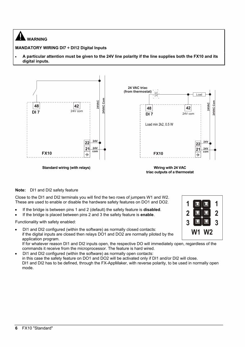
MANDATORY WIRING DI7 ÷ DI12 Digital Inputs
• A particular attention must be given to the 24V line polarity if the line supplies both the FX10 and its digital inputs.
24VA
C C
om
24VA
C
DI 748 42
24V
24Vcom
2221
FX10
24V com
24VA
C C
om
24VA
C
DI 748 42
24V
24Vcom
2221
Load
FX10
24 VAC triac(from thermostat)
24V com
Standard wiring (with relays) Wiring with 24 VAC triac outputs of a thermostat
Note: DI1 and DI2 safety feature
Close to the DI1 and DI2 terminals you will find the two rows of jumpers W1 and W2. These are used to enable or disable the hardware safety features on DO1 and DO2.
• If the bridge is between pins 1 and 2 (default) the safety feature is disabled. • If the bridge is placed between pins 2 and 3 the safety feature is enable.
Functionality with safety enabled:
• DI1 and DI2 configured (within the software) as normally closed contacts: if the digital inputs are closed then relays DO1 and DO2 are normally piloted by the application program. If for whatever reason DI1 and DI2 inputs open, the respective DO will immediately open, regardless of the commands it receive from the microprocessor. The feature is hard wired.
• DI1 and DI2 configured (within the software) as normally open contacts: in this case the safety feature on DO1 and DO2 will be activated only if DI1 and/or DI2 will close. DI1 and DI2 has to be defined, through the FX-AppMaker, with reverse polarity, to be used in normally open mode.
Load min 2k2, 0.5 W
FX10 "Standard" 7
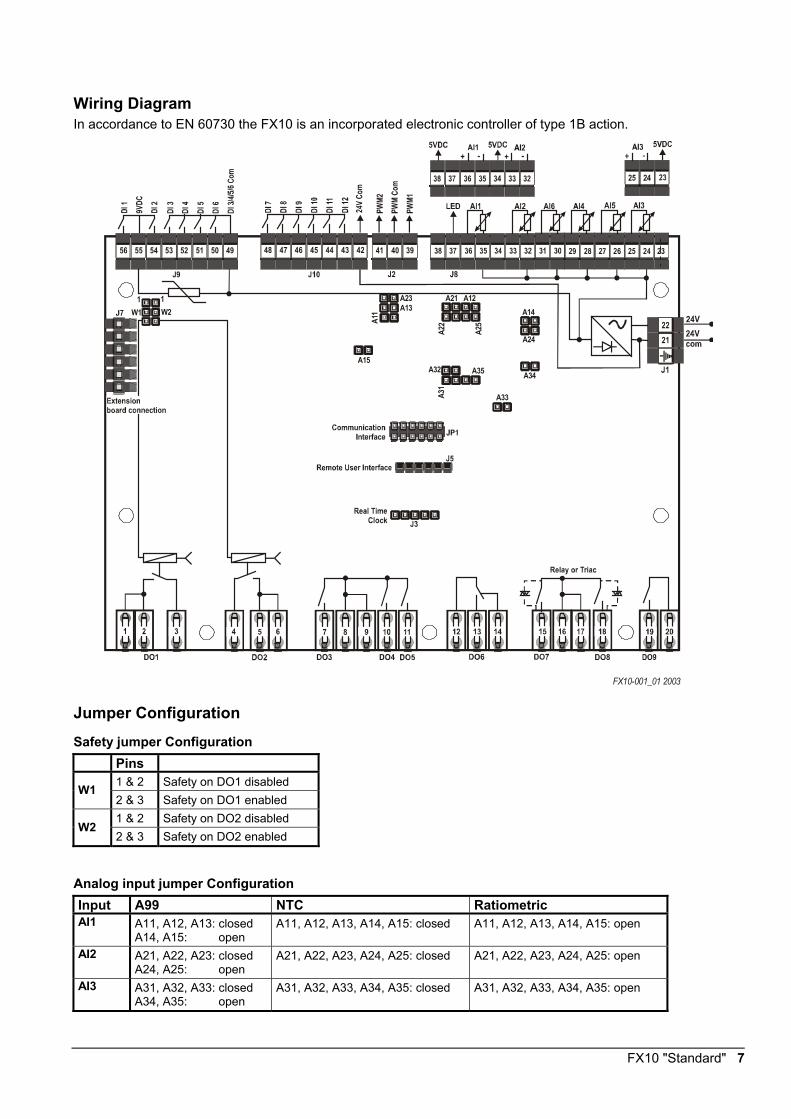
Wiring Diagram In accordance to EN 60730 the FX10 is an incorporated electronic controller of type 1B action.
2221
55 54 53 52 51 50 49 48 47 46 45 44 43 42 41 40 39
A14A21A23
A13
A32 A35
A33
A12
A24
A34
A22
A25
A31
A11
A15
56
1W1 W2
1
FX10-001_01 2003
Jumper Configuration
Safety jumper Configuration Pins
1 & 2 Safety on DO1 disabled W1 2 & 3 Safety on DO1 enabled 1 & 2 Safety on DO2 disabled
W2 2 & 3 Safety on DO2 enabled
Analog input jumper Configuration Input A99 NTC Ratiometric AI1 A11, A12, A13: closed
A14, A15: open A11, A12, A13, A14, A15: closed A11, A12, A13, A14, A15: open
AI2 A21, A22, A23: closed A24, A25: open
A21, A22, A23, A24, A25: closed A21, A22, A23, A24, A25: open
AI3 A31, A32, A33: closed A34, A35: open
A31, A32, A33, A34, A35: closed A31, A32, A33, A34, A35: open
8 FX10 "Standard"
Accessories
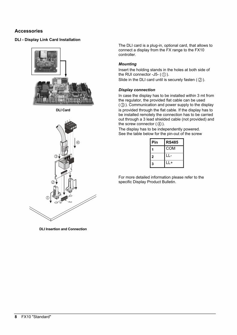
DLI - Display Link Card Installation
DLI Card
RUI
123
DLI Insertion and Connection
The DLI card is a plug-in, optional card, that allows to connect a display from the FX range to the FX10 controller.
Mounting Insert the holding stands in the holes at both side of the RUI connector -J5- ( ). Slide in the DLI card until is securely fasten ( ).
Display connection In case the display has to be installed within 3 mt from the regulator, the provided flat cable can be used ( ). Communication and power supply to the display is provided through the flat cable. If the display has to be installed remotely the connection has to be carried out through a 3 lead shielded cable (not provided) and the screw connector ( ). The display has to be independently powered. See the table below for the pin-out of the screw
Pin RS485 1 COM
2 LL-
3 LL+
For more detailed information please refer to the specific Display Product Bulletin.
FX10 "Standard" 9
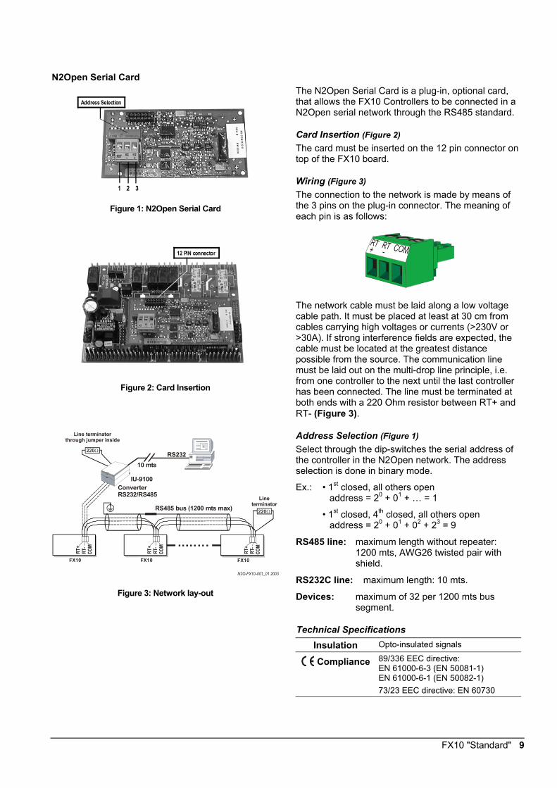
N2Open Serial Card
Address Selection
1 2 3 Figure 1: N2Open Serial Card
12 PIN connector
Figure 2: Card Insertion
RT+
RT-
COM
FX10
RT+
RT-
COM
FX10
RT+
RT-
COM
FX10
220ΩRS485 bus (1200 mts max)
220ΩRS232
ConverterRS232/RS485
IU-9100
Line terminator
Line terminatorthrough jumper inside
10 mts
N2O-FX10-001_01 2003 Figure 3: Network lay-out
The N2Open Serial Card is a plug-in, optional card, that allows the FX10 Controllers to be connected in a N2Open serial network through the RS485 standard.
Card Insertion (Figure 2)
The card must be inserted on the 12 pin connector on top of the FX10 board.
Wiring (Figure 3) The connection to the network is made by means of the 3 pins on the plug-in connector. The meaning of each pin is as follows:
The network cable must be laid along a low voltage cable path. It must be placed at least at 30 cm from cables carrying high voltages or currents (>230V or >30A). If strong interference fields are expected, the cable must be located at the greatest distance possible from the source. The communication line must be laid out on the multi-drop line principle, i.e. from one controller to the next until the last controller has been connected. The line must be terminated at both ends with a 220 Ohm resistor between RT+ and RT- (Figure 3).
Address Selection (Figure 1) Select through the dip-switches the serial address of the controller in the N2Open network. The address selection is done in binary mode.
Ex.: • 1st closed, all others open address = 20 + 01 + … = 1
• 1st closed, 4th closed, all others open address = 20 + 01 + 02 + 23 = 9
RS485 line: maximum length without repeater: 1200 mts, AWG26 twisted pair with shield.
RS232C line: maximum length: 10 mts.
Devices: maximum of 32 per 1200 mts bus segment.
Technical Specifications Insulation Opto-insulated signals Compliance 89/336 EEC directive:
EN 61000-6-3 (EN 50081-1) EN 61000-6-1 (EN 50082-1) 73/23 EEC directive: EN 60730
10 FX10 "Standard"
LON Serial Card
1 2 3
Service Spin
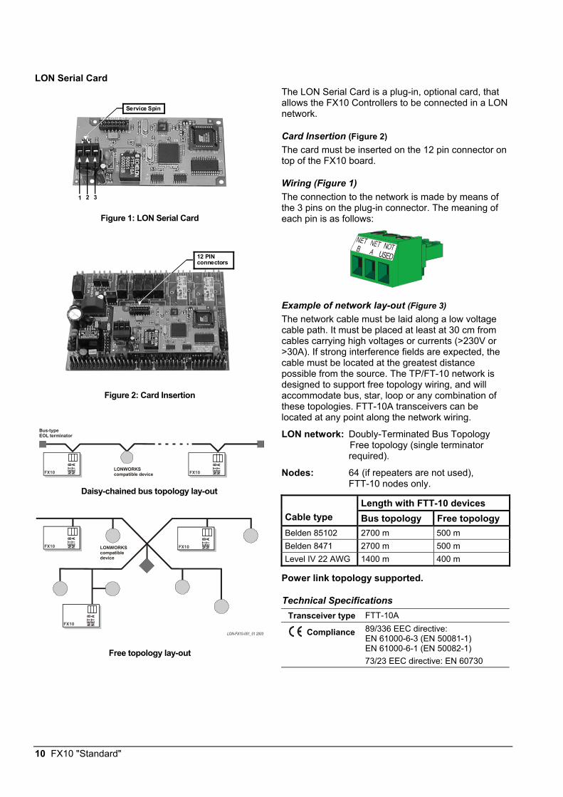
Figure 1: LON Serial Card
12 PIN connectors
Figure 2: Card Insertion
LONWORKScompatible device
LONWORKScompatible device
Bus-type EOL terminator
FX10 NET A
NET
B
FX10 NET A
NET
B
FX10 NET
ANE
T B
FX10 NET A
NET
B
FX10 NET A
NET
B
LON-FX10-001_01 2003 Free topology lay-out
The LON Serial Card is a plug-in, optional card, that allows the FX10 Controllers to be connected in a LON network.
Card Insertion (Figure 2) The card must be inserted on the 12 pin connector on top of the FX10 board.
Wiring (Figure 1) The connection to the network is made by means of the 3 pins on the plug-in connector. The meaning of each pin is as follows:
Example of network lay-out (Figure 3) The network cable must be laid along a low voltage cable path. It must be placed at least at 30 cm from cables carrying high voltages or currents (>230V or >30A). If strong interference fields are expected, the cable must be located at the greatest distance possible from the source. The TP/FT-10 network is designed to support free topology wiring, and will accommodate bus, star, loop or any combination of these topologies. FTT-10A transceivers can be located at any point along the network wiring.
LON network: Doubly-Terminated Bus Topology Free topology (single terminator required).
Nodes: 64 (if repeaters are not used), FTT-10 nodes only.
Length with FTT-10 devices Cable type Bus topology Free topology Belden 85102 2700 m 500 m Belden 8471 2700 m 500 m Level IV 22 AWG 1400 m 400 m
Power link topology supported.
Technical Specifications Transceiver type FTT-10A
Compliance 89/336 EEC directive: EN 61000-6-3 (EN 50081-1) EN 61000-6-1 (EN 50082-1) 73/23 EEC directive: EN 60730
Daisy-chained bus topology lay-out
FX10 "Standard" 11
Input Converter Module 4 - 20 mA to A99
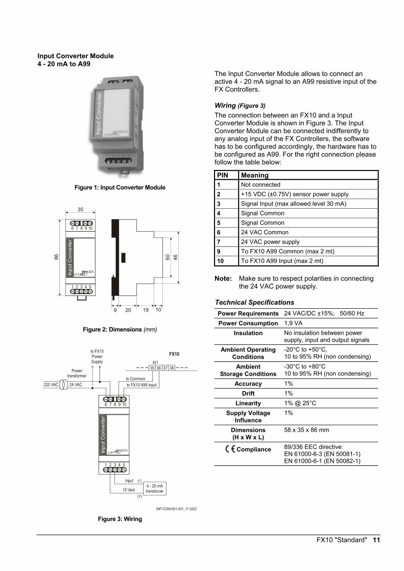
Figure 1: Input Converter Module
Inpu
t Con
verte
r
1
6
4
9
5
10
35
86 4660
9 20 19 10 Figure 2: Dimensions (mm)
Powertransformer
Inpu
t Con
verte
r
1
6
4
9
5
10
INP-CONV001-001_11 2002
4 - 20 mAtransducer
(-)
(+)
220 VAC 24 VAC
to FX10PowerSupply
to FX10 A99 Inputto Common
35 36 37 38AI1
FX10
Figure 3: Wiring
The Input Converter Module allows to connect an active 4 - 20 mA signal to an A99 resistive input of the FX Controllers.
Wiring (Figure 3) The connection between an FX10 and a Input Converter Module is shown in Figure 3. The Input Converter Module can be connected indifferently to any analog input of the FX Controllers, the software has to be configured accordingly, the hardware has to be configured as A99. For the right connection please follow the table below: PIN Meaning 1 Not connected 2 +15 VDC (±0.75V) sensor power supply 3 Signal Input (max allowed level 30 mA) 4 Signal Common 5 Signal Common 6 24 VAC Common 7 24 VAC power supply 9 To FX10 A99 Common (max 2 mt) 10 To FX10 A99 Input (max 2 mt)
Note: Make sure to respect polarities in connecting
the 24 VAC power supply.
Technical Specifications Power Requirements 24 VAC/DC ±15%; 50/60 Hz Power Consumption 1,9 VA
Insulation No insulation between power supply, input and output signals
Ambient Operating Conditions
-20°C to +50°C, 10 to 95% RH (non condensing)
Ambient Storage Conditions
-30°C to +80°C 10 to 95% RH (non condensing)
Accuracy 1% Drift 1%
Linearity 1% @ 25°C Supply Voltage
Influence 1%
Dimensions (H x W x L)
58 x 35 x 86 mm
Compliance 89/336 EEC directive: EN 61000-6-3 (EN 50081-1) EN 61000-6-1 (EN 50082-1)
12 FX10 "Standard"
Input Convert Module 0 - 10 V to A99
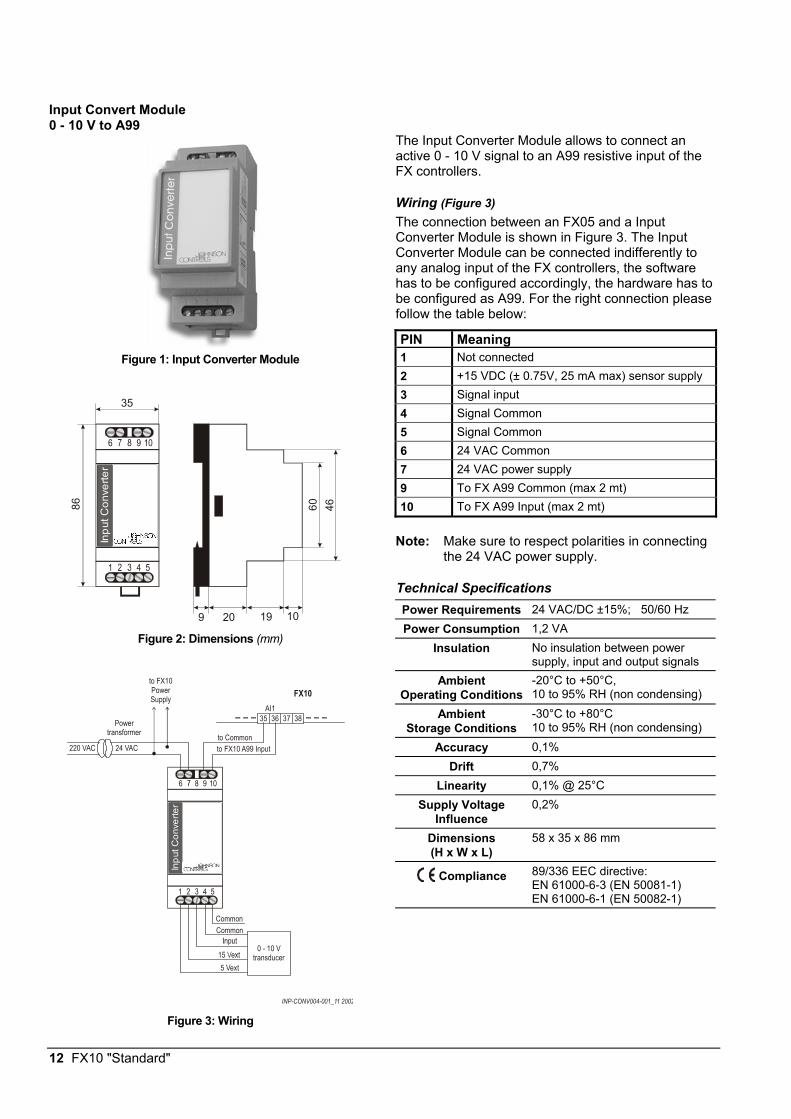
Figure 1: Input Converter Module
Inpu
t Con
verte
r
1
6
4
9
5
10
35
86 4660
9 20 19 10
Figure 2: Dimensions (mm)
Powertransformer
Inpu
t Con
verte
r
1
6
4
9
5
10
INP-CONV004-001_11 2002
0 - 10 Vtransducer
220 VAC 24 VAC
to FX10PowerSupply
to FX10 A99 Inputto Common
35 36 37 38AI1
FX10
5 Vext
CommonCommon
Figure 3: Wiring
The Input Converter Module allows to connect an active 0 - 10 V signal to an A99 resistive input of the FX controllers.
Wiring (Figure 3) The connection between an FX05 and a Input Converter Module is shown in Figure 3. The Input Converter Module can be connected indifferently to any analog input of the FX controllers, the software has to be configured accordingly, the hardware has to be configured as A99. For the right connection please follow the table below: PIN Meaning 1 Not connected 2 +15 VDC (± 0.75V, 25 mA max) sensor supply 3 Signal input 4 Signal Common 5 Signal Common 6 24 VAC Common 7 24 VAC power supply 9 To FX A99 Common (max 2 mt) 10 To FX A99 Input (max 2 mt)
Note: Make sure to respect polarities in connecting
the 24 VAC power supply.
Technical Specifications Power Requirements 24 VAC/DC ±15%; 50/60 Hz Power Consumption 1,2 VA
Insulation No insulation between power supply, input and output signals
Ambient Operating Conditions
-20°C to +50°C, 10 to 95% RH (non condensing)
Ambient Storage Conditions
-30°C to +80°C 10 to 95% RH (non condensing)
Accuracy 0,1% Drift 0,7%
Linearity 0,1% @ 25°C Supply Voltage
Influence 0,2%
Dimensions (H x W x L)
58 x 35 x 86 mm
Compliance 89/336 EEC directive: EN 61000-6-3 (EN 50081-1) EN 61000-6-1 (EN 50082-1)
FX10 "Standard" 13
Output Converter PWM to 0-10 V
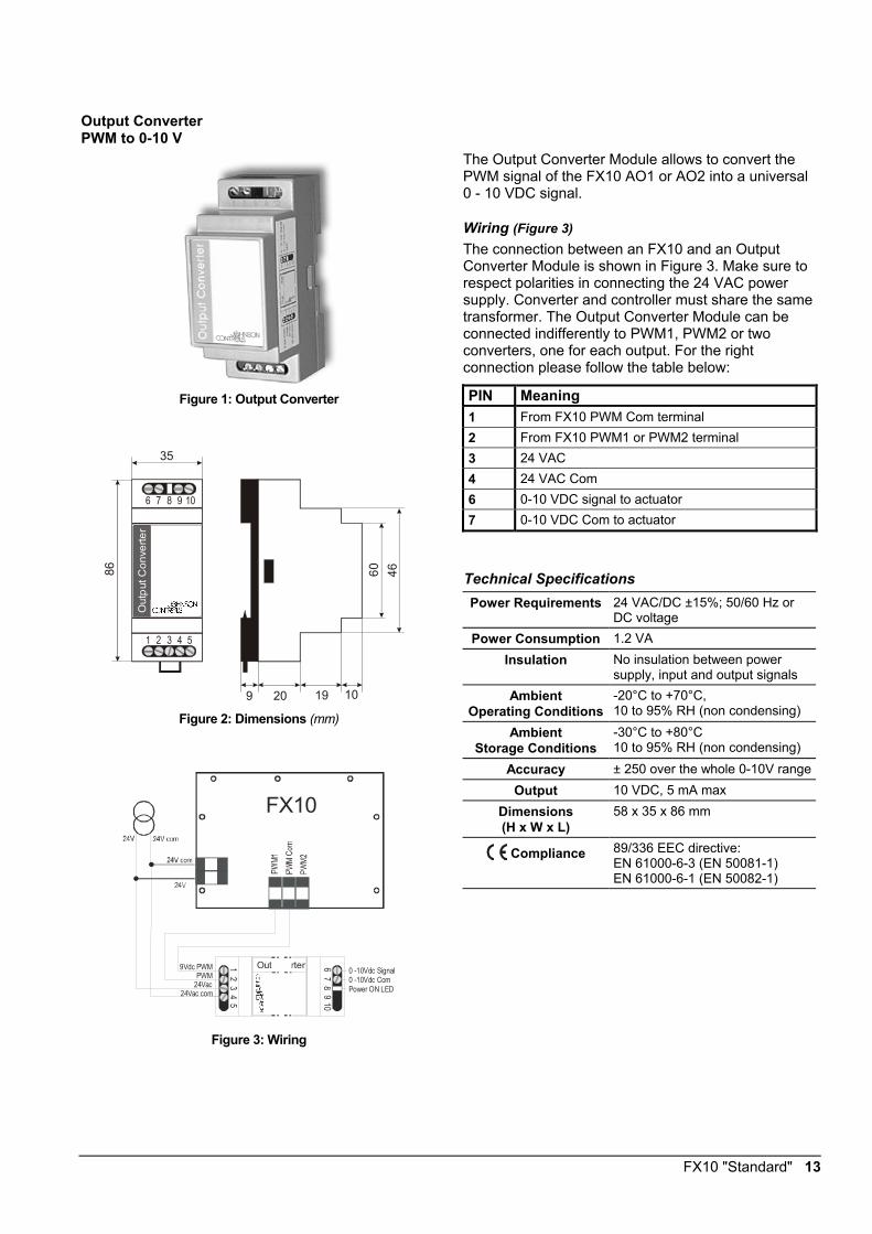
Figure 1: Output Converter
Out
put C
onve
rter
1
6
4
9
5
10
35
86 4660
9 20 19 10
Figure 2: Dimensions (mm)
rterOut1 6
4 9
5 10
0 -10Vdc Signal0 -10Vdc ComPower ON LED
PWM24Vac
24Vac com
9Vdc PWM
FX10
Figure 3: Wiring
The Output Converter Module allows to convert the PWM signal of the FX10 AO1 or AO2 into a universal 0 - 10 VDC signal.
Wiring (Figure 3) The connection between an FX10 and an Output Converter Module is shown in Figure 3. Make sure to respect polarities in connecting the 24 VAC power supply. Converter and controller must share the same transformer. The Output Converter Module can be connected indifferently to PWM1, PWM2 or two converters, one for each output. For the right connection please follow the table below:
PIN Meaning 1 From FX10 PWM Com terminal 2 From FX10 PWM1 or PWM2 terminal 3 24 VAC 4 24 VAC Com 6 0-10 VDC signal to actuator 7 0-10 VDC Com to actuator
Technical Specifications Power Requirements 24 VAC/DC ±15%; 50/60 Hz or
DC voltage Power Consumption 1.2 VA
Insulation No insulation between power supply, input and output signals
Ambient Operating Conditions
-20°C to +70°C, 10 to 95% RH (non condensing)
Ambient Storage Conditions
-30°C to +80°C 10 to 95% RH (non condensing)
Accuracy ± 250 over the whole 0-10V rangeOutput 10 VDC, 5 mA max
Dimensions (H x W x L)
58 x 35 x 86 mm
Compliance 89/336 EEC directive: EN 61000-6-3 (EN 50081-1) EN 61000-6-1 (EN 50082-1)
14 FX10 "Standard"
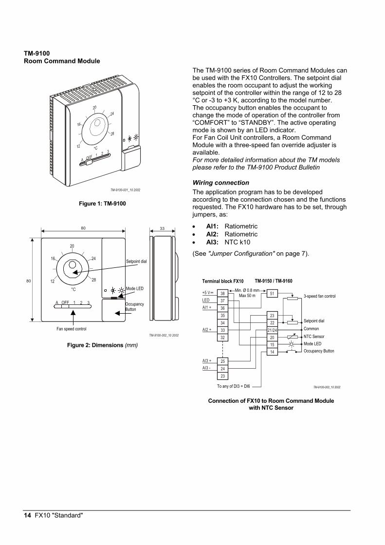
TM-9100 Room Command Module
TM-9100-001_10 2002
Figure 1: TM-9100
TM-9100-002_10 2002
A OFF 1 2 3
80
80
33
12
16
20
24
28
°C
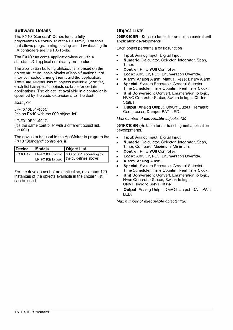
Figure 2: Dimensions (mm)
The TM-9100 series of Room Command Modules can be used with the FX10 Controllers. The setpoint dial enables the room occupant to adjust the working setpoint of the controller within the range of 12 to 28 °C or -3 to +3 K, according to the model number. The occupancy button enables the occupant to change the mode of operation of the controller from “COMFORT” to “STANDBY”. The active operating mode is shown by an LED indicator. For Fan Coil Unit controllers, a Room Command Module with a three-speed fan override adjuster is available. For more detailed information about the TM models please refer to the TM-9100 Product Bulletin
Wiring connection The application program has to be developed according to the connection chosen and the functions requested. The FX10 hardware has to be set, through jumpers, as:
• AI1: Ratiometric • AI2: Ratiometric • AI3: NTC k10
(See "Jumper Configuration" on page 7).
38 51373635 2334 22
25
33 21/24
24
32 201514
23
TM-9100-003_10 2002
+5 VLEDAI1 +
AI2 +
AI3 +AI3 -
Connection of FX10 to Room Command Module with NTC Sensor
Setpoint dial
Mode LED
Occupancy Button
Fan speed control
Terminal block FX10 TM-9150 / TM-9160 Min. Ø 0.8 mm
Max 50 m 3-speed fan control
Setpoint dial Common NTC Sensor Mode LED Occupancy Button
To any of DI3 ÷ DI6

FX10 "Standard" 15
DisplaysThe FX10 "Standard" can have one user interface, either local or remote. The display is optional, which means that the controller can work also without any display plugged-in.
• LOCAL: up to 3 mt from the controller, power supply and data communication via the flat telephone cable included in the DLI kit (LP-KIT000-000C).
• REMOTE: up to 300 mt from the controller. The display must be independently powered, the data communication is done via a 3 pole shielded cable (not provided) connected to the additional screw connector on the DLI kit.
For more details about the connection possibilities please refer to the specific display Product Bulletin.
The display models connectable to the FX10 "Standard" are:
• LP-DIS65P00-0C: Large User Interface, panel, flush mount or hand held, 4x20 backlit LCD, IP54, extended temperature range: -20° C to +50° C, standard JCI front-plate. The front-plate is fully customisable upon minimum order, see "LUI display" Product Bulletin for more information.
• LP-DIS60P00-0C / LP-DIS60P01-0C: Medium User Interface, 4x20 backlit LCD, IP54, extended temperature range: -20°C to +50°C. Panel mount, non-isolated version / wall mount isolated version.
• LP-DIS50P00-0C: Small User Interface,
panel mount, 3 LED digits. IP54. Temperature range: -20°C to +60°C.
16 FX10 "Standard"
Software Details The FX10 "Standard" Controller is a fully programmable controller of the FX family. The tools that allows programming, testing and downloading the FX controllers are the FX-Tools.
The FX10 can come application-less or with a standard JCI application already pre-loaded.
The application building philosophy is based on the object structure: basic blocks of basic functions that inter-connected among them build the application. There are several lists of objects available (2 so far), each list has specific objects suitable for certain applications. The object list available in a controller is specified by the code extension after the dash.
Example:
LP-FX10B01-000C (it’s an FX10 with the 000 object list)
LP-FX10B01-001C (it’s the same controller with a different object list, the 001)
The device to be used in the AppMaker to program the FX10 "Standard" controllers is:
Device Models Object List FX10B1x LP-FX10B0x-xxx
LP-FX10B1x-xxx 000 or 001 according to the guidelines above
For the development of an application, maximum 120 instances of the objects available in the chosen list, can be used.
Object Lists 000FX10BR - Suitable for chiller and close control unit application developments
Each object performs a basic function
• Input: Analog Input, Digital Input. • Numeric: Calculator, Selector, Integrator, Span,
Timer. • Control: PI, On/Off Controller. • Logic: And, Or, PLC, Enumeration Override. • Alarm: Analog Alarm, Manual Reset Binary Alarm. • Special: System Resource, General Setpoint,
Time Scheduler, Time Counter, Real Time Clock. • Unit Conversion: Convert, Enumeration to logic,
HVAC Generator Status, Switch to logic, Chiller Status.
• Output: Analog Output, On/Off Output, Hermetic Compressor, Damper PAT, LED.
Max number of executable objects: 120 001FX10BR (Suitable for air handling unit application developments)
• Input: Analog Input, Digital Input. • Numeric: Calculator, Selector, Integrator, Span,
Timer, Compare, Maximum, Minimum. • Control: PI, On/Off Controller. • Logic: And, Or, PLC, Enumeration Override. • Alarm: Analog Alarm. • Special: System Resource, General Setpoint,
Time Scheduler, Time Counter, Real Time Clock. • Unit Conversion: Convert, Enumeration to logic,
Hvac Generator Status, Switch to logic, UNVT_logic to SNVT_state.
• Output: Analog Output, On/Off Output, DAT, PAT, LED.
Max number of executable objects: 120
FX10 "Standard" 17
Metasys Integration The FX10 is fully programmable and customisable both in terms of control application and network profile. The network profile in particular, i.e. the list of variables and parameters available through the network, is not univocally determined but depends on the application loaded to the controller. For this reason the FX10, as well as all the other controllers of the FX family, are integrated to Metasys as VND - N2-Compatible Vendor Device.
The FX-Tools, that are used to develop the controller strategy, automatically print out a file (.PRN) that contains all the relevant information to integrate the controller load with a specific application to an N30 or NCM supervisory controller. The PRN file contains a column labelled Point Type and a column labelled Point Address. This information have to be used when specifying Network Point Type and Network Point Address in an N30 or NCM.
Note: When you name points in an N30 or NCM, you can use the names shown in the Long Name column (for example, Zone TEMP) for consistency, or you can create new names.
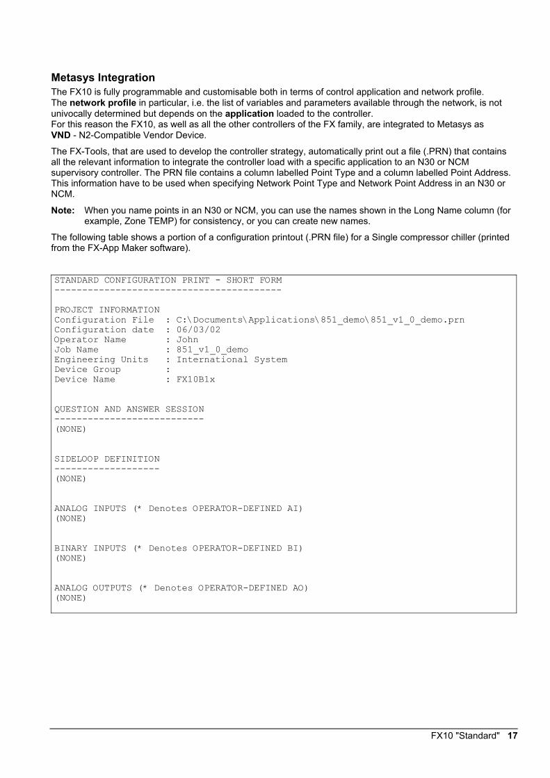
The following table shows a portion of a configuration printout (.PRN file) for a Single compressor chiller (printed from the FX-App Maker software).
STANDARD CONFIGURATION PRINT - SHORT FORM ----------------------------------------- PROJECT INFORMATION Configuration File : C:\Documents\Applications\851_demo\851_v1_0_demo.prn Configuration date : 06/03/02 Operator Name : John Job Name : 851_v1_0_demo Engineering Units : International System Device Group : Device Name : FX10B1x QUESTION AND ANSWER SESSION --------------------------- (NONE) SIDELOOP DEFINITION ------------------- (NONE) ANALOG INPUTS (* Denotes OPERATOR-DEFINED AI) (NONE) BINARY INPUTS (* Denotes OPERATOR-DEFINED BI) (NONE) ANALOG OUTPUTS (* Denotes OPERATOR-DEFINED AO) (NONE)
18 FX10 "Standard"
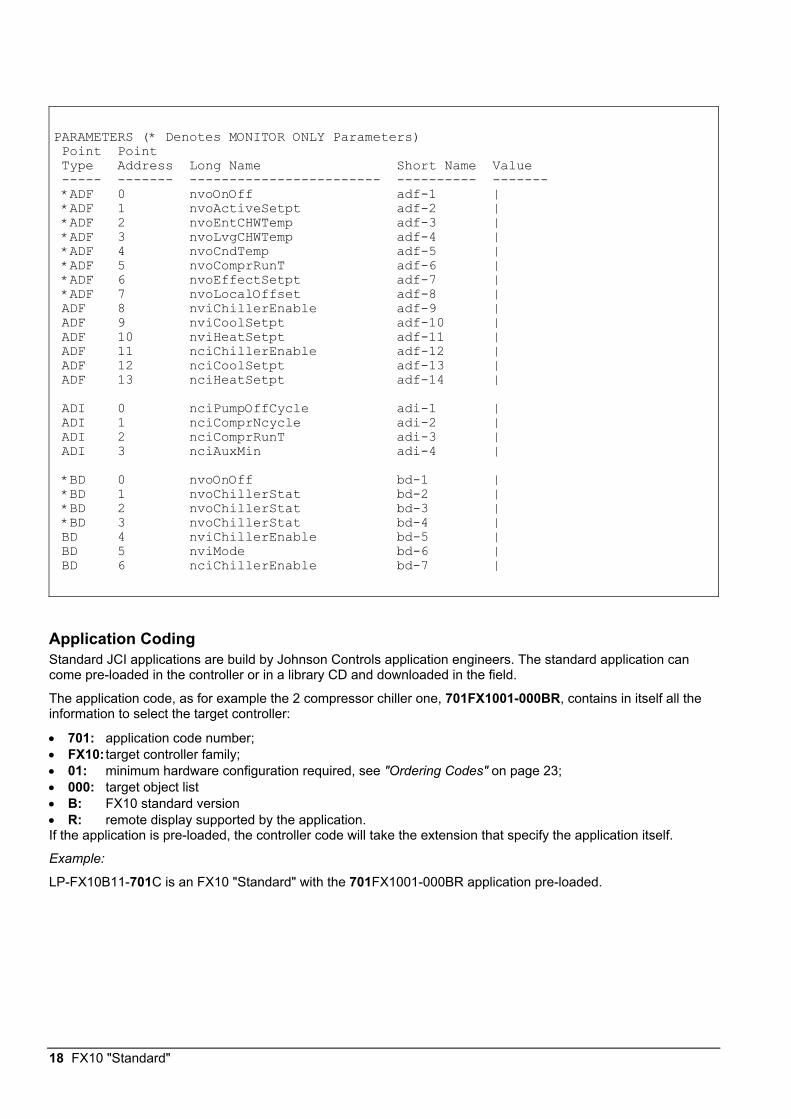
PARAMETERS (* Denotes MONITOR ONLY Parameters) Point Point Type Address Long Name Short Name Value ----- ------- ------------------------ ---------- ------- *ADF 0 nvoOnOff adf-1 | *ADF 1 nvoActiveSetpt adf-2 | *ADF 2 nvoEntCHWTemp adf-3 | *ADF 3 nvoLvgCHWTemp adf-4 | *ADF 4 nvoCndTemp adf-5 | *ADF 5 nvoComprRunT adf-6 | *ADF 6 nvoEffectSetpt adf-7 | *ADF 7 nvoLocalOffset adf-8 | ADF 8 nviChillerEnable adf-9 | ADF 9 nviCoolSetpt adf-10 | ADF 10 nviHeatSetpt adf-11 | ADF 11 nciChillerEnable adf-12 | ADF 12 nciCoolSetpt adf-13 | ADF 13 nciHeatSetpt adf-14 | ADI 0 nciPumpOffCycle adi-1 | ADI 1 nciComprNcycle adi-2 | ADI 2 nciComprRunT adi-3 | ADI 3 nciAuxMin adi-4 | *BD 0 nvoOnOff bd-1 | *BD 1 nvoChillerStat bd-2 | *BD 2 nvoChillerStat bd-3 | *BD 3 nvoChillerStat bd-4 | BD 4 nviChillerEnable bd-5 | BD 5 nviMode bd-6 | BD 6 nciChillerEnable bd-7 |
Application Coding Standard JCI applications are build by Johnson Controls application engineers. The standard application can come pre-loaded in the controller or in a library CD and downloaded in the field.
The application code, as for example the 2 compressor chiller one, 701FX1001-000BR, contains in itself all the information to select the target controller:
• 701: application code number; • FX10: target controller family; • 01: minimum hardware configuration required, see "Ordering Codes" on page 23; • 000: target object list • B: FX10 standard version • R: remote display supported by the application. If the application is pre-loaded, the controller code will take the extension that specify the application itself.
Example:
LP-FX10B11-701C is an FX10 "Standard" with the 701FX1001-000BR application pre-loaded.
FX10 "Standard" 19
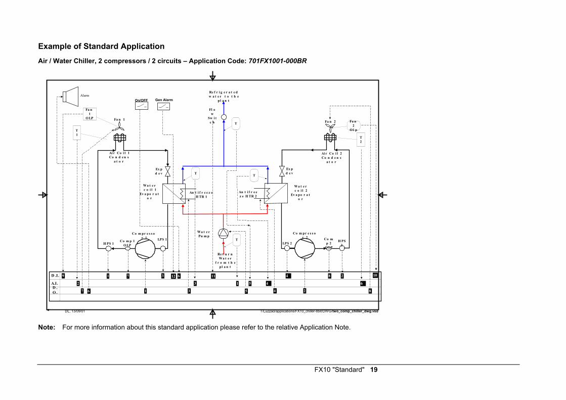
Example of Standard Application
Air / Water Chiller, 2 compressors / 2 circuits – Application Code: 701FX1001-000BR
Co m pr e s s or 1
Co m p 1O LPH PS 1
LPS 1
Ai r Co i l 1Co n d e n s
a t o r
Fa n 1
Co m pr e s s or 2 Co m
p 2O LP
LPS 2H PS
2
Ai r Co i l 2Co n d e n s
a t o r
Fa n 2
Wa t e rc o i l 1
Ev a po r a to r
Wa t e rc o i l 2
Ev a po r a to r
An t i f r e ez e H TR 2
An t i f r e e z eH TR 1
Fl ow
Sw i tc h
Ex pd e v
Ex pd e v
A.I.D .O .
D .I.
Fa n1
O LP
Re t u r nWa t e r
f r o m t h epl a n t
Re f r i g e r a t e dw a t e r t o t h e
pl a n t
Fa n2
O l p
Wa t e rPu m p
T
T T
T
T1
T2
2 10
T/Luzzad/applications/FX10_chiller-8bit/DWG/two_comp_chiller_dwg.vsdDL, 13/09/01
9 1 7 3 11 4 8
645132
1 3 5 4 2 87 6
Alarm
6
On/OFF Gen Alarm
12
Note: For more information about this standard application please refer to the relative Application Note.
20 FX10 "Standard"
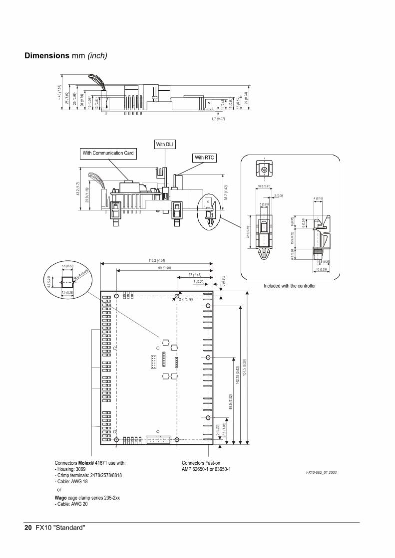
Dimensions mm (inch)
FX10-002_01 2003
~ 40
(1.5
7)
26 (1
.02)
25 (0
.98)
20 (0
.79)
15 (0
.59)
13 (0
.51)
1,7 (0.07)
13 (0
.51)
15 (0
.59)
25 (0
.98)
R 0.8 (0.03)
5.5 (0.22)
5.5 (0
.22)
7.1 (0.28)
10.5 (0.41)
2 (0.08)
5 (0.20)
22.5
(0.8
9)
10 (0.39)
6.5 (0.26)
6.5
(0.2
6)13
.5 (0
.53)
9 (0
.35)
6 (0
.24)
4 (0.16)
29.9
(1.1
8)
36.2
(1.4
2)
43.2
(1.7
)
5 (0.20)
5 (0.
20)
5 (0.
20)
37 (1.46)
99 (3.90)
Ø 4 (0.16)
157.5
(6.2
0)
115.2 (4.54)
27.5
(1.0
8)
89.5
(3.5
2)
142.7
5 (5.
62)
With Communication Card With DLI
Included with the controller
Connectors Molex® 41671 use with: - Housing: 3069 - Crimp terminals: 2478/2578/8818 - Cable: AWG 18 or Wago cage clamp series 235-2xx - Cable: AWG 20
Connectors Fast-on AMP 62650-1 or 63650-1
With RTC
FX10 "Standard" 21
Mounting Instructions1. Electrical panel mounting:
Prepare the holes on the electrical panel in order to fit the board holders. See "Dimensions" on page 20.
2. Insert the board holders within the appropriate holes in the PCB and snap the controller on the electrical panel. Make sure that all board holders snap in place.
3. Wiring terminations are made by detachable connectors, which accept 18 AWG cable in case the Molex® type is selected or 20 AWG, in case the cage clamp connection model is chosen.
4. Verify that the wiring has been correctly installed, and that voltage levels are appropriate for the various input signals according to the application.
! CAUTION
The CMOS circuits in the controller are sensitive to static electricity. Take suitable precautions.

22 FX10 "Standard"
General Wiring Guidelines While every reasonable precaution has been taken to prevent electrical disturbances from adversely affecting the operation of the controller, and the controller complies with appropriate local codes for electromagnetic compatibility (EMC), lack of attention to generally accepted control wiring installation practices can lead to controller problems in high electromagnetic field environments. In general, follow the guidelines below.
• Do not mount the controller in heavy-duty switch gear cabinets or in cabinets with frequency-converting or phase-cutting equipment.
• Low voltage wiring in electrical cabinets must be physically separated from line voltage and power wiring, and a distinctive colour (e.g. white or pink) is recommended.
• To avoid electrical interference in field cables: - Keep input and output point cable runs as short as possible (<50 m/165 feet ). - Use twisted pair cables. - Run low voltage cables separately from line voltage/power cables, and use a minimum of 30 cm / 12
inches separation for 230V, 30A circuits. - Do not run low voltage cables parallel to power cables for long distances (> 3m / 10 feet ). - Do not run cables close to transformers or high frequency generating equipment. - In high electromagnetic field environments, use shielded cable, grounding the drain wire at the controller
cabinet only. - Use a cable recommended for RS 485 transmission for the Supervisor Link and Local Link
(communications buses), and to the XT-Bus (extension module bus). If the cable is shielded, it must be grounded at one point only (normally at one end of the bus). (See the Technical Bulletin on the Metasys N2 Bus or System 91 Bus Converter and Repeater). If a two-wire cable is installed, the shield may be used for the RS 485 common (or reference) signal.
• Do not connect switched inductive loads to the 24 V transformer that supplies the controller. When multiple loads are connected to one transformer, cable each connected load from the transformer separately so that any possible disturbances from one load will have minimal affect on other loads.
The first diagram below shows the correct way to wire the controller to the transformer. The second diagram illustrates the incorrect way.
230 VAC 24 VAC ControllerOtherLoads
Fuses
dxv2cwtb
Correct Wiring of Controller to 24 V Transformer
! 230 VAC
dxv2iwtb
24 VAC
Fuse
OtherLoadsController
Incorrect Wiring of Controller to 24 V Transformer
Other Loads
Other Loads
NO!
FX10 "Standard" 23
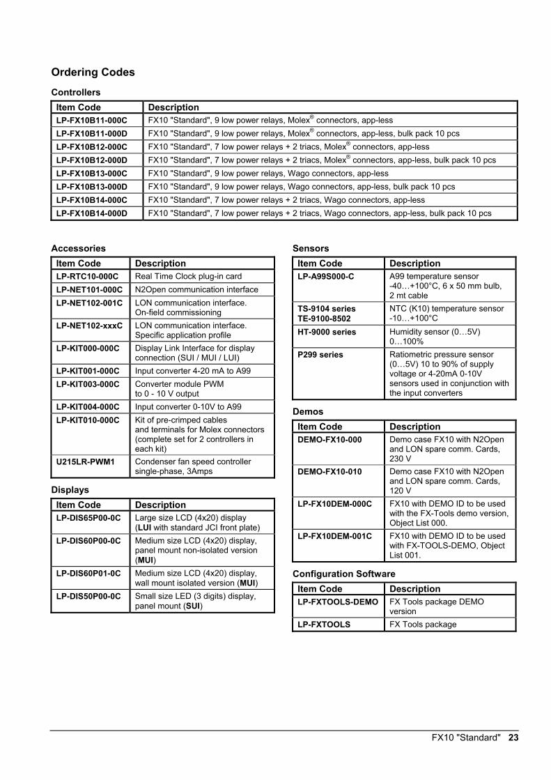
Ordering Codes
Controllers Item Code Description LP-FX10B11-000C FX10 "Standard", 9 low power relays, Molex® connectors, app-less LP-FX10B11-000D FX10 "Standard", 9 low power relays, Molex® connectors, app-less, bulk pack 10 pcs LP-FX10B12-000C FX10 "Standard", 7 low power relays + 2 triacs, Molex® connectors, app-less LP-FX10B12-000D FX10 "Standard", 7 low power relays + 2 triacs, Molex® connectors, app-less, bulk pack 10 pcs LP-FX10B13-000C FX10 "Standard", 9 low power relays, Wago connectors, app-less LP-FX10B13-000D FX10 "Standard", 9 low power relays, Wago connectors, app-less, bulk pack 10 pcs LP-FX10B14-000C FX10 "Standard", 7 low power relays + 2 triacs, Wago connectors, app-less LP-FX10B14-000D FX10 "Standard", 7 low power relays + 2 triacs, Wago connectors, app-less, bulk pack 10 pcs
Accessories Item Code Description LP-RTC10-000C Real Time Clock plug-in card LP-NET101-000C N2Open communication interface LP-NET102-001C LON communication interface.
On-field commissioning LP-NET102-xxxC LON communication interface.
Specific application profile LP-KIT000-000C Display Link Interface for display
connection (SUI / MUI / LUI) LP-KIT001-000C Input converter 4-20 mA to A99 LP-KIT003-000C Converter module PWM
to 0 - 10 V output LP-KIT004-000C Input converter 0-10V to A99 LP-KIT010-000C Kit of pre-crimped cables
and terminals for Molex connectors (complete set for 2 controllers in each kit)
U215LR-PWM1 Condenser fan speed controller single-phase, 3Amps
Displays Item Code Description LP-DIS65P00-0C Large size LCD (4x20) display
(LUI with standard JCI front plate) LP-DIS60P00-0C Medium size LCD (4x20) display,
panel mount non-isolated version (MUI)
LP-DIS60P01-0C Medium size LCD (4x20) display, wall mount isolated version (MUI)
LP-DIS50P00-0C Small size LED (3 digits) display, panel mount (SUI)
Sensors Item Code Description LP-A99S000-C A99 temperature sensor
-40…+100°C, 6 x 50 mm bulb, 2 mt cable
TS-9104 series TE-9100-8502
NTC (K10) temperature sensor -10…+100°C
HT-9000 series Humidity sensor (0…5V) 0…100%
P299 series Ratiometric pressure sensor (0…5V) 10 to 90% of supply voltage or 4-20mA 0-10V sensors used in conjunction with the input converters
Demos Item Code Description DEMO-FX10-000 Demo case FX10 with N2Open
and LON spare comm. Cards, 230 V
DEMO-FX10-010 Demo case FX10 with N2Open and LON spare comm. Cards, 120 V
LP-FX10DEM-000C FX10 with DEMO ID to be used with the FX-Tools demo version, Object List 000.
LP-FX10DEM-001C FX10 with DEMO ID to be used with FX-TOOLS-DEMO, Object List 001.
Configuration Software Item Code Description LP-FXTOOLS-DEMO FX Tools package DEMO
version LP-FXTOOLS FX Tools package
24 FX10 "Standard"
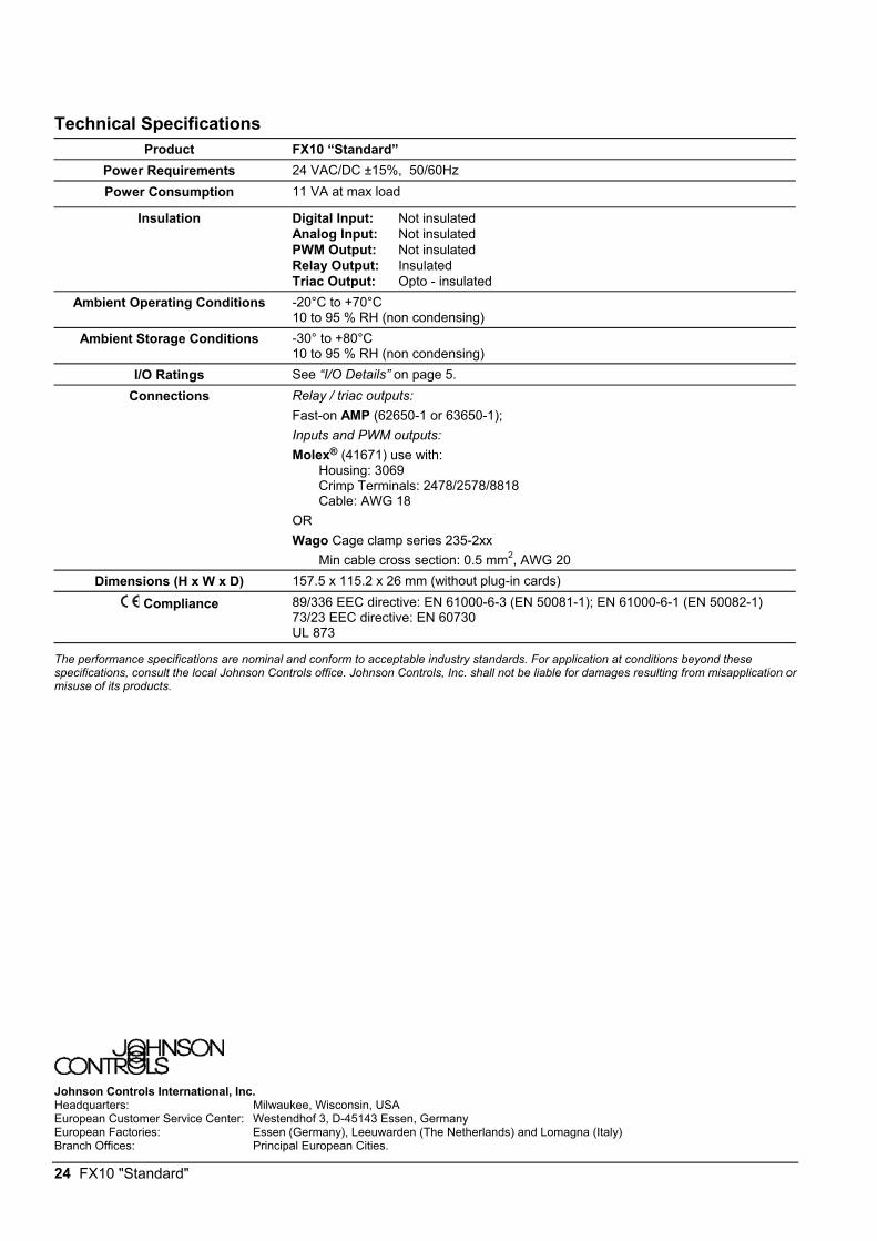
Technical Specifications Product FX10 “Standard”
Power Requirements 24 VAC/DC ±15%, 50/60Hz Power Consumption 11 VA at max load
Insulation Digital Input: Not insulated Analog Input: Not insulated PWM Output: Not insulated Relay Output: Insulated Triac Output: Opto - insulated
Ambient Operating Conditions -20°C to +70°C 10 to 95 % RH (non condensing)
Ambient Storage Conditions -30° to +80°C 10 to 95 % RH (non condensing)
I/O Ratings See “I/O Details” on page 5. Connections Relay / triac outputs:
Fast-on AMP (62650-1 or 63650-1); Inputs and PWM outputs: Molex® (41671) use with: Housing: 3069 Crimp Terminals: 2478/2578/8818 Cable: AWG 18 OR Wago Cage clamp series 235-2xx Min cable cross section: 0.5 mm2, AWG 20
Dimensions (H x W x D) 157.5 x 115.2 x 26 mm (without plug-in cards)
Compliance 89/336 EEC directive: EN 61000-6-3 (EN 50081-1); EN 61000-6-1 (EN 50082-1) 73/23 EEC directive: EN 60730 UL 873
The performance specifications are nominal and conform to acceptable industry standards. For application at conditions beyond these specifications, consult the local Johnson Controls office. Johnson Controls, Inc. shall not be liable for damages resulting from misapplication or misuse of its products.
Johnson Controls International, Inc. Headquarters: Milwaukee, Wisconsin, USA European Customer Service Center: Westendhof 3, D-45143 Essen, Germany European Factories: Essen (Germany), Leeuwarden (The Netherlands) and Lomagna (Italy) Branch Offices: Principal European Cities.
Top Related